AS-i 3.0 Safety Monitor for 2 AS-i circuits - EUCHNER GmbH + Co. KG
AS-i 3.0 Safety Monitor for 2 AS-i circuits - EUCHNER GmbH + Co. KG
AS-i 3.0 Safety Monitor for 2 AS-i circuits - EUCHNER GmbH + Co. KG

You also want an ePaper? Increase the reach of your titles
YUMPU automatically turns print PDFs into web optimized ePapers that Google loves.
<strong>AS</strong>-i <strong>Safety</strong> <strong>Monitor</strong> <strong>for</strong> 2 <strong>AS</strong>-i <strong>circuits</strong><br />
User Manual<br />
Revision date: 2008-10-24
Subject to modifications without notice.<br />
Generally, this manual refers to products<br />
without mentioning existing patents,<br />
utility models, or trademarks.<br />
The absence of any such references does<br />
not indicate that a product is patent-free.<br />
© Euchner <strong>GmbH</strong> + <strong>Co</strong>. <strong>KG</strong><br />
Kohlhammerstr. 16<br />
D-70771 Leinfelden-Echterdingen
<strong>AS</strong>-i <strong>Safety</strong> <strong>Monitor</strong> <strong>for</strong> 2 <strong>AS</strong>-i <strong>circuits</strong><br />
Table of contents<br />
Table of contents<br />
<strong>AS</strong>-i <strong>Safety</strong> <strong>Monitor</strong> <strong>for</strong> 2 <strong>AS</strong>-i <strong>circuits</strong><br />
1 Symbol catalog .....................................................................................9<br />
1.1 Abbreviations ................................................................................................... 9<br />
2 General ................................................................................................10<br />
2.1 Product in<strong>for</strong>mation....................................................................................... 10<br />
2.2 Brief description ............................................................................................ 11<br />
2.3 <strong>Co</strong>n<strong>for</strong>mity statement.................................................................................... 12<br />
2.4 Certification according to DIN EN ISO 9001 : 2000..................................... 12<br />
3 <strong>Safety</strong>...................................................................................................13<br />
3.1 <strong>Safety</strong> standard .............................................................................................. 13<br />
3.2 Intended use................................................................................................... 13<br />
3.2.1 <strong>Co</strong>nditions of use..........................................................................................................13<br />
3.2.2 Residual risks (EN 292-1) ............................................................................................. 13<br />
3.2.3 Areas of application...................................................................................................... 13<br />
3.3 Organizational requirements ........................................................................ 14<br />
3.3.1 Documentation ..............................................................................................................14<br />
3.3.2 Traceability of the devices ........................................................................................... 14<br />
3.3.3 <strong>Safety</strong> regulations .........................................................................................................14<br />
3.3.4 Qualified personnel....................................................................................................... 15<br />
3.3.5 Repair............................................................................................................................. 15<br />
3.4 Disposal .......................................................................................................... 15<br />
4 Spezifications .....................................................................................16<br />
4.1 Technical data ................................................................................................ 16<br />
4.1.1 Data sheet 103303 ......................................................................................................... 16<br />
4.2 <strong>Co</strong>nsideration of failure probability according to IEC 61 508.................... 18<br />
4.3 Scope of delivery ........................................................................................... 18<br />
5 Installation...........................................................................................19<br />
5.1 Dimensions..................................................................................................... 19<br />
5.2 <strong>Co</strong>nnections ................................................................................................... 19<br />
5.3 Installing in the control cabinet.................................................................... 20<br />
5.4 Removing........................................................................................................ 20<br />
5.5 Electrical <strong>Co</strong>nnection .................................................................................... 21<br />
Subject to reasonable modifications due to technical advances Id.-No.: 103336 Issue date - 24.10.2008 <strong>EUCHNER</strong> <strong>GmbH</strong> + <strong>Co</strong>. <strong>KG</strong><br />
3<br />
Kohlhammerstraße 16 • D-70771 Leinfelden-Echterdingen Tel. +49/711/75 97-0 • Fax. +49/711/753316
<strong>AS</strong>-i <strong>Safety</strong> <strong>Monitor</strong> <strong>for</strong> 2 <strong>AS</strong>-i <strong>circuits</strong><br />
Table of contents<br />
5.6 <strong>Co</strong>mmissioning ..............................................................................................21<br />
5.6.1 Supply voltage <strong>for</strong> <strong>AS</strong>-I <strong>Safety</strong> <strong>Monitor</strong> .......................................................................21<br />
5.6.2 Duplicate address recognition .....................................................................................21<br />
5.6.2.1 <strong>AS</strong>-i Master without duplicate address recognition.......................................................21<br />
5.6.2.2 <strong>AS</strong>-i Master with duplicate address recognition............................................................22<br />
5.6.3 Replacing the chip card ................................................................................................23<br />
5.6.4 Local parameter setting of safe <strong>AS</strong>-i/Gateways and <strong>Monitor</strong>s..................................24<br />
5.6.5 Replacing a defective safety-configured <strong>AS</strong>-i slave ..................................................26<br />
5.7 Safe configuration using <strong>AS</strong>IMON 3 G2 .......................................................27<br />
6 Maintenance ....................................................................................... 29<br />
6.1 Checking <strong>for</strong> safe turn-off .............................................................................29<br />
7 Electrical connection ......................................................................... 30<br />
7.1 Overview of terminals, indicators and operating elements .......................30<br />
7.1.1 103303.............................................................................................................................30<br />
7.2 <strong>AS</strong>-i bus connection.......................................................................................31<br />
7.3 In<strong>for</strong>mation about the device types..............................................................31<br />
7.4 <strong>AS</strong>-i and power supply terminal assignments.............................................31<br />
7.4.1 Electrical connection 103303 ......................................................................................32<br />
7.5 Diagnostics interface .....................................................................................33<br />
7.5.1 103303.............................................................................................................................33<br />
7.6 Chip card.........................................................................................................33<br />
7.7 Release <strong>circuits</strong> ..............................................................................................34<br />
7.7.1 Wiring overview of <strong>Safety</strong> <strong>Monitor</strong> 103303..................................................................34<br />
7.8 Indicators and operating elements...............................................................35<br />
7.8.1 LED indicators – <strong>Monitor</strong> 103303 ................................................................................35<br />
7.8.2 LED indicators safety unit in 103303 ...........................................................................36<br />
7.8.3 Buttons ...........................................................................................................................37<br />
8 Function and startup of the <strong>Safety</strong> <strong>Monitor</strong>..................................... 38<br />
8.1 Powering up the device .................................................................................38<br />
8.2 <strong>Co</strong>nfiguration of the safety functions ..........................................................38<br />
8.2.1 Description of configuration using <strong>AS</strong>IMON 3 G2 software......................................39<br />
8.2.2 Description of configuration using chip card with master configuration................40<br />
8.2.3 <strong>Co</strong>nfiguration using a chip card with complete configuration..................................40<br />
8.3 <strong>Safety</strong>-relevant documentation of the application ......................................41<br />
8.4 Diagnostic data...............................................................................................41<br />
8.4.1 Switch-off history ..........................................................................................................42<br />
8.4.2 Profile and diagnostics using <strong>AS</strong>-i ..............................................................................42<br />
8.5 Password protection......................................................................................42<br />
8.5.1 Procedure <strong>for</strong> configuring and teaching code sequences ........................................42<br />
8.5.2 Function of the ESC/Service key .................................................................................43<br />
8.6 Safe coupling slaves on the <strong>AS</strong>-i <strong>circuits</strong> ....................................................44<br />
8.7 Chip card.........................................................................................................44<br />
4<br />
Subject to reasonable modifications due to technical advances Id.-No.: 103336 Issue date - 24.10.2008 <strong>EUCHNER</strong> <strong>GmbH</strong> + <strong>Co</strong>. <strong>KG</strong><br />
Kohlhammerstraße 16 • D-70771 Leinfelden-Echterdingen Tel. +49/711/75 97-0 • Fax. +49/711/753316
<strong>AS</strong>-i <strong>Safety</strong> <strong>Monitor</strong> <strong>for</strong> 2 <strong>AS</strong>-i <strong>circuits</strong><br />
Table of contents<br />
8.7.1 Unsafe data.................................................................................................................... 44<br />
8.7.1.1 Card un<strong>for</strong>matted .........................................................................................................44<br />
8.7.1.2 Data not compatible ..................................................................................................... 45<br />
8.7.1.3 Card empty................................................................................................................... 45<br />
8.7.1.4 ..................................................................................................................................... 45<br />
8.7.1.5 Data compatible ........................................................................................................... 45<br />
8.7.1.6 Data in the device and on the chip card identical......................................................... 45<br />
8.7.1.7 Data in the device and on the chip card not identical................................................... 46<br />
8.7.1.8 Safe data...................................................................................................................... 46<br />
8.7.1.9 Data incompatible ........................................................................................................46<br />
8.7.1.10 Data compatible ........................................................................................................... 46<br />
8.7.1.11 <strong>Co</strong>mplete configuration ................................................................................................ 47<br />
8.7.1.12 Data on the chip card and in the device are identical .................................................. 47<br />
8.7.1.13 Data not identical ......................................................................................................... 47<br />
8.7.1.14 Operating the chip card from the menu........................................................................ 48<br />
8.7.2 Working with multiple memory banks ........................................................................ 48<br />
9 Operation in advanced display mode...............................................50<br />
9.1 Overview ......................................................................................................... 50<br />
9.2 Navigation in advanced mode ...................................................................... 52<br />
9.3 <strong>AS</strong>-I SAFETY................................................................................................... 53<br />
9.3.1 TEACH CODES .............................................................................................................. 53<br />
9.3.1.1 TEACH CODES – COMPLETE ................................................................................... 53<br />
9.3.1.2 SINGLE SLAVE ........................................................................................................... 55<br />
9.3.1.3 COUPLING SLAVE...................................................................................................... 56<br />
9.3.1.4 INPUT CODE SEQ. ..................................................................................................... 57<br />
9.3.2 SAFE OUTPUT CH (channels <strong>for</strong> the release <strong>circuits</strong>) .............................................. 58<br />
9.3.3 SAFE COUPLING (optional menu)............................................................................... 58<br />
9.3.4 START/STOP (changing the <strong>Monitor</strong> mode)............................................................... 58<br />
9.3.5 CLEAR SAFE CFG (delete safe configuration)........................................................... 59<br />
9.3.6 PIN (changing the PIN) ................................................................................................. 59<br />
9.3.7 SAFE CHIPCARD........................................................................................................... 60<br />
9.3.7.1 VIEW BANK X CONFIG (view active bank) ................................................................. 60<br />
9.3.7.2 CARD –>MONITOR (copy card data to the <strong>Monitor</strong>) ................................................... 61<br />
9.3.7.3 MONITOR –>CARD (copy <strong>Monitor</strong> data to the chip card) ........................................... 63<br />
9.3.7.4 CLEAR CODES (delete code sequences) ................................................................... 64<br />
9.3.7.5 CLEAR SAFE CARD.................................................................................................... 65<br />
9.3.8 PROTECT (protect safe configuration) ....................................................................... 66<br />
9.4 DIAGNOSTICS ................................................................................................ 66<br />
9.4.1 <strong>AS</strong>-I CIRCUIT (Selecting the <strong>AS</strong>-i circuit).................................................................... 67<br />
9.4.2 SAFETY SLAVES (safety oriented slaves).................................................................. 67<br />
9.4.3 MONITOR ....................................................................................................................... 67<br />
9.4.3.1 DIAGNOSIS ................................................................................................................. 69<br />
9.4.3.2 L<strong>AS</strong>T DIAGNOSIS ....................................................................................................... 70<br />
9.4.3.3 MONITOR CONFIG ..................................................................................................... 72<br />
9.4.4 FAULT DETECTOR........................................................................................................ 72<br />
9.4.5 ERROR COUNTERS ...................................................................................................... 74<br />
9.4.6 LPF (List of Peripheral Faults) ..................................................................................... 74<br />
9.4.7 <strong>AS</strong>-I MONITOR (Info) ..................................................................................................... 75<br />
9.5 SETUP ............................................................................................................. 76<br />
9.5.1 CHIPCARD ..................................................................................................................... 76<br />
9.5.2 Language (menu language) ......................................................................................... 77<br />
9.5.3 FACTORY RESET (factory default settings)............................................................... 77<br />
9.6 DISPLAY CONTR<strong>AS</strong>T (set display contrast) ............................................... 78<br />
Subject to reasonable modifications due to technical advances Id.-No.: 103336 Issue date - 24.10.2008 <strong>EUCHNER</strong> <strong>GmbH</strong> + <strong>Co</strong>. <strong>KG</strong><br />
5<br />
Kohlhammerstraße 16 • D-70771 Leinfelden-Echterdingen Tel. +49/711/75 97-0 • Fax. +49/711/753316
<strong>AS</strong>-i <strong>Safety</strong> <strong>Monitor</strong> <strong>for</strong> 2 <strong>AS</strong>-i <strong>circuits</strong><br />
Table of contents<br />
10 <strong>Co</strong>nfiguration mit Windows Software <strong>AS</strong>IMON 3 G2 ...................... 79<br />
11 Diagnostics <strong>for</strong> <strong>AS</strong>-i <strong>Monitor</strong> and networking using <strong>AS</strong>-i Master.. 80<br />
11.1 Introduction ....................................................................................................80<br />
11.2 On-location operation ....................................................................................80<br />
11.3 Spontaneous messages ................................................................................80<br />
11.4 Diagnostics using Profile S-7.5.5..................................................................81<br />
11.4.1 Binary data .....................................................................................................................81<br />
11.4.2 Transparent input data..................................................................................................81<br />
11.4.2.1 Status codes <strong>for</strong> the release <strong>circuits</strong> (OSSD) ...............................................................83<br />
11.4.2.2 Transparent output data ...............................................................................................83<br />
11.4.3 Acyclical data.................................................................................................................83<br />
11.4.3.1 Vendor Specific Object 2 - Analyzer status <strong>AS</strong>-i Circuit 2 ............................................84<br />
11.4.3.2 Vendor Specific Object 7 – Device <strong>Co</strong>lors OSSD 1......................................................84<br />
11.4.3.3 Vendor Specific Object 8 - Device <strong>Co</strong>lors OSSD 1 with component index association 86<br />
11.4.3.4 Vendor Specific Object 9 - Device <strong>Co</strong>lors at switch off OSSD 1 ..................................87<br />
11.4.3.5 Vendor Specific Object 10 - Device <strong>Co</strong>lors OSSD 1 with component<br />
index association.........................................................................................................89<br />
11.4.3.6 Vendor-Specific Object 11 ... 70 ...................................................................................90<br />
12 Status indication, faults and fault elimination................................. 92<br />
12.1 Spontaneous display of faults from the safety unit....................................92<br />
12.2 Replacing a defective safety-configured <strong>AS</strong>-i slave ...................................93<br />
12.3 Replacing a defective <strong>AS</strong>-i <strong>Safety</strong> <strong>Monitor</strong> ..................................................94<br />
12.4 Forget the password? What do I do now?...................................................94<br />
13 Glossary: As-i terms .......................................................................... 96<br />
14 Accessories ........................................................................................ 99<br />
14.1 <strong>AS</strong>-i <strong>Safety</strong> at Work ........................................................................................99<br />
14.1.1 <strong>AS</strong>-i <strong>3.0</strong> PROFIBUS-Gateway with integrated <strong>Safety</strong> <strong>Monitor</strong> Features: ..................99<br />
15 Reference List .................................................................................. 100<br />
15.1 Manual: “<strong>AS</strong>IMON 3 G2 <strong>Co</strong>nfiguration Software“ .....................................100<br />
15.2 Sources .........................................................................................................100<br />
16 Your opinion is important to us!..................................................... 101<br />
6<br />
Subject to reasonable modifications due to technical advances Id.-No.: 103336 Issue date - 24.10.2008 <strong>EUCHNER</strong> <strong>GmbH</strong> + <strong>Co</strong>. <strong>KG</strong><br />
Kohlhammerstraße 16 • D-70771 Leinfelden-Echterdingen Tel. +49/711/75 97-0 • Fax. +49/711/753316
<strong>AS</strong>-i <strong>Safety</strong> <strong>Monitor</strong> <strong>for</strong> 2 <strong>AS</strong>-i <strong>circuits</strong><br />
Declaration of <strong>Co</strong>n<strong>for</strong>mity<br />
Declaration of <strong>Co</strong>n<strong>for</strong>mity<br />
Subject to reasonable modifications due to technical advances Id.-No.: 103336 Issue date - 24.10.2008 <strong>EUCHNER</strong> <strong>GmbH</strong> + <strong>Co</strong>. <strong>KG</strong><br />
7<br />
Kohlhammerstraße 16 • D-70771 Leinfelden-Echterdingen Tel. +49/711/75 97-0 • Fax. +49/711/753316
<strong>AS</strong>-i <strong>Safety</strong> <strong>Monitor</strong> <strong>for</strong> 2 <strong>AS</strong>-i <strong>circuits</strong><br />
8<br />
Subject to reasonable modifications due to technical advances Id.-No.: 103336 Issue date - 24.10.2008 <strong>EUCHNER</strong> <strong>GmbH</strong> + <strong>Co</strong>. <strong>KG</strong><br />
Kohlhammerstraße 16 • D-70771 Leinfelden-Echterdingen Tel. +49/711/75 97-0 • Fax. +49/711/753316
<strong>AS</strong>-i <strong>Safety</strong> <strong>Monitor</strong> <strong>for</strong> 2 <strong>AS</strong>-i <strong>circuits</strong><br />
Symbol catalog<br />
1. Symbol catalog<br />
In<strong>for</strong>mation!<br />
This symbol indicates important in<strong>for</strong>mation.<br />
Attention!<br />
This symbol warns of a potential failure. Non-compliance may lead to interruptions of<br />
the device, the connected peripheral systems, or plant, potentially leading to total malfunctioning.<br />
Warning!<br />
This symbol warns of an imminent danger. Non-compliance may lead to personal injuries<br />
that could be fatal or result in material damages and destruction.<br />
1.1 Abbreviations<br />
<strong>AS</strong>-i<br />
AOPD<br />
CRC<br />
I/O<br />
EDM<br />
EMC<br />
ESD<br />
PELV<br />
PFD<br />
PLC<br />
<strong>AS</strong>-interface (actuator sensor interface)<br />
Active opto-electronic protective device<br />
Cyclic redundancy check<br />
Input/output<br />
External device monitoring<br />
Electromagnetic compliance<br />
Electrostatic discharge<br />
Protective extra-low voltage<br />
Probability of failure on demand<br />
Programmable logic control<br />
In<strong>for</strong>mation!<br />
Additional in<strong>for</strong>mation can be found in section .<br />
Subject to reasonable modifications due to technical advances Id.-No.: 103336 Issue date - 24.10.2008 <strong>EUCHNER</strong> <strong>GmbH</strong> + <strong>Co</strong>. <strong>KG</strong><br />
9<br />
Kohlhammerstraße 16 • D-70771 Leinfelden-Echterdingen Tel. +49/711/75 97-0 • Fax. +49/711/753316
<strong>AS</strong>-i <strong>Safety</strong> <strong>Monitor</strong> <strong>for</strong> 2 <strong>AS</strong>-i <strong>circuits</strong><br />
General<br />
2. General<br />
2.1 Product in<strong>for</strong>mation<br />
This system manual applies to the following Euchner <strong>GmbH</strong> + <strong>Co</strong>. <strong>KG</strong> equipment:<br />
<strong>AS</strong>-i <strong>Safety</strong> <strong>Monitor</strong> <strong>for</strong> 2 <strong>AS</strong>-i <strong>circuits</strong><br />
RS 232 diagnostic port<br />
103303<br />
Tab. 2-1.<br />
The <strong>AS</strong>-i <strong>Safety</strong> <strong>Monitor</strong> in a stainless steel enclosure is an E-STOP switching device<br />
which monitors safety configured slaves and correct function of the network.<br />
The safety unit provides 4 inputs which can be defined as either EDM or as<br />
START inputs.<br />
The unit features two hierarchically equal <strong>AS</strong>-i <strong>circuits</strong> and four output switching<br />
elements (two safety relays and two semiconductor outputs).<br />
Features:<br />
• Greater computing power to allow more function modules<br />
• Graphical display <strong>for</strong> better diagnostics<br />
• Optional storing of configuration data on an interchangeable memory card.<br />
• EDM & START inputs can be defined freely<br />
Functions of the device<br />
Device<br />
OSSDs<br />
<strong>AS</strong>-i<br />
Diagnostics<br />
interface<br />
Semiconductor<br />
outputs<br />
SaW outputs<br />
<strong>Safety</strong> relays<br />
<strong>Safety</strong> devices<br />
103303 16 2 RS 232 2 16 2 256<br />
Caption<br />
Tab. 2-2.<br />
OSSDs: number of release <strong>circuits</strong><br />
16: safety unit generates 16 independent switching signals<br />
<strong>AS</strong>-i: number of <strong>AS</strong>-i <strong>circuits</strong><br />
2: safety unit functions with two equal <strong>AS</strong>-i <strong>circuits</strong><br />
Diagnostics interface: type of diagnostic port<br />
Semiconductor number of semiconductor outputs:<br />
outputs:<br />
SaW outputs: number of SaW outputs<br />
<strong>Safety</strong> relays: number of safety relays<br />
<strong>Safety</strong> devices: number of safety devices<br />
Tab. 2-3.<br />
10<br />
Subject to reasonable modifications due to technical advances Id.-No.: 103336 Issue date - 24.10.2008 <strong>EUCHNER</strong> <strong>GmbH</strong> + <strong>Co</strong>. <strong>KG</strong><br />
Kohlhammerstraße 16 • D-70771 Leinfelden-Echterdingen Tel. +49/711/75 97-0 • Fax. +49/711/753316
<strong>AS</strong>-i <strong>Safety</strong> <strong>Monitor</strong> <strong>for</strong> 2 <strong>AS</strong>-i <strong>circuits</strong><br />
General<br />
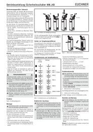
2.2 Brief description<br />
The Actuator-Sensor-Interface (<strong>AS</strong>-i) has been established as a system <strong>for</strong> networking<br />
primarily binary sensors and actuators on the lowest level of the automation<br />
hierarchy. The large number of installed systems, ease of use and reliable<br />
operating behavior make <strong>AS</strong>-i also ideal <strong>for</strong> machine safety applications.<br />
The safe <strong>AS</strong>-i system is intended <strong>for</strong> safety applications up to Category 4/SIL 3.<br />
Mixed use of standard components and safety components is possible.<br />
The <strong>AS</strong>-i <strong>Safety</strong> <strong>Monitor</strong> per<strong>for</strong>ms monitoring within an <strong>AS</strong>-i system of the userassigned<br />
safety slaves based on the configuration the user has set using configuration<br />
software. In case of a Stop request or a fault condition, the <strong>AS</strong>-i <strong>Safety</strong><br />
<strong>Monitor</strong> safety shuts off the system with a response time of maximum 40 ms.<br />
<strong>AS</strong>-i Gateway<br />
Standard<br />
module<br />
<strong>AS</strong>-i <strong>Safety</strong> monitor<br />
<strong>Safety</strong><br />
E-STOP switch<br />
<strong>Safety</strong><br />
module<br />
<strong>AS</strong>-i power supply<br />
<strong>Safety</strong><br />
light grid<br />
<strong>Safety</strong><br />
limit switch<br />
<strong>Safety</strong> light grid<br />
Standard-<br />
Modul<br />
Abb. 2-1.<br />
<strong>Safety</strong> configured and standard components in an <strong>AS</strong>-i network<br />
Multiple <strong>Safety</strong> <strong>Monitor</strong>s can be used within one <strong>AS</strong>-i system. A safe slave can be<br />
monitored by more than one <strong>AS</strong>-i <strong>Safety</strong> <strong>Monitor</strong>.<br />
Subject to reasonable modifications due to technical advances Id.-No.: 103336 Issue date - 24.10.2008 <strong>EUCHNER</strong> <strong>GmbH</strong> + <strong>Co</strong>. <strong>KG</strong><br />
11<br />
Kohlhammerstraße 16 • D-70771 Leinfelden-Echterdingen Tel. +49/711/75 97-0 • Fax. +49/711/753316
<strong>AS</strong>-i <strong>Safety</strong> <strong>Monitor</strong> <strong>for</strong> 2 <strong>AS</strong>-i <strong>circuits</strong><br />
General<br />
2.3 <strong>Co</strong>n<strong>for</strong>mity statement<br />
The <strong>AS</strong>-i <strong>Safety</strong> <strong>Monitor</strong> <strong>for</strong> 2 <strong>AS</strong>-i <strong>circuits</strong> has been developed and manufactured<br />
in accordance with the applicable european standards and directives.<br />
In<strong>for</strong>mation!<br />
The corresponding con<strong>for</strong>mity statement can be found at the very beginning of<br />
this system manual.<br />
2.4 Certification according to DIN EN ISO 9001 : 2000<br />
The manufacturer of the product possesses a certified quality assurance system<br />
in accordance with ISO 9001.<br />
In<strong>for</strong>mation!<br />
The current certificate can be viewed in internet: http://www.euchner.de<br />
12<br />
Subject to reasonable modifications due to technical advances Id.-No.: 103336 Issue date - 24.10.2008 <strong>EUCHNER</strong> <strong>GmbH</strong> + <strong>Co</strong>. <strong>KG</strong><br />
Kohlhammerstraße 16 • D-70771 Leinfelden-Echterdingen Tel. +49/711/75 97-0 • Fax. +49/711/753316
<strong>AS</strong>-i <strong>Safety</strong> <strong>Monitor</strong> <strong>for</strong> 2 <strong>AS</strong>-i <strong>circuits</strong><br />
<strong>Safety</strong><br />
3. <strong>Safety</strong><br />
3.1 <strong>Safety</strong> standard<br />
The <strong>AS</strong>-I <strong>Safety</strong> <strong>Monitor</strong> has been developed, manufactured, tested and submitted<br />
<strong>for</strong> type testing in accordance with the safety standards prevailing at the time<br />
of testing. The safety requirements per Category 4 in accordance with EN 954-1<br />
and Per<strong>for</strong>mance Level “e” in accordance with EN ISO 13 849-1 are met by all<br />
devices.<br />
In<strong>for</strong>mation!<br />
A detailed listing of the values <strong>for</strong> probability of failure (PFD values) can be found in<br />
section .<br />
Following a risk analysis you can sue the <strong>AS</strong>-I <strong>Safety</strong> <strong>Monitor</strong> in accordance with<br />
its safety category as a shut-down protection device <strong>for</strong> protecting hazardous areas.<br />
3.2 Intended use<br />
3.2.1 <strong>Co</strong>nditions of use<br />
The <strong>AS</strong>-I <strong>Safety</strong> <strong>Monitor</strong> has been developed as a shut-down protection device<br />
<strong>for</strong> protecting hazardous areas on powered equipment.<br />
Attention!<br />
Protection of operating personnel and equipment is not provided is the device is<br />
not used in accordance with its intended use.<br />
Attention!<br />
Manipulation of and changes to the devices other than expressly described in this<br />
Manual are not permitted.<br />
3.2.2 Residual risks (EN 292-1)<br />
The <strong>circuits</strong> suggested in this Manual have been tested and verified with the<br />
greatest care. The prevailing standards and regulations are met when using the<br />
components and wiring shown. Residual risks remain if:<br />
• There are any deviations from the suggested wiring concept which may result<br />
in the connected safety-relevant assemblies or protective devices not being<br />
incorporated or only insufficiently incorporated into the safety circuit.<br />
• The operator does not follow the prevailing safety regulations <strong>for</strong> operation,<br />
setting and maintenance of the machine. Machine inspection and maintenance<br />
intervals must be strictly observed.<br />
3.2.3 Areas of application<br />
The <strong>AS</strong>-I <strong>Safety</strong> <strong>Monitor</strong>, when properly used, enables the operation of sensorcontrolled<br />
personal protection equipment and additional safety components.<br />
Subject to reasonable modifications due to technical advances Id.-No.: 103336 Issue date - 24.10.2008 <strong>EUCHNER</strong> <strong>GmbH</strong> + <strong>Co</strong>. <strong>KG</strong><br />
13<br />
Kohlhammerstraße 16 • D-70771 Leinfelden-Echterdingen Tel. +49/711/75 97-0 • Fax. +49/711/753316
<strong>AS</strong>-i <strong>Safety</strong> <strong>Monitor</strong> <strong>for</strong> 2 <strong>AS</strong>-i <strong>circuits</strong><br />
<strong>Safety</strong><br />
The device also assumes the mandatory E-STOP function (Stop Category 0 or 1)<br />
<strong>for</strong> all non-manually operated machines, dynamic monitoring of the restart function<br />
and the protection monitoring function.<br />
Examples <strong>for</strong> use of the <strong>AS</strong>-I <strong>Safety</strong> <strong>Monitor</strong>:<br />
The device is used economically in machines and equipment in which the standard<br />
<strong>AS</strong>-I bus is the local bus. Using the <strong>Safety</strong> <strong>Monitor</strong> as a bus component allows<br />
already existing <strong>AS</strong>-I bus configurations to be easily expanded, and safety<br />
components having the corresponding <strong>AS</strong>-i <strong>Safety</strong> at Work interface can be inserted<br />
without difficulty. If there is no <strong>AS</strong>-I <strong>Safety</strong> at Work interface on the safety<br />
component, so-called coupling modules can be used to establish the connection.<br />
Existing <strong>AS</strong>-I masters and <strong>AS</strong>-I power supplies can be used as well.<br />
There are no industry-specific restrictions. Some of the key applications are listed<br />
below:<br />
• Machine tools<br />
• Expanded machining centers with multiple control elements and safety sensors<br />
<strong>for</strong> wood and metal processing<br />
• Printing and paper processing machines, trimming machines<br />
• Packaging machinery, both stand-alone and as systems<br />
• Food and beverage machinery<br />
• Workpiece and bulk material conveying systems<br />
• Rubber and plastics industry processing machinery<br />
• Automatic assembly and handling equipment<br />
3.3 Organizational requirements<br />
3.3.1 Documentation<br />
All the specifications in this System Manual, in particular the sections “<strong>Safety</strong> Instructions”<br />
and “<strong>Co</strong>mmissioning”, must be strictly observed.<br />
All the safety instructions in the manual “<strong>AS</strong>IMON 3 G2 <strong>Co</strong>nfiguration Software”<br />
must be strictly observed.<br />
Please note the safety rules when configuring the safety functions, see section<br />
. Checking of the release code and testing<br />
the system must be documented in writing and is part of the system documentation.<br />
Keep this System Manual in a safe location where it can be readily accessed. It<br />
should always be available.<br />
3.3.2 Traceability of the devices<br />
The ordering party is responsible <strong>for</strong> ensuring traceability of the devices by serial<br />
number!<br />
3.3.3 <strong>Safety</strong> regulations<br />
Observe the locally prevailing legal regulations and requirements of the trade associations.<br />
14<br />
Subject to reasonable modifications due to technical advances Id.-No.: 103336 Issue date - 24.10.2008 <strong>EUCHNER</strong> <strong>GmbH</strong> + <strong>Co</strong>. <strong>KG</strong><br />
Kohlhammerstraße 16 • D-70771 Leinfelden-Echterdingen Tel. +49/711/75 97-0 • Fax. +49/711/753316
<strong>AS</strong>-i <strong>Safety</strong> <strong>Monitor</strong> <strong>for</strong> 2 <strong>AS</strong>-i <strong>circuits</strong><br />
<strong>Safety</strong><br />
3.3.4 Qualified personnel<br />
Installation, commissioning and maintenance of the devices are to be per<strong>for</strong>med<br />
only by qualified specialists.<br />
Electrical work is to be per<strong>for</strong>med only by electrical technicians.<br />
Setting and changing the device configuration via PC and <strong>AS</strong>IMON 3 G2 configuration<br />
software are to be per<strong>for</strong>med only by an authorized safety representative.<br />
The password <strong>for</strong> changing a device configuration must be kept under lock and<br />
key by the safety representative.<br />
3.3.5 Repair<br />
Repairs, in particular opening of the housing, are to be per<strong>for</strong>med only by the<br />
manufacturer or by an authorized representative of the manufacturer.<br />
3.4 Disposal<br />
In<strong>for</strong>mation!<br />
Electronic waste is hazardous waste. Please comply with all local ordinances when<br />
disposing this product!<br />
The device does not contain batteries that need to be removed be<strong>for</strong>e disposing it.<br />
Subject to reasonable modifications due to technical advances Id.-No.: 103336 Issue date - 24.10.2008 <strong>EUCHNER</strong> <strong>GmbH</strong> + <strong>Co</strong>. <strong>KG</strong><br />
15<br />
Kohlhammerstraße 16 • D-70771 Leinfelden-Echterdingen Tel. +49/711/75 97-0 • Fax. +49/711/753316
<strong>AS</strong>-i <strong>Safety</strong> <strong>Monitor</strong> <strong>for</strong> 2 <strong>AS</strong>-i <strong>circuits</strong><br />
Spezifications<br />
4. Spezifications<br />
4.1 Technical data<br />
Attention!<br />
The <strong>AS</strong>-I power supply <strong>for</strong> the <strong>AS</strong>-I components must have isolation per IEC 60<br />
742 and be able to handle momentary power interruptions of up to 20 ms. The<br />
power supply <strong>for</strong> the 24 V supply must also have isolation per IEC 60 742 and be<br />
able to handle momentary power interruptions of up to 20 ms. The maximum output<br />
voltage of the power supply must also be less than 42 V in case of a fault.<br />
4.1.1 Data sheet 103303<br />
103303<br />
<strong>Safety</strong> monitor<br />
Release circuit<br />
Start delay<br />
Respond delay<br />
Baud rate<br />
Inputs:<br />
4 x EDM/Start<br />
Outputs:<br />
4 x output switching elements<br />
Interface<br />
Displays<br />
LCD<br />
LED power<br />
LED fault<br />
advanced monitor<br />
4-channel<br />
< 10 s<br />
< 40 ms<br />
19,2 kBaud, no parity, 1 start bit, 1 stop bit, 8 data bits<br />
EDM: inputs of external device monitoring <strong>circuits</strong><br />
Start: start inputs<br />
switching current statical 4 mA at 24 V, dynamic 30 mA at 24 V (T=100 µs)<br />
relay outputs (output <strong>circuits</strong> 1 and 2)<br />
max. contact load: 3 A AC-15 at 30 V, 3 A DC-13 at 30 V<br />
semiconductor outputs (output <strong>circuits</strong> 3 and 4)<br />
max. contact load: 0,5 A DC-13 at 30 V<br />
RS 232, chip card slot<br />
indication of slave addresses and error messages<br />
<strong>AS</strong>-i voltage OK<br />
LED on: communication error on <strong>AS</strong>-i network<br />
LED flashing: at least 1 OSSD in state „red flashing“<br />
LED ready<br />
LED on: start-up/restart-disable active<br />
LED flashing: external test necessary<br />
LEDs U <strong>AS</strong>-i 1 / U <strong>AS</strong>-i 2<br />
<strong>AS</strong>-i 1/<strong>AS</strong>-i 2 sufficiently voltage supplied<br />
LED AUX<br />
auxiliary power<br />
4 x LEDs EDM/Start state of input of ext. device monitoring circuit:<br />
LED off: open<br />
LED on: closed<br />
4 x LEDs output <strong>circuits</strong> state of output <strong>circuits</strong>:<br />
LED off: open<br />
LED on: closed<br />
16<br />
Subject to reasonable modifications due to technical advances Id.-No.: 103336 Issue date - 24.10.2008 <strong>EUCHNER</strong> <strong>GmbH</strong> + <strong>Co</strong>. <strong>KG</strong><br />
Kohlhammerstraße 16 • D-70771 Leinfelden-Echterdingen Tel. +49/711/75 97-0 • Fax. +49/711/753316
<strong>AS</strong>-i <strong>Safety</strong> <strong>Monitor</strong> <strong>for</strong> 2 <strong>AS</strong>-i <strong>circuits</strong><br />
Spezifications<br />
103303<br />
Electrical data<br />
Operating voltage<br />
24 V DC (26,5 … 31,6 V out of <strong>AS</strong>-i)<br />
Operating current<br />
approx. 200 mA out of 24 V DC and approx. 45 mA out of <strong>AS</strong>-i<br />
Standards EN 61 000-6-2, EN 61 000-6-4<br />
EN 62 061, SIL 3<br />
EN 61 508, SIL 3<br />
EN 13 849, per<strong>for</strong>mance level e<br />
Housing<br />
stainless steel<br />
Ambient operating temperature 0°C … +55°C<br />
Storage temperature<br />
-25°C … +85°C<br />
Dimensions (L / W / H in mm) 120 / 85 / 96<br />
Protection category (IEC 60 529) IP20<br />
Tolerable loading referring to impacts according to EN 61 131-2<br />
and vibrations<br />
Weight<br />
800 g<br />
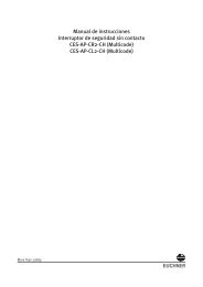
<strong>Safety</strong> <strong>Monitor</strong> block diagram:<br />
24 V 3.14<br />
<strong>Co</strong>nnections:<br />
0 V<br />
4.14<br />
1.13 1.14<br />
2.13 2.14<br />
1.13 0 V 24 V 2.13<br />
2.Y2 + 2.Y1 +<br />
output switching elements<br />
EDM/Start inputs<br />
Freigabe<br />
(Release)<br />
Freigabe<br />
(Release)<br />
Freigabe<br />
(Release)<br />
Freigabe<br />
(Release)<br />
Freigabe<br />
(Release)<br />
Freigabe<br />
(Release)<br />
Freigabe<br />
(Release)<br />
Freigabe<br />
(Release)<br />
Sicherheitsmonitor<br />
(<strong>Safety</strong> <strong>Monitor</strong>)<br />
+ - + -<br />
+ -<br />
Eingänge<br />
(Inputs)<br />
1.Y1 (EDM 1 / Start 1)<br />
2.Y1 (EDM 2 / Start 2)<br />
1.Y2 (EDM 3 / Start 3)<br />
2.Y2 (EDM 4 / Start 4)<br />
+<strong>AS</strong> I 1–<br />
<strong>AS</strong> I 1 +PWR– (max. 4A)<br />
+<strong>AS</strong> I 2–<br />
<strong>AS</strong> I 2 +PWR– (max. 4A)<br />
+ 1.Y1 + 1.Y2<br />
1.14 3.14 4.14 2.14<br />
EDM/Start inputs<br />
output switching elements<br />
Subject to reasonable modifications due to technical advances Id.-No.: 103336 Issue date - 24.10.2008 <strong>EUCHNER</strong> <strong>GmbH</strong> + <strong>Co</strong>. <strong>KG</strong><br />
17<br />
Kohlhammerstraße 16 • D-70771 Leinfelden-Echterdingen Tel. +49/711/75 97-0 • Fax. +49/711/753316
<strong>AS</strong>-i <strong>Safety</strong> <strong>Monitor</strong> <strong>for</strong> 2 <strong>AS</strong>-i <strong>circuits</strong><br />
Spezifications<br />
4.2 <strong>Co</strong>nsideration of failure probability according to IEC 61 508<br />
To allow calculation of failure probability <strong>for</strong> the entire system, the <strong>AS</strong>-i <strong>Safety</strong><br />
<strong>Monitor</strong> returns a component which depends on the maximum uninterrupted<br />
switch-on time of the output circuit(s).<br />
This results in the following table:<br />
Failure probability on request depending on switch-on time<br />
Switch-on time Total operating time PFD<br />
12 months 10 years < 9,25 x 10 -6<br />
The switch-on time describes the period of time until the safety function was requested,<br />
or the maximum period of time between two executed safety checks.<br />
During this check, safe shutdown is tested by actuating every safe sensor.<br />
The total operating time describes the safety system's service life from commissioning<br />
to disassembly; it is used as the basis <strong>for</strong> calculating the failure probability.<br />
Together with the failure probabilities of the other components used in the safety<br />
system (e.g. <strong>AS</strong>-i slaves) it is then possible to determine the overall failure probability.<br />
The resulting value can be used <strong>for</strong> categorising the safety system under<br />
the respective safety level in accordance with IEC 61 508.<br />
Probability of failure per hour<br />
Switch-on time Total operating time PFH<br />
12 months 10 years < 5,36 x 10 -9<br />
4.3 Scope of delivery<br />
The basic unit consists of:<br />
<strong>AS</strong>-i <strong>Safety</strong> <strong>Monitor</strong> <strong>for</strong> 2 <strong>AS</strong>-i <strong>circuits</strong>.<br />
The following accessories are available:<br />
Software CD with<br />
• <strong>AS</strong>IMON 3 G2 communication software <strong>for</strong> Microsoft® Windows Me/NT/<br />
2000/XP/Vista ®<br />
• System manual in PDF <strong>for</strong>mat (Adobe® Acrobat Reader® Version 5.x or<br />
newer is required <strong>for</strong> viewing the files)<br />
18<br />
Subject to reasonable modifications due to technical advances Id.-No.: 103336 Issue date - 24.10.2008 <strong>EUCHNER</strong> <strong>GmbH</strong> + <strong>Co</strong>. <strong>KG</strong><br />
Kohlhammerstraße 16 • D-70771 Leinfelden-Echterdingen Tel. +49/711/75 97-0 • Fax. +49/711/753316
<strong>AS</strong>-i <strong>Safety</strong> <strong>Monitor</strong> <strong>for</strong> 2 <strong>AS</strong>-i <strong>circuits</strong><br />
Installation<br />
5. Installation<br />
5.1 Dimensions<br />
Warning!<br />
<strong>Co</strong>ver the top of the <strong>AS</strong>-I <strong>Safety</strong> <strong>Monitor</strong> when doing any drilling work above the unit.<br />
No particles, especially metal chips, should be allowed to enter the housing, since this<br />
could cause a short circuit.<br />
In<strong>for</strong>mation!<br />
For additional in<strong>for</strong>mation, please refer to .<br />
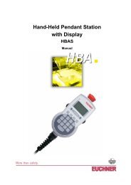
5.2 <strong>Co</strong>nnections<br />
5 ... 6 mm / PZ2<br />
10<br />
10<br />
0,8 Nm<br />
7 LB.IN<br />
2 x (0,5 ... 1,5) mm 2<br />
2 x (0,5 ... 1,5) mm 2<br />
AWG 2 x 24 ...12<br />
Attention!<br />
The <strong>AS</strong>-I power supply <strong>for</strong> the <strong>AS</strong>-I components must have isolation per IEC 60<br />
742 and be able to handle momentary power interruptions of up to 20 ms. The<br />
power supply <strong>for</strong> the 24 V supply must also have isolation per IEC 60 742 and be<br />
able to handle momentary power interruptions of up to 20 ms. The maximum output<br />
voltage of the power supply must also be less than 42 V in case of a fault.<br />
Subject to reasonable modifications due to technical advances Id.-No.: 103336 Issue date - 24.10.2008 <strong>EUCHNER</strong> <strong>GmbH</strong> + <strong>Co</strong>. <strong>KG</strong><br />
19<br />
Kohlhammerstraße 16 • D-70771 Leinfelden-Echterdingen Tel. +49/711/75 97-0 • Fax. +49/711/753316
<strong>AS</strong>-i <strong>Safety</strong> <strong>Monitor</strong> <strong>for</strong> 2 <strong>AS</strong>-i <strong>circuits</strong><br />
Installation<br />
5.3 Installing in the control cabinet<br />
The <strong>AS</strong>-I <strong>Safety</strong> <strong>Monitor</strong> is installed in the control cabinet on 35mm DIN rails per<br />
DIN EN 50 022.<br />
In<strong>for</strong>mation!<br />
The enclosure of the <strong>AS</strong>-i <strong>Safety</strong> <strong>Monitor</strong> is made of stainless steel. The unit is also suitable<br />
<strong>for</strong> exposed wall mounting.<br />
To install, place the unit on the upper edge of the DIN rail and then snap in the<br />
lower edge.<br />
[1]<br />
[2]<br />
+ -<br />
+ - + -<br />
5.4 Removing<br />
+ -<br />
+ - + -<br />
3<br />
1<br />
To remove, press the holding clamps [2] down using a screwdriver [1], press the<br />
unit firmly against the upper rail guide and lift out.<br />
2<br />
20<br />
Subject to reasonable modifications due to technical advances Id.-No.: 103336 Issue date - 24.10.2008 <strong>EUCHNER</strong> <strong>GmbH</strong> + <strong>Co</strong>. <strong>KG</strong><br />
Kohlhammerstraße 16 • D-70771 Leinfelden-Echterdingen Tel. +49/711/75 97-0 • Fax. +49/711/753316
<strong>AS</strong>-i <strong>Safety</strong> <strong>Monitor</strong> <strong>for</strong> 2 <strong>AS</strong>-i <strong>circuits</strong><br />
Installation<br />
5.5 Electrical <strong>Co</strong>nnection<br />
In<strong>for</strong>mation!<br />
Electrical connections are described in section <br />
5.6 <strong>Co</strong>mmissioning<br />
5.6.1 Supply voltage <strong>for</strong> <strong>AS</strong>-I <strong>Safety</strong> <strong>Monitor</strong><br />
Supply by <strong>AS</strong>-i<br />
Redundant: supply out of <strong>AS</strong>-i...<br />
...or out of 24 V aux. power ... or out of <strong>AS</strong>-i 2<br />
<strong>AS</strong>-i<br />
<strong>AS</strong>-i 24 V, 0 V<br />
<strong>AS</strong>-i 1 <strong>AS</strong>-i 2<br />
5.6.2 Duplicate address recognition<br />
5.6.2.1 <strong>AS</strong>-i Master without duplicate address recognition<br />
Gateway <strong>Monitor</strong> Power supply<br />
Power supply<br />
<strong>AS</strong>-i 1<br />
PWR 1<br />
<strong>AS</strong>-i 2 PWR 2<br />
Duplicate address recognition in the <strong>AS</strong>-i <strong>Safety</strong> <strong>Monitor</strong> active<br />
Subject to reasonable modifications due to technical advances Id.-No.: 103336 Issue date - 24.10.2008 <strong>EUCHNER</strong> <strong>GmbH</strong> + <strong>Co</strong>. <strong>KG</strong><br />
21<br />
Kohlhammerstraße 16 • D-70771 Leinfelden-Echterdingen Tel. +49/711/75 97-0 • Fax. +49/711/753316
<strong>AS</strong>-i <strong>Safety</strong> <strong>Monitor</strong> <strong>for</strong> 2 <strong>AS</strong>-i <strong>circuits</strong><br />
Installation<br />
5.6.2.2 <strong>AS</strong>-i Master with duplicate address recognition<br />
Gateway <strong>Monitor</strong> Power supply<br />
Power supply<br />
<strong>AS</strong>-i 1<br />
PWR 1<br />
PWR 2<br />
<strong>AS</strong>-i 2<br />
Duplicate address recognition in the <strong>AS</strong>-i Master active<br />
22<br />
Subject to reasonable modifications due to technical advances Id.-No.: 103336 Issue date - 24.10.2008 <strong>EUCHNER</strong> <strong>GmbH</strong> + <strong>Co</strong>. <strong>KG</strong><br />
Kohlhammerstraße 16 • D-70771 Leinfelden-Echterdingen Tel. +49/711/75 97-0 • Fax. +49/711/753316
<strong>AS</strong>-i <strong>Safety</strong> <strong>Monitor</strong> <strong>for</strong> 2 <strong>AS</strong>-i <strong>circuits</strong><br />
Installation<br />
5.6.3 Replacing the chip card<br />
Always turn off power be<strong>for</strong>e inserting or removing the card!<br />
[1]<br />
[2]<br />
[3] [4] [5]<br />
alt/old/ancien/<br />
vecchia/anciano<br />
[6] [7]<br />
neu/new/neuve/<br />
[8]<br />
Subject to reasonable modifications due to technical advances Id.-No.: 103336 Issue date - 24.10.2008 <strong>EUCHNER</strong> <strong>GmbH</strong> + <strong>Co</strong>. <strong>KG</strong><br />
23<br />
Kohlhammerstraße 16 • D-70771 Leinfelden-Echterdingen Tel. +49/711/75 97-0 • Fax. +49/711/753316
<strong>AS</strong>-i <strong>Safety</strong> <strong>Monitor</strong> <strong>for</strong> 2 <strong>AS</strong>-i <strong>circuits</strong><br />
Installation<br />
5.6.4 Local parameter setting of safe <strong>AS</strong>-i/Gateways and <strong>Monitor</strong>s<br />
Karte nicht <strong>for</strong>matiert<br />
/Card not <strong>for</strong>matted/<br />
Karte wird <strong>for</strong>matiert:<br />
/Formatting card /<br />
NEW CHIPCARD<br />
WILL BE FORMATTED<br />
DATA WILL BE<br />
SYNCHRONIZED<br />
Keine Aktion er<strong>for</strong>derlich<br />
/No action required/<br />
/Aucune action requise/<br />
/Nessuna azione richiesta/<br />
/Ninguna deción requrida/<br />
Unsichere Daten / Non-safe data/<br />
Données non-sécurisées/<br />
Dati non sicuri / Datos no seguros/<br />
Daten nicht kompatibel<br />
/Data not compatible/<br />
CHIPCARD NOT<br />
COMPATIBLE<br />
Daten kompatibel<br />
(Werkskonfiguration)<br />
/Data compatible (factory<br />
configuration)/<br />
DATA FROM<br />
CHIPCARD TAKEN<br />
Karte leer + <strong>for</strong>matiert<br />
/Card empty + <strong>for</strong>matted/<br />
Fehlermeldung:<br />
Daten werden übernommen: Daten werden synchronisiert: Keine Meldung<br />
/Error message/ /Data being acepted/<br />
/Data being synchronized/ /No message/<br />
CHIPCARD AND<br />
CHIPCARD FOUND<br />
DATA WILL<br />
BE SYNCHRONIZED<br />
Geräte+Chipdaten gleich<br />
/Device data+card data equal/<br />
Geräte+Chipdaten ungleich<br />
(Werkskonfiguration geändert)<br />
/Device+card data not equal<br />
(Factory configuartion changed)<br />
Fehlermeldung:<br />
/Error message/<br />
DATA<br />
DIFFERENT<br />
CARD->M<strong>AS</strong>TER<br />
M<strong>AS</strong>TER->CARD<br />
CONTINUE<br />
Karte löschen<br />
/Clear the card/<br />
/Supprimer carte/<br />
/Cancellare chipcard/<br />
/Borrar chip/<br />
Keine Aktion er<strong>for</strong>derlich<br />
/No action required/<br />
/Aucune action requise/<br />
/Nessuna azione richiesta/<br />
/Ninguna deción requrida/<br />
Keine Aktion er<strong>for</strong>derlich<br />
/No action required/<br />
/Aucune action requise/<br />
/Nessuna azione richiesta/<br />
/Ninguna deción requrida/<br />
Keine Aktion er<strong>for</strong>derlich<br />
/No action required/<br />
/Aucune action requise/<br />
/Nessuna azione richiesta/<br />
/Ninguna deción requrida/<br />
Daten kopieren<br />
KARTE->M<strong>AS</strong>TER oder<br />
M<strong>AS</strong>TER->KARTE<br />
<strong>Co</strong>py data CARD->M<strong>AS</strong>TER<br />
or M<strong>AS</strong>TER->CARD<br />
<strong>Co</strong>pier données Carte->Maître ou<br />
Maître-Carte<br />
<strong>Co</strong>piare dati Chipcard->Master o<br />
copiare dati Master->Chipcard<br />
<strong>Co</strong>piar dates Chip->Maestro o<br />
Maestro ->Chip<br />
24<br />
Subject to reasonable modifications due to technical advances Id.-No.: 103336 Issue date - 24.10.2008 <strong>EUCHNER</strong> <strong>GmbH</strong> + <strong>Co</strong>. <strong>KG</strong><br />
Kohlhammerstraße 16 • D-70771 Leinfelden-Echterdingen Tel. +49/711/75 97-0 • Fax. +49/711/753316
<strong>AS</strong>-i <strong>Safety</strong> <strong>Monitor</strong> <strong>for</strong> 2 <strong>AS</strong>-i <strong>circuits</strong><br />
Installation<br />
Sichere Daten auf der<br />
Chipkarte nicht kompatibel<br />
zum Gerät<br />
/Safe data on the chip card<br />
not compatible to the device/<br />
Fehlermeldung:<br />
/Error message/<br />
CHIPCARD NOT<br />
COMPATIBLE<br />
Karte löschen<br />
/Clear the card/<br />
/Supprimer carte/<br />
/Cancellare chipcard/<br />
/Borrar chip/<br />
Sichere Daten / Safe data/<br />
Données sécurisées/<br />
Dati sicuri / Datos seguros<br />
Keine validierte Konfiguration im<br />
Gerät + Chipkarte<br />
/No validated configuration in<br />
the device + chip card/<br />
Daten werden synchronisiert: Daten werden synchronisiert:<br />
/Data being synchronized/ /Data being synchronized/<br />
ERROR.<br />
CHIPCARD FOUND<br />
SAFETY DATA WILL<br />
BE SYNCHRONIZED<br />
Validierte Konfiguration im<br />
Gerät, Chipkarte leer<br />
/Validated configuration<br />
in the device, chip card empty/<br />
CHIPCARD FOUND<br />
SAFETY DATA WILL<br />
BE SYNCHRONIZED<br />
Gerät enthält keine validierte<br />
Konfiguration<br />
/No validated configuration in<br />
the device/<br />
Stamm-/Vollständige<br />
Konfiguartion auf der Chipkarte<br />
/Master configuration or<br />
complete configuration on the<br />
card<br />
Datenfreigabe per<br />
Release-<strong>Co</strong>de notwendig:<br />
/Data release via release code<br />
required/<br />
COPY BANK A TO<br />
MONITOR<br />
...<br />
RELE<strong>AS</strong>E CODE:<br />
1BDF<br />
---------------<br />
TYPE CODE<br />
1BDF OK<br />
Stamm-/Vollständige<br />
Konfiguartion auf der Chipkarte<br />
/Master configuration or<br />
complete configuration on the<br />
card<br />
Gerät enthält validierte<br />
Konfiguration<br />
/There is a validated<br />
configuration on the card<br />
Beide Konfigurationen gleich/<br />
Both configurations identical<br />
Keine Meldung<br />
/No message/<br />
Stamm-/Vollständige<br />
Konfiguartion auf der Chipkarte<br />
enthalten<br />
/Master configuration or<br />
complete configuration on the<br />
card<br />
Gerät enthält validierte<br />
Konfiguration, Daten ungleich<br />
/There is a validated<br />
configuration on the card, data<br />
not equal<br />
Beide Konfigurationen ungleich/<br />
Both configurations not equal<br />
Fehlermeldung:<br />
/Error message/<br />
CHIPCARD AND<br />
SAFETY DATA<br />
DIFFERENT.<br />
DELETE CHIPCARD<br />
OR SAFETY DATA<br />
Keine Aktion er<strong>for</strong>derlich<br />
/No action required/<br />
/Aucune action requise/<br />
/Nessuna azione richiesta/<br />
/Ninguna deción requrida/<br />
Keine Aktion er<strong>for</strong>derlich<br />
/No action required/<br />
/Aucune action requise/<br />
/Nessuna azione richiesta/<br />
/Ninguna deción requrida/<br />
Konfiguration per<br />
Release-<strong>Co</strong>de freigeben<br />
/Validate the configuration<br />
via release code/<br />
/Respecter les indications<br />
de sécurité exposées dans<br />
le manuel <strong>AS</strong>IMON<br />
/Osservare le istruzioni di<br />
sicurezza riportate nel<br />
manuale <strong>AS</strong>IMON<br />
/Habilitar la configuratión<br />
con el código de liberatión/<br />
Keine Aktion er<strong>for</strong>derlich<br />
/No action required/<br />
/Aucune action requise/<br />
/Nessuna azione richiesta/<br />
/Ninguna deción requrida/<br />
Daten löschen<br />
/Clear data/<br />
/Supprimer données /<br />
/Cancellare dati<br />
/Borrar datos<br />
For further in<strong>for</strong>mation see manual, section <br />
Subject to reasonable modifications due to technical advances Id.-No.: 103336 Issue date - 24.10.2008 <strong>EUCHNER</strong> <strong>GmbH</strong> + <strong>Co</strong>. <strong>KG</strong><br />
25<br />
Kohlhammerstraße 16 • D-70771 Leinfelden-Echterdingen Tel. +49/711/75 97-0 • Fax. +49/711/753316
<strong>AS</strong>-i <strong>Safety</strong> <strong>Monitor</strong> <strong>for</strong> 2 <strong>AS</strong>-i <strong>circuits</strong><br />
Installation<br />
5.6.5 Replacing a defective safety-configured <strong>AS</strong>-i slave<br />
The new slave must be able to send teaching codes and must have the same address<br />
as the old one. Only one missing slave is allowed!<br />
[1]<br />
[2]<br />
ESC/Service<br />
(3 seconds)<br />
CONNECT<br />
NEW SLAVE 17<br />
THEN PRESS<br />
SERVICE<br />
[3]<br />
[4]<br />
ESC/Service<br />
(3 seconds)<br />
26<br />
Subject to reasonable modifications due to technical advances Id.-No.: 103336 Issue date - 24.10.2008 <strong>EUCHNER</strong> <strong>GmbH</strong> + <strong>Co</strong>. <strong>KG</strong><br />
Kohlhammerstraße 16 • D-70771 Leinfelden-Echterdingen Tel. +49/711/75 97-0 • Fax. +49/711/753316
<strong>AS</strong>-i <strong>Safety</strong> <strong>Monitor</strong> <strong>for</strong> 2 <strong>AS</strong>-i <strong>circuits</strong><br />
Installation<br />
5.7 Safe configuration using <strong>AS</strong>IMON 3 G2<br />
<strong>AS</strong>IMON 3 G2<br />
Software<br />
Start<br />
Be<strong>for</strong>e commissioning the safety unit, put the gateway into operation!<br />
<strong>AS</strong>IMON 3 G2 Software<br />
Change the preset password during the first use of the device (<strong>Monitor</strong>/change password)!<br />
<strong>AS</strong>IMON 3 G2 Software<br />
Create the desired configuration.<br />
<strong>AS</strong>IMON 3 G2 Software<br />
Download the configuration with MONITOR / PC-> MONITOR into the device. Enter the password <strong>for</strong><br />
this purpose.<br />
<strong>AS</strong>IMON 3 G2 Software<br />
You can acknowledge the request TEACH CODE SEQUENCES? selecting "Yes", or you can do it later<br />
via display selecting "No".<br />
<strong>AS</strong>IMON 3 G2 Software<br />
Check the configuration log (respect instructions in of the <strong>AS</strong>IMON manual!).<br />
<strong>AS</strong>IMON 3 G2 Software<br />
Validate the configuration with MONITOR –> VALIDATION.<br />
<strong>AS</strong>IMON 3 G2 Software<br />
Start the monitor with MONITOR–> START.<br />
Subject to reasonable modifications due to technical advances Id.-No.: 103336 Issue date - 24.10.2008 <strong>EUCHNER</strong> <strong>GmbH</strong> + <strong>Co</strong>. <strong>KG</strong><br />
27<br />
Kohlhammerstraße 16 • D-70771 Leinfelden-Echterdingen Tel. +49/711/75 97-0 • Fax. +49/711/753316
☺ Press OK <strong>for</strong> Menu<br />
Output Circuit<br />
1:ON 2:OFF<br />
<strong>AS</strong>-i <strong>Safety</strong> <strong>Monitor</strong> <strong>for</strong> 2 <strong>AS</strong>-i <strong>circuits</strong><br />
Installation<br />
<strong>AS</strong>IMON 3 G2 Software<br />
☺ Press OK <strong>for</strong> Menu<br />
Output Circuit<br />
1:ON 2:OFF<br />
The device is in the protected mode now.<br />
Adjust the configuration in the <strong>AS</strong>-i Master, when you address the safety monitor with<br />
the help of <strong>AS</strong>IMON 3 G2 software!<br />
Please consider notes on safety in the software manual <strong>AS</strong>IMON 3 G2!<br />
28<br />
Subject to reasonable modifications due to technical advances Id.-No.: 103336 Issue date - 24.10.2008 <strong>EUCHNER</strong> <strong>GmbH</strong> + <strong>Co</strong>. <strong>KG</strong><br />
Kohlhammerstraße 16 • D-70771 Leinfelden-Echterdingen Tel. +49/711/75 97-0 • Fax. +49/711/753316
<strong>AS</strong>-i <strong>Safety</strong> <strong>Monitor</strong> <strong>for</strong> 2 <strong>AS</strong>-i <strong>circuits</strong><br />
Maintenance<br />
6. Maintenance<br />
6.1 Checking <strong>for</strong> safe turn-off<br />
The safety representative is responsible <strong>for</strong> checking flawless function of the <strong>AS</strong>-i<br />
<strong>Safety</strong> <strong>Monitor</strong> within the safety system.<br />
Safe turn-off when an associated safe sensor or switch is triggered must be<br />
checked at least once a year.<br />
Attention!<br />
To do this, actuate each safe <strong>AS</strong>-i slave and observe the switching behavior of<br />
the output <strong>circuits</strong> of the <strong>AS</strong>-i <strong>Safety</strong> <strong>Monitor</strong>.<br />
Attention!<br />
Note the maximum turn-on duration and the overall turn-on operating duration.<br />
These values depend on the PFD value selected (see Section “Probability of<br />
Failure on Demand per IEC 61 508”).<br />
When the maximum turn-on duration is reached (three, six or twelve months),<br />
check the complete safety system and its proper function.<br />
When the total operating time (10 years) has been reached, the device must be<br />
returned to the manufacturer to check <strong>for</strong> proper function.<br />
Subject to reasonable modifications due to technical advances Id.-No.: 103336 Issue date - 24.10.2008 <strong>EUCHNER</strong> <strong>GmbH</strong> + <strong>Co</strong>. <strong>KG</strong><br />
29<br />
Kohlhammerstraße 16 • D-70771 Leinfelden-Echterdingen Tel. +49/711/75 97-0 • Fax. +49/711/753316
<strong>AS</strong>-i <strong>Safety</strong> <strong>Monitor</strong> <strong>for</strong> 2 <strong>AS</strong>-i <strong>circuits</strong><br />
Electrical connection<br />
7. Electrical connection<br />
7.1 Overview of terminals, indicators and operating elements<br />
7.1.1 103303<br />
[3]<br />
[7]<br />
[4]<br />
[3]<br />
[5]<br />
[6]<br />
+ -<br />
+ - + -<br />
[7]<br />
[1]<br />
[2]<br />
5 ... 6 mm / PZ2<br />
10<br />
10<br />
0,8 Nm<br />
7 LB.IN<br />
2 x (0,5 ... 1,5) mm 2<br />
2 x (0,5 ... 1,5) mm 2<br />
AWG 2 x 24 ...12<br />
Legend:<br />
[1] Chip card slot<br />
[2] RS 232 diagnostics port 1<br />
[3] LEDs<br />
[4] LC display<br />
[5] Buttons<br />
[6] Terminals: Supply voltage and <strong>AS</strong>-i circuit<br />
[7] Terminals: <strong>Safety</strong> <strong>Monitor</strong><br />
1. Only together with <strong>AS</strong>IMON 3 G2 Software or <strong>AS</strong>-i <strong>Co</strong>ntrol Tools<br />
30<br />
Subject to reasonable modifications due to technical advances Id.-No.: 103336 Issue date - 24.10.2008 <strong>EUCHNER</strong> <strong>GmbH</strong> + <strong>Co</strong>. <strong>KG</strong><br />
Kohlhammerstraße 16 • D-70771 Leinfelden-Echterdingen Tel. +49/711/75 97-0 • Fax. +49/711/753316
<strong>AS</strong>-i <strong>Safety</strong> <strong>Monitor</strong> <strong>for</strong> 2 <strong>AS</strong>-i <strong>circuits</strong><br />
Electrical connection<br />
7.2 <strong>AS</strong>-i bus connection<br />
Blue<br />
<strong>AS</strong>-i-<br />
Brown<br />
<strong>AS</strong>-i+<br />
Blau<br />
<strong>AS</strong>-i-<br />
Braun<br />
<strong>AS</strong>-i+<br />
Yellow <strong>AS</strong>i ribbon cable 2-conductor <strong>AS</strong>-i round cable<br />
(Recommended: flexible power cable<br />
H05VV-F2x1,5 per DIN VDE 0281)<br />
In<strong>for</strong>mation!<br />
Electrical work is to be per<strong>for</strong>med only by electrical technicians.<br />
7.3 In<strong>for</strong>mation about the device types<br />
In<strong>for</strong>mation!<br />
A listing of the individual devices and their features can be found in section .<br />
7.4 <strong>AS</strong>-i and power supply terminal assignments<br />
In<strong>for</strong>mation!<br />
The cable indicated by hatching must not have slaves or repeaters connected to<br />
it.<br />
The yellow cable must not have <strong>AS</strong>-i power suppliers or additional masters connected<br />
to it.<br />
In<strong>for</strong>mation!<br />
The function ground should be made with as short a cable as possible to ensure good<br />
EMC characteristics.<br />
Attention!<br />
The <strong>AS</strong>-I power supply <strong>for</strong> the <strong>AS</strong>-I components must have isolation per IEC 60<br />
742 and be able to handle momentary power interruptions of up to 20 ms. The<br />
power supply <strong>for</strong> the 24 V supply must also have isolation per IEC 60 742 and be<br />
able to handle momentary power interruptions of up to 20 ms. The maximum output<br />
voltage of the power supply must also be less than 42 V in case of a fault.<br />
Subject to reasonable modifications due to technical advances Id.-No.: 103336 Issue date - 24.10.2008 <strong>EUCHNER</strong> <strong>GmbH</strong> + <strong>Co</strong>. <strong>KG</strong><br />
31<br />
Kohlhammerstraße 16 • D-70771 Leinfelden-Echterdingen Tel. +49/711/75 97-0 • Fax. +49/711/753316
<strong>AS</strong>-i <strong>Safety</strong> <strong>Monitor</strong> <strong>for</strong> 2 <strong>AS</strong>-i <strong>circuits</strong><br />
Electrical connection<br />
7.4.1 Electrical connection 103303<br />
+ - + -<br />
+ -<br />
+<strong>AS</strong>I 1–<br />
<strong>AS</strong>I 1 +PWR– (max. 4A)<br />
+<strong>AS</strong>I 2–<br />
<strong>AS</strong>I + 2 +PWR– (max. 4A)<br />
Terminal<br />
Signal / Description<br />
+<strong>AS</strong>I 1– <strong>Co</strong>nnection to <strong>AS</strong>-i Circuit 1<br />
+<strong>AS</strong>I 2– <strong>Co</strong>nnection to <strong>AS</strong>-i Circuit 2<br />
<strong>AS</strong>I 1 +PWR– Supply voltage <strong>for</strong> <strong>AS</strong>-i Circuit 1 (max. 4 A)<br />
<strong>AS</strong>I 2 +PWR– Supply voltage <strong>for</strong> <strong>AS</strong>-i Circuit 2 (max. 4 A)<br />
FG<br />
Function ground<br />
In<strong>for</strong>mation!<br />
<strong>AS</strong>-i Circuits 1 and 2 are powered by separate power supplies.<br />
32<br />
Subject to reasonable modifications due to technical advances Id.-No.: 103336 Issue date - 24.10.2008 <strong>EUCHNER</strong> <strong>GmbH</strong> + <strong>Co</strong>. <strong>KG</strong><br />
Kohlhammerstraße 16 • D-70771 Leinfelden-Echterdingen Tel. +49/711/75 97-0 • Fax. +49/711/753316
<strong>AS</strong>-i <strong>Safety</strong> <strong>Monitor</strong> <strong>for</strong> 2 <strong>AS</strong>-i <strong>circuits</strong><br />
Electrical connection<br />
7.5 Diagnostics interface<br />
The service and diagnostics interface (in conjunction with <strong>AS</strong>-i <strong>Co</strong>ntrol Tools or<br />
<strong>AS</strong>IMON 3 G2 software) is used <strong>for</strong> communication between the PC and the unit.<br />
7.5.1 103303<br />
The service and diagnostics interface in these devices is configured as a mini<br />
DIN-6 female and it is placed on the front plate, on the left hand side.<br />
7.6 Chip card<br />
The configuration is stored in a fixed installed EEPROM and can be overwritten<br />
by the chip card. The chip card does not have to be inserted in operation.<br />
Warning!<br />
Power must always be turned off when removing or inserting the chip card!<br />
Subject to reasonable modifications due to technical advances Id.-No.: 103336 Issue date - 24.10.2008 <strong>EUCHNER</strong> <strong>GmbH</strong> + <strong>Co</strong>. <strong>KG</strong><br />
33<br />
Kohlhammerstraße 16 • D-70771 Leinfelden-Echterdingen Tel. +49/711/75 97-0 • Fax. +49/711/753316
<strong>AS</strong>-i <strong>Safety</strong> <strong>Monitor</strong> <strong>for</strong> 2 <strong>AS</strong>-i <strong>circuits</strong><br />
Electrical connection<br />
7.7 Release <strong>circuits</strong><br />
7.7.1 Wiring overview of <strong>Safety</strong> <strong>Monitor</strong> 103303<br />
1.13 0 V 24 V 2.13<br />
2.Y2 + 2.Y1 +<br />
Aux<br />
1.Y1<br />
2.Y1<br />
1.Y2<br />
2.Y2<br />
K1<br />
K3<br />
K2<br />
K4<br />
+ 1.Y1 + 1.Y2<br />
1.14 3.14 4.14 2.14<br />
1.Y1 (EDM 1/Start 1), 2.Y1 (EDM 2/Start 2), 1.Y2 (EDM 3/Start 3),<br />
2.Y2 (EDM 4/Start 4)<br />
The safety unit provides 4 inputs. The EDM & START inputs can be defined freely.<br />
The inputs may not be connected to other potentials, but rather only directly or<br />
through potential-free switches to + (<strong>for</strong> EDM/START).<br />
Switching current static 4 mA at 24 V, dynamic 30 mA at 24 V (T=100 µs).<br />
3.14, 4.14<br />
Semiconductor outputs. Max. contact load: 0.5 A DC-13 at 30 V.<br />
1.14, 2.14; 1.13, 2.13<br />
Potential-free relay contacts. <strong>Safety</strong> relay with one contact set <strong>for</strong> read-back. Max.<br />
contact load: 3 A AC-15 at 30 V, 3 A DC-13 at 30 V.<br />
0V, 24V<br />
Semiconductor outputs are powered by separate 24 V DC.<br />
+ (<strong>for</strong> EDM/Start)<br />
Output supply, powered by <strong>AS</strong>-i. May not be connected to other potentials, but<br />
rather only directly or through potential-free switches to one of the EDM or START<br />
inputs. Voltage 30 ... 15 V DC .<br />
34<br />
Subject to reasonable modifications due to technical advances Id.-No.: 103336 Issue date - 24.10.2008 <strong>EUCHNER</strong> <strong>GmbH</strong> + <strong>Co</strong>. <strong>KG</strong><br />
Kohlhammerstraße 16 • D-70771 Leinfelden-Echterdingen Tel. +49/711/75 97-0 • Fax. +49/711/753316
<strong>AS</strong>-i <strong>Safety</strong> <strong>Monitor</strong> <strong>for</strong> 2 <strong>AS</strong>-i <strong>circuits</strong><br />
Electrical connection<br />
7.8 Indicators and operating elements<br />
7.8.1 LED indicators – <strong>Monitor</strong> 103303<br />
chip card<br />
fault<br />
ready<br />
U <strong>AS</strong>-i 1<br />
U <strong>AS</strong>-i 2<br />
The LED’s on the front panel of the device indicate:<br />
power<br />
The monitor is receiving sufficient power.<br />
fault<br />
LED on:<br />
LED flashing:<br />
<strong>Co</strong>mmunications fault on the <strong>AS</strong>-i cable<br />
At least 1 OSSD flashing red<br />
ready<br />
LED on: Startup/restart block active /<br />
LED flashing: External test required<br />
U <strong>AS</strong>-i 1 / U <strong>AS</strong>-i 2<br />
<strong>AS</strong>-i 1 / <strong>AS</strong>-i 2 receiving sufficient power<br />
Subject to reasonable modifications due to technical advances Id.-No.: 103336 Issue date - 24.10.2008 <strong>EUCHNER</strong> <strong>GmbH</strong> + <strong>Co</strong>. <strong>KG</strong><br />
35<br />
Kohlhammerstraße 16 • D-70771 Leinfelden-Echterdingen Tel. +49/711/75 97-0 • Fax. +49/711/753316
<strong>AS</strong>-i <strong>Safety</strong> <strong>Monitor</strong> <strong>for</strong> 2 <strong>AS</strong>-i <strong>circuits</strong><br />
Electrical connection<br />
7.8.2 LED indicators safety unit in 103303<br />
1.13<br />
2.Y2<br />
0 V 24 V<br />
+ 2.Y1<br />
2.13<br />
+<br />
Aux<br />
1.Y1<br />
2.Y1<br />
K1<br />
K3<br />
1.Y2<br />
2.Y2<br />
K2<br />
K4<br />
+ 1.Y1<br />
1.14 3.14<br />
+<br />
4.14<br />
1.Y2<br />
2.14<br />
The LED’s on the safety unit indicate:<br />
Aux<br />
24 V supply <strong>for</strong> the semiconductor outputs is present.<br />
1Y.1, 1Y2, 2Y.1, 2Y.2<br />
Input 1.Y1 (EDM 1/Start 1), 2.Y1 (EDM 2/Start 2), 1.Y2 (EDM 3/Start 3),<br />
2.Y2 (EDM 4/Start 4) is turned on.<br />
K1, K2<br />
<strong>Co</strong>ntact sets 1.13, 1.14 (K1) resp. 2.13, 2.14 (K2) closed.<br />
K3, K4<br />
Auxiliary voltage is present on the semiconductor output 3.14 (K3) resp.14 (K4).<br />
36<br />
Subject to reasonable modifications due to technical advances Id.-No.: 103336 Issue date - 24.10.2008 <strong>EUCHNER</strong> <strong>GmbH</strong> + <strong>Co</strong>. <strong>KG</strong><br />
Kohlhammerstraße 16 • D-70771 Leinfelden-Echterdingen Tel. +49/711/75 97-0 • Fax. +49/711/753316
<strong>AS</strong>-i <strong>Safety</strong> <strong>Monitor</strong> <strong>for</strong> 2 <strong>AS</strong>-i <strong>circuits</strong><br />
Electrical connection<br />
7.8.3 Buttons<br />
The buttons are used <strong>for</strong> the following:<br />
⇑<br />
Navigation in extended mode<br />
⇓<br />
OK<br />
ESC/Service<br />
Change to extended mode<br />
For teaching the code table <strong>for</strong> a new safe slave, when exactly one<br />
safe slave is being replaced, and <strong>for</strong> unlocking the <strong>Safety</strong> <strong>Monitor</strong>.<br />
This button is also used to exit extended mode.<br />
For additional in<strong>for</strong>mation see:<br />
•
<strong>AS</strong>-i <strong>Safety</strong> <strong>Monitor</strong> <strong>for</strong> 2 <strong>AS</strong>-i <strong>circuits</strong><br />
Function and startup of the <strong>Safety</strong> <strong>Monitor</strong><br />
8. Function and startup of the <strong>Safety</strong> <strong>Monitor</strong><br />
<strong>Co</strong>nfiguration and startup of the <strong>AS</strong>-i <strong>Safety</strong> <strong>Monitor</strong> is accomplished using a PC/<br />
Notebook and the <strong>AS</strong>IMON 3 G2 configuration software.<br />
The operating language of the device can be set <strong>for</strong> the respective country (see<br />
section ).<br />
In<strong>for</strong>mation!<br />
The description of the <strong>AS</strong>IMON 3 G2 software and startup of the <strong>AS</strong>-i <strong>Safety</strong> <strong>Monitor</strong><br />
can be found in the manual “<strong>AS</strong>IMON 3 G2 <strong>AS</strong>-i <strong>Safety</strong> <strong>Monitor</strong> <strong>Co</strong>nfiguration Software<br />
<strong>for</strong> Microsoft®-Windows®“.<br />
The software manual is an important component of the operating manual <strong>for</strong> the <strong>AS</strong>-i<br />
<strong>Safety</strong> <strong>Monitor</strong>. It is not possible to configure and start up the <strong>AS</strong>-i <strong>Safety</strong> <strong>Monitor</strong> without<br />
the <strong>AS</strong>IMON 3 G2 software.<br />
<strong>Co</strong>nfiguration may be per<strong>for</strong>med only by a safety authorized person. All safety-related<br />
commands are password protected.<br />
8.1 Powering up the device<br />
As soon as supply voltage is present on the device an internal system test is<br />
started. This operating state is indicated by lighting of the upper LED row.<br />
8.2 <strong>Co</strong>nfiguration of the safety functions<br />
The device can be configured in several ways:<br />
1. Using <strong>AS</strong>IMON 3 G2 software<br />
The <strong>AS</strong>IMON 3 G2 software represents the most universal method of configuring<br />
the <strong>Safety</strong> <strong>Monitor</strong>. Here the behavior of the <strong>Safety</strong> <strong>Monitor</strong> can be<br />
determined by linking various monitoring modules. After being sent to the<br />
<strong>Safety</strong> <strong>Monitor</strong>, this configuration is verified and can then be validated.<br />
For additional in<strong>for</strong>mation, refer to the separate manual <strong>for</strong> the<br />
<strong>AS</strong>IMON 3 G2 configuration software.<br />
2. Using a chip card with the master configuration<br />
<strong>Co</strong>nfigurations stored on the chip card, which are validated but which do not<br />
contain any code sequences, can be sent to the device. The code<br />
sequences must then be taught to the corresponding safety <strong>AS</strong>-i slaves.<br />
This procedure is useful when you want to use a safety program in several<br />
safety monitors without any changes.<br />
In<strong>for</strong>mation!<br />
For additional in<strong>for</strong>mation refer to .<br />
3. Using a chip card with complete configuration<br />
38<br />
Subject to reasonable modifications due to technical advances Id.-No.: 103336 Issue date - 24.10.2008 <strong>EUCHNER</strong> <strong>GmbH</strong> + <strong>Co</strong>. <strong>KG</strong><br />
Kohlhammerstraße 16 • D-70771 Leinfelden-Echterdingen Tel. +49/711/75 97-0 • Fax. +49/711/753316
<strong>AS</strong>-i <strong>Safety</strong> <strong>Monitor</strong> <strong>for</strong> 2 <strong>AS</strong>-i <strong>circuits</strong><br />
Function and startup of the <strong>Safety</strong> <strong>Monitor</strong><br />
In contrast to the master configuration, the complete configuration also contains<br />
the code sequences <strong>for</strong> all included slaves. Sending the complete configuration<br />
from the chip card to the <strong>Safety</strong> <strong>Monitor</strong> can make replacement of<br />
the device enormously simpler and faster.<br />
In<strong>for</strong>mation!<br />
For additional in<strong>for</strong>mation refer to .<br />
8.2.1 Description of configuration using <strong>AS</strong>IMON 3 G2 software<br />
The following description represents a short guide to configuring the <strong>AS</strong>-i <strong>Safety</strong><br />
<strong>Monitor</strong>. For a detailed description of the <strong>AS</strong>IMON 3 G2 software, refer to the corresponding<br />
manual <strong>for</strong> the <strong>AS</strong>IMON 3 G2 configuration software.<br />
The <strong>AS</strong>IMON 3 G2 software is responsible <strong>for</strong> the following:<br />
• <strong>Co</strong>nfiguring the <strong>AS</strong>-i <strong>Safety</strong> <strong>Monitor</strong><br />
• Documenting the device configuration<br />
• Starting up the <strong>AS</strong>-i <strong>Safety</strong> <strong>Monitor</strong><br />
• Diagnosing the <strong>AS</strong>-i <strong>Safety</strong> <strong>Monitor</strong><br />
In<strong>for</strong>mation!<br />
The description of the <strong>AS</strong>IMON 3 G2 program can be found in the separate software<br />
manual.<br />
Proceed as follows:<br />
• Install the program on your PC.<br />
• Apply power to the <strong>AS</strong>-i <strong>Safety</strong> <strong>Monitor</strong><br />
In<strong>for</strong>mation!<br />
To prevent ESD damage, we recommend grounding at an appropriate location be<strong>for</strong>e<br />
plugging in the interface cable to the <strong>Safety</strong> <strong>Monitor</strong>.<br />
• <strong>Co</strong>nnection of monitors with a RS 232 diagnostics interface<br />
• To connect, plug the diagnostic cable end with the PS2 connector into<br />
the socket of the diagnostic interface (RS 232) of the monitor and the<br />
other end with the 9-pin Sub-D socket connector to a free COM port<br />
(serial RS232 interface) on your PC (see section 2.1.2 “<strong>Co</strong>nnection<br />
between the <strong>AS</strong>-i <strong>Safety</strong> <strong>Monitor</strong> and the PC" in the software manual).<br />
• <strong>Co</strong>nfigure the <strong>AS</strong>-i <strong>Safety</strong> <strong>Monitor</strong> and start it up as described in the software<br />
manual.<br />
Attention!<br />
Be<strong>for</strong>e starting up the device you must adapt the device configuration to your<br />
application. This means configuring the <strong>AS</strong>-i <strong>Safety</strong> <strong>Monitor</strong> according to the software<br />
manual so that the location to be protected is in fact protected by the device.<br />
Subject to reasonable modifications due to technical advances Id.-No.: 103336 Issue date - 24.10.2008 <strong>EUCHNER</strong> <strong>GmbH</strong> + <strong>Co</strong>. <strong>KG</strong><br />
39<br />
Kohlhammerstraße 16 • D-70771 Leinfelden-Echterdingen Tel. +49/711/75 97-0 • Fax. +49/711/753316
<strong>AS</strong>-i <strong>Safety</strong> <strong>Monitor</strong> <strong>for</strong> 2 <strong>AS</strong>-i <strong>circuits</strong><br />
Function and startup of the <strong>Safety</strong> <strong>Monitor</strong><br />
8.2.2 Description of configuration using chip card with master configuration<br />
Generating a master configuration:<br />
• Generate a configuration using the <strong>AS</strong>IMON 3 G2 software<br />
• Load the configuration into the device<br />
• Release (validate) the configuration, but do not teach the code sequences<br />
• The code sequences will be taught on the physical <strong>AS</strong>-i circuit<br />
Attention!<br />
<strong>Safety</strong> advisory:<br />
Ensure that the chip card contains the configuration intended <strong>for</strong> and released <strong>for</strong><br />
the application!<br />
This can be done by comparing the release codes on the display (section ):<br />
The safety representative who generated and validated the release code stores<br />
the release code <strong>for</strong> the master configuration and approves use of the configuration<br />
<strong>for</strong> specific equipment.<br />
The person per<strong>for</strong>ming the startup reads out the release code on the display<br />
be<strong>for</strong>e teaching the code and compares it with the release code stored and<br />
approved <strong>for</strong> the equipment.<br />
After the chip card has been used to load the configuration into the device, the<br />
safety functions of the device must be checked in the equipment.<br />
Checking of the release code and testing the system must be documented in writing<br />
and is part of the system documentation.<br />
8.2.3 <strong>Co</strong>nfiguration using a chip card with complete configuration<br />
The chip card contains the complete configuration if:<br />
• An empty chip cared is plugged into an <strong>AS</strong>-i <strong>Safety</strong> <strong>Monitor</strong> which already<br />
contains a complete configuration, or<br />
• The chip card is already inserted while the configuration is being written into<br />
the device using <strong>AS</strong>IMON 3 G2 software and be<strong>for</strong>e validating the code<br />
sequences.<br />
If the <strong>AS</strong>-i <strong>Safety</strong> <strong>Monitor</strong> needs to be replaced, the stored configuration can be<br />
transferred by simply plugging the chip card from the old device into the new one.<br />
40<br />
Subject to reasonable modifications due to technical advances Id.-No.: 103336 Issue date - 24.10.2008 <strong>EUCHNER</strong> <strong>GmbH</strong> + <strong>Co</strong>. <strong>KG</strong><br />
Kohlhammerstraße 16 • D-70771 Leinfelden-Echterdingen Tel. +49/711/75 97-0 • Fax. +49/711/753316
<strong>AS</strong>-i <strong>Safety</strong> <strong>Monitor</strong> <strong>for</strong> 2 <strong>AS</strong>-i <strong>circuits</strong><br />
Function and startup of the <strong>Safety</strong> <strong>Monitor</strong><br />
Attention!<br />
<strong>Safety</strong> advisory:<br />
Power must always be turned off when removing or inserting the chip card!<br />
Ensure that the chip card contains the configuration intended <strong>for</strong> and released <strong>for</strong><br />
the application!<br />
This can be done by comparing the release codes on the display (section):<br />
The safety representative who generated and validated the release code stores<br />
the release code <strong>for</strong> the master configuration and approves use of the configuration<br />
<strong>for</strong> specific equipment.<br />
The person per<strong>for</strong>ming the startup reads out the release code on the display<br />
be<strong>for</strong>e starting the equipment and compares it with the release code stored and<br />
approved <strong>for</strong> the equipment.<br />
After the chip card has been used to load the configuration into the device, the<br />
safety functions of the device must be checked in the equipment.<br />
Checking of the release code and testing the system must be documented in writing<br />
and is part of the system documentation.<br />
8.3 <strong>Safety</strong>-relevant documentation of the application<br />
In<strong>for</strong>mation!<br />
The detailed description of the safety-relevant documentation of the configuration <strong>for</strong><br />
your application can be found in the separate software manual.<br />
Proceed as follows:<br />
• Create the configuration of the <strong>AS</strong>-i <strong>Safety</strong> <strong>Monitor</strong> <strong>for</strong> your application.<br />
• Validate the configuration (done by the safety supervisor).<br />
• Print out the final configuration protocol and optionally the configuration overview<br />
(see Section 5.8 "<strong>Co</strong>nfiguration documentation" in the software manual).<br />
• Sign the final configuration protocol (done by the safety supervisor).<br />
• Take the protocol <strong>for</strong> the safety-relevant documentation <strong>for</strong> your application<br />
(machine documentation) and keep it in a safe place.<br />
8.4 Diagnostic data<br />
In<strong>for</strong>mation!<br />
A detailed description of the setting <strong>for</strong> diagnostics mode is described in the section<br />
“Setting diagnostics type” in the separate manual "<strong>AS</strong>-i <strong>3.0</strong> <strong>Co</strong>mmand Inteface".<br />
Diagnostics data can be obtained in any of 4 ways:<br />
• Display<br />
• Diagnostics through <strong>AS</strong>-i (see section ).<br />
Subject to reasonable modifications due to technical advances Id.-No.: 103336 Issue date - 24.10.2008 <strong>EUCHNER</strong> <strong>GmbH</strong> + <strong>Co</strong>. <strong>KG</strong><br />
41<br />
Kohlhammerstraße 16 • D-70771 Leinfelden-Echterdingen Tel. +49/711/75 97-0 • Fax. +49/711/753316
<strong>AS</strong>-i <strong>Safety</strong> <strong>Monitor</strong> <strong>for</strong> 2 <strong>AS</strong>-i <strong>circuits</strong><br />
Function and startup of the <strong>Safety</strong> <strong>Monitor</strong><br />
• <strong>AS</strong>IMON software over diagnostic port<br />
• <strong>AS</strong>-i <strong>Co</strong>ntrol Tools over diagnostic port<br />
The following diagnostics can be displayed (see section ):<br />
• Display of the switching state of the outputs<br />
• State (“color”) of the devices and sub-devices 1 ; distinction when turning off<br />
only half (“Category 2“)<br />
• Error history <strong>for</strong> finding the cause of sporadic errors<br />
8.4.1 Switch-off history<br />
The switch-off history, accessible from the menu DIAGNOSTICS->INT MONI-<br />
TOR->L<strong>AS</strong>T DIAGNOSTIC, is intended to make reconstruction of the reason <strong>for</strong><br />
switch-off easier <strong>for</strong> the user. The states of all safety-relevant <strong>AS</strong>-i slaves and all<br />
devices at the time the state change on the output device (change from green to<br />
another color) are stored.<br />
8.4.2 Profile and diagnostics using <strong>AS</strong>-i<br />
Diagnostics is handled using an <strong>AS</strong>-i slave based on profile S-7.5.5. For additional<br />
in<strong>for</strong>mation see section .<br />
8.5 Password protection<br />
All safety-related commands are password protected. These include:<br />
• Loading configurations into the <strong>Monitor</strong><br />
• Stopping<br />
• Learning code sequences<br />
• Releasing<br />
• Changing the password<br />
In<strong>for</strong>mation!<br />
No new release is necessary if when using safety-configured <strong>AS</strong>-i slaves code<br />
sequences have been newly learned using the ESC/Service key.<br />
8.5.1 Procedure <strong>for</strong> configuring and teaching code sequences<br />
The configuration is created using <strong>AS</strong>IMON 3 G2 software, loaded into the safety<br />
unit and released. The name of the person releasing and the date are stored at<br />
this moment. If code sequences controlled through the display are newly taught,<br />
this is secured by a PIN to prevent unintended/unauthorized changing of the code<br />
sequences.<br />
1. For the sake of better diagnostics thet procedure is being expanded using a Device/Device <strong>Co</strong>lor <strong>for</strong> adding diagnostics based<br />
on <strong>AS</strong>-i addresses (sub-devices) and their states.<br />
42<br />
Subject to reasonable modifications due to technical advances Id.-No.: 103336 Issue date - 24.10.2008 <strong>EUCHNER</strong> <strong>GmbH</strong> + <strong>Co</strong>. <strong>KG</strong><br />
Kohlhammerstraße 16 • D-70771 Leinfelden-Echterdingen Tel. +49/711/75 97-0 • Fax. +49/711/753316
<strong>AS</strong>-i <strong>Safety</strong> <strong>Monitor</strong> <strong>for</strong> 2 <strong>AS</strong>-i <strong>circuits</strong><br />
Function and startup of the <strong>Safety</strong> <strong>Monitor</strong><br />
In<strong>for</strong>mation!<br />
For additional in<strong>for</strong>mation see section.<br />
• A PIN is a 4-digit number and can only be changed from the display, not via<br />
the <strong>AS</strong>IMON 3 G2 software.<br />
• After entering the PIN, the display can be used to start a teaching procedure<br />
<strong>for</strong> the code sequences. The monitor stops immediately after entering the<br />
PIN. After teaching, the monitor starts after a prompt and acknowledgement<br />
on the display.<br />
Action <strong>AS</strong>IMON Software On <strong>AS</strong>-i <strong>Safety</strong> <strong>Monitor</strong><br />
<strong>Co</strong>nfigure and load into <strong>Safety</strong><br />
<strong>Monitor</strong><br />
<br />
<br />
(only from chip card)<br />
Stopping <br />
Releasing –<br />
Starting <br />
Teaching code sequences <br />
Changing the password <br />
(only from chip card)<br />
Changing the PIN – <br />
Legend: "" = possible; "–" = not possible<br />
<strong>Co</strong>de sequences <strong>for</strong> releasing a configuration do not necessarily have to have<br />
been successfully learned. It is also possible to release without code sequences,<br />
which must then be learned at a later time. An <strong>AS</strong>-i Gateway with integrated <strong>AS</strong>-i<br />
<strong>Safety</strong> <strong>Monitor</strong> does not go into the protecting operating mode without learned<br />
code sequences.<br />
Teaching the code sequences is simple to per<strong>for</strong>m:<br />
• Using the ESC/Service key (See section )<br />
or<br />
• Using the display (See section ).<br />
8.5.2 Function of the ESC/Service key<br />
In traditional (classical) display mode, the ESC/Service key takes on two kinds of<br />
functions:<br />
Subject to reasonable modifications due to technical advances Id.-No.: 103336 Issue date - 24.10.2008 <strong>EUCHNER</strong> <strong>GmbH</strong> + <strong>Co</strong>. <strong>KG</strong><br />
43<br />
Kohlhammerstraße 16 • D-70771 Leinfelden-Echterdingen Tel. +49/711/75 97-0 • Fax. +49/711/753316
<strong>AS</strong>-i <strong>Safety</strong> <strong>Monitor</strong> <strong>for</strong> 2 <strong>AS</strong>-i <strong>circuits</strong><br />
Function and startup of the <strong>Safety</strong> <strong>Monitor</strong><br />
• Briefly pressing the ESC/Service key unlocks the <strong>Safety</strong> <strong>Monitor</strong> when red is<br />
flashing<br />
• A longer press (3s) starts the teach procedure <strong>for</strong> a slave.<br />
In<strong>for</strong>mation!<br />
For additional in<strong>for</strong>mation see section .<br />
8.6 Safe coupling slaves on the <strong>AS</strong>-i <strong>circuits</strong><br />
The two <strong>AS</strong>-i <strong>circuits</strong> are capable of emulating a total of up to sixteen safe coupling<br />
slaves which indicate the states of the two safe relay outputs.<br />
The addresses of the coupling slaves can be set from the display or using the<br />
<strong>AS</strong>-i <strong>Co</strong>ntrol Tools.<br />
The code sequences of the coupling slaves are stored in the <strong>AS</strong>-i Master at manufacture<br />
and are individual <strong>for</strong> each device. If an <strong>AS</strong>-i <strong>Safety</strong> <strong>Monitor</strong> needs to be<br />
replaced, the monitors which have incorporated the coupling slaves of an <strong>AS</strong>-i<br />
<strong>Safety</strong> <strong>Monitor</strong> in their configuration need to be re-taught (e.g. through the menu<br />
or using the ESC/Service key).<br />
8.7 Chip card<br />
The chip card is divided into two areas. One area is reserved <strong>for</strong> unsafe data and<br />
administration, the other <strong>for</strong> safe data.<br />
Warning!<br />
Always turn off power be<strong>for</strong>e inserting or removing the card.<br />
8.7.1 Unsafe data<br />
This section describes the system behavior of the unsafe system section when<br />
using the chip card.<br />
8.7.1.1 Card un<strong>for</strong>matted<br />
If an un<strong>for</strong>matted card is found when the device is started, the following is displayed:<br />
NEW CHIPCARD<br />
WILL BE FORMATED<br />
<strong>AS</strong>-I DATA WILL<br />
BE SYNCHRONIZED<br />
The chip card is <strong>for</strong>matted and then the data copied to the chip card.<br />
44<br />
Subject to reasonable modifications due to technical advances Id.-No.: 103336 Issue date - 24.10.2008 <strong>EUCHNER</strong> <strong>GmbH</strong> + <strong>Co</strong>. <strong>KG</strong><br />
Kohlhammerstraße 16 • D-70771 Leinfelden-Echterdingen Tel. +49/711/75 97-0 • Fax. +49/711/753316
<strong>AS</strong>-i <strong>Safety</strong> <strong>Monitor</strong> <strong>for</strong> 2 <strong>AS</strong>-i <strong>circuits</strong><br />
Function and startup of the <strong>Safety</strong> <strong>Monitor</strong><br />
8.7.1.2 Data not compatible<br />
If a card is found whose data are incompatible with the device, the following error<br />
message is displayed:<br />
NEW CHIPCARD<br />
WILL BE FORMATED<br />
<strong>AS</strong>-I DATA WILL<br />
BE SYNCHRONIZED<br />
8.7.1.3 Card empty<br />
The following message is displayed <strong>for</strong> an empty card:<br />
CHIPCARD FOUND<br />
<strong>AS</strong>-I DATA WILL<br />
BE SYNCHRONIZED<br />
8.7.1.4<br />
From this time on all changes are made both in the device and on the chip card.<br />
8.7.1.5 Data compatible<br />
If when starting with an empty device (e.g. after a factory reset) a non-empty card<br />
is found whose data are compatible with the device, the following message is displayed:<br />
<strong>AS</strong>-I DATA FROM<br />
CHIPCARD TAKEN<br />
The card configuration is written to the device. From this time on all changes are<br />
made both in the device and on the chip card.<br />
8.7.1.6 Data in the device and on the chip card identical<br />
If the card and device are not empty at start and the data are identical, no message<br />
is displayed.<br />
Subject to reasonable modifications due to technical advances Id.-No.: 103336 Issue date - 24.10.2008 <strong>EUCHNER</strong> <strong>GmbH</strong> + <strong>Co</strong>. <strong>KG</strong><br />
45<br />
Kohlhammerstraße 16 • D-70771 Leinfelden-Echterdingen Tel. +49/711/75 97-0 • Fax. +49/711/753316
<strong>AS</strong>-i <strong>Safety</strong> <strong>Monitor</strong> <strong>for</strong> 2 <strong>AS</strong>-i <strong>circuits</strong><br />
Function and startup of the <strong>Safety</strong> <strong>Monitor</strong><br />
8.7.1.7 Data in the device and on the chip card not identical<br />
If the card and device are not empty at start and the data are not identical, an error<br />
message is displayed and the card is not synchronized with the device. The<br />
following menu is then automatically opened:<br />
CHIPCARD AND<br />
<strong>AS</strong>-I DATA<br />
DIFFERENT<br />
CARD->MONITOR<br />
MONITOR->CARD<br />
CONTINUE<br />
<strong>Co</strong>mmand<br />
CHIP CARD>MONITOR<br />
MONITOR->CHIPCARD<br />
NEXT<br />
Description<br />
Chip card data are copied to the <strong>Monitor</strong><br />
<strong>Monitor</strong> data are copied to the chip card<br />
No change to the data<br />
The menu can be exited by pressing the ESC/Service key without changing the<br />
data.<br />
8.7.1.8 Safe data<br />
This section describes the system behavior of the safe unit when using the chip<br />
card.<br />
In general the safe part of the chip card has 4 memory banks (A…D). A bank is<br />
referred to as an active bank. Unless otherwise stated, the operations described<br />
in the following are always per<strong>for</strong>med on the active bank.<br />
8.7.1.9 Data incompatible<br />
If a card with incompatible data is found, the following error message is output:<br />
CHIPCARD NOT<br />
COMPATIBLE<br />
8.7.1.10 Data compatible<br />
If a card with an empty active memory bank is found, the safety configuration including<br />
code sequences is written to the card and in future all changes are made<br />
in the card and in the device at the same time. The following message is displayed<br />
on the device:<br />
46<br />
Subject to reasonable modifications due to technical advances Id.-No.: 103336 Issue date - 24.10.2008 <strong>EUCHNER</strong> <strong>GmbH</strong> + <strong>Co</strong>. <strong>KG</strong><br />
Kohlhammerstraße 16 • D-70771 Leinfelden-Echterdingen Tel. +49/711/75 97-0 • Fax. +49/711/753316
<strong>AS</strong>-i <strong>Safety</strong> <strong>Monitor</strong> <strong>for</strong> 2 <strong>AS</strong>-i <strong>circuits</strong><br />
Function and startup of the <strong>Safety</strong> <strong>Monitor</strong><br />
CHIPCARD FOUND.<br />
SAFETY DATA WILL<br />
BE SYNCHRONIZED<br />
8.7.1.11 <strong>Co</strong>mplete configuration<br />
If when starting with an empty device a card with a released safety configuration<br />
including code sequences is found (<strong>Co</strong>mplete safety configuration) in the active<br />
memory bank, this configuration is written to the device, then the menu <strong>for</strong> releasing<br />
using Release <strong>Co</strong>de is opened:<br />
COPY BANK A<br />
TO MONITOR<br />
RELE<strong>AS</strong>E DATE:<br />
2006/06/17 18:43<br />
BY: ROLF BECKER<br />
CONFIG NAME:<br />
L3040 MIT LADEVO<br />
RRICHTUNG LINKU<br />
ND PALETTENWECHS<br />
LER V1.23<br />
RELE<strong>AS</strong>E CODE: 1BDF<br />
- - - - - - - - -<br />
- - - - - -<br />
TYPE CODE<br />
1BDF<br />
OK<br />
If the active bank contains a <strong>Co</strong>mplete <strong>Co</strong>nfiguration and if the data in the active<br />
bank on the memory card and the data in the device are identical (e.g. both empty),<br />
in future all changes are made in the card and in the device at the same time.<br />
8.7.1.12 Data on the chip card and in the device are identical<br />
If the card and device are not empty at start and the data are identical, no message<br />
is displayed.<br />
8.7.1.13 Data not identical<br />
If the active bank on the memory card and in the device are not empty at start and<br />
the data are not identical, the following message is displayed:<br />
Subject to reasonable modifications due to technical advances Id.-No.: 103336 Issue date - 24.10.2008 <strong>EUCHNER</strong> <strong>GmbH</strong> + <strong>Co</strong>. <strong>KG</strong><br />
47<br />
Kohlhammerstraße 16 • D-70771 Leinfelden-Echterdingen Tel. +49/711/75 97-0 • Fax. +49/711/753316
<strong>AS</strong>-i <strong>Safety</strong> <strong>Monitor</strong> <strong>for</strong> 2 <strong>AS</strong>-i <strong>circuits</strong><br />
Function and startup of the <strong>Safety</strong> <strong>Monitor</strong><br />
ERROR.<br />
CHIPCARD AND<br />
SAFETY DATA<br />
DIFFERENT.<br />
DELETE CHIPCARD<br />
OR SAFETY DATA<br />
The safety unit will not operate in this case. You must either clear the device or<br />
the active bank via menu.<br />
8.7.1.14 Operating the chip card from the menu<br />
The data on the chip card can, as described in section , be<br />
exchanged between the <strong>Monitor</strong> and the chip card. Note however the following:<br />
In order to store a configuration on the chip card as a master configuration (i.e.<br />
without code sequences), proceed as follows:<br />
• Write the released configuration into the <strong>Monitor</strong> without code sequences.<br />
• <strong>Co</strong>py the configuration into a memory bank using the menu.<br />
For additional in<strong>for</strong>mation, see section MONITOR (copy card data to<br />
the <strong>Monitor</strong>)>.<br />
To convert a master configuration on the memory card to a <strong>Co</strong>mplete <strong>Co</strong>nfiguration,<br />
this configuration must be overwritten by a <strong>Co</strong>mplete <strong>Co</strong>nfiguration.<br />
This is done as follows:<br />
• <strong>Co</strong>py the card data to the <strong>Monitor</strong>.<br />
• Teach the code sequences<br />
• Write the data from the <strong>Monitor</strong> to the card.<br />
8.7.2 Working with multiple memory banks<br />
The chip card has four memory banks, each of which may contain a configuration<br />
(<strong>Co</strong>mplete or Master configuration). One of the banks is the active bank.<br />
The <strong>AS</strong>-i <strong>Safety</strong> <strong>Monitor</strong> always independently utilizes the active bank. Menu<br />
commands can however be used to copy the other memory banks to the <strong>AS</strong>-i<br />
<strong>Safety</strong> <strong>Monitor</strong>.<br />
The corresponding memory bank thereby becomes the active bank.<br />
If configurations from another memory bank are copied, a few safety rules need<br />
to be followed:<br />
48<br />
Subject to reasonable modifications due to technical advances Id.-No.: 103336 Issue date - 24.10.2008 <strong>EUCHNER</strong> <strong>GmbH</strong> + <strong>Co</strong>. <strong>KG</strong><br />
Kohlhammerstraße 16 • D-70771 Leinfelden-Echterdingen Tel. +49/711/75 97-0 • Fax. +49/711/753316
<strong>AS</strong>-i <strong>Safety</strong> <strong>Monitor</strong> <strong>for</strong> 2 <strong>AS</strong>-i <strong>circuits</strong><br />
Function and startup of the <strong>Safety</strong> <strong>Monitor</strong><br />
Attention!<br />
<strong>Safety</strong> advisory:<br />
Ensure that the configuration intended <strong>for</strong> and released <strong>for</strong> the application is<br />
used!<br />
This can be done by comparing the release codes on the display (See section<br />
):<br />
The safety representative who generated and validated the configuration stores<br />
the release code <strong>for</strong> the configuration (<strong>Co</strong>mplete or Master) stores the release<br />
code <strong>for</strong> the configuration and approves use of the configuration <strong>for</strong> specific<br />
equipment.<br />
The person per<strong>for</strong>ming the startup reads out the release code on the display<br />
be<strong>for</strong>e starting the equipment or be<strong>for</strong>e teaching the code sequences in the case<br />
of master configurations and compares it with the release code released <strong>for</strong> the<br />
equipment.<br />
After the chip card has been used to load the configuration into the device, the<br />
safety functions of the device must be checked in the equipment.<br />
Checking of the release code and testing the system must be documented in writing<br />
and is part of the system documentation.<br />
Subject to reasonable modifications due to technical advances Id.-No.: 103336 Issue date - 24.10.2008 <strong>EUCHNER</strong> <strong>GmbH</strong> + <strong>Co</strong>. <strong>KG</strong><br />
49<br />
Kohlhammerstraße 16 • D-70771 Leinfelden-Echterdingen Tel. +49/711/75 97-0 • Fax. +49/711/753316
<strong>AS</strong>-i <strong>Safety</strong> <strong>Monitor</strong> <strong>for</strong> 2 <strong>AS</strong>-i <strong>circuits</strong><br />
Operation in advanced display mode<br />
9. Operation in advanced display mode<br />
In<strong>for</strong>mation!<br />
From SETUP/LANGUAGE you can set the desired menu language (German, English,<br />
French, Italian or Spanish), see .<br />
9.1 Overview<br />
<strong>Co</strong>mmissioning / Inbetriebnahme<br />
classic mode / klassischer Modus<br />
.12A<br />
underlined data can be edited<br />
unterstrichene Werte sind editierbar<br />
advanced display mode / erweiterter Display-Modus<br />
<strong>AS</strong>-I SAFETY<br />
DIAGNOSIS<br />
SETUP<br />
DISP CONTR<strong>AS</strong>T<br />
<strong>AS</strong>-I SAFETY<br />
TEACH SAFETY<br />
SAFE COUPLING<br />
MONITOR PROFILE<br />
START / STOP<br />
CLEAR SAFE CFG<br />
PIN<br />
SAFE CHIPCARD<br />
PROTECT<br />
TEACH CODES<br />
COMPLETE<br />
SINGLE SLAVE<br />
SAFE COUPLING<br />
ON CHANNEL 2<br />
<br />
<br />
MONITOR PROFILE<br />
LEGACY|EXTENDED<br />
CHANGE<br />
TEACH CODES<br />
ENTER PIN<br />
0000<br />
OK<br />
REMOVE SLAVE TO<br />
TEACH AND PRESS<br />
OK. ONLY ONE<br />
SLAVE SHOULD BE<br />
MISSING<br />
CONNECT NEW<br />
SLAVE 3 WITH<br />
CLOSED CONTACTS<br />
AND PRESS OK<br />
TEACHING CODES<br />
CLOSE CONTACTS<br />
| 1-OK<br />
2-RX | 3-RR<br />
4- | 5-<br />
6-DC | 7-DC<br />
....<br />
HELP<br />
NO SAFETY SL<br />
MS MISSING SLAVE<br />
X CH OK<br />
R CH RELE<strong>AS</strong>ED<br />
OK CODE LEARNED<br />
ER CODE ERROR<br />
DC DUPL.CODE<br />
START/STOP<br />
ENTER PIN<br />
0000<br />
OK<br />
START/STOP<br />
START MONITOR<br />
OK<br />
CLEAR SAFE CFG<br />
ENTER PIN<br />
0000<br />
OK<br />
CHANGE PIN<br />
ENTER PIN<br />
0000<br />
OK<br />
SAFE CHIPCARD<br />
ACTIVE: BANK B<br />
VIEW<br />
CARD -> MONITOR<br />
MONITOR -> CARD<br />
CLEAR CODES<br />
CLEAR SAFE CARD<br />
PROTECT<br />
ENTER PIN<br />
0000<br />
OK<br />
STOP<br />
CHANGE PIN<br />
ENTER NEW PIN<br />
0000<br />
0000<br />
OK<br />
SELECT BANK<br />
A<br />
OK<br />
ENTER PIN<br />
0000<br />
OK<br />
ENTER PIN<br />
0000<br />
OK<br />
BANK A CONFIG<br />
<strong>AS</strong>I ADDR: 10<br />
SIM. SLAVES: 3<br />
MON. VER.: 1.0<br />
RELE<strong>AS</strong>E DATE:<br />
2006/06/17 18:43<br />
BY:<br />
ROLF BECKER<br />
BEARBEITUNGSZENT<br />
RUM HURON CU 72<br />
H MIT PALETTENWE<br />
CHSLER V1.23<br />
RELE<strong>AS</strong>E CODE:<br />
1BDF<br />
SELECT BANK<br />
A<br />
OK<br />
COPY BANK A TO<br />
MONITOR<br />
RELE<strong>AS</strong>E DATE:<br />
2006/06/17 18:43<br />
BY:<br />
ROLF BECKER<br />
BEARBEITUNGSZENT<br />
RUM HURON CU 72<br />
H MIT PALETTENWE<br />
CHSLER V1.23<br />
RELE<strong>AS</strong>E CODE:<br />
1BDF<br />
------------------------------<br />
TYPE CODE<br />
1BDF<br />
OK<br />
STOP MONITOR<br />
OK<br />
ENTER PIN<br />
0000<br />
OK<br />
ENTER PIN<br />
0000<br />
OK<br />
SELECT BANK<br />
A<br />
CLEAR<br />
DOWNLOAD<br />
NOT ALLOWED<br />
CHANGE<br />
Basic Operation<br />
The device starts in the traditional mode. You can switch between the two modes with ESC or OK. In the advanced mode the<br />
cursor is moved by both arrow buttons. Pushing OK puts you to the superior menu (in the drawing one step to the right side).<br />
ESC puts you back to the previous menu. To edit data you first mark them with the cursor and then select them with OK, change<br />
them with the arrow buttons and finally apply them with OK. Pushing ESC cancels the editing.<br />
Grundlegende Bedienungshinweise<br />
Das Gerät startet im klassischen Modus. Mit ESC oder OK kann zwischen dem klassischen und dem erweiterten Modus<br />
gewechselt werden. Im erweiterten Modus wird der Cursor mit den beiden Pfeil-Tasten bewegt. OK wechselt ins nächsthöhere<br />
Menü. ESC wechselt zurück ins vorherige Menü. Die zu editierenden Werte zunächst mit dem Cursor markieren, dann mit OK<br />
auswählen, mit den Pfeiltasten verändern und schließlich mit OK übernehmen. ESC bricht das Editieren ab.<br />
50<br />
Subject to reasonable modifications due to technical advances Id.-No.: 103336 Issue date - 24.10.2008 <strong>EUCHNER</strong> <strong>GmbH</strong> + <strong>Co</strong>. <strong>KG</strong><br />
Kohlhammerstraße 16 • D-70771 Leinfelden-Echterdingen Tel. +49/711/75 97-0 • Fax. +49/711/753316
<strong>AS</strong>-i <strong>Safety</strong> <strong>Monitor</strong> <strong>for</strong> 2 <strong>AS</strong>-i <strong>circuits</strong><br />
Operation in advanced display mode<br />
<strong>Co</strong>mmissioning / Inbetriebnahme<br />
underlined data can be edited<br />
unterstrichene Werte sind editierbar<br />
classic mode / klassischer Modus<br />
.12A<br />
advanced display mode / erweiterter Display-Modus<br />
<strong>AS</strong>-I SAFETY<br />
DIAGNOSIS<br />
SETUP<br />
DISP CONTR<strong>AS</strong>T<br />
DIAGNOSIS<br />
I S<br />
SAFETY SLAVES<br />
MONITOR<br />
ERROR COUNTERS<br />
LPF<br />
FAULT DETECTOR<br />
<strong>AS</strong>-I MONITOR<br />
<strong>AS</strong>-I CIRCUIT<br />
<strong>AS</strong>-I-S CIRCUIT<br />
SAFETY MON<br />
DIAGNOSIS<br />
L<strong>AS</strong>T DIAGNOSIS<br />
VIEW CONFIG<br />
SAFETY ORIENTED<br />
SLAVES<br />
| 1-XX<br />
2-RX | 3-RR<br />
4- | 5-<br />
DIAGNOSIS<br />
COMPLETE<br />
DIAG INDEX<br />
DISP CONTR<strong>AS</strong>T<br />
T<br />
DISPLAY CONTR<strong>AS</strong>T<br />
DEFAULT<br />
SETUP<br />
CHIPCARD<br />
LANGUAGE<br />
FACTORY RESET<br />
CHIPCARD<br />
CARD->MONITOR<br />
MONITOR->CARD<br />
CLEAR CHIPCARD<br />
LANGUAGE<br />
ENGLISH X<br />
DEUTSCH<br />
FRANCAIS<br />
ITALIANO<br />
ESPANOL<br />
L<strong>AS</strong>T DIAGNOSIS<br />
CH1 COMPLETE<br />
CH1 DIAG INDEX<br />
CH2 COMPLETE<br />
CH2 DIAG INDEX<br />
FACTORY RESET<br />
DO RESET<br />
<strong>AS</strong>-I CIRCUIT<br />
<strong>AS</strong>-I-S CIRCUIT<br />
<strong>AS</strong>-I CIRCUIT<br />
<strong>AS</strong>-I-S CIRCUIT<br />
<strong>AS</strong>-I CIRCUIT<br />
<strong>AS</strong>-I-S CIRCUIT<br />
SWID:<br />
12345<br />
SAFE CPU A:<br />
12345<br />
SAFE CPU B:<br />
12345<br />
UART CPU 1:<br />
12345<br />
UART CPU 2:<br />
12345<br />
ERROR COUNTERS<br />
RESET<br />
1A - 0<br />
...<br />
31A - 65535<br />
1B - 34<br />
...<br />
30B - 0<br />
LPF LIST OF<br />
PERIPH. FAULTS<br />
| 1A-X<br />
2A- | 3A-<br />
4A-X | 5A-X<br />
....<br />
30A-X | 31A-<br />
| 1B-X<br />
FAULT DETECTOR<br />
RESET<br />
HISTORIC:<br />
EFLT OVRV NOIS<br />
ACTUAL:<br />
EFLT OVRV NOIS<br />
DUP <strong>AS</strong>I ADR:<br />
0 |31B<br />
HELP:<br />
EFLT EARTH FAULT<br />
OVRV OVERVOLTAGE<br />
NOIS NOISE<br />
DUP <strong>AS</strong>I ADR<br />
DUPLICATE <strong>AS</strong>I<br />
SLAVE ADDRESS<br />
MONITOR CONFIG<br />
<strong>AS</strong>I ADDR: 10<br />
SIM. SLAVES: 3<br />
MON. VER.: 1.0<br />
RELE<strong>AS</strong>E DATE:<br />
2006/06/17 18:43<br />
BY:<br />
ROLF BECKER<br />
CONFIG NAME:<br />
BEARBEITUNGSZENT<br />
RUM HURON CU 72<br />
H MIT PALETTENWE<br />
CHSLER V1.23<br />
RELE<strong>AS</strong>E CODE:<br />
1BDF<br />
SAFETY MONITOR<br />
DIAGNOSIS<br />
STATUS: OK<br />
CH1.: ON<br />
CH2.: OFF<br />
SLAVES<br />
| 1-XX<br />
2-RX | 3-RR<br />
4- | 5-??<br />
...<br />
A COLOR P<br />
32 RED 01<br />
33 GRAY 01<br />
34 YEL FL 01<br />
HELP:<br />
R RELE<strong>AS</strong>ED<br />
X CODE OK<br />
? TRANSIENT<br />
A DEVICE ADDRES<br />
P DEVICE FROM<br />
00 PREPROCES.<br />
01 CIRCUIT 1<br />
10 CIRCUIT 2<br />
11 BOTH CIR.<br />
Basic Operation<br />
The device starts in the traditional mode. You can switch between the two modes with ESC or OK. In the advanced mode the<br />
cursor is moved by both arrow buttons. Pushing OK puts you to the superior menu (in the drawing one step to the right side).<br />
ESC puts you back to the previous menu. To edit data you first mark them with the cursor and then select them with OK, change<br />
them with the arrow buttons and finally apply them with OK. Pushing ESC cancels the editing.<br />
Grundlegende Bedienungshinweise<br />
Das Gerät startet im klassischen Modus. Mit ESC oder OK kann zwischen dem klassischen und dem erweiterten Modus<br />
gewechselt werden. Im erweiterten Modus wird der Cursor mit den beiden Pfeil-Tasten bewegt. OK wechselt ins nächsthöhere<br />
Menü. ESC wechselt zurück ins vorherige Menü. Die zu editierenden Werte zunächst mit dem Cursor markieren, dann mit OK<br />
auswählen, mit den Pfeiltasten verändern und schließlich mit OK übernehmen. ESC bricht das Editieren ab.<br />
Subject to reasonable modifications due to technical advances Id.-No.: 103336 Issue date - 24.10.2008 <strong>EUCHNER</strong> <strong>GmbH</strong> + <strong>Co</strong>. <strong>KG</strong><br />
51<br />
Kohlhammerstraße 16 • D-70771 Leinfelden-Echterdingen Tel. +49/711/75 97-0 • Fax. +49/711/753316
<strong>AS</strong>-i <strong>Safety</strong> <strong>Monitor</strong> <strong>for</strong> 2 <strong>AS</strong>-i <strong>circuits</strong><br />
Operation in advanced display mode<br />
9.2 Navigation in advanced mode<br />
☺ Press OK <strong>for</strong> Menu<br />
Output Circuit<br />
1:ON 2:ON 2:OFF<br />
3:ON 4:ON<br />
<strong>AS</strong>-I SAFETY<br />
DIAGNOSTICS<br />
SETUP<br />
LCD CONTR<strong>AS</strong>T<br />
The device starts up in traditional (classical) mode. Switch to advanced mode by<br />
pressing the OK key. From advanced mode you can return to traditional mode by<br />
repeatedly pressing the ESC/Service key.<br />
In advanced mode you can use the two arrow keys to move a selection bar up or<br />
down. The OK key changes to the selection function or to the displayed menu.<br />
The ESC/Service key returns the user to the previous menu.<br />
If the values need to be edited, they must first be highlighted in the selection bar,<br />
then selected using OK, changed using the arrow keys and then applied by<br />
pressing OK. The ESC/Service key cancels the editing.<br />
When slave addresses are displayed, all possible slaves are shown in order.<br />
From 1A – 31A and from 1B – 31B. Data <strong>for</strong> single slaves are set <strong>for</strong> addresses<br />
1A – 31A.<br />
52<br />
Subject to reasonable modifications due to technical advances Id.-No.: 103336 Issue date - 24.10.2008 <strong>EUCHNER</strong> <strong>GmbH</strong> + <strong>Co</strong>. <strong>KG</strong><br />
Kohlhammerstraße 16 • D-70771 Leinfelden-Echterdingen Tel. +49/711/75 97-0 • Fax. +49/711/753316
<strong>AS</strong>-i <strong>Safety</strong> <strong>Monitor</strong> <strong>for</strong> 2 <strong>AS</strong>-i <strong>circuits</strong><br />
Operation in advanced display mode<br />
9.3 <strong>AS</strong>-I SAFETY<br />
Main Menu || <strong>AS</strong>-I SAFETY || TEACH SAFETY ||<br />
TEACH SAFETY<br />
SAFE OUTPUT CH<br />
SAFE COUPLING<br />
START/STOP<br />
CLEAR SAFE CFG<br />
PIN<br />
SAFE CHIPCARD<br />
PROTECT<br />
This menu enables the following functions:<br />
TEACH SAFETY:<br />
SAFE OUTPUT CH:<br />
SAFE COUPLING:<br />
START/STOP<br />
CLEAR SAFE CFG:<br />
PIN:<br />
SAFE CHIPCARD:<br />
PROTECT:<br />
Teaching code sequences using the display<br />
Display function <strong>for</strong> the status of the individual channels<br />
Generating safe coupling slaves on the second <strong>AS</strong>-i circuit<br />
(Optional Menu) 1<br />
Changing mode<br />
Safe operating mode / configuration mode<br />
Deleting the safe configuration<br />
Changing the PIN number<br />
Chip card configuration<br />
Protecting the configuration on the chip card<br />
1. This function is only displayed if no coupling slaves were entered in the configuration.<br />
9.3.1 TEACH CODES<br />
The TEACH CODES menu enables teaching of code sequences using the display.<br />
9.3.1.1 TEACH CODES – COMPLETE<br />
Main Menu || <strong>AS</strong>-I SAFETY || TEACH CODES || TEACH CODES COMPLETE ||<br />
In the sub-menu TEACH CODES COMPLETE you teach the code tables <strong>for</strong> all<br />
included safety <strong>AS</strong>-i slaves.<br />
First enter the PIN and confirm with OK.<br />
TEACH CODES<br />
COMPLETE<br />
SINGLE SLAVE<br />
COUPLING SLAVE<br />
SNGL SLAVE CODE<br />
Subject to reasonable modifications due to technical advances Id.-No.: 103336 Issue date - 24.10.2008 <strong>EUCHNER</strong> <strong>GmbH</strong> + <strong>Co</strong>. <strong>KG</strong><br />
53<br />
Kohlhammerstraße 16 • D-70771 Leinfelden-Echterdingen Tel. +49/711/75 97-0 • Fax. +49/711/753316
<strong>AS</strong>-i <strong>Safety</strong> <strong>Monitor</strong> <strong>for</strong> 2 <strong>AS</strong>-i <strong>circuits</strong><br />
Operation in advanced display mode<br />
TEACH CODES<br />
ENTER PIN<br />
0000<br />
OK<br />
If the PIN was correctly entered, the <strong>Monitor</strong> is stopped and the following in<strong>for</strong>mation<br />
appears:<br />
TEACHING CODES<br />
CLOSE CONTACTS<br />
<strong>AS</strong>-I 1:<br />
|1-OK<br />
2-RX | 3-RR<br />
.... |<br />
30-DC |31-DC<br />
<strong>AS</strong>-I 2:<br />
| 1-OK<br />
2-RX | 3-RR<br />
.... |<br />
30-DC |31-DC<br />
....<br />
HELP<br />
NO SAFETY SL<br />
MS MISSING SLAVE<br />
X CH OK<br />
R CH RELE<strong>AS</strong>ED<br />
OK CODE LEARNED<br />
ER CODE ERROR<br />
DC DUPL.CODE<br />
In<strong>for</strong>mation!<br />
If all safety <strong>AS</strong>-i slaves have been successfully taught, the first line in the display<br />
changes from TEACHING CODES to CODES LEARNED.<br />
All safety contacts (also in sequence) must be closed <strong>for</strong> the safety unit to learn<br />
the code sequences. Incomplete code tables are not learned.<br />
Press on ESC/Service to quit learning. It is then possible to restart the <strong>Monitor</strong>:<br />
54<br />
Subject to reasonable modifications due to technical advances Id.-No.: 103336 Issue date - 24.10.2008 <strong>EUCHNER</strong> <strong>GmbH</strong> + <strong>Co</strong>. <strong>KG</strong><br />
Kohlhammerstraße 16 • D-70771 Leinfelden-Echterdingen Tel. +49/711/75 97-0 • Fax. +49/711/753316
<strong>AS</strong>-i <strong>Safety</strong> <strong>Monitor</strong> <strong>for</strong> 2 <strong>AS</strong>-i <strong>circuits</strong><br />
Operation in advanced display mode<br />
START MONITOR?<br />
OK<br />
In<strong>for</strong>mation!<br />
See also .<br />
9.3.1.2 SINGLE SLAVE<br />
Main Menü || <strong>AS</strong>-I SAFETY || TEACH CODES || SINGLE SLAVE ||<br />
This menu point allows you to teach the code table <strong>for</strong> a safe slave. Proceed as<br />
follows:<br />
• Use the arrow keys to navigate to the third line (0000) on the display<br />
• Enter the PIN there<br />
• Use the arrow keys to navigate to the fourth line (OK) on the display<br />
• <strong>Co</strong>nfirm your entries with OK<br />
TEACH CODES<br />
ENTER PIN<br />
0000<br />
OK<br />
In the following menu:<br />
• Use the arrow keys to select the <strong>AS</strong>-i circuit (1/2)<br />
• <strong>Co</strong>nfirm with OK<br />
<strong>AS</strong>-I CIRCUIT 1<br />
<strong>AS</strong>-i CIRCUIT 2<br />
After selecting the <strong>AS</strong>-i circuit the safe unit switches to configuration mode.<br />
In the following menu:<br />
• Use the arrow keys to navigate to the second line (– –1) on the display<br />
TEACH CODES<br />
SLAVE ADDR. ––1<br />
ESC<br />
OK<br />
...<br />
HELP<br />
⇓<br />
Subject to reasonable modifications due to technical advances Id.-No.: 103336 Issue date - 24.10.2008 <strong>EUCHNER</strong> <strong>GmbH</strong> + <strong>Co</strong>. <strong>KG</strong><br />
55<br />
Kohlhammerstraße 16 • D-70771 Leinfelden-Echterdingen Tel. +49/711/75 97-0 • Fax. +49/711/753316
<strong>AS</strong>-i <strong>Safety</strong> <strong>Monitor</strong> <strong>for</strong> 2 <strong>AS</strong>-i <strong>circuits</strong><br />
Operation in advanced display mode<br />
• <strong>Co</strong>nfirm with OK (display flashes)<br />
• Use the arrow keys to enter the desired address<br />
• <strong>Co</strong>nfirm with OK (display stops flashing)<br />
• Use one of the two arrow keys to exit the input screen<br />
• Save with OK, or cancel the process by pressing ESC.<br />
In<strong>for</strong>mation!<br />
Be sure that all slave contacts on the corresponding slave are closed.<br />
The teaching procedure was successful if an OK appears in the third line.<br />
The following error messages are possible:<br />
Message<br />
RR<br />
RX<br />
XR<br />
Description<br />
Both contacts open<br />
Left contact open, right contact closed.<br />
Right contact open, left contact closed.<br />
Press the OK key to save the learned code table or press ESC to discard it.<br />
9.3.1.3 COUPLING SLAVE<br />
Main Menu || <strong>AS</strong>-I SAFETY || TEACH CODES || COUPLING SLAVE ||<br />
This menu point allows you to teach the code table <strong>for</strong> a coupling slave. To continue,<br />
enter the PIN and confirm with OK.<br />
TEACH CODES<br />
ENTER PIN<br />
0000<br />
OK<br />
In the following menu you select the <strong>AS</strong>-i circuit.<br />
<strong>AS</strong>-I CIRCUIT 1<br />
<strong>AS</strong>-i CIRCUIT 2<br />
After selecting the <strong>AS</strong>-i circuit the safe unit switches to configuration mode.<br />
Then enter the slave address.<br />
COUPLING SLAVE<br />
SLAVE ADDR. ––1<br />
ESC<br />
56<br />
Subject to reasonable modifications due to technical advances Id.-No.: 103336 Issue date - 24.10.2008 <strong>EUCHNER</strong> <strong>GmbH</strong> + <strong>Co</strong>. <strong>KG</strong><br />
Kohlhammerstraße 16 • D-70771 Leinfelden-Echterdingen Tel. +49/711/75 97-0 • Fax. +49/711/753316
<strong>AS</strong>-i <strong>Safety</strong> <strong>Monitor</strong> <strong>for</strong> 2 <strong>AS</strong>-i <strong>circuits</strong><br />
Operation in advanced display mode<br />
The teach procedure was successful if after approx. 2 s an OK appears in the display.<br />
COUPLING SLAVE<br />
SLAVE ADDR. ––1<br />
ESC<br />
[OK]<br />
Save with OK, or cancel the process by pressing ESC.<br />
9.3.1.4 INPUT CODE SEQ.<br />
Main Menu || <strong>AS</strong>-I SAFETY || TEACH CODES|| INPUT CODE SEQ. ||<br />
This menu point allows you to directly enter the code sequence <strong>for</strong> a particular<br />
<strong>AS</strong>-i safety slave. If the slave address is already indicated, you can directly enter<br />
the sequence using the keys and then save or discard it.<br />
To continue, enter the PIN and confirm with OK.<br />
TEACH CODES<br />
ENTER PIN<br />
0000<br />
OK<br />
In the following menu you select the <strong>AS</strong>-i circuit.<br />
<strong>AS</strong>-I CIRCUIT 1<br />
<strong>AS</strong>-i CIRCUIT 2<br />
After selecting the <strong>AS</strong>-i circuit the safe unit switches to configuration mode.<br />
Then enter the code sequence.<br />
SLAVE ADDR ––<br />
ENTER CODE 1<br />
00000000<br />
ESC<br />
OK<br />
If no error message is displayed, the teach procedure was successfully completed.<br />
Use OK to save the entries and return to the previous menu. Use ESC to cancel<br />
the procedure.<br />
Subject to reasonable modifications due to technical advances Id.-No.: 103336 Issue date - 24.10.2008 <strong>EUCHNER</strong> <strong>GmbH</strong> + <strong>Co</strong>. <strong>KG</strong><br />
57<br />
Kohlhammerstraße 16 • D-70771 Leinfelden-Echterdingen Tel. +49/711/75 97-0 • Fax. +49/711/753316
<strong>AS</strong>-i <strong>Safety</strong> <strong>Monitor</strong> <strong>for</strong> 2 <strong>AS</strong>-i <strong>circuits</strong><br />
Operation in advanced display mode<br />
9.3.2 SAFE OUTPUT CH (channels <strong>for</strong> the release <strong>circuits</strong>)<br />
Main Menu || <strong>AS</strong>-I SAFETY || SAFE OUTPUT CH ||<br />
SAFE OUTPUT<br />
CHANNELS<br />
CH 1: ON<br />
CH 2: OFF<br />
...<br />
CH 16: OFF<br />
In this menu you can read off the status of the 16 release <strong>circuits</strong>.<br />
9.3.3 SAFE COUPLING (optional menu)<br />
Main menu || <strong>AS</strong>-I SAFETY || SAFE COUPLING ||<br />
SAFE COUPLING<br />
ON CHANNEL 2<br />
<br />
<br />
In<strong>for</strong>mation!<br />
This menu is only displayed if there are no coupling slaves in the configuration.<br />
On the 2 nd <strong>AS</strong>-i circuit up to two safe <strong>AS</strong>-i slaves (coupling slaves) can be created<br />
which represent the states of the first two release <strong>circuits</strong>.<br />
SAFE COUPLING<br />
ON CHANNEl 2<br />
<br />
<br />
After entering the address (using the arrow keys) and confirming (with OK), the<br />
display changes from ENABLE to DISABLE. Selecting DISABLE sets the address<br />
to “00”.<br />
For additional in<strong>for</strong>mation refer to .<br />
9.3.4 START/STOP (changing the <strong>Monitor</strong> mode)<br />
Main Menu || <strong>AS</strong>-I SAFETY || START/STOP ||<br />
START/STOP<br />
ENTER PIN<br />
0000<br />
OK<br />
58<br />
Subject to reasonable modifications due to technical advances Id.-No.: 103336 Issue date - 24.10.2008 <strong>EUCHNER</strong> <strong>GmbH</strong> + <strong>Co</strong>. <strong>KG</strong><br />
Kohlhammerstraße 16 • D-70771 Leinfelden-Echterdingen Tel. +49/711/75 97-0 • Fax. +49/711/753316
<strong>AS</strong>-i <strong>Safety</strong> <strong>Monitor</strong> <strong>for</strong> 2 <strong>AS</strong>-i <strong>circuits</strong><br />
Operation in advanced display mode<br />
START/STOP<br />
STOP<br />
CHANGE<br />
In this menu you change the mode of the <strong>Monitor</strong>.<br />
START:<br />
STOP:<br />
Sets the <strong>Monitor</strong> to protecting operating mode<br />
Sets the <strong>Monitor</strong> to configuration mode<br />
9.3.5 CLEAR SAFE CFG (delete safe configuration)<br />
Main Menu|| <strong>AS</strong>-I SAFETY || CLEAR SAFE CFG ||<br />
CLEAR SAFE CFG<br />
ENTER PIN<br />
0000<br />
OK<br />
In the CLEAR SAFE CFG menu the stored safe in<strong>for</strong>mation is deleted. This procedure<br />
is PIN protected.<br />
9.3.6 PIN (changing the PIN)<br />
Main Menu || <strong>AS</strong>-I SAFETY || PIN || CHANGE PIN ||<br />
CHANGE PIN<br />
ENTER PIN<br />
0000<br />
OK<br />
CHANGE PIN<br />
ENTER NEW PIN<br />
0000<br />
0000<br />
OK<br />
In this menu you change the PIN. This procedure is protected by entering the previous<br />
PIN.<br />
Subject to reasonable modifications due to technical advances Id.-No.: 103336 Issue date - 24.10.2008 <strong>EUCHNER</strong> <strong>GmbH</strong> + <strong>Co</strong>. <strong>KG</strong><br />
59<br />
Kohlhammerstraße 16 • D-70771 Leinfelden-Echterdingen Tel. +49/711/75 97-0 • Fax. +49/711/753316
<strong>AS</strong>-i <strong>Safety</strong> <strong>Monitor</strong> <strong>for</strong> 2 <strong>AS</strong>-i <strong>circuits</strong><br />
Operation in advanced display mode<br />
In<strong>for</strong>mation!<br />
The default setting <strong>for</strong> the PIN is “0000” and must not be changed.<br />
9.3.7 SAFE CHIPCARD<br />
Main Menu || <strong>AS</strong>-I SAFETY || SAFE CHIPCARD ||<br />
SAFE CHIPCARD<br />
ACTIVE: BANK B<br />
VIEW<br />
CARD -> MONITOR<br />
MONITOR -> CARD<br />
CLEAR CODES<br />
CLEAR SAFE CARD<br />
In this menu you can manage the safe area of the chip card.<br />
ACTIVE: BANK X<br />
VIEW:<br />
CARD->MONITOR:<br />
MONITOR->CARD:<br />
CLEAR CODES:<br />
CLEAR SAFE<br />
CARD:<br />
Displays the active bank on the chip card.<br />
Reads out the safety configuration of a chip card bank.<br />
<strong>Co</strong>pies the configuration of a chip card bank to the <strong>Monitor</strong>.<br />
<strong>Co</strong>pies the <strong>Monitor</strong> configuration to a chip card bank.<br />
Deletes the safety configuration on the <strong>Monitor</strong>.<br />
Deletes a safe memory bank on the chip card.<br />
9.3.7.1 VIEW BANK X CONFIG (view active bank)<br />
Main Menu || <strong>AS</strong>-I SAFETY || SAFE CHIPCARD || VIEW || SELECT BANK || BANK X CONFIG ||<br />
SELECT BANK<br />
A<br />
OK<br />
60<br />
Subject to reasonable modifications due to technical advances Id.-No.: 103336 Issue date - 24.10.2008 <strong>EUCHNER</strong> <strong>GmbH</strong> + <strong>Co</strong>. <strong>KG</strong><br />
Kohlhammerstraße 16 • D-70771 Leinfelden-Echterdingen Tel. +49/711/75 97-0 • Fax. +49/711/753316
<strong>AS</strong>-i <strong>Safety</strong> <strong>Monitor</strong> <strong>for</strong> 2 <strong>AS</strong>-i <strong>circuits</strong><br />
Operation in advanced display mode<br />
BANK A CONFIG<br />
RELE<strong>AS</strong>E DATE:<br />
2006/06/17 18:43<br />
BY:<br />
ROLF BECKER<br />
CONFIG NAME:<br />
L3040 MIT LADEVO<br />
RRICHTUNG LINK U<br />
ND PALETTENWECHS<br />
LER V1.23<br />
RELE<strong>AS</strong>E CODE:<br />
1BDF<br />
After selecting the desired memory bank and confirming with OK, the configuration<br />
is displayed.<br />
For additional in<strong>for</strong>mation refer to .<br />
9.3.7.2 CARD –>MONITOR (copy card data to the <strong>Monitor</strong>)<br />
Main Menu || <strong>AS</strong>-I SAFETY || SAFE CHIP CARD || CARD -> MONITOR ||<br />
ENTER PIN || SELECT BANK || COPY BANK X -> MONITOR ||<br />
SAFE CHIPCARD<br />
ACTIVE: BANK B<br />
VIEW<br />
CARD -> MONITOR<br />
MONITOR -> CARD<br />
CLEAR CODES<br />
CLEAR SAFE CARD<br />
ENTER PIN<br />
0000<br />
OK<br />
SELECT BANK<br />
A<br />
OK<br />
Subject to reasonable modifications due to technical advances Id.-No.: 103336 Issue date - 24.10.2008 <strong>EUCHNER</strong> <strong>GmbH</strong> + <strong>Co</strong>. <strong>KG</strong><br />
61<br />
Kohlhammerstraße 16 • D-70771 Leinfelden-Echterdingen Tel. +49/711/75 97-0 • Fax. +49/711/753316
<strong>AS</strong>-i <strong>Safety</strong> <strong>Monitor</strong> <strong>for</strong> 2 <strong>AS</strong>-i <strong>circuits</strong><br />
Operation in advanced display mode<br />
STOP MONITOR<br />
OK<br />
COPY BANK A to<br />
MONITOR<br />
RELE<strong>AS</strong>E DATE:<br />
2006/06/17 18:43<br />
BY:<br />
ROLF BECKER<br />
CONFIG NAME:<br />
L3040 MIT LADEVO<br />
RRICHTUNG LINKS U<br />
ND PALETTENWECHS<br />
LER V1.23<br />
RELE<strong>AS</strong>E CODE:<br />
1BDF<br />
---------------<br />
TYPE CODE<br />
1BDF<br />
OK<br />
START MONITOR<br />
OK<br />
In this menu you send the safe configuration stored on the memory card to the<br />
EEPROM on the <strong>Monitor</strong>. Use the keys to set the release code and confirm with<br />
OK.<br />
After a bank on the chip card has been written to, this bank is the active bank. To<br />
activate the new configuration, the <strong>Safety</strong> <strong>Monitor</strong> must be started.<br />
62<br />
Subject to reasonable modifications due to technical advances Id.-No.: 103336 Issue date - 24.10.2008 <strong>EUCHNER</strong> <strong>GmbH</strong> + <strong>Co</strong>. <strong>KG</strong><br />
Kohlhammerstraße 16 • D-70771 Leinfelden-Echterdingen Tel. +49/711/75 97-0 • Fax. +49/711/753316
<strong>AS</strong>-i <strong>Safety</strong> <strong>Monitor</strong> <strong>for</strong> 2 <strong>AS</strong>-i <strong>circuits</strong><br />
Operation in advanced display mode<br />
9.3.7.3 MONITOR –>CARD (copy <strong>Monitor</strong> data to the chip card)<br />
Main Menu || <strong>AS</strong>-I SAFETY || SAFE CHIPCARD || MONITOR -> CARD ||<br />
ENTER PIN || SELECT BANK || COPY X -> CARD ||<br />
SAFE CHIPCARD<br />
ACTIVE: BANK B<br />
VIEW<br />
CARD -> MONITOR<br />
MONITOR -> CARD<br />
CLEAR CODES<br />
CLEAR SAFE CARD<br />
CLEAR SAFE CFG<br />
ENTER PIN<br />
0000<br />
OK<br />
SELECT BANK<br />
A<br />
OK<br />
STOP MONITOR<br />
OK<br />
START MONITOR<br />
OK<br />
In this menu you sent the safe configuration from the EEPROM on the <strong>Monitor</strong> to<br />
the memory card. This procedure is PIN protected.<br />
Subject to reasonable modifications due to technical advances Id.-No.: 103336 Issue date - 24.10.2008 <strong>EUCHNER</strong> <strong>GmbH</strong> + <strong>Co</strong>. <strong>KG</strong><br />
63<br />
Kohlhammerstraße 16 • D-70771 Leinfelden-Echterdingen Tel. +49/711/75 97-0 • Fax. +49/711/753316
<strong>AS</strong>-i <strong>Safety</strong> <strong>Monitor</strong> <strong>for</strong> 2 <strong>AS</strong>-i <strong>circuits</strong><br />
Operation in advanced display mode<br />
9.3.7.4 CLEAR CODES (delete code sequences)<br />
Main Menu || <strong>AS</strong>-I SAFETY || SAFE CHIPCARD || CLEAR CODES ||<br />
ENTER PIN || SELECT BANK || DELETE ||<br />
SAFE CHIPCARD<br />
ACTIVE: BANK B<br />
VIEW<br />
CARD -> MONITOR<br />
MONITOR -> CARD<br />
CLEAR CODES<br />
CLEAR SAFE CARD<br />
ENTER PIN<br />
0000<br />
OK<br />
SELECT BANK<br />
A<br />
OK<br />
SELECT BANK<br />
A<br />
CLEAR<br />
STOP MONITOR<br />
OK<br />
64<br />
Subject to reasonable modifications due to technical advances Id.-No.: 103336 Issue date - 24.10.2008 <strong>EUCHNER</strong> <strong>GmbH</strong> + <strong>Co</strong>. <strong>KG</strong><br />
Kohlhammerstraße 16 • D-70771 Leinfelden-Echterdingen Tel. +49/711/75 97-0 • Fax. +49/711/753316
<strong>AS</strong>-i <strong>Safety</strong> <strong>Monitor</strong> <strong>for</strong> 2 <strong>AS</strong>-i <strong>circuits</strong><br />
Operation in advanced display mode<br />
START MONITOR<br />
OK<br />
In this menu you delete the code sequences from the selected bank. This procedure<br />
is PIN protected.<br />
9.3.7.5 CLEAR SAFE CARD<br />
Main Menu || <strong>AS</strong>-I SAFETY || SAFE CHIPCARD || CLEAR SAFE CARD || ENTER PIN ||<br />
SELECT BANK || CLEAR ||<br />
SAFE CHIPCARD<br />
ACTIVE: BANK B<br />
VIEW<br />
CARD -> MONITOR<br />
MONITOR -> CARD<br />
CLEAR CODES<br />
CLEAR SAFE CARD<br />
ENTER PIN<br />
0000<br />
OK<br />
SELECT BANK<br />
A<br />
OK<br />
SELECT BANK<br />
A<br />
CLEAR<br />
Subject to reasonable modifications due to technical advances Id.-No.: 103336 Issue date - 24.10.2008 <strong>EUCHNER</strong> <strong>GmbH</strong> + <strong>Co</strong>. <strong>KG</strong><br />
65<br />
Kohlhammerstraße 16 • D-70771 Leinfelden-Echterdingen Tel. +49/711/75 97-0 • Fax. +49/711/753316
<strong>AS</strong>-i <strong>Safety</strong> <strong>Monitor</strong> <strong>for</strong> 2 <strong>AS</strong>-i <strong>circuits</strong><br />
Operation in advanced display mode<br />
STOP MONITOR<br />
OK<br />
START MONITOR<br />
OK<br />
Using this menu you can delete the safe configuration from a chip card bank. This<br />
procedure is PIN protected.<br />
9.3.8 PROTECT (protect safe configuration)<br />
Main Menu|| <strong>AS</strong>-I SAFETY || PROTECT ||<br />
PROTECT<br />
ENTER PIN<br />
0000<br />
OK<br />
This function allows you to protect the safe configuration be<strong>for</strong>e downloading<br />
over the serial interface.<br />
9.4 DIAGNOSTICS<br />
Main Menu || DIAGNOSIS ||<br />
SAFETY SLAVES<br />
MONITOR<br />
ERROR COUNTERS<br />
LPF<br />
FAULT DETECTOR<br />
<strong>AS</strong>-I MONITOR<br />
This menu contains the following sub-menus:<br />
SAFETY SLAVES: <strong>Safety</strong> input slaves<br />
MONITOR: Display the diagnosis data <strong>for</strong> the <strong>Safety</strong> <strong>Monitor</strong><br />
ERROR Fault counter <strong>for</strong> each single <strong>AS</strong>-i slave<br />
COUNTERS:<br />
66<br />
Subject to reasonable modifications due to technical advances Id.-No.: 103336 Issue date - 24.10.2008 <strong>EUCHNER</strong> <strong>GmbH</strong> + <strong>Co</strong>. <strong>KG</strong><br />
Kohlhammerstraße 16 • D-70771 Leinfelden-Echterdingen Tel. +49/711/75 97-0 • Fax. +49/711/753316
<strong>AS</strong>-i <strong>Safety</strong> <strong>Monitor</strong> <strong>for</strong> 2 <strong>AS</strong>-i <strong>circuits</strong><br />
Operation in advanced display mode<br />
SAFETY SLAVES:<br />
LPF:<br />
FAULT DETECTOR:<br />
<strong>AS</strong>-I MONITOR:<br />
<strong>Safety</strong> input slaves<br />
List of Peripheral Faults<br />
In<strong>for</strong>mations about the <strong>AS</strong>-i Fault Detector<br />
Display of the software states<br />
9.4.1 <strong>AS</strong>-I CIRCUIT (Selecting the <strong>AS</strong>-i circuit)<br />
Main Menu || DIAGNOSIS || SAFETY SLAVES || <strong>AS</strong>-I CIRCUIT ||<br />
<strong>AS</strong>-I CIRCUIT 1<br />
<strong>AS</strong>-i CIRCUIT 2<br />
Please select the required <strong>AS</strong>-i circuit using the arrow buttons and the OK button.<br />
Than you get the diagnostic menu.<br />
9.4.2 SAFETY SLAVES (safety oriented slaves)<br />
Main Menu|| DIAGNOSIS || SAFETY SLAVES || SAFETY ORIENTED SLAVES ||<br />
SAFETY ORIENTED<br />
SLAVES<br />
| 1-XX<br />
2-XR | 3-RR<br />
4- | 5-<br />
The list of “<strong>Safety</strong> Input Slaves” (“<strong>AS</strong>-i <strong>Safety</strong> at Work”) shows the slaves <strong>for</strong><br />
which the safety function has been released:<br />
X: The channel is OK<br />
R: The channel has released<br />
9.4.3 MONITOR<br />
Main Menu || DIAGNOSIS || MONITOR || SAFETY MON ||<br />
SAFETY MON<br />
DIAGNOSIS<br />
L<strong>AS</strong>T DIAGNOSIS<br />
VIEW CONFIG<br />
This menu contains the following sub-menus:<br />
Subject to reasonable modifications due to technical advances Id.-No.: 103336 Issue date - 24.10.2008 <strong>EUCHNER</strong> <strong>GmbH</strong> + <strong>Co</strong>. <strong>KG</strong><br />
67<br />
Kohlhammerstraße 16 • D-70771 Leinfelden-Echterdingen Tel. +49/711/75 97-0 • Fax. +49/711/753316
<strong>AS</strong>-i <strong>Safety</strong> <strong>Monitor</strong> <strong>for</strong> 2 <strong>AS</strong>-i <strong>circuits</strong><br />
Operation in advanced display mode<br />
DIAGNOSIS:<br />
L<strong>AS</strong>T DIAGNOSIS:<br />
VIEW CONFIG:<br />
Current diagnosis <strong>for</strong> the <strong>Safety</strong> <strong>Monitor</strong><br />
Diagnosis at the time the <strong>Safety</strong> <strong>Monitor</strong> was deactivated.<br />
Reads the current configuration of the <strong>Safety</strong> <strong>Monitor</strong>.<br />
68<br />
Subject to reasonable modifications due to technical advances Id.-No.: 103336 Issue date - 24.10.2008 <strong>EUCHNER</strong> <strong>GmbH</strong> + <strong>Co</strong>. <strong>KG</strong><br />
Kohlhammerstraße 16 • D-70771 Leinfelden-Echterdingen Tel. +49/711/75 97-0 • Fax. +49/711/753316
<strong>AS</strong>-i <strong>Safety</strong> <strong>Monitor</strong> <strong>for</strong> 2 <strong>AS</strong>-i <strong>circuits</strong><br />
Operation in advanced display mode<br />
9.4.3.1 DIAGNOSIS<br />
Main Menu || DIAGNOSIS || MONITOR || SAFETY MONITOR || DIAGNOSIS ||<br />
SAFETY MONITOR<br />
DIAGNOSIS<br />
L<strong>AS</strong>T DIAGNOSIS<br />
VIEW CONFIG<br />
DIAGNOSIS<br />
CH 1<br />
OK<br />
SAFETY MONITOR<br />
DIAGNOSIS<br />
COMPLETE<br />
DIAG INDEX<br />
Subject to reasonable modifications due to technical advances Id.-No.: 103336 Issue date - 24.10.2008 <strong>EUCHNER</strong> <strong>GmbH</strong> + <strong>Co</strong>. <strong>KG</strong><br />
69<br />
Kohlhammerstraße 16 • D-70771 Leinfelden-Echterdingen Tel. +49/711/75 97-0 • Fax. +49/711/753316
<strong>AS</strong>-i <strong>Safety</strong> <strong>Monitor</strong> <strong>for</strong> 2 <strong>AS</strong>-i <strong>circuits</strong><br />
Operation in advanced display mode<br />
SAFETY MONITOR<br />
DIAGNOSIS<br />
CH1.: ON<br />
...<br />
<strong>AS</strong>I 1<br />
SLAVES<br />
| 1-XX<br />
2-RX | 3-RR<br />
4- | 5-<br />
....<br />
A COLOR<br />
32 RED<br />
....<br />
HELP:<br />
X CODE OK<br />
R RELE<strong>AS</strong>ED<br />
A DEVICE ADR.<br />
This menu shows the status of the safety <strong>AS</strong>-i safe slaves and the diagnostics <strong>for</strong><br />
the integrated <strong>Safety</strong> <strong>Monitor</strong> <strong>for</strong> each release circuit separately.<br />
COMPLETE:<br />
DIAG INDEX:<br />
The complete diagnostic is read out.<br />
The diagnostic is shown as it was configured under the<br />
"device_Index_Assignment" in <strong>AS</strong>IMON.<br />
In<strong>for</strong>mation!<br />
If the diagnosis is read using DIAG INDEX, the device count begins at 0, otherwise at<br />
32!<br />
9.4.3.2 L<strong>AS</strong>T DIAGNOSIS<br />
Main Menu || DIAGNOSIS || MONITOR || SAFETY MONITOR || L<strong>AS</strong>T DIAGNOSIS ||<br />
SAFETY MONITOR<br />
DIAGNOSIS<br />
L<strong>AS</strong>T DIAGNOSIS<br />
VIEW CONFIG<br />
70<br />
Subject to reasonable modifications due to technical advances Id.-No.: 103336 Issue date - 24.10.2008 <strong>EUCHNER</strong> <strong>GmbH</strong> + <strong>Co</strong>. <strong>KG</strong><br />
Kohlhammerstraße 16 • D-70771 Leinfelden-Echterdingen Tel. +49/711/75 97-0 • Fax. +49/711/753316
<strong>AS</strong>-i <strong>Safety</strong> <strong>Monitor</strong> <strong>for</strong> 2 <strong>AS</strong>-i <strong>circuits</strong><br />
Operation in advanced display mode<br />
DIAGNOSE<br />
CH 1<br />
OK<br />
L<strong>AS</strong>T DIAGNOSIS<br />
CH1 COMPLETE<br />
DIAG INDEX<br />
INT SAFETY MON<br />
L<strong>AS</strong>T DIAG CH1<br />
CH1.: OFF<br />
A COLOR<br />
32 RET<br />
33 GREY<br />
34 YEL FL<br />
....<br />
HELP:<br />
A DEVICE ADDR.<br />
+ CHANGED<br />
This menu displays the diagnosis at the time the <strong>Safety</strong> <strong>Monitor</strong> was deactivated.<br />
<strong>Co</strong>mplete:<br />
DIAG INDEX:<br />
The complete diagnostic is read out.<br />
The diagnostic is shown as it was configured under the<br />
"device_index_assignment" in <strong>AS</strong>IMON<br />
For additional in<strong>for</strong>mation, please refer to the documentation.<br />
In<strong>for</strong>mation!<br />
If the diagnosis is read using DIAG INDEX, the device count begins at 0, otherwise at<br />
32!<br />
Subject to reasonable modifications due to technical advances Id.-No.: 103336 Issue date - 24.10.2008 <strong>EUCHNER</strong> <strong>GmbH</strong> + <strong>Co</strong>. <strong>KG</strong><br />
71<br />
Kohlhammerstraße 16 • D-70771 Leinfelden-Echterdingen Tel. +49/711/75 97-0 • Fax. +49/711/753316
<strong>AS</strong>-i <strong>Safety</strong> <strong>Monitor</strong> <strong>for</strong> 2 <strong>AS</strong>-i <strong>circuits</strong><br />
Operation in advanced display mode<br />
9.4.3.3 MONITOR CONFIG<br />
Main Menu|| DIAGNOSIS || MONITOR || VIEW CONFIG || MONITOR CONFIG ||<br />
SAFETY MONITOR<br />
DIAGNOSIS<br />
L<strong>AS</strong>T DIAGNOSIS<br />
VIEW CONFIG<br />
MONITOR CONFIG<br />
COMPLETE<br />
CONFIGURATION<br />
FGDG<br />
MON.VER.: <strong>3.0</strong><br />
RELE<strong>AS</strong>ED<br />
BY SA<br />
ON 2007/11/15<br />
AT: 14:30<br />
RELE<strong>AS</strong>ED CODE:<br />
81FE<br />
This menu indicates which configuration is loaded in the integrated <strong>Safety</strong> <strong>Monitor</strong>.<br />
9.4.4 FAULT DETECTOR<br />
Main Menu || DIAGNOSIS || <strong>AS</strong>-i CIRCUIT || FAULT DETECTOR ||<br />
<strong>AS</strong>-I CIRCUIT 1<br />
<strong>AS</strong>-I CIRCUIT 2<br />
72<br />
Subject to reasonable modifications due to technical advances Id.-No.: 103336 Issue date - 24.10.2008 <strong>EUCHNER</strong> <strong>GmbH</strong> + <strong>Co</strong>. <strong>KG</strong><br />
Kohlhammerstraße 16 • D-70771 Leinfelden-Echterdingen Tel. +49/711/75 97-0 • Fax. +49/711/753316
<strong>AS</strong>-i <strong>Safety</strong> <strong>Monitor</strong> <strong>for</strong> 2 <strong>AS</strong>-i <strong>circuits</strong><br />
Operation in advanced display mode<br />
FAULT DETECTOR<br />
RESET<br />
HISTORIC:<br />
EFLT OVRV NOIS<br />
ACTUAL:<br />
EFLT OVRV NOIS<br />
DUP <strong>AS</strong>I ADR:<br />
0 | 31B<br />
HELP:<br />
EFLT EARTH FAULT<br />
OVRV OVERVOLTAGE<br />
NOIS NOISE<br />
DUP <strong>AS</strong>I ADDR<br />
DUPLICATE <strong>AS</strong>I<br />
SLAVE ADDRESS<br />
The FAULT DETECTOR menu displays in<strong>for</strong>mation about the <strong>AS</strong>-i detector and<br />
allows you to delete the history of the <strong>AS</strong>-i <strong>Monitor</strong>. Also, the HELP section describes<br />
the abbreviations in full.<br />
By selecting RESET you can delete the history of the <strong>AS</strong>-i <strong>Monitor</strong>.<br />
The HISTORY section lists the fault messages which have occurred <strong>for</strong> the <strong>AS</strong>-i<br />
<strong>Monitor</strong> since the last RESET.<br />
The CURRENT section lists the current fault messages <strong>for</strong> the <strong>AS</strong>-i <strong>Monitor</strong> since<br />
the last RESET.<br />
The following fault messages are displayed:<br />
• Duplicate addressing (shows the 2 lowest slave addresses <strong>for</strong> which there is<br />
duplicate addressing)<br />
• Earth faults<br />
• Noise<br />
• Overvoltage<br />
Subject to reasonable modifications due to technical advances Id.-No.: 103336 Issue date - 24.10.2008 <strong>EUCHNER</strong> <strong>GmbH</strong> + <strong>Co</strong>. <strong>KG</strong><br />
73<br />
Kohlhammerstraße 16 • D-70771 Leinfelden-Echterdingen Tel. +49/711/75 97-0 • Fax. +49/711/753316
<strong>AS</strong>-i <strong>Safety</strong> <strong>Monitor</strong> <strong>for</strong> 2 <strong>AS</strong>-i <strong>circuits</strong><br />
Operation in advanced display mode<br />
9.4.5 ERROR COUNTERS<br />
Main Menu|| DIAGNOSIS || <strong>AS</strong>-I CIRCUIT || ERROR COUNTERS ||<br />
<strong>AS</strong>-I CIRCUIT 1<br />
<strong>AS</strong>-I CIRCUIT 2<br />
ERROR COUNTERS<br />
RESET<br />
1A - 0<br />
...<br />
31A - 65535<br />
1B - 34<br />
...<br />
30B - 0<br />
This list displays the fault counter <strong>for</strong> each single <strong>AS</strong>-i slave.<br />
In addition, the number of voltage dropouts/undervoltage on <strong>AS</strong>-i (APF) is displayed.<br />
Selecting RESET resets the fault counter to 0.<br />
9.4.6 LPF (List of Peripheral Faults)<br />
Main menu|| DIAGNOSIS || <strong>AS</strong>-I CIRCUIT || LPF LIST OF PERIPH. FAULTS ||<br />
<strong>AS</strong>-I CIRCUIT 1<br />
<strong>AS</strong>-I CIRCUIT 2<br />
LPF LIST OF<br />
PERIPH. FAULTS<br />
| 1A-X<br />
2A- | 3A-<br />
4A-X | 5A-X<br />
....<br />
30A-X | 31A-<br />
| 1B-X<br />
This list shows the list of slaves which have triggered peripheral faults (LPF).<br />
74<br />
Subject to reasonable modifications due to technical advances Id.-No.: 103336 Issue date - 24.10.2008 <strong>EUCHNER</strong> <strong>GmbH</strong> + <strong>Co</strong>. <strong>KG</strong><br />
Kohlhammerstraße 16 • D-70771 Leinfelden-Echterdingen Tel. +49/711/75 97-0 • Fax. +49/711/753316
<strong>AS</strong>-i <strong>Safety</strong> <strong>Monitor</strong> <strong>for</strong> 2 <strong>AS</strong>-i <strong>circuits</strong><br />
Operation in advanced display mode<br />
Empty field: Peripheral O.K.<br />
X: Peripheral fault<br />
9.4.7 <strong>AS</strong>-I MONITOR (Info)<br />
Main Menu || DIAGNOSIS || <strong>AS</strong>-I MONITOR ||<br />
SWID:<br />
12345<br />
SAFE CPU A:<br />
12345<br />
SAFE CPU B:<br />
12345<br />
UART CPU 1:<br />
12345<br />
UART CPU 2:<br />
1234<br />
This function shows in<strong>for</strong>mation about the version and features of the <strong>AS</strong>-i master:<br />
In<strong>for</strong>mation Meaning<br />
SWID<br />
Software ID <strong>for</strong> the <strong>AS</strong>-i master<br />
FEATURE String Feature string <strong>for</strong> the <strong>AS</strong>-i master<br />
SAFE CPU A<br />
Software ID of the SAFE CPU A<br />
SAFE CPU B<br />
Software ID of the SAFE CPU B<br />
UART 1 Software ID <strong>for</strong> the <strong>Safety</strong> UART 1<br />
UART 2 Software ID <strong>for</strong> the <strong>Safety</strong> UART 2<br />
Subject to reasonable modifications due to technical advances Id.-No.: 103336 Issue date - 24.10.2008 <strong>EUCHNER</strong> <strong>GmbH</strong> + <strong>Co</strong>. <strong>KG</strong><br />
75<br />
Kohlhammerstraße 16 • D-70771 Leinfelden-Echterdingen Tel. +49/711/75 97-0 • Fax. +49/711/753316
<strong>AS</strong>-i <strong>Safety</strong> <strong>Monitor</strong> <strong>for</strong> 2 <strong>AS</strong>-i <strong>circuits</strong><br />
Operation in advanced display mode<br />
9.5 SETUP<br />
Main Menu || SETUP ||<br />
CHIPCARD<br />
LANGUAGE<br />
FACTORY RESET<br />
This menu contains the following sub-menus:<br />
CHIPCARD:<br />
LANGUAGE:<br />
FACTORY RESET:<br />
Read/write or delete chip card<br />
Menu language selection<br />
Restore factory default settings<br />
9.5.1 CHIPCARD<br />
Main Menu|| SETUP || CHIPCARD ||<br />
CHIPCARD<br />
CARD -> MONITOR<br />
MONITOR -> CARD<br />
CLEAR CHIPCARD<br />
This function is used to send unsafe <strong>AS</strong>-i data between the master and chip card.<br />
In addition, the unsafe section of the chip card can be deleted.<br />
CHIPCARD->MONI-<br />
TOR:<br />
MONITOR->CHIP-<br />
CARD:<br />
CLEAR CHIPCARD:<br />
Chip card data are copied to the <strong>Monitor</strong><br />
<strong>Monitor</strong> data are copied to the chip card<br />
Chip card data are cleared<br />
For additional in<strong>for</strong>mation refer to .<br />
76<br />
Subject to reasonable modifications due to technical advances Id.-No.: 103336 Issue date - 24.10.2008 <strong>EUCHNER</strong> <strong>GmbH</strong> + <strong>Co</strong>. <strong>KG</strong><br />
Kohlhammerstraße 16 • D-70771 Leinfelden-Echterdingen Tel. +49/711/75 97-0 • Fax. +49/711/753316
<strong>AS</strong>-i <strong>Safety</strong> <strong>Monitor</strong> <strong>for</strong> 2 <strong>AS</strong>-i <strong>circuits</strong><br />
Operation in advanced display mode<br />
9.5.2 Language (menu language)<br />
Main Menu || SETUP || LANGUAGE ||<br />
LANGUAGE<br />
ENGLISH<br />
DEUTSCH<br />
FRANÇAIS<br />
ITALIANO<br />
ESPAÑOL<br />
X<br />
From this menu you can select the menu language. „X“ marks the currently selected<br />
language.<br />
9.5.3 FACTORY RESET (factory default settings)<br />
Main Menu || SETUP || FACTORY RESET ||<br />
FACTORY RESET<br />
DO RESET<br />
This function can be used to reset the master to the factory default settings. The<br />
“Reset” is done by selecting menu point DO RESET.<br />
Warning!<br />
This function should only be used in emergency cases, since all previously made settings<br />
are restored to the factory defaults, so that errorless communication and function<br />
of the <strong>Monitor</strong> with the <strong>AS</strong>-i circuit can no longer be assured.<br />
Subject to reasonable modifications due to technical advances Id.-No.: 103336 Issue date - 24.10.2008 <strong>EUCHNER</strong> <strong>GmbH</strong> + <strong>Co</strong>. <strong>KG</strong><br />
77<br />
Kohlhammerstraße 16 • D-70771 Leinfelden-Echterdingen Tel. +49/711/75 97-0 • Fax. +49/711/753316
<strong>AS</strong>-i <strong>Safety</strong> <strong>Monitor</strong> <strong>for</strong> 2 <strong>AS</strong>-i <strong>circuits</strong><br />
Operation in advanced display mode<br />
9.6 DISPLAY CONTR<strong>AS</strong>T (set display contrast)<br />
Main Menu || DISPLAY CONTR<strong>AS</strong>T ||<br />
DISPLAY CONTR<strong>AS</strong>T<br />
DEFAULT<br />
__________________<br />
This function allows you to set the display contrast.<br />
• Use the arrow keys to select the line with the bar<br />
• <strong>Co</strong>nfirm your selection with OK (bar flashes)<br />
• Use the arrow keys to set the display contrast<br />
• Use OK to apply the setting<br />
The factory settings are invoked from the DEFAULT field.<br />
If the contrast is set so that the display can no longer be read, it can be reset to<br />
the factory default setting as follows:<br />
• Shut the unit off<br />
• Press the MODE and SET keys and hold them down.<br />
• Shut the unit on.<br />
78<br />
Subject to reasonable modifications due to technical advances Id.-No.: 103336 Issue date - 24.10.2008 <strong>EUCHNER</strong> <strong>GmbH</strong> + <strong>Co</strong>. <strong>KG</strong><br />
Kohlhammerstraße 16 • D-70771 Leinfelden-Echterdingen Tel. +49/711/75 97-0 • Fax. +49/711/753316
<strong>AS</strong>-i <strong>Safety</strong> <strong>Monitor</strong> <strong>for</strong> 2 <strong>AS</strong>-i <strong>circuits</strong><br />
<strong>Co</strong>nfiguration mit Windows Software <strong>AS</strong>IMON 3 G2<br />
10. <strong>Co</strong>nfiguration mit Windows Software <strong>AS</strong>IMON 3 G2<br />
In<strong>for</strong>mation!<br />
Please note further in<strong>for</strong>mation in the configuration software <strong>AS</strong>IMON 3 G2 <strong>for</strong> Windows.<br />
Subject to reasonable modifications due to technical advances Id.-No.: 103336 Issue date - 24.10.2008 <strong>EUCHNER</strong> <strong>GmbH</strong> + <strong>Co</strong>. <strong>KG</strong><br />
79<br />
Kohlhammerstraße 16 • D-70771 Leinfelden-Echterdingen Tel. +49/711/75 97-0 • Fax. +49/711/753316
<strong>AS</strong>-i <strong>Safety</strong> <strong>Monitor</strong> <strong>for</strong> 2 <strong>AS</strong>-i <strong>circuits</strong><br />
Diagnostics <strong>for</strong> <strong>AS</strong>-i <strong>Monitor</strong> and networking using <strong>AS</strong>-i Master<br />
11. Diagnostics <strong>for</strong> <strong>AS</strong>-i <strong>Monitor</strong> and networking using <strong>AS</strong>-i Master<br />
11.1 Introduction<br />
The new <strong>AS</strong>-i <strong>Safety</strong> <strong>Monitor</strong> – in conjunction with Euchner <strong>GmbH</strong> + <strong>Co</strong>. <strong>KG</strong> <strong>AS</strong>-i<br />
Masters – offers not only superior on-location operation and diagnostics, but also<br />
makes this also accessible over the network.<br />
11.2 On-location operation<br />
The <strong>Monitor</strong> display shows all the diagnostics data directly in the same manner as<br />
on the Gateway with integrated monitor.<br />
In<strong>for</strong>mation!<br />
The menu is described on the separate menu page.<br />
For characteristics which apply to both the 1 st and 2 nd <strong>AS</strong>-i circuit, the circuit is<br />
selected with this selection box:<br />
<strong>AS</strong>-I CIRCUIT 1<br />
<strong>AS</strong>-I CIRCUIT 2<br />
11.3 Spontaneous messages<br />
The strategy <strong>for</strong> spontaneous display of messages <strong>for</strong> Euchner <strong>GmbH</strong> + <strong>Co</strong>. <strong>KG</strong><br />
<strong>AS</strong>-i masters is:<br />
• When the <strong>AS</strong>-i network is functioning error-free, a smiley is displayed.<br />
• When there is a fault on an <strong>AS</strong>-i slave, this is displayed until the fault is no<br />
longer present.<br />
• For the <strong>Safety</strong> <strong>Monitor</strong> the desire is to keep the concept as similar as possible,<br />
since it is so familiar to and accepted by customers.<br />
• When there are no faults present, the states of the safety unit are displayed<br />
as a text beneath the smiley.<br />
• When two local release <strong>circuits</strong> are present, a line is displayed with their status,<br />
or two lines <strong>for</strong> 4 local <strong>circuits</strong>.<br />
☺Press OK <strong>for</strong> Menu<br />
Output Circuit<br />
1:ON 2:ON<br />
3:ON 4:ON<br />
80<br />
Subject to reasonable modifications due to technical advances Id.-No.: 103336 Issue date - 24.10.2008 <strong>EUCHNER</strong> <strong>GmbH</strong> + <strong>Co</strong>. <strong>KG</strong><br />
Kohlhammerstraße 16 • D-70771 Leinfelden-Echterdingen Tel. +49/711/75 97-0 • Fax. +49/711/753316
<strong>AS</strong>-i <strong>Safety</strong> <strong>Monitor</strong> <strong>for</strong> 2 <strong>AS</strong>-i <strong>circuits</strong><br />
Diagnostics <strong>for</strong> <strong>AS</strong>-i <strong>Monitor</strong> and networking using <strong>AS</strong>-i Master<br />
11.4 Diagnostics using Profile S-7.5.5<br />
In<strong>for</strong>mation!<br />
The old diagnostics <strong>for</strong> the <strong>Safety</strong> <strong>Monitor</strong> is no longer supported.<br />
11.4.1 Binary data<br />
<strong>Monitor</strong>-><br />
Master (input)<br />
Master-><br />
<strong>Monitor</strong> (output)<br />
D3 D2 D1 D0<br />
Serial<br />
communication<br />
Change from 0 to<br />
1 resets the fault<br />
lamp <strong>AS</strong>-i 2<br />
Serial<br />
communication<br />
Change from 0 to<br />
1 resets Circuit 1<br />
fault lamp<br />
1: Output 2 either<br />
turned off or<br />
flashing green<br />
Serial<br />
communication<br />
1: Output 1 either<br />
turned off or<br />
flashing green<br />
Serial<br />
communication<br />
Tab. 11-4.<br />
11.4.2 Transparent input data<br />
Channel 2 15 2 14 2 13 2 12 2 11 2 10 2 9 2 8<br />
0 <strong>AS</strong>-i circuit 2<br />
AU RD YE GN UA DA EF<br />
1 Status OSSD 4 Status OSSD 3<br />
2 Status OSSD 8 Status OSSD 7<br />
3 OSSD 8 OSSD 7 OSSD 6 OSSD 5<br />
RF YF RF YF RF YF RF YF<br />
Tab. 11-5.<br />
Channel 2 15 2 14 2 13 2 12 2 11 2 10 2 9 2 8<br />
0 <strong>AS</strong>-i circuit 1<br />
RD YE GN UA DA EF<br />
1 Status OSSD 2 Status OSSD 1<br />
2 Status OSSD 6 Status OSSD 5<br />
3 OSSD 4 OSSD 3 OSSD 2 OSSD 1<br />
RF YF RF YF RF YF RF YF<br />
Tab. 11-6.<br />
Channel 0 of the transparent input data describes the status of both <strong>AS</strong>-i <strong>circuits</strong>.<br />
The upper 8 bits describe the status of the <strong>AS</strong>-i 2 circuit and the lower 8 bits that<br />
of the <strong>AS</strong>-i 1 circuit.<br />
In channel 1 and 2 the colors of the release <strong>circuits</strong> follow (at present only 2 are<br />
used).<br />
Subject to reasonable modifications due to technical advances Id.-No.: 103336 Issue date - 24.10.2008 <strong>EUCHNER</strong> <strong>GmbH</strong> + <strong>Co</strong>. <strong>KG</strong><br />
81<br />
Kohlhammerstraße 16 • D-70771 Leinfelden-Echterdingen Tel. +49/711/75 97-0 • Fax. +49/711/753316
<strong>AS</strong>-i <strong>Safety</strong> <strong>Monitor</strong> <strong>for</strong> 2 <strong>AS</strong>-i <strong>circuits</strong><br />
Diagnostics <strong>for</strong> <strong>AS</strong>-i <strong>Monitor</strong> and networking using <strong>AS</strong>-i Master<br />
Finally following in channel 3 is the collective in<strong>for</strong>mation <strong>for</strong> the colors of the devices<br />
in the release <strong>circuits</strong>.<br />
Then the individual in<strong>for</strong>mation is listed.<br />
EF Ground fault There is a ground fault<br />
1: There is a ground fault<br />
0: There is not a ground fault<br />
DA<br />
Duplicate<br />
address<br />
There is a duplicate address<br />
1: Duplicate address on <strong>AS</strong>-i<br />
0: No duplicate address on <strong>AS</strong>-i<br />
GN Green Errorless or nearly errorless communication<br />
Less than 1% telegram repetitions on <strong>AS</strong>-i<br />
YE Warning More frequent repetitions which need to be clarified depending<br />
on the application<br />
1% - 5% telegram repetitions on <strong>AS</strong>-i<br />
RD Fault Serious faults<br />
Over 5% telegram repetitions on <strong>AS</strong>-i<br />
UA U<strong>AS</strong>-i The <strong>AS</strong>-i voltage is sufficient<br />
1: Voltage is sufficient<br />
0: Voltage is not sufficient<br />
AU AUX 24 V The 24 V <strong>for</strong> supplying the safe outputs is present<br />
1: 24 V <strong>for</strong> supplying the safe outputs is present<br />
0: 24 V <strong>for</strong> supplying the safe outputs is not present<br />
Tab. 11-7.<br />
Channels 1 and 2 describe the states of the respective release <strong>circuits</strong> (OSSD’s)<br />
of the <strong>Safety</strong> <strong>Monitor</strong>. For status codes and colors see section .<br />
Channel 3 contains in<strong>for</strong>mation as to whether there are warnings or faults in a release<br />
circuit <strong>for</strong> one or more of the devices associated with this release circuit.<br />
The in<strong>for</strong>mation is as follows:<br />
YF Yellow flashing At least one of the devices associated with this release circuit<br />
is in the yellow flashing state<br />
RF Red flashing At least one of the devices associated with this release circuit<br />
is in the red flashing state<br />
Tab. 11-8.<br />
82<br />
Subject to reasonable modifications due to technical advances Id.-No.: 103336 Issue date - 24.10.2008 <strong>EUCHNER</strong> <strong>GmbH</strong> + <strong>Co</strong>. <strong>KG</strong><br />
Kohlhammerstraße 16 • D-70771 Leinfelden-Echterdingen Tel. +49/711/75 97-0 • Fax. +49/711/753316
<strong>AS</strong>-i <strong>Safety</strong> <strong>Monitor</strong> <strong>for</strong> 2 <strong>AS</strong>-i <strong>circuits</strong><br />
Diagnostics <strong>for</strong> <strong>AS</strong>-i <strong>Monitor</strong> and networking using <strong>AS</strong>-i Master<br />
11.4.2.1 Status codes <strong>for</strong> the release <strong>circuits</strong> (OSSD)<br />
In<strong>for</strong>mation!<br />
<strong>Monitor</strong>s supporting less than 8 release <strong>circuits</strong> set all non-present release <strong>circuits</strong> to<br />
“gray”.<br />
<strong>Co</strong>de bit [3..0] Status / color Description<br />
0 continuous green Output on<br />
1 flashing green Wait time <strong>for</strong> Stop 1 in effect<br />
2 continuous yellow Startup / restart active<br />
3 flashing yellow External test required / acknowledgement /<br />
Turn-on delay active<br />
4 continuous red Output off<br />
5 flashing red Fault<br />
6 gray or off Output not assigned<br />
7 ... F reserved<br />
Tab. 11-9.<br />
11.4.2.2 Transparent output data<br />
The transparent output data are available there to the safe unit as non-safe additional<br />
bits, <strong>for</strong> example <strong>for</strong> Start keys.<br />
Ch 2 15 2 14 2 13 2 12 2 11 2 10 2 9 2 8 2 7 2 6 2 5 2 4 2 3 2 2 2 1 2 0<br />
0 reserved Start2 EDM 2 Start1 EDM 1<br />
11.4.3 Acyclical data<br />
Vendor Specific Object 1 – Analyzer status <strong>AS</strong>-i Circuit 1<br />
Tab. 11-10.<br />
Read only.<br />
This object contains a bit pair <strong>for</strong> all 62 possible slaves which represents the status<br />
of the slaves at this address:<br />
Bit<br />
Lamp color<br />
11 red<br />
10 yellow<br />
01 green<br />
00 no slave<br />
Tab. 11-11.<br />
Subject to reasonable modifications due to technical advances Id.-No.: 103336 Issue date - 24.10.2008 <strong>EUCHNER</strong> <strong>GmbH</strong> + <strong>Co</strong>. <strong>KG</strong><br />
83<br />
Kohlhammerstraße 16 • D-70771 Leinfelden-Echterdingen Tel. +49/711/75 97-0 • Fax. +49/711/753316
<strong>AS</strong>-i <strong>Safety</strong> <strong>Monitor</strong> <strong>for</strong> 2 <strong>AS</strong>-i <strong>circuits</strong><br />
Diagnostics <strong>for</strong> <strong>AS</strong>-i <strong>Monitor</strong> and networking using <strong>AS</strong>-i Master<br />
Byte 2 7 2 6 2 5 2 4 2 3 2 2 2 1 2 0<br />
1 3/3A 3/3A 2/2A 2/2A 1/1A 1/1A – –<br />
2 7/7A 7/7A 6/6A 6/6A 5/5A 5/5A 4/4A 4/4A<br />
…<br />
…<br />
16 31B 31B 30B 30B 29B 29B 28B 28B<br />
Tab. 11-12.<br />
11.4.3.1 Vendor Specific Object 2 - Analyzer status <strong>AS</strong>-i Circuit 2<br />
Read only.<br />
This object contains a bit pair <strong>for</strong> all 62 possible slaves which represents the status<br />
of the slaves at this address:<br />
Bit<br />
Lamp color<br />
11 red<br />
10 yellow<br />
01 green<br />
00 no slave<br />
Tab. 11-13.<br />
Byte 2 7 2 6 2 5 2 4 2 3 2 2 2 1 2 0<br />
1 3/3A 3/3A 2/2A 2/2A 1/1A 1/1A – –<br />
2 7/7A 7/7A 6/6A 6/6A 5/5A 5/5A 4/4A 4/4A<br />
…<br />
…<br />
16 31B 31B 30B 30B 29B 29B 28B 28B<br />
Tab. 11-14.<br />
11.4.3.2 Vendor Specific Object 7 – Device <strong>Co</strong>lors OSSD 1<br />
Read only.<br />
This object contains all the devices associated with Release Circuit 1, the colors<br />
as well as additional in<strong>for</strong>mation <strong>for</strong> all release <strong>circuits</strong>.<br />
In<strong>for</strong>mation!<br />
If not all 255 devices are used, the <strong>Monitor</strong> can shorten the S-7.5.5 telegram to save<br />
transmission time.<br />
84<br />
Subject to reasonable modifications due to technical advances Id.-No.: 103336 Issue date - 24.10.2008 <strong>EUCHNER</strong> <strong>GmbH</strong> + <strong>Co</strong>. <strong>KG</strong><br />
Kohlhammerstraße 16 • D-70771 Leinfelden-Echterdingen Tel. +49/711/75 97-0 • Fax. +49/711/753316
<strong>AS</strong>-i <strong>Safety</strong> <strong>Monitor</strong> <strong>for</strong> 2 <strong>AS</strong>-i <strong>circuits</strong><br />
Diagnostics <strong>for</strong> <strong>AS</strong>-i <strong>Monitor</strong> and networking using <strong>AS</strong>-i Master<br />
Bit field coding <strong>for</strong> devices which are present:<br />
The numbers indicate the position of the bit <strong>for</strong> the corresponding device.<br />
0: Device is not present<br />
1: Device is present<br />
<strong>Co</strong>ding <strong>for</strong> the states and colors<br />
Byte<br />
Meaning<br />
1 Bit 0 0=<strong>Co</strong>nfiguration mode, 1=protecting mode<br />
Bit 3 ... 1 reserved, 0<br />
Bit 4 State 1.Y1, EDM1 (0=open)<br />
Bit 5 State 1.Y2, Start1 (0=open)<br />
Bit 6 State 2.Y1, EDM2 (0=open)<br />
Bit 7 State 2.Y2, Start2 (0=open)<br />
2 Relay status, Output 1+2<br />
Bit 3 ... 0 State Output 1, diag_pc.ossd[0].relay-state<br />
Bit 7 ... 4 State Output 2, diag_pc.ossd[1].relay-state<br />
3 ... 8 ...<br />
9 Relay status, Output 15+16<br />
Bit 3 ... 0 State Output 15, diag_pc.ossd[14].relay-state<br />
Bit 7 ... 4 State Output 16, diag_pc.ossd[15].relay-state<br />
10 Bit field <strong>for</strong> devices which are present. Device 7..0<br />
11 ... 40 ...<br />
41 Bit field <strong>for</strong> devices which are present. Device 248..255<br />
42 <strong>Co</strong>lor - Device 1+2<br />
Bit 3..0 <strong>Co</strong>lor Device 1, diag_pc.device[0].color<br />
Bit 7..4 <strong>Co</strong>lor Device 2, diag_pc.device[1].color<br />
43 ... 168 ...<br />
169 Device 255+256<br />
Bit 3..0 <strong>Co</strong>lor Device 255, diag_pc.device[254].color<br />
Bit 7..4 <strong>Co</strong>lor Device 256, diag_pc.device[255].color<br />
Tab. 11-15.<br />
Byte 2 7 2 6 2 5 2 4 2 3 2 2 2 1 2 0<br />
1 7 6 5 4 3 2 1 0<br />
2 15 14 13 12 11 10 9 8<br />
…<br />
…<br />
32 255 254 253 252 251 250 249 248<br />
Tab. 11-16.<br />
Subject to reasonable modifications due to technical advances Id.-No.: 103336 Issue date - 24.10.2008 <strong>EUCHNER</strong> <strong>GmbH</strong> + <strong>Co</strong>. <strong>KG</strong><br />
85<br />
Kohlhammerstraße 16 • D-70771 Leinfelden-Echterdingen Tel. +49/711/75 97-0 • Fax. +49/711/753316
<strong>AS</strong>-i <strong>Safety</strong> <strong>Monitor</strong> <strong>for</strong> 2 <strong>AS</strong>-i <strong>circuits</strong><br />
Diagnostics <strong>for</strong> <strong>AS</strong>-i <strong>Monitor</strong> and networking using <strong>AS</strong>-i Master<br />
11.4.3.3 Vendor Specific Object 8 - Device <strong>Co</strong>lors OSSD 1 with component index<br />
association<br />
Read only.<br />
This object contains all the devices associated with Release Circuit 2, the colors<br />
as well as additional in<strong>for</strong>mation <strong>for</strong> all release <strong>circuits</strong> with the component index<br />
association <strong>for</strong> the configuration.<br />
<strong>Co</strong>ding <strong>for</strong> the states and colors<br />
Byte<br />
Meaning<br />
1 Bit 0 0=<strong>Co</strong>nfiguration mode, 1=protecting mode<br />
Bit 3 ... 1 reserved, 0<br />
Bit 4 status 1.Y1, EDM1 (0=open)<br />
Bit 5 status 1.Y2, Start1 (0=open)<br />
Bit 6 status 2.Y1, EDM2 (0=open)<br />
Bit 7 status 2.Y2, Start2 (0=open)<br />
2 Relay status, Output 1+2<br />
Bit 3 ... 0 State Output 1, diag_pc.ossd[0].relay-state<br />
Bit 7 ... 4 State Output 2, diag_pc.ossd[1].relay-state<br />
3 ... 8 ...<br />
9 Relay status, Output 15+16<br />
Bit 3..0 State Output 15, diag_pc.ossd[14].relay-state<br />
Bit 7..4 State Output 16, diag_pc.ossd[15].relay-state<br />
10 Bit field <strong>for</strong> devices which are present. Device 7..0<br />
11 ... 40 ...<br />
41 Bit field <strong>for</strong> devices which are present. Device 248..255<br />
42 <strong>Co</strong>lor - Device 1+2<br />
Bit 3 ... 0 <strong>Co</strong>lor Device 1, diag_pc.device[0].color<br />
Bit 7 ... 4 <strong>Co</strong>lor Device 2, diag_pc.device[1].color<br />
43 ... 168 ...<br />
169 Device 255+256<br />
Bit 3 ... 0 <strong>Co</strong>lor Device 255, diag_pc.device[254].color<br />
Bit 7 ... 4 <strong>Co</strong>lor Device 256, diag_pc.device[255].color<br />
Tab. 11-17.<br />
86<br />
Subject to reasonable modifications due to technical advances Id.-No.: 103336 Issue date - 24.10.2008 <strong>EUCHNER</strong> <strong>GmbH</strong> + <strong>Co</strong>. <strong>KG</strong><br />
Kohlhammerstraße 16 • D-70771 Leinfelden-Echterdingen Tel. +49/711/75 97-0 • Fax. +49/711/753316
<strong>AS</strong>-i <strong>Safety</strong> <strong>Monitor</strong> <strong>for</strong> 2 <strong>AS</strong>-i <strong>circuits</strong><br />
Diagnostics <strong>for</strong> <strong>AS</strong>-i <strong>Monitor</strong> and networking using <strong>AS</strong>-i Master<br />
Bit field coding <strong>for</strong> devices which are present:<br />
Byte 2 7 2 6 2 5 2 4 2 3 2 2 2 1 2 0<br />
1 7 6 5 4 3 2 1 0<br />
2 15 14 13 12 11 10 9 8<br />
…<br />
…<br />
32 255 254 253 252 251 250 249 248<br />
Tab. 11-18.<br />
The numbers indicate the position of the bit <strong>for</strong> the corresponding device.<br />
0: Device is not present<br />
1: Device is present<br />
11.4.3.4 Vendor Specific Object 9 - Device <strong>Co</strong>lors at switch off OSSD 1<br />
Read only.<br />
This object contains the colors <strong>for</strong> all devices as well as additional in<strong>for</strong>mation <strong>for</strong><br />
all release <strong>circuits</strong> at the time of the last switch-off of Release Circuit 1. Also sent<br />
is which devices belong to Release Circuit 1. The in<strong>for</strong>mation is retrieved using<br />
the command "Get Device <strong>Co</strong>lors at switch off" from the safety unit.<br />
<strong>Co</strong>ding <strong>for</strong> the states and colors<br />
Byte<br />
Meaning<br />
1 Bit 0 0=<strong>Co</strong>nfiguration mode, 1=protecting mode<br />
Bit 3 ... 1 reserved, 0<br />
Bit 4 status 1.Y1, EDM1 (0=open)<br />
Bit 5 status 1.Y2, Start1 (0=open)<br />
Bit 6 status 2.Y1, EDM2 (0=open)<br />
Bit 7 status 2.Y2, Start2 (0=open)<br />
2 Relay status, Output 1+2<br />
Bit 3 ... 0 State Output 1, diag_pc.ossd[0].relay-state<br />
Bit 7 ... 4 State Output 2, diag_pc.ossd[1].relay-state<br />
3 ... 8 ...<br />
9 Relay status, Output 15+16<br />
Bit 3 ... 0 State Output 15, diag_pc.ossd[14].relay-state<br />
Bit 7 ... 4 State Output 16, diag_pc.ossd[15].relay-state<br />
10 Bit field <strong>for</strong> devices which are present. Device 7 ... 0<br />
11 ... 40 ...<br />
41 Bit field <strong>for</strong> devices which are present. Device 248 ... 255<br />
42 Bit field <strong>for</strong> devices which changed in the last step. Device 7 ... 0<br />
Tab. 11-19.<br />
Subject to reasonable modifications due to technical advances Id.-No.: 103336 Issue date - 24.10.2008 <strong>EUCHNER</strong> <strong>GmbH</strong> + <strong>Co</strong>. <strong>KG</strong><br />
87<br />
Kohlhammerstraße 16 • D-70771 Leinfelden-Echterdingen Tel. +49/711/75 97-0 • Fax. +49/711/753316
<strong>AS</strong>-i <strong>Safety</strong> <strong>Monitor</strong> <strong>for</strong> 2 <strong>AS</strong>-i <strong>circuits</strong><br />
Diagnostics <strong>for</strong> <strong>AS</strong>-i <strong>Monitor</strong> and networking using <strong>AS</strong>-i Master<br />
43 ... 72 ...<br />
73 Bit field <strong>for</strong> devices which changed in the last step. Device 248 ... 255<br />
74 <strong>Co</strong>lor - Device 1+2<br />
Bit 3..0 <strong>Co</strong>lor Device 1, diag_pc.device[0].color<br />
Bit 7..4 <strong>Co</strong>lor Device 2, diag_pc.device[1].color<br />
75 ... 200 ...<br />
201 Device 255+256<br />
Bit 3..0 <strong>Co</strong>lor Device 255, diag_pc.device[254].color<br />
Bit 7..4 <strong>Co</strong>lor Device 256, diag_pc.device[255].color<br />
Tab. 11-19.<br />
Bit field coding <strong>for</strong> devices which changed in the last step:<br />
The numbers indicate the position of the bit <strong>for</strong> the corresponding device.<br />
0: Device did not change in the last step<br />
1: Device changed in the last step<br />
Byte 2 7 2 6 2 5 2 4 2 3 2 2 2 1 2 0<br />
1 7 6 5 4 3 2 1 0<br />
2 15 14 13 12 11 10 9 8<br />
…<br />
…<br />
32 255 254 253 252 251 250 249 248<br />
Tab. 11-20.<br />
Bit field coding <strong>for</strong> devices which are present:<br />
The numbers indicate the position of the bit <strong>for</strong> the corresponding device.<br />
0: Device is not present<br />
1: Device is present<br />
Byte 2 7 2 6 2 5 2 4 2 3 2 2 2 1 2 0<br />
1 7 6 5 4 3 2 1 0<br />
2 15 14 13 12 11 10 9 8<br />
…<br />
…<br />
32 255 254 253 252 251 250 249 248<br />
Tab. 11-21.<br />
88<br />
Subject to reasonable modifications due to technical advances Id.-No.: 103336 Issue date - 24.10.2008 <strong>EUCHNER</strong> <strong>GmbH</strong> + <strong>Co</strong>. <strong>KG</strong><br />
Kohlhammerstraße 16 • D-70771 Leinfelden-Echterdingen Tel. +49/711/75 97-0 • Fax. +49/711/753316
<strong>AS</strong>-i <strong>Safety</strong> <strong>Monitor</strong> <strong>for</strong> 2 <strong>AS</strong>-i <strong>circuits</strong><br />
Diagnostics <strong>for</strong> <strong>AS</strong>-i <strong>Monitor</strong> and networking using <strong>AS</strong>-i Master<br />
11.4.3.5 Vendor Specific Object 10 - Device <strong>Co</strong>lors OSSD 1 with component<br />
index association<br />
Read only.<br />
This object contains the colors <strong>for</strong> all devices as well as additional in<strong>for</strong>mation <strong>for</strong><br />
all release <strong>circuits</strong> at the time of the last shut-off of Release Circuit 1, in the order<br />
of the component assignment index. Also sent is which devices belong to Release<br />
Circuit 1.<br />
<strong>Co</strong>ding <strong>for</strong> the states and colors<br />
Byte<br />
Meaning<br />
1 Bit 0 0=<strong>Co</strong>nfiguration mode, 1=protecting mode<br />
Bit 3 ... 1 reserved, 0<br />
Bit 4 status 1.Y1, EDM1 (0=open)<br />
Bit 5 status 1.Y2, Start1 (0=open)<br />
Bit 6 status 2.Y1, EDM2 (0=open)<br />
Bit 7 status 2.Y2, Start2 (0=open)<br />
2 Relay status, Output 1+2<br />
Bit 3..0 State Output 1, diag_pc.ossd[0].relay-state<br />
Bit 7..4 State Output 2, diag_pc.ossd[1].relay-state<br />
3..8 ...<br />
9 Relay status, Output 15+16<br />
Bit 3..0 State Output 15, diag_pc.ossd[14].relay-state<br />
Bit 7..4 State Output 16, diag_pc.ossd[15].relay-state<br />
10 Bit field <strong>for</strong> devices which are present. Device 7 ... 0<br />
11 ... 40 ...<br />
41 Bit field <strong>for</strong> devices which are present. Device 248 ... 255<br />
42 Bit field <strong>for</strong> devices which changed in the last step. Device 7 ... 0<br />
43 ... 72 ...<br />
73 Bit field <strong>for</strong> devices which changed in the last step. Device 248 ... 255<br />
74 <strong>Co</strong>lor - Device 1+2<br />
Bit 3 ... 0 <strong>Co</strong>lor Device 1, diag_pc.device[0].color<br />
Bit 7 ... 4 <strong>Co</strong>lor Device 2, diag_pc.device[1].color<br />
75 ... 200 ...<br />
201 Device 255+256<br />
Bit 3 ... 0 <strong>Co</strong>lor Device 255, diag_pc.device[254].color<br />
Bit 7 ... 4 <strong>Co</strong>lor Device 256, diag_pc.device[255].color<br />
Tab. 11-22.<br />
Subject to reasonable modifications due to technical advances Id.-No.: 103336 Issue date - 24.10.2008 <strong>EUCHNER</strong> <strong>GmbH</strong> + <strong>Co</strong>. <strong>KG</strong><br />
89<br />
Kohlhammerstraße 16 • D-70771 Leinfelden-Echterdingen Tel. +49/711/75 97-0 • Fax. +49/711/753316
<strong>AS</strong>-i <strong>Safety</strong> <strong>Monitor</strong> <strong>for</strong> 2 <strong>AS</strong>-i <strong>circuits</strong><br />
Diagnostics <strong>for</strong> <strong>AS</strong>-i <strong>Monitor</strong> and networking using <strong>AS</strong>-i Master<br />
Bit field coding <strong>for</strong> devices which changed in the last step:<br />
The numbers indicate the position of the bit <strong>for</strong> the corresponding device.<br />
0: Device did not change in the last step<br />
1: Device changed in the last step<br />
Byte 2 7 2 6 2 5 2 4 2 3 2 2 2 1 2 0<br />
1 7 6 5 4 3 2 1 0<br />
2 15 14 13 12 11 10 9 8<br />
…<br />
…<br />
32 255 254 253 252 251 250 249 248<br />
Tab. 11-23.<br />
Bit field coding <strong>for</strong> devices which are present:<br />
The numbers indicate the position of the bit <strong>for</strong> the corresponding device.<br />
0: Device is not present<br />
1: Device is present<br />
Byte 2 7 2 6 2 5 2 4 2 3 2 2 2 1 2 0<br />
1 7 6 5 4 3 2 1 0<br />
2 15 14 13 12 11 10 9 8<br />
…<br />
…<br />
32 255 254 253 252 251 250 249 248<br />
11.4.3.6 Vendor-Specific Object 11 ... 70<br />
Tab. 11-24.<br />
Objects 11 … 70 correspond to objects 7 … 10, but refer to the following release<br />
<strong>circuits</strong>. The table shows the relationship:<br />
OSSD Device <strong>Co</strong>lors Device <strong>Co</strong>lors<br />
with component<br />
index<br />
Device <strong>Co</strong>lors<br />
at Switch off<br />
Device <strong>Co</strong>lors<br />
at Switch off<br />
with component<br />
index<br />
Pre-proc. Object 3 Object 4 - -<br />
1 Object 7 Object 8 Object 9 Object 10<br />
2 Object 11 Object 12 Object 13 Object 14<br />
3 Object 15 Object 16 Object 17 Object 18<br />
4 Object 19 Object 20 Object 21 Object 22<br />
Tab. 11-25.<br />
90<br />
Subject to reasonable modifications due to technical advances Id.-No.: 103336 Issue date - 24.10.2008 <strong>EUCHNER</strong> <strong>GmbH</strong> + <strong>Co</strong>. <strong>KG</strong><br />
Kohlhammerstraße 16 • D-70771 Leinfelden-Echterdingen Tel. +49/711/75 97-0 • Fax. +49/711/753316
<strong>AS</strong>-i <strong>Safety</strong> <strong>Monitor</strong> <strong>for</strong> 2 <strong>AS</strong>-i <strong>circuits</strong><br />
Diagnostics <strong>for</strong> <strong>AS</strong>-i <strong>Monitor</strong> and networking using <strong>AS</strong>-i Master<br />
5 Object 23 Object 24 Object 25 Object 26<br />
6 Object 27 Object 28 Object 29 Object 30<br />
7 Object 31 Object 32 Object 33 Object 34<br />
8 Object 35 Object 36 Object 37 Object 38<br />
9 Object 39 Object 40 Object 41 Object 42<br />
10 Object 43 Object 44 Object 45 Object 46<br />
11 Object 47 Object 48 Object 49 Object 50<br />
12 Object 51 Object 52 Object 53 Object 54<br />
13 Object 55 Object 56 Object 57 Object 58<br />
14 Object 59 Object 60 Object 61 Object 62<br />
15 Object 63 Object 64 Object 65 Object 66<br />
16 Object 67 Object 68 Object 69 Object 70<br />
Tab. 11-25.<br />
Subject to reasonable modifications due to technical advances Id.-No.: 103336 Issue date - 24.10.2008 <strong>EUCHNER</strong> <strong>GmbH</strong> + <strong>Co</strong>. <strong>KG</strong><br />
91<br />
Kohlhammerstraße 16 • D-70771 Leinfelden-Echterdingen Tel. +49/711/75 97-0 • Fax. +49/711/753316
<strong>AS</strong>-i <strong>Safety</strong> <strong>Monitor</strong> <strong>for</strong> 2 <strong>AS</strong>-i <strong>circuits</strong><br />
Status indication, faults and fault elimination<br />
12. Status indication, faults and fault elimination<br />
12.1 Spontaneous display of faults from the safety unit<br />
Spontaneous messages are displayed on Euchner <strong>GmbH</strong> + <strong>Co</strong>. <strong>KG</strong> <strong>AS</strong>-i monitors<br />
as follows:<br />
• When both networks are operating without error, a smiley is displayed.<br />
• When field bus communication fails, this is indicated by a text message.<br />
• When there is a fault on an <strong>AS</strong>-i slave, this is displayed until the fault is no<br />
longer present.<br />
• When there are no faults present, the states of the safety unit are displayed in<br />
text beneath the smiley.<br />
• When four local release <strong>circuits</strong> are present, a line is displayed with their status.<br />
☺Press OK <strong>for</strong> Menu<br />
Output Circuit<br />
1:ON 2:ON<br />
3:ON 4:ON<br />
<strong>Co</strong>ding:<br />
Display in protecting mode:<br />
1, 2, 3 and 4 <strong>for</strong> the release <strong>circuits</strong><br />
ON: green<br />
OFF: red<br />
WAIT: flashing green<br />
START: yellow<br />
– turned on<br />
– turned off<br />
– Wait time Stop 1 running<br />
– waiting <strong>for</strong> Start signal<br />
Red and flashing yellow are fault messages and are treated separately.<br />
If the safety unit is in configuration mode, this is indicated by the CONFIG-OPER-<br />
ATION display.<br />
Yellow flashing and red flashing means the <strong>AS</strong>-i slave address of the faulted device<br />
is displayed. If there are other faults present at the same time, all faults are<br />
displayed alternatingly.<br />
Naming:<br />
flashing red: SAFETY FAULT!<br />
flashing yellow: TEST!<br />
If the safety unit is in the red flashing state and no menu is open, the safety unit<br />
can be unlocked by pressing the ESC/Service key (Section ).<br />
92<br />
Subject to reasonable modifications due to technical advances Id.-No.: 103336 Issue date - 24.10.2008 <strong>EUCHNER</strong> <strong>GmbH</strong> + <strong>Co</strong>. <strong>KG</strong><br />
Kohlhammerstraße 16 • D-70771 Leinfelden-Echterdingen Tel. +49/711/75 97-0 • Fax. +49/711/753316
<strong>AS</strong>-i <strong>Safety</strong> <strong>Monitor</strong> <strong>for</strong> 2 <strong>AS</strong>-i <strong>circuits</strong><br />
Status indication, faults and fault elimination<br />
If the message “Fatal Error” is reported from the safety unit, only this error message<br />
will be displayed in normal mode (not the menu). The non-safe unit continues<br />
to operate normally in this case and the menus can also be opened.<br />
FATAL ERROR<br />
000 255 222 111<br />
All other messages are not shown spontaneously.<br />
If the safety unit is in the yellow flashing state, depending on the status of the configuration<br />
an external test may be required, an acknowledgement of the status<br />
may need to be made, or the turn-on delay active.<br />
12.2 Replacing a defective safety-configured <strong>AS</strong>-i slave<br />
If a safety-configured <strong>AS</strong>-i slave is defective, it can be replaced even without a<br />
PC or reconfiguration of the <strong>AS</strong>-i <strong>Safety</strong> <strong>Monitor</strong> by pressing the ESC/Service key<br />
on the <strong>AS</strong>-i <strong>Safety</strong> <strong>Monitor</strong>.<br />
In<strong>for</strong>mation!<br />
Pressing the ESC/Service key changes the safety monitor from protecting mode to<br />
configuration mode. The output <strong>circuits</strong> are there<strong>for</strong>e not turned off.<br />
<strong>Co</strong>de tables <strong>for</strong> replaced <strong>AS</strong>-i slaves can be taught without the PIN.<br />
Proceed as follows:<br />
1. Disconnect the <strong>AS</strong>-i slave from the <strong>AS</strong>-i cable.<br />
2. Press the ESC/Service key on the <strong>AS</strong>-i <strong>Safety</strong> <strong>Monitor</strong> and on all other<br />
safety monitors <strong>for</strong> approx. 3 seconds.<br />
CONNECT NEW<br />
SLAVE 17<br />
THEN PRESS<br />
SERVICE<br />
3. <strong>Co</strong>nnect the new safety-configured <strong>AS</strong>-i slave, which has already been programmed<br />
to the corresponding address, to the <strong>AS</strong>-i cable.<br />
4. Press the ESC/Service key again on the <strong>AS</strong>-i <strong>Safety</strong> <strong>Monitor</strong> and on all<br />
other <strong>Safety</strong> <strong>Monitor</strong>s which use the replacement safe <strong>AS</strong>-i slave <strong>for</strong><br />
approx. 3 seconds. The code table <strong>for</strong> the new slave is taught and checked<br />
<strong>for</strong> correctness.<br />
If this is OK, the <strong>AS</strong>-i <strong>Safety</strong> <strong>Monitor</strong> changes to protecting mode. Otherwise<br />
you are prompted again to teach.<br />
In<strong>for</strong>mation!<br />
Inputs on the new slave must be turned on.<br />
Attention!<br />
After replacing a defective safe <strong>AS</strong>-i slave, always check the correct function of<br />
the new slave.<br />
Subject to reasonable modifications due to technical advances Id.-No.: 103336 Issue date - 24.10.2008 <strong>EUCHNER</strong> <strong>GmbH</strong> + <strong>Co</strong>. <strong>KG</strong><br />
93<br />
Kohlhammerstraße 16 • D-70771 Leinfelden-Echterdingen Tel. +49/711/75 97-0 • Fax. +49/711/753316
<strong>AS</strong>-i <strong>Safety</strong> <strong>Monitor</strong> <strong>for</strong> 2 <strong>AS</strong>-i <strong>circuits</strong><br />
Status indication, faults and fault elimination<br />
12.3 Replacing a defective <strong>AS</strong>-i <strong>Safety</strong> <strong>Monitor</strong><br />
If an <strong>AS</strong>-i <strong>Safety</strong> <strong>Monitor</strong> is defective and needs to be replaced, the replacement<br />
unit does not necessarily have to be newly configured using the <strong>AS</strong>IMON 3 G2<br />
software, rather it is possible to copy the configuration of the defective device using<br />
a chip card.<br />
Requirement:<br />
The replacement unit has an empty configuration in its configuration memory.<br />
In<strong>for</strong>mation!<br />
After replacing a defective safe <strong>AS</strong>-i <strong>Safety</strong> <strong>Monitor</strong>, always check the correct function<br />
of the new <strong>AS</strong>-i <strong>Safety</strong> <strong>Monitor</strong>.<br />
12.4 Forget the password? What do I do now?<br />
Attention!<br />
Only the responsible safety representative is permitted to retrieve a lost password<br />
as follows!<br />
If the password is lost <strong>for</strong> your configuration, proceed as follows:<br />
1. Find the valid configuration protocol <strong>for</strong> the <strong>AS</strong>-i <strong>Safety</strong> <strong>Monitor</strong> whose<br />
password you have lost (printout or file). In the configuration protocol in line<br />
10 (<strong>Monitor</strong> Section, Validated) you will find a 4-digit code.<br />
• If you do not have the configuration protocol and do not want to place the <strong>AS</strong>i<br />
safety monitor in configuration mode, connect the <strong>AS</strong>-i safety monitor whose<br />
password you have lost to the PC and start the <strong>AS</strong>IMON 3 G2 software.<br />
• Select a neutral configuration and start the diagnostics function in<br />
<strong>AS</strong>IMON 3 G2 using MONITOR -> DIAGNOSTICS. Wait until the current<br />
configuration appears on the screen. This may take up to 1 minute.<br />
• Open the window MONITOR/BUS INFORMATION (EDIT MENU -> MONI-<br />
TOR/BUS INFORMATION…). On the Title tab you will also find the 4-digit<br />
code in the Download time window area.<br />
2. <strong>Co</strong>ntact technical support at your supplier and enter the 4-digit code.<br />
3. From this code a master password can be generated which can be used to<br />
access the stored configuration.<br />
4. Use this master password to stop the <strong>AS</strong>-i <strong>Safety</strong> <strong>Monitor</strong> and enter a new<br />
user password. In the <strong>Monitor</strong> menu of the <strong>AS</strong>IMON 3 G2 configuration<br />
software select the menu item Password changing.<br />
Attention!<br />
Please note that accessing the configuration stored in the <strong>AS</strong>-i <strong>Safety</strong> <strong>Monitor</strong><br />
can affect the safe function of the system. Changes to released configurations<br />
are to be made only by authorized personnel. Any change must be made<br />
according to the instructions in the User's Manual <strong>for</strong> the <strong>AS</strong>IMON 3 G2 configuration<br />
software.<br />
In<strong>for</strong>mation!<br />
If no validated configuration is stored in the <strong>AS</strong>-i <strong>Safety</strong> <strong>Monitor</strong>, use the standard<br />
password “SIMON”.<br />
94<br />
Subject to reasonable modifications due to technical advances Id.-No.: 103336 Issue date - 24.10.2008 <strong>EUCHNER</strong> <strong>GmbH</strong> + <strong>Co</strong>. <strong>KG</strong><br />
Kohlhammerstraße 16 • D-70771 Leinfelden-Echterdingen Tel. +49/711/75 97-0 • Fax. +49/711/753316
<strong>AS</strong>-i <strong>Safety</strong> <strong>Monitor</strong> <strong>for</strong> 2 <strong>AS</strong>-i <strong>circuits</strong><br />
Status indication, faults and fault elimination<br />
Subject to reasonable modifications due to technical advances Id.-No.: 103336 Issue date - 24.10.2008 <strong>EUCHNER</strong> <strong>GmbH</strong> + <strong>Co</strong>. <strong>KG</strong><br />
95<br />
Kohlhammerstraße 16 • D-70771 Leinfelden-Echterdingen Tel. +49/711/75 97-0 • Fax. +49/711/753316
<strong>AS</strong>-i <strong>Safety</strong> <strong>Monitor</strong> <strong>for</strong> 2 <strong>AS</strong>-i <strong>circuits</strong><br />
Glossary: As-i terms<br />
13. Glossary: As-i terms<br />
A/B slave<br />
An <strong>AS</strong>-i slave with extended addressing. The address range of an A/B slave extends<br />
from 1A to 31A and 1B to 31B.<br />
<strong>AS</strong>-i Power Fail<br />
Voltage below the threshold on the <strong>AS</strong>-i cable.<br />
<strong>Co</strong>mplete configuration<br />
<strong>Co</strong>unterpart to ⇒ master configuration. Release configuration including code sequences.<br />
The device is always usable.<br />
EDM (External Device <strong>Monitor</strong>ing, feedback circuit)<br />
Used <strong>for</strong> monitoring the switching function of the contactors connected to the<br />
<strong>Safety</strong> <strong>Monitor</strong>, whereby the normally closed contacts (<strong>for</strong>ced-opening when possible)<br />
are fed back to the start circuit of the <strong>Safety</strong> <strong>Monitor</strong>. A restart is then only<br />
possible if the normally closed contacts are closed (in the quiescent state).<br />
ID code<br />
The ID code is set by the slave manufacturer and cannot be changed. The <strong>AS</strong>-i<br />
Association determines the ID codes which are assigned <strong>for</strong> a particular class of<br />
slaves. For example, all ⇒ A/B slaves have ID code “A“.<br />
ID1 <strong>Co</strong>de, extended ID1 code<br />
The ID1 code is set by the slave manufacturer. In contrast to the other codes,<br />
which determine the profile, it can be changed from the master or using an addressing<br />
device. The user should however only use this feature in exceptional circumstances,<br />
since otherwise configuration errors may occur.<br />
In the case of A/B slaves, the MSB of the ID1 code is used <strong>for</strong> distinguishing between<br />
the A and the B address. There<strong>for</strong>e, only the lowest 3 bits are relevant <strong>for</strong><br />
these slaves.<br />
Since this code was not introduced until <strong>AS</strong>-i Specification 2.1, it is also referred<br />
to as extended ID1 code.<br />
ID2 <strong>Co</strong>de, extended ID2 code<br />
The ID2 code is set by the slave manufacturer and cannot be changed. The <strong>AS</strong>-i<br />
Association determines the ID2 codes, which are assigned <strong>for</strong> a particular class<br />
of slaves. For example, all 2-channel 16 bit input slaves having an S-16 bit code<br />
use ID2 code “D”. Since this code was not introduced until <strong>AS</strong>-i Specification 2.1,<br />
it is also referred to as extended ID2 code.<br />
96<br />
Subject to reasonable modifications due to technical advances Id.-No.: 103336 Issue date - 24.10.2008 <strong>EUCHNER</strong> <strong>GmbH</strong> + <strong>Co</strong>. <strong>KG</strong><br />
Kohlhammerstraße 16 • D-70771 Leinfelden-Echterdingen Tel. +49/711/75 97-0 • Fax. +49/711/753316
<strong>AS</strong>-i <strong>Safety</strong> <strong>Monitor</strong> <strong>for</strong> 2 <strong>AS</strong>-i <strong>circuits</strong><br />
Glossary: As-i terms<br />
Inclusion phase<br />
The <strong>AS</strong>-i master sends a command to an available slave address to detect new<br />
slaves. If no reply is received, it immediately begins with the next data exchange<br />
phase.<br />
I/O code<br />
The first digit of the slave profile, which indicates how many in- and outputs the<br />
slave has. A 4I/4O slave has <strong>for</strong> example a “7”, and a slave with 4 digital inputs a<br />
"0".<br />
LPF – List of Peripheral Faults<br />
The List of Peripheral Faults was introduced with Specification 2.1. It contains an<br />
entry <strong>for</strong> each slave which reports a ⇒ peripheral fault<br />
Master configuration<br />
Released configuration, without code sequences. The safety unit cannot turn on<br />
the outputs, but as soon as the code sequences are learned, the device is usable.<br />
Such a master configuration can <strong>for</strong> example be used in serial production machine<br />
building <strong>for</strong> loading the safety program, whereby the configuration is created<br />
in the design and the code sequences taught on the physical machine.<br />
Offline phase<br />
In offline phase there is no communication on <strong>AS</strong>-i.<br />
Password<br />
Security code <strong>for</strong> a (security) configuration, is required <strong>for</strong> releasing a configuration<br />
or activating a changed configuration. The password is a string of 4 … 8 alphanumeric<br />
characters. It is stored in the configuration.<br />
Peripheral fault<br />
Depending on the slave, an overflow, an overload on the sensor supply, or some<br />
other fault affecting the slave peripheral can be displayed.<br />
PIN<br />
A security code is required <strong>for</strong> teaching code sequences. The PIN is a 4-digit decimal<br />
number.<br />
The PIN does not authorize <strong>for</strong> activating a safety configuration.<br />
The PIN is stored in the EEPROM of the unprotected device section as well as in<br />
the unprotected area of the chip card, and is there<strong>for</strong>e sent to a new device when<br />
the chip card is replaced. When resetting to factory defaults, the PIN is set to<br />
0000.<br />
Subject to reasonable modifications due to technical advances Id.-No.: 103336 Issue date - 24.10.2008 <strong>EUCHNER</strong> <strong>GmbH</strong> + <strong>Co</strong>. <strong>KG</strong><br />
97<br />
Kohlhammerstraße 16 • D-70771 Leinfelden-Echterdingen Tel. +49/711/75 97-0 • Fax. +49/711/753316
<strong>AS</strong>-i <strong>Safety</strong> <strong>Monitor</strong> <strong>for</strong> 2 <strong>AS</strong>-i <strong>circuits</strong><br />
Glossary: As-i terms<br />
Release <strong>Co</strong>de<br />
Security code <strong>for</strong> a safety configuration on the chip card. A 4-character hex<br />
number generated by the <strong>AS</strong>IMON software. The release code is displayed be<strong>for</strong>e<br />
copying a configuration from the memory card to the <strong>Monitor</strong> and must be repeated<br />
by the operator.<br />
This provides a technical safeguard against errors in the unprotected display and<br />
keyboard software.<br />
Single Slave<br />
A single slave can in contrast to a ⇒ A/B slave only be addressed from range 1 to<br />
31; the fourth output data bit can be used. All slaves as defined by the older <strong>AS</strong>-i<br />
Specification 2.0 are single slaves.<br />
There are however also single slaves as defined by Specification 2.1, <strong>for</strong> example<br />
the new 16 bit slaves.<br />
Slave profile<br />
<strong>Co</strong>nfiguration data <strong>for</strong> a slave, consisting of:<br />
⇒ I/O configuration and ⇒ ID-<strong>Co</strong>de, as well as ⇒ extended ID1-<strong>Co</strong>de and ⇒ extended<br />
ID2-<strong>Co</strong>de.<br />
The slave profile is used to distinguish between various slave classes. It is specified<br />
by the <strong>AS</strong>-i Association and set by the slave manufacturer.<br />
<strong>AS</strong>-i 2.0 slaves do not have extended ID1 and ID2 codes. A 2.1 or <strong>3.0</strong> <strong>AS</strong>-interface<br />
master enters in this case an “F” <strong>for</strong> each of the extended ID1 and ID2<br />
codes.<br />
98<br />
Subject to reasonable modifications due to technical advances Id.-No.: 103336 Issue date - 24.10.2008 <strong>EUCHNER</strong> <strong>GmbH</strong> + <strong>Co</strong>. <strong>KG</strong><br />
Kohlhammerstraße 16 • D-70771 Leinfelden-Echterdingen Tel. +49/711/75 97-0 • Fax. +49/711/753316
<strong>AS</strong>-i <strong>Safety</strong> <strong>Monitor</strong> <strong>for</strong> 2 <strong>AS</strong>-i <strong>circuits</strong><br />
Accessories<br />
14. Accessories<br />
14.1 <strong>AS</strong>-i <strong>Safety</strong> at Work<br />
14.1.1 <strong>AS</strong>-i <strong>3.0</strong> PROFIBUS-Gateway with integrated <strong>Safety</strong> <strong>Monitor</strong> Features:<br />
Features:<br />
• Gateway + <strong>Safety</strong> <strong>Monitor</strong> in one enclosure:<br />
• 1 or 2 <strong>AS</strong>-i <strong>3.0</strong> Master PROFIBUS-Slave<br />
• LCD-Display<br />
• Chip card <strong>for</strong> storing configuration data<br />
Subject to reasonable modifications due to technical advances Id.-No.: 103336 Issue date - 24.10.2008 <strong>EUCHNER</strong> <strong>GmbH</strong> + <strong>Co</strong>. <strong>KG</strong><br />
99<br />
Kohlhammerstraße 16 • D-70771 Leinfelden-Echterdingen Tel. +49/711/75 97-0 • Fax. +49/711/753316
<strong>AS</strong>-i <strong>Safety</strong> <strong>Monitor</strong> <strong>for</strong> 2 <strong>AS</strong>-i <strong>circuits</strong><br />
Reference List<br />
15. Reference List<br />
15.1 Manual: “<strong>AS</strong>IMON 3 G2 <strong>Co</strong>nfiguration Software“<br />
This Manual contains a detailed description of the configuration software <strong>for</strong> the<br />
<strong>AS</strong>-i <strong>Safety</strong> <strong>Monitor</strong>. The manual is an important component of the documentation<br />
<strong>for</strong> the <strong>AS</strong>-i <strong>Safety</strong> <strong>Monitor</strong>. It is not possible to configure and start up the <strong>AS</strong>-i<br />
<strong>Safety</strong> <strong>Monitor</strong> without the <strong>AS</strong>IMON 3 G2 software.<br />
15.2 Sources<br />
1. Kriesel, Werner R.; Madelung, Otto W. (editors): <strong>AS</strong>-interface. Das Aktuator-Sensor-Interface<br />
für die Automation. Auflage, Carl Hanser Verlag;<br />
München, Wien, 1999, ISBN 3-446-21064-4<br />
2. Spezifikation des <strong>AS</strong>-interface, <strong>Co</strong>mSpec V<strong>3.0</strong> <strong>AS</strong>-international Association<br />
(available from <strong>AS</strong>-international Association, http://www.as-interface.net).<br />
3. Vorschlag eines Grundsatzes für die Prüfung und Zertifizierung von „Bussystemen<br />
für die Übertragung sicherheitsrelevanter Nachrichten“, Stand<br />
29.2.2000.<br />
4. <strong>AS</strong>-interface - Die Lösung in der Automation, Ein Kompendium über Technik,<br />
Funktion, Applikation (erhältlich, auch in englischer Sprache, bei <strong>AS</strong>international<br />
Association, http://www.as-interface.net).<br />
100<br />
Subject to reasonable modifications due to technical advances Id.-No.: 103336 Issue date - 24.10.2008 <strong>EUCHNER</strong> <strong>GmbH</strong> + <strong>Co</strong>. <strong>KG</strong><br />
Kohlhammerstraße 16 • D-70771 Leinfelden-Echterdingen Tel. +49/711/75 97-0 • Fax. +49/711/753316
<strong>AS</strong>-i <strong>Safety</strong> <strong>Monitor</strong> <strong>for</strong> 2 <strong>AS</strong>-i <strong>circuits</strong><br />
Your opinion is important to us!<br />
16. Your opinion is important to us!<br />
Please give us an opportunity to hear your suggestions, wishes and criticisms regarding<br />
this Manual.<br />
We read every note or comment, no matter how small, and incorporate them into<br />
the documentation whenever possible.<br />
Fill out the <strong>for</strong>m on the following page and fax it to us or send your remarks, suggestions<br />
<strong>for</strong> improvement etc. to the following address:<br />
Euchner <strong>GmbH</strong> + <strong>Co</strong>. <strong>KG</strong><br />
Kohlhammerstr. 16<br />
D - 70771 Leinfelden-Echterdingen<br />
Phone:+49 (0)711-7597 0<br />
Fax: +49 (0) 711-7533 16<br />
eMail:info@euchner.de<br />
Fax reply<br />
Euchner <strong>GmbH</strong> + <strong>Co</strong>. <strong>KG</strong><br />
Date:<br />
From:<br />
Firm<br />
Street<br />
City<br />
Which manual are you using?<br />
Fax No. +49 (0) 711-7533 16<br />
eMail: info@euchner.de<br />
Name:<br />
Dept.<br />
Position:<br />
Tel.:<br />
Fax:<br />
eMail:<br />
Title<br />
Publication date:<br />
My opinion of the manual<br />
Design Yes Partly No<br />
Is the table of contents clearly laid out?<br />
Are the illustrations/graphics comprehensible/meaningful?<br />
Are the text explanations <strong>for</strong> the illustrations sufficient?<br />
Does the quality of the images meet your expectations?<br />
Does the pagination encourage rapid finding of in<strong>for</strong>mation?<br />
Subject to reasonable modifications due to technical advances Id.-No.: 103336 Issue date - 24.10.2008 <strong>EUCHNER</strong> <strong>GmbH</strong> + <strong>Co</strong>. <strong>KG</strong><br />
101<br />
Kohlhammerstraße 16 • D-70771 Leinfelden-Echterdingen Tel. +49/711/75 97-0 • Fax. +49/711/753316
<strong>AS</strong>-i <strong>Safety</strong> <strong>Monitor</strong> <strong>for</strong> 2 <strong>AS</strong>-i <strong>circuits</strong><br />
Your opinion is important to us!<br />
<strong>Co</strong>ntent Yes Partly No<br />
Are the <strong>for</strong>mulations/technical terms understandable?<br />
Are the examples relevant?<br />
Is the Manual easy to handle?<br />
Is there important in<strong>for</strong>mation missing? If yes, explain.<br />
<strong>Co</strong>mments:<br />
102<br />
Subject to reasonable modifications due to technical advances Id.-No.: 103336 Issue date - 24.10.2008 <strong>EUCHNER</strong> <strong>GmbH</strong> + <strong>Co</strong>. <strong>KG</strong><br />
Kohlhammerstraße 16 • D-70771 Leinfelden-Echterdingen Tel. +49/711/75 97-0 • Fax. +49/711/753316