Room units and controllers - Domat International
Room units and controllers - Domat International Room units and controllers - Domat International
MODBUS UC300 Room floor heating controller V3 set presence mode 23 LSB 23 MSB 24 LSB 24 MSB R,W EEPROM presence status set by user (displayed symbols depend on the configuration register regulator settings, if set to hotel then comfort, standby, off; if set to residential then day, night, depression, auto, party) (default = comfort/day, 0x0001) reserved bit 0 … comfort (occupied house) or day (sun + occupied house) bit 1 … standby (empty house) or night (moon + occupied house) bit 2 … off (off) or depression (empty house) bit 3 … auto (clock) – only when residential bit 4 … party (sun + drink + clock, after 2h goes to auto) – only when residential bit 5 to 14 ... reserved bit 15 ... write enable (if set to 1 value will be written into register, if in 0 attempt will be ignored) actual control mode regulator settings 25 LSB R, RAM actual mode used for control, if on manual then the actual control mode is equal to set presence mode, if on auto then according to time schedule (displayed symbols depend on the configuration register regulator settings, if set to hotel then comfort, standby, off; if set to residential then day, night, depression, auto, party) 25 MSB reserved 26 LSB R,W controller configuration EEPROM (defaults = hotel, relative, valve status, valve protection on, no cascade control, correction reset, 0x90) bit 0 … comfort/day bit 1 … standby/night bit 2 … off/depression bit 0 ... presence mode type (0 – hotel, 1 - residential) bit 1 … temperature correction display (0 –relative, 1 – absolute) bit 2 - 3 ... reserved bit 4 ... valve exercising (1 – enabled) bit 5 ... valve polarity (0 – NC, 1 – NO) bit 6 ... cascade control enabled (if controller configured as with external sensor, this bit does not apply, see controller settings 2) bit 7 ... temp correction reset when control mode changes (0 ... no, 1 ... yes) 44
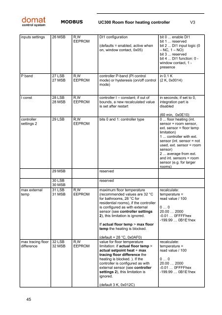
MODBUS UC300 Room floor heating controller V3 inputs settings 26 MSB R,W EEPROM DI1 configuration (defaults = enabled, active when on, window contact, 0x05) bit 0 ... enable DI1 bit 1 ... reserved bit 2 ... DI1 input logic (0 – NC, 1 – NO) bit 3 ... reserved bit 4 ... DI1 function: 0 - window contact, 1 - presence P band 27 LSB 27 MSB R,W EEPROM controller P-band (PI control mode) or hysteresis (on/off control mode) in 0.1 K (2 K, 0x0014) I const 28 LSB 28 MSB R,W EEPROM controller I – constant; if out of bounds, a new recalculated value is set after restart in seconds; if set to 0, integration part is disabled controller settings 2 29 LSB R,W EEPROM 29 MSB reserved bits 0 and 1: controller type (60 min, 0x0E10) 0 ... floor heating (int. sensor = room sensor, ext. sensor = floor temp limitation) 1 ... controller with ext. sensor (int. sensor = not used, ext. sensor = room sensor) 2 ... average from ext. and int. sensors = room sensor (e.g. for larger rooms) max external temp 30 LSB 30 MSB 31 LSB 31 MSB R,W EEPROM reserved maximum floor temperature (recommended values are 32 °C for bathrooms, 28 °C for residential rooms), if the controller is configured as with external sensor (see controller settings 2), this limitation is ignored. If actual floor temp > max floor temp the heating is blocked. recalculate: temperature = read value / 100 0 … 0 20.00 … 2000 -0.01 … 0FFFFhex -199.99 … 0B1E1hex max tracing floor difference 32 LSB 32 MSB R,W EEPROM (default = 28 °C, 0x0AF0) value for floor temperature limitation: if actual floor temp > actual setpoint heat + max tracing floor difference the heating is blocked. ). If the controller is configured as with external sensor (see controller settings 2), this limitation is ignored. recalculate: temperature = read value / 100 0 … 0 20.00 … 2000 -0.01 … 0FFFFhex -199.99 … 0B1E1hex (default 3 K, 0x012C) 45
- Page 1 and 2: Room units and controllers Communic
- Page 3 and 4: MODBUS General V3 General • All r
- Page 5 and 6: MODBUS UI01x User interface V3 stat
- Page 7 and 8: MODBUS UI01x User interface V3 set
- Page 9 and 10: MODBUS UI01x User interface V3 sett
- Page 11 and 12: MODBUS UI01x User interface V3 max
- Page 13 and 14: MODBUS UI01x User interface V3 dec
- Page 15 and 16: MODBUS UI01x User interface V3 allo
- Page 17 and 18: MODBUS UI01x User interface V3 disp
- Page 19 and 20: MODBUS UI01x User interface V3 prog
- Page 21 and 22: MODBUS UI01x User interface V3 actu
- Page 23 and 24: MODBUS UC100 Room controller V3 UC1
- Page 25 and 26: MODBUS UC100 Room controller V3 set
- Page 27 and 28: MODBUS UC100 Room controller V3 P b
- Page 29 and 30: MODBUS UC100 Room controller V3 pre
- Page 31 and 32: MODBUS UC100 Room controller V3 Rea
- Page 33 and 34: MODBUS UC200 Room controller V3 5 M
- Page 35 and 36: MODBUS UC200 Room controller V3 act
- Page 37 and 38: MODBUS UC200 Room controller V3 max
- Page 39 and 40: MODBUS UC200 Room controller V3 pro
- Page 41 and 42: MODBUS UC300 Room floor heating con
- Page 43: MODBUS UC300 Room floor heating con
- Page 47 and 48: MODBUS UC300 Room floor heating con
- Page 49 and 50: MODBUS UC300 Room floor heating con
- Page 51 and 52: MODBUS FC010 Fancoil controller V3
- Page 53 and 54: MODBUS FC010 Fancoil controller V3
- Page 55 and 56: MODBUS FC010 Fancoil controller V3
- Page 57 and 58: MODBUS FC010 Fancoil controller V3
- Page 59 and 60: MODBUS FC010 Fancoil controller V3
- Page 61 and 62: MODBUS FC020 Fancoil controller V2
- Page 63 and 64: MODBUS FC020 Fancoil controller V2
- Page 65 and 66: MODBUS FC020 Fancoil controller V2
- Page 67 and 68: MODBUS FC020 Fancoil controller V2
- Page 69 and 70: MODBUS FC020 Fancoil controller V2
- Page 71 and 72: MODBUS UC210 Dynamic radiator contr
- Page 73 and 74: MODBUS UC210 Dynamic radiator contr
- Page 75 and 76: MODBUS UC210 Dynamic radiator contr
- Page 77 and 78: MODBUS UC210 Dynamic radiator contr
- Page 79 and 80: MODBUS UC220 Dynamic room controlle
- Page 81 and 82: MODBUS UC220 Dynamic room controlle
- Page 83 and 84: MODBUS UC220 Dynamic room controlle
- Page 85 and 86: MODBUS UC220 Dynamic room controlle
- Page 87 and 88: MODBUS UC220 Dynamic room controlle
- Page 89 and 90: MODBUS US100 Heating controller wit
- Page 91 and 92: MODBUS US100 Heating controller wit
- Page 93 and 94: MODBUS US100 Heating controller wit
MODBUS UC300 <strong>Room</strong> floor heating controller V3<br />
inputs settings 26 MSB R,W<br />
EEPROM<br />
DI1 configuration<br />
(defaults = enabled, active when<br />
on, window contact, 0x05)<br />
bit 0 ... enable DI1<br />
bit 1 ... reserved<br />
bit 2 ... DI1 input logic (0<br />
– NC, 1 – NO)<br />
bit 3 ... reserved<br />
bit 4 ... DI1 function: 0 -<br />
window contact, 1 -<br />
presence<br />
P b<strong>and</strong><br />
27 LSB<br />
27 MSB<br />
R,W<br />
EEPROM<br />
controller P-b<strong>and</strong> (PI control<br />
mode) or hysteresis (on/off control<br />
mode)<br />
in 0.1 K<br />
(2 K, 0x0014)<br />
I const<br />
28 LSB<br />
28 MSB<br />
R,W<br />
EEPROM<br />
controller I – constant; if out of<br />
bounds, a new recalculated value<br />
is set after restart<br />
in seconds; if set to 0,<br />
integration part is<br />
disabled<br />
controller<br />
settings 2<br />
29 LSB R,W<br />
EEPROM<br />
29 MSB reserved<br />
bits 0 <strong>and</strong> 1: controller type<br />
(60 min, 0x0E10)<br />
0 ... floor heating (int.<br />
sensor = room sensor,<br />
ext. sensor = floor temp<br />
limitation)<br />
1 ... controller with ext.<br />
sensor (int. sensor = not<br />
used, ext. sensor = room<br />
sensor)<br />
2 ... average from ext.<br />
<strong>and</strong> int. sensors = room<br />
sensor (e.g. for larger<br />
rooms)<br />
max external<br />
temp<br />
30 LSB<br />
30 MSB<br />
31 LSB<br />
31 MSB<br />
R,W<br />
EEPROM<br />
reserved<br />
maximum floor temperature<br />
(recommended values are 32 °C<br />
for bathrooms, 28 °C for<br />
residential rooms), if the controller<br />
is configured as with external<br />
sensor (see controller settings<br />
2), this limitation is ignored.<br />
If actual floor temp > max floor<br />
temp the heating is blocked.<br />
recalculate:<br />
temperature =<br />
read value / 100<br />
0 … 0<br />
20.00 … 2000<br />
-0.01 … 0FFFFhex<br />
-199.99 … 0B1E1hex<br />
max tracing floor<br />
difference<br />
32 LSB<br />
32 MSB<br />
R,W<br />
EEPROM<br />
(default = 28 °C, 0x0AF0)<br />
value for floor temperature<br />
limitation: if actual floor temp ><br />
actual setpoint heat + max<br />
tracing floor difference the<br />
heating is blocked. ). If the<br />
controller is configured as with<br />
external sensor (see controller<br />
settings 2), this limitation is<br />
ignored.<br />
recalculate:<br />
temperature =<br />
read value / 100<br />
0 … 0<br />
20.00 … 2000<br />
-0.01 … 0FFFFhex<br />
-199.99 … 0B1E1hex<br />
(default 3 K, 0x012C)<br />
45


