Room units and controllers - Domat International
Room units and controllers - Domat International
Room units and controllers - Domat International

Create successful ePaper yourself
Turn your PDF publications into a flip-book with our unique Google optimized e-Paper software.
<strong>Room</strong> <strong>units</strong> <strong>and</strong> <strong>controllers</strong><br />
Communication protocol description<br />
Document version 06/2010
MODBUS General V3<br />
Contents<br />
General .......................................................................................................................... 3<br />
UIxxx – room unit, UXxxx - room unit with blinds control ............................................... 4<br />
UC100 – room controller, knob + RTC ..........................................................................23<br />
UC200 – room controller, heating <strong>and</strong> cooling, knob + RTC..........................................32<br />
UC300 – room floor heating controller, knob + RTC, ext. Pt1000 floor sensor...............41<br />
FC010 – fancoil controller (with UC010), RTC, 5x DO, 2x DI.........................................51<br />
FC020 – fancoil controller, RTC, 4xAI, 2xAO, 7xDO, 4xDI ............................................61<br />
UC210 – room controller, heating <strong>and</strong> Jaga radiator, knob + RTC ................................70<br />
UC220 – room controller, heating, cooling, <strong>and</strong> Jaga radiator, knob + RTC ..................79<br />
US100 – room <strong>and</strong> blinds controller, 5 buttons + RTC, 3xDO, 1xDI...............................88<br />
2
MODBUS General V3<br />
General<br />
• All room <strong>units</strong> <strong>and</strong> <strong>controllers</strong> support Modbus RTU, default is 9600 bps, No parity, 8<br />
bits, 1 stopbit.<br />
• Units are slaves (servers); each unit has a slave address (1 to 250) <strong>and</strong> responds to<br />
the requests from a master (client). Default Modbus slave address is 1.<br />
• The address space can be accessed bitwise or wordwise (i.e. it is possible to read<br />
out eg. from register 0005h the complete word or individual bits). The bits (functions<br />
01, <strong>and</strong> 15) are addressed from the beginning, thus bit 0 at register 0 is read 0000, bit<br />
0 at address 0001 is read at address 0010h, which is 16dec).<br />
• Some registers are read-only, some are read/write to RAM, <strong>and</strong> several values are<br />
written to EEPROM. Please note that the EEPROM write process may be protected<br />
against frequent overwriting by an enable bit (eg. at FC010, register 24, Set fan<br />
mode). This bit is always read as 0.<br />
• Supportes Modbus functions are:<br />
• 01 Read Coil Status –read bits<br />
• 03 Read Holding Registers – read words<br />
• 15 Force Multiple Coils – write bits<br />
• 16 Force Multiple Registers – write words.<br />
NB. Usually, Modbus clients use shifted numbering, <strong>and</strong> 1 must be added to the register<br />
number. Therefore clients with port monitor functionality are strongly recommended for<br />
testing.<br />
Example for UI010:<br />
Request (to UI010)<br />
01 slave address<br />
03 Modbus function 03 - Read multiple registers<br />
00 10 starting address - 16 dec to read register 17, room temp.<br />
00 01 number of registers to read<br />
85 CF CRC<br />
Response (from UI010)<br />
01 slave address<br />
03 Modbus function 03 - Read multiple registers<br />
02 number of bytes to follow<br />
07 9E value: 1950 dec = 19.5 °C<br />
3B DC CRC<br />
To check communication <strong>and</strong> set up the <strong>units</strong>, use domat.exe, a free utility for addressing,<br />
communication tests etc. Its Address editor function may be very useful when debugging.<br />
Available for download at www.rcware.eu.<br />
3
MODBUS UI01x User interface V3<br />
UIxxx – room unit, UXxxx - room unit with blinds control<br />
- 50 words can be read at the same time (i.e. 100 bytes)<br />
- whole range can be addressed bitwise<br />
- not all <strong>units</strong> support all functions (eg. humidity) – refer to the respective data sheets<br />
This table only applies for the new LCD display version – firmware version >100! Contact<br />
technical support for the old display (firmware version 0601hex<br />
UI 512 -> 0602hex<br />
UI 520 -> 0620hex<br />
UI 541 -> 0641hex<br />
UI 542 -> 0642hex<br />
UI 545 -> 0645hex<br />
UI 551 -> 0651hex<br />
UI 552 -> 0652hex<br />
UI 555 -> 0655hex<br />
UI 561 -> 0661hex<br />
UI 562 -> 0662hex<br />
UI 565 -> 0665hex<br />
UI 571 -> 0671hex<br />
UI 572 -> 0672hex<br />
UI 575 -> 0675hex<br />
UI 581 -> 0681hex<br />
UI 582 -> 0682hex<br />
UI 585 -> 0685hex<br />
UI6xx:<br />
UI 611 -> 0701hex<br />
UI 612 -> 0702hex<br />
UI 620 -> 0720hex<br />
UI 641 -> 0741hex<br />
UI 642 -> 0742hex<br />
UI 645 -> 0745hex<br />
UI 651 -> 0751hex<br />
UI 652 -> 0752hex<br />
UI 655 -> 0755hex<br />
UI 661 -> 0761hex<br />
UI 662 -> 0762hex<br />
UI 665 -> 0765hex<br />
UI 671 -> 0771hex<br />
UI 672 -> 0772hex<br />
UI 675 -> 0775hex<br />
UI 681 -> 0781hex<br />
UI 682 -> 0782hex<br />
UI 685 -> 0785hex<br />
UI 010 -> 0200hex<br />
UI 011 -> 0201hex<br />
UI 012 -> 0202hex<br />
UI 020 -> 0220hex<br />
UI 041 -> 0241hex<br />
UI 042 -> 0242hex<br />
UI 045 -> 0245hex<br />
UI 051 -> 0251hex<br />
UI 052 -> 0252hex<br />
UI 055 -> 0255hex<br />
UI 061 -> 0261hex<br />
UI 062 -> 0262hex<br />
UI 065 -> 0265hex<br />
UI 071 -> 0271hex<br />
UI 072 -> 0272hex<br />
UI 075 -> 0275hex<br />
UI 081 -> 0281hex<br />
UI 082 -> 0282hex<br />
UI 085 -> 0285hex<br />
UX0xx:<br />
UX 011 -> 1201hex<br />
UX 015 -> 1220hex<br />
UX 041 -> 1241hex<br />
UX 045 -> 1245hex<br />
firmware<br />
4<br />
2 LSB<br />
2 MSB<br />
R firmware version >100 dec for new displays
MODBUS UI01x User interface V3<br />
status LSB 3 LSB R, W RAM module status lower byte<br />
bit 0 – write to EEPROM enabled<br />
bit 4 – init EEPROM<br />
bit 5 – central write block (all RW<br />
registers)<br />
status MSB 3 MSB R module status upper byte<br />
bit 0 0 normal mode<br />
1 init mode<br />
bit 1<br />
Registers 4...6 for UX... <strong>and</strong> UI0... (RS485)<br />
1 at the next EEPROM write<br />
attempt will all data be<br />
written to EEPROM<br />
0 at the next EEPROM write<br />
attempt will all data be<br />
written to RAM only<br />
bit 2 – 1 – EEPROM initialized<br />
bit 3 – central write block indication<br />
bit 4 – edit state indication<br />
bit 5 - 1<br />
bit 6 - 0<br />
bit 7 – 1<br />
Init EEPROM follows if the<br />
INIT switch was ON at<br />
power up, <strong>and</strong> if INIT<br />
switch was OFF at setting<br />
bit 4 to 1 (indicated by bit<br />
2 in Status MSB)<br />
bit 3 – is set by setting of<br />
bit 5 in reg. 3 (status LSB)<br />
bit 4 – indication of editing<br />
mode: 1 while user<br />
operates the knob, all<br />
write atempts over the bus<br />
are ignored (the same<br />
function as central write<br />
block)<br />
address 4 LSB R,W<br />
EEPROM<br />
baud rate 4 MSB R,W<br />
EEPROM<br />
serial port<br />
settings<br />
5 LSB R,W<br />
EEPROM<br />
Modbus module address<br />
(default = 1)<br />
10dec … 1 200 bps<br />
11dec … 2 400 bps<br />
12dec … 4 800 bps<br />
13dec … 9 600 bps (default)<br />
14dec … 19 200 bps<br />
15dec … 38 400 bps<br />
16dec … 57 600 bps<br />
17dec … 115 200 bps<br />
serial port communication<br />
parameters<br />
(default = no parity, one stop bit:<br />
0x00)<br />
!!! the change will be<br />
effective after restart only<br />
(however the register will<br />
be set immediately)<br />
!!! the change will be<br />
effective after restart only<br />
(however the register will<br />
be set immediately)<br />
bit 0-1 ... parity<br />
(00 – no parity, 01 – even,<br />
10 – odd)<br />
bit 2 ... stop bits (0 – one,<br />
1 - two)<br />
5 MSB reserved<br />
!!! the change will be<br />
effective after restart only<br />
(however the register will<br />
be set immediately)<br />
6 LSB<br />
reserved<br />
6 MSB<br />
Registers 4...6 for UI5... <strong>and</strong> UI6... (Ethernet)<br />
uptime<br />
firmware 2<br />
4 LSB<br />
4 MSB<br />
5 LSB<br />
5 MSB<br />
6 LSB<br />
R<br />
R<br />
uptime (s)<br />
Ethernet processor firmware<br />
version<br />
6 MSB<br />
relay 7 LSB R, W RAM comm<strong>and</strong>s to set the digital outputs<br />
(DO1, DO2)<br />
bit 0 ... DO 1<br />
bit 1 ... DO 2<br />
5
MODBUS UI01x User interface V3<br />
latch enable 7 MSB R, W RAM after setting to 1, the latched value<br />
(register 10 MSB) for a particular bit<br />
changes to 0 <strong>and</strong> stays so until a<br />
new value is registered at the input;<br />
after power reset the complete<br />
register is set to 0<br />
time<br />
programme<br />
output<br />
password<br />
8 LSB<br />
8 MSB<br />
9 LSB<br />
9 MSB<br />
R<br />
R,W,<br />
EEPROM<br />
time scheduler output (the output<br />
value depends on the time schedule<br />
type, see the settings register<br />
password to access the protected<br />
items (e.g. party mode) –<br />
customized function<br />
inputs 10 LSB R readout of digital inputs (DI1, DI2,<br />
PUSH)<br />
latched values 10 MSB R catched values<br />
0 – since latch enable there was no<br />
change on the bit<br />
1 - since latch enable the bit value<br />
has changed its state<br />
set temp<br />
11 LSB<br />
11 MSB<br />
R,W<br />
EEPROM<br />
temperature set by user<br />
e.g. 21.5°C reads 2150<br />
(UX... read-only, blinds up)<br />
bit 2 ... DO 3<br />
(only for UX..., read-only,<br />
blinds down)<br />
to reset the individual set<br />
bits in the latched value<br />
register, set the particular<br />
bit to 1 (= disable <strong>and</strong><br />
enable latch)<br />
1) multistate scheduler:<br />
0x01, 0x02, 0x04<br />
(presence / day/night<br />
mode)<br />
2) analogue scheduler:<br />
directly the value<br />
saved in the time<br />
schedule registers<br />
default = 0x0000<br />
bit 0 ... DI 1<br />
bit 1 ... DI 2<br />
bit 2 ... PUSH button<br />
bit 0 ... DI 1<br />
bit 1 ... DI 2<br />
bit 2 ... PUSH button; to<br />
reset the bits, disable <strong>and</strong><br />
enable latch - see latch<br />
enable<br />
recalculate:<br />
set temperature =<br />
read value / 100<br />
set day<br />
/comfort temp<br />
set night /<br />
precomfort<br />
temp<br />
12 LSB<br />
12 MSB<br />
13 LSB<br />
13 MSB<br />
R,W<br />
EEPROM<br />
R,W<br />
EEPROM<br />
(default = 23 °C)<br />
day mode temperature setpoint<br />
set by user (when editing, the<br />
symbols thermometer <strong>and</strong> sun are<br />
active)<br />
(default = 23 °C)<br />
night mode temperature setpoint<br />
set by user (when editing, the<br />
symbols thermometer <strong>and</strong> moon<br />
are active)<br />
(default = 18 °C)<br />
0 … 0<br />
199.99 … 19999<br />
-0.01 … 0FFFFhex<br />
-199.99 … 0B1E1hex<br />
recalculate:<br />
set temperature =<br />
read value / 100<br />
0 … 0<br />
199.99 … 19999<br />
-0.01 … 0FFFFhex<br />
-199.99 … 0B1E1hex<br />
recalculate:<br />
set temperature =<br />
read value / 100<br />
0 … 0<br />
199.99 … 19999<br />
-0.01 … 0FFFFhex<br />
-199.99 … 0B1E1hex<br />
6
MODBUS UI01x User interface V3<br />
set outside<br />
/depression<br />
temp<br />
set DHW<br />
temp<br />
set heating<br />
curve<br />
14 LSB<br />
14 MSB<br />
15 LSB<br />
15 MSB<br />
R,W<br />
EEPROM<br />
R,W<br />
EEPROM<br />
16 LSB R,W<br />
EEPROM<br />
set outside temperature (at which<br />
heating may be enabled), step <strong>and</strong><br />
resolution is fixed to 1 °C (when<br />
editing, the symbols thermometer<br />
<strong>and</strong> house are active)<br />
(default = 15 °C)<br />
DHW setpoint temperature, step<br />
<strong>and</strong> resolution is fixed to 1 °C (when<br />
editing, the symbols thermometer<br />
<strong>and</strong> water tap are active)<br />
(default = 50 °C)<br />
heating curve type set by user<br />
(when editing, the symbols heating<br />
<strong>and</strong> boiler are active)<br />
recalculate:<br />
set temperature =<br />
read value / 100<br />
0 … 0<br />
199.99 … 19999<br />
-0.01 … 0FFFFhex<br />
-199.99 … 0B1E1hex<br />
recalculate:<br />
set temperature =<br />
read value / 100<br />
0 … 0<br />
199.99 … 19999<br />
-0.01 … 0FFFFhex<br />
-199.99 … 0B1E1hex<br />
set value = 1 .. 4<br />
(default = 1)<br />
16 MSB reserved<br />
actual temp<br />
17 LSB<br />
17 MSB<br />
R<br />
actual temperature measured by<br />
the internal sensor incl. correction<br />
(see corr temp)<br />
recalculate:<br />
temperature<br />
= read value / 100<br />
0 … 0<br />
199.99 … 19999<br />
-0.01 … 0FFFFhex<br />
-199.99 … 0B1E1hex<br />
set rh<br />
18 LSB<br />
18 MSB<br />
R,W<br />
EEPROM<br />
relative humidity set by user<br />
(default = 40 %, 0x0FA0)<br />
recalculate:<br />
humidity<br />
= read value / 100<br />
actual rh<br />
set presence<br />
mode<br />
19 LSB<br />
19 MSB<br />
R<br />
20 LSB R,W<br />
EEPROM<br />
actual relative humidity measured<br />
by the internal sensor, incl.<br />
correction (see corr rh sensor)<br />
(only for types containing humidity<br />
sensor)<br />
presence mode set by user<br />
(for hotels)<br />
The register is to be set by 16 bit<br />
writing comm<strong>and</strong>.<br />
(default = 0x00)<br />
0 … 0<br />
100.00 … 10000<br />
recalculate:<br />
humidity<br />
= read value / 100<br />
0 … 0<br />
100.00 … 10000<br />
bit 0 … comfort (occupied<br />
house)<br />
bit 1 … st<strong>and</strong>by (empty<br />
house)<br />
bit 2 … off (Off)<br />
bit 3 … party (occupied<br />
house + drink)<br />
bit 4 ... auto (clock), time<br />
schedule (if enabled)<br />
bit 5 ... holiday (clock +<br />
empty house)<br />
bit 6 ... reserved<br />
bit 7 ... disable writing<br />
(0 – value will be written to<br />
EEPROM, 1 – writing<br />
disabled.)<br />
7
MODBUS UI01x User interface V3<br />
set day/night<br />
mode<br />
20 MSB R,W<br />
EEPROM<br />
set fan mode 21 LSB R,W<br />
EEPROM<br />
set heat/cool<br />
mode<br />
21 MSB R,W<br />
EEPROM<br />
day/night mode set by user<br />
(for residential applications)<br />
The register is to be set by 16 bit<br />
writing comm<strong>and</strong>.<br />
(default = 0x00)<br />
fan mode set by user<br />
(for fancoils, convectors, AHUs)<br />
The register is to be set by 16 bit<br />
writing comm<strong>and</strong>.<br />
(default = 0x00)<br />
heat/cool mode set by user<br />
(for split <strong>units</strong>, heat pumps etc.)<br />
The disable writing bit may be<br />
used to write selectively (only when<br />
the presence mode value changes)<br />
as EEPROM is not suitable for<br />
permanent writing. This bit is not<br />
written to the register.<br />
bit 0 … day auto (clock,<br />
sun)<br />
bit 1 … night auto (clock,<br />
moon)<br />
bit 2 … day manual (sun)<br />
bit 3 … night manual<br />
(moon)<br />
bit 4 ... off (Off)<br />
bit 5 ... auto (clock), time<br />
schedule (if enabled)<br />
bit 6 ... holiday (clock +<br />
house)<br />
bit 7 ... disable writing<br />
(0 – value will be written to<br />
EEPROM, 1 – writing<br />
disabled.)<br />
bit 0 … Auto (fan + A)<br />
bit 1 … Man Off (fan + M)<br />
bit 2 … Man 1 (fan + M +<br />
Stage 1)<br />
bit 3 … Man 2 (fan + M +<br />
Stage 1,2)<br />
bit 4 ... Man 3 (fan + M +<br />
Stage 1,2,3)<br />
bit 7 ... disable writing<br />
(0 – value will be written to<br />
EEPROM, 1 – writing<br />
disabled.)<br />
bit 0 … off (Off)<br />
bit 1 … heat only (Heat)<br />
bit 2 … cool only (Cool)<br />
bit 3 … fan only (Fan)<br />
bit 4 ... auto (Heat + Cool)<br />
bit 7 ... disable writing<br />
(0 – value will be written to<br />
EEPROM, 1 – writing<br />
disabled.)<br />
The register is to be set by 16 bit<br />
writing comm<strong>and</strong>.<br />
set user<br />
pattern mode<br />
write protect<br />
delay<br />
22 LSB R,W<br />
EEPROM<br />
22 MSB R, W,<br />
EEPROM<br />
state of user defined mode (for<br />
each mode, the complete symbol<br />
set may be redefined) – see user<br />
pattern x symbols x, writing must<br />
follow by a 16-bit comm<strong>and</strong><br />
write protect time in seconds after<br />
user knob operation (default = 10 s,<br />
0x0A)<br />
bit 0 ... user_1_pattern<br />
bit 1 ... user_2_pattern<br />
bit 2 ... user_3_pattern<br />
bit 3 ... user_4_pattern<br />
bit 4 ... user_5_pattern<br />
bit 5...6 – reserved<br />
bit 7 ... disable writing<br />
(0 – value will be written to<br />
EEPROM, 1 – writing<br />
disabled.)<br />
0 = off<br />
(This protection time prevents the<br />
PLC from overriding the values set<br />
manually by the knob.)<br />
8
MODBUS UI01x User interface V3<br />
settings<br />
23 LSB<br />
23 MSB<br />
R,W<br />
EEPROM<br />
latch state 24 LSB R,W<br />
EEPROM<br />
relay comm 24 MSB R,W<br />
EEPROM<br />
relay commfail<br />
state<br />
25 LSB R,W<br />
EEPROM<br />
comm timeout 25 MSB R,W<br />
EEPROM<br />
output power<br />
up enable<br />
26 LSB R,W<br />
EEPROM<br />
output start 26 MSB R,W<br />
EEPROM<br />
min temp<br />
27 LSB<br />
27 MSB<br />
R,W<br />
EEPROM<br />
Modbus frame part receiving: end of<br />
frame is given either by the timeout<br />
since last character (see mb<br />
timeout), i.e. only part of the frame<br />
may be received, or the complete<br />
received frame (checked during<br />
receiving).<br />
knob steps: number of steps to<br />
invoke value change by the defined<br />
step<br />
(default: °C, part receiving off,<br />
password protection off, presence<br />
time programme, 2 steps, 1 step =<br />
0x1200h)<br />
state to be catched<br />
0 – log. 0 (default)<br />
1 – log. 1<br />
0 – no state change on<br />
communication failure (default)<br />
1 – on communication failure (see<br />
comm timeout) the output value<br />
will be set to relay commfail state<br />
(default = 0)<br />
on commfail timeout <strong>and</strong> relay<br />
comm set to 1 the outputs are set<br />
to relay commfail state<br />
(default = 0)<br />
time [secs] of non-communication<br />
which is recognized as<br />
communication failure (default = 0).<br />
On comfail, outputs go to<br />
predefined states (see relay<br />
comm) <strong>and</strong> alarm bell symbol is<br />
activated on the display.<br />
startup function enable<br />
0 – no setting of outputs after power<br />
up until first communication<br />
1 – the outputs go to the output<br />
start values after power up until the<br />
first outputs comm<strong>and</strong> is received<br />
(default = 0)<br />
output status at power up, only<br />
active if output power up enable<br />
(default = 0)<br />
minimum temperature which user<br />
can set as setpoint for temp, day<br />
<strong>and</strong> night<br />
-199.99 to 199.99<br />
(default = 18°C, 0x0708)<br />
bit 0 ... (0 – temperature<br />
display in °C, 1 – in °F;<br />
applies to LCD display<br />
only, communication is<br />
always in °C)<br />
bit 1... Modbus frame part<br />
receiving (change applies<br />
after restart) – 0: off, 1: on<br />
bit 2-3 ... time schedule<br />
type (0: presence/daynight,<br />
1: on/off, 2:<br />
analogue)<br />
bit 4 ... party mode<br />
protected by password<br />
bit 5-7 ... reserved<br />
bit 8-11 ... knob steps in<br />
short edit mode<br />
bit 12-15 ... knob steps in<br />
long edit mode<br />
bit 0 ... DI 1<br />
bit 1 ... DI 2<br />
bit 2 ... PUSH button (fixed<br />
to 1 – push of the button)<br />
bit 0 ... DO 1<br />
bit 1 ... DO 2<br />
bit 0 ... DO 1<br />
bit 1 ... DO 2<br />
if the value is set to 0, no<br />
comm fail function is<br />
implemented<br />
bit 0 ... DO 1<br />
bit 1 ... DO 2<br />
May be used for<br />
commissioning.<br />
bit 0 ... DO 1<br />
bit 1 ... DO 2<br />
recalculate:<br />
temperature<br />
= read value / 100<br />
0 … 0<br />
199.99 … 19999<br />
-0.01 … 0FFFFhex<br />
-199.99 … 0B1E1hex<br />
9
MODBUS UI01x User interface V3<br />
max temp<br />
min outside<br />
temp<br />
max outside<br />
temp<br />
min DHW<br />
temp<br />
28 MSB<br />
28 MSB<br />
29 LSB<br />
29 MSB<br />
30 MSB<br />
30 MSB<br />
31 LSB<br />
31 MSB<br />
R,W<br />
EEPROM<br />
R,W<br />
EEPROM<br />
R,W<br />
EEPROM<br />
R,W<br />
EEPROM<br />
maximum temperature which user<br />
can set as setpoint for temp, day<br />
<strong>and</strong> night<br />
-199.99 to 199.99<br />
(default = 26°C, 0x0A28)<br />
minimum outside temperature<br />
which user can set as setpoint for<br />
heating enable<br />
-199.99 to 199.99<br />
(default = -20°C, 0xF830)<br />
maximum outside temperature<br />
which user can set as setpoint for<br />
heating enable<br />
-199.99 to 199.99<br />
(default = 30°C, 0x0BB8)<br />
minimum temperature which user<br />
can set as setpoint for DHW<br />
-199.99 to 199.99<br />
recalculate:<br />
temperature<br />
= read value / 100<br />
0 … 0<br />
199.99 … 19999<br />
-0.01 … 0FFFFhex<br />
-199.99 … 0B1E1hex<br />
recalculate:<br />
temperature<br />
= read value / 100<br />
0 … 0<br />
199.99 … 19999<br />
-0.01 … 0FFFFhex<br />
-199.99 … 0B1E1hex<br />
recalculate:<br />
temperature<br />
= read value / 100<br />
0 … 0<br />
199.99 … 19999<br />
-0.01 … 0FFFFhex<br />
-199.99 … 0B1E1hex<br />
recalculate:<br />
temperature<br />
= read value / 100<br />
max DHW<br />
temp<br />
32 MSB<br />
32 MSB<br />
R,W<br />
EEPROM<br />
(default = 10°C, 0x03E8)<br />
maximum temperature which user<br />
can set as setpoint for DHW<br />
-199.99 to 199.99<br />
0 … 0<br />
199.99 … 19999<br />
-0.01 … 0FFFFhex<br />
-199.99 … 0B1E1hex<br />
recalculate:<br />
temperature<br />
= read value / 100<br />
corr temp<br />
min rh<br />
33 MSB<br />
33 MSB<br />
34 LSB<br />
34 MSB<br />
R,W<br />
EEPROM<br />
R,W<br />
EEPROM<br />
(default = 90°C, 0x2328)<br />
correction: adds to the actual<br />
temperature measured by the<br />
internal sensor; compensates the<br />
internal thermal loss<br />
-20.00 to 20.00<br />
(default = about -1.5°C, depending<br />
on module type)<br />
minimum humidity which user can<br />
set as setpoint<br />
0.00% to 100.00%<br />
(default = 10%, 0x03E8)<br />
0 … 0<br />
199.99 … 19999<br />
-0.01 … 0FFFFhex<br />
-199.99 … 0B1E1hex<br />
recalculate:<br />
temperature<br />
= read value / 100<br />
0 … 0<br />
199.99 … 19999<br />
-0.01 … 0FFFFhex<br />
-199.99 … 0B1E1hex<br />
recalculate:<br />
humidity<br />
= read value / 100<br />
0 … 0<br />
100.00 … 10000<br />
10
MODBUS UI01x User interface V3<br />
max rh<br />
corr rh<br />
min remote 0<br />
max remote 0<br />
min remote 1<br />
max remote 1<br />
min remote 2<br />
35 LSB<br />
35 MSB<br />
36 LSB<br />
36 MSB<br />
37 LSB<br />
37 MSB<br />
38 LSB<br />
38 MSB<br />
39 LSB<br />
39 MSB<br />
40 LSB<br />
40 MSB<br />
41 LSB<br />
41 MSB<br />
R,W<br />
EEPROM<br />
R,W<br />
EEPROM<br />
R,W<br />
EEPROM<br />
R,W<br />
EEPROM<br />
R,W<br />
EEPROM<br />
R,W<br />
EEPROM<br />
R,W<br />
EEPROM<br />
maximum humidity which user can<br />
set as setpoint<br />
0.00% to 100.00%<br />
(default = 90%, 0x2328)<br />
correction: adds to the actual<br />
humidity measured by the internal<br />
sensor (applicable for types with<br />
humidity sensor only)<br />
-10.00 to 10.00 %<br />
(default = 0)<br />
minimum value which user can set<br />
as remote 0<br />
-199.99 to 199.99<br />
(default = -199.99)<br />
maximum value which user can set<br />
as remote 0<br />
-199.99 to 199.99<br />
(default = 199.99)<br />
minimum value which user can set<br />
as remote 1<br />
-199.99 to 199.99<br />
(default = -199.99)<br />
maximum value which user can set<br />
as remote 1<br />
-199.99 to 199.99<br />
(default = 199.99)<br />
minimum value which user can set<br />
as remote 2<br />
-199.99 to 199.99<br />
(default = -199.99)<br />
recalculate:<br />
humidity<br />
= read value / 100<br />
0 … 0<br />
100.00 … 10000<br />
recalculate:<br />
humidity<br />
= read value / 100<br />
0 … 0<br />
199.99 … 19999<br />
-0.01 … 0FFFFhex<br />
-199.99 … 0B1E1hex<br />
recalculate:<br />
remote value<br />
= read value / 100<br />
0 … 0<br />
199.99 … 19999<br />
-0.01 … 0FFFFhex<br />
-199.99 … 0B1E1hex<br />
recalculate:<br />
remote value<br />
= read value / 100<br />
0 … 0<br />
199.99 … 19999<br />
-0.01 … 0FFFFhex<br />
-199.99 … 0B1E1hex<br />
recalculate:<br />
remote value<br />
= read value / 100<br />
0 … 0<br />
199.99 … 19999<br />
-0.01 … 0FFFFhex<br />
-199.99 … 0B1E1hex<br />
recalculate:<br />
remote value<br />
= read value / 100<br />
0 … 0<br />
199.99 … 19999<br />
-0.01 … 0FFFFhex<br />
-199.99 … 0B1E1hex<br />
recalculate:<br />
remote value<br />
= read value / 100<br />
0 … 0<br />
199.99 … 19999<br />
-0.01 … 0FFFFhex<br />
-199.99 … 0B1E1hex<br />
11
MODBUS UI01x User interface V3<br />
max remote 2<br />
min remote 3<br />
max remote 3<br />
min remote 4<br />
max remote 4<br />
min analogue<br />
time<br />
programme<br />
value<br />
max analogue<br />
time<br />
programme<br />
value<br />
dec places 1<br />
42 LSB<br />
42 MSB<br />
43 LSB<br />
43 MSB<br />
44 LSB<br />
44 MSB<br />
45 LSB<br />
45 MSB<br />
46 LSB<br />
46 MSB<br />
47 LSB<br />
47 MSB<br />
48 LSB<br />
48 MSB<br />
49 LSB<br />
49 MSB<br />
R,W<br />
EEPROM<br />
R,W<br />
EEPROM<br />
R,W<br />
EEPROM<br />
R,W<br />
EEPROM<br />
R,W<br />
EEPROM<br />
R,W<br />
EEPROM<br />
R,W<br />
EEPROM<br />
R,W<br />
EEPROM<br />
maximum value which user can set<br />
as remote 2<br />
-199.99 to 199.99<br />
(default = 199.99)<br />
minimum value which user can set<br />
as remote 3<br />
-199.99 to 199.99<br />
(default = -199.99)<br />
maximum value which user can set<br />
as remote 3<br />
-199.99 to 199.99<br />
(default = 199.99)<br />
minimum value which user can set<br />
as remote 4<br />
-199.99 to 199.99<br />
(default = -199.99)<br />
maximum value which user can set<br />
as remote 4<br />
-199.99 to 199.99<br />
(default = 199.99)<br />
minimum value which user can set<br />
as analogue time schedule value<br />
0 to 199.99<br />
(default = 5.0)<br />
maximum value which user can set<br />
as analogue time schedule value<br />
0 to 199.99<br />
(default = 36.0)<br />
LSB number of decimals for<br />
temperature display (default = 1)<br />
MSB number of decimals for<br />
temperature setting (default = 1)<br />
recalculate:<br />
remote value<br />
= read value / 100<br />
0 … 0<br />
199.99 … 19999<br />
-0.01 … 0FFFFhex<br />
-199.99 … 0B1E1hex<br />
recalculate:<br />
remote value<br />
= read value / 100<br />
0 … 0<br />
199.99 … 19999<br />
-0.01 … 0FFFFhex<br />
-199.99 … 0B1E1hex<br />
recalculate:<br />
remote value<br />
= read value / 100<br />
0 … 0<br />
199.99 … 19999<br />
-0.01 … 0FFFFhex<br />
-199.99 … 0B1E1hex<br />
recalculate:<br />
remote value<br />
= read value / 100<br />
0 … 0<br />
199.99 … 19999<br />
-0.01 … 0FFFFhex<br />
-199.99 … 0B1E1hex<br />
recalculate:<br />
remote value<br />
= read value / 100<br />
0 … 0<br />
199.99 … 19999<br />
recalculate:<br />
remote value<br />
= read value / 100<br />
0 … 0<br />
199.99 … 19999<br />
recalculate:<br />
remote value<br />
= read value / 100<br />
0 … 0<br />
199.99 … 19999<br />
-0.01 … 0FFFFhex<br />
-199.99 … 0B1E1hex<br />
0 … no (##)<br />
1 … one (##.#)<br />
2 … two (##.##)<br />
12
MODBUS UI01x User interface V3<br />
dec places 2<br />
dec places 3<br />
dec places 4<br />
dec places 5<br />
dec places 6<br />
dec places 7<br />
dec places<br />
analogue time<br />
programme<br />
50 LSB<br />
50 MSB<br />
51 LSB<br />
51 MSB<br />
52 LSB<br />
52 MSB<br />
53 LSB<br />
53 MSB<br />
54 LSB<br />
54 MSB<br />
55 LSB<br />
55 MSB<br />
R,W<br />
EEPROM<br />
R,W<br />
EEPROM<br />
R,W<br />
EEPROM<br />
R,W<br />
EEPROM<br />
R,W<br />
EEPROM<br />
R,W<br />
EEPROM<br />
56 LSB R,W<br />
EEPROM<br />
step minutes 56 MSB R,W<br />
EEPROM<br />
step 1<br />
step 2<br />
step 3<br />
57 LSB<br />
57 MSB<br />
58 LSB<br />
58 MSB<br />
59 LSB<br />
59 MSB<br />
R,W<br />
EEPROM<br />
R,W<br />
EEPROM<br />
R,W<br />
EEPROM<br />
step 4 60 LSB R,W<br />
EEPROM<br />
step time<br />
programme<br />
60 MSB R,W<br />
EEPROM<br />
LSB number of decimals for<br />
humidity display (default = 0)<br />
MSB number of decimals for<br />
humidity setting (default = 0)<br />
LSB number of decimals for<br />
remote 0 display (default = 2)<br />
MSB number of decimals for<br />
remote 0 setting (default = 2)<br />
LSB number of decimals for<br />
remote 1 display (default = 2)<br />
MSB number of decimals for<br />
remote 1 setting (default = 2)<br />
LSB number of decimals for<br />
remote 2 display (default = 2)<br />
MSB number of decimals for<br />
remote 2 setting (default = 2)<br />
LSB number of decimals for<br />
remote 3 display (default = 2)<br />
MSB number of decimals for<br />
remote 3 setting (default = 2)<br />
LSB number of decimals for<br />
remote 4 display (default = 2)<br />
MSB number of decimals for<br />
remote 4 setting (default = 2)<br />
LSB number of decimals for<br />
analogue time schedule display<br />
(default = 1)<br />
step in minutes for setting time with<br />
a knob in time schedules<br />
(default = 5 min, 0x05)<br />
LSB step for temperature settings<br />
(default = 0.5 °C)<br />
MSB step for humidity settings<br />
(default = 1 %)<br />
LSB step for remote 0 settings<br />
(default = 1)<br />
MSB step for remote 1 settings<br />
(default = 1)<br />
LSB step for remote 2 settings<br />
(default = 1)<br />
MSB step for remote 3 settings<br />
(default = 1)<br />
LSB step for remote 4 settings<br />
(default = 1)<br />
MSB step for analogue time<br />
schedule settings (default = 0.5,<br />
0x32)<br />
0 … no (##)<br />
1 … one (##.#)<br />
2 … two (##.##)<br />
0 … no (##)<br />
1 … one (##.#)<br />
2 … two (##.##)<br />
0 … no (##)<br />
1 … one (##.#)<br />
2 … two (##.##)<br />
0 … no (##)<br />
1 … one (##.#)<br />
2 … two (##.##)<br />
0 … no (##)<br />
1 … one (##.#)<br />
2 … two (##.##)<br />
0 … no (##)<br />
1 … one (##.#)<br />
2 … two (##.##)<br />
0 … no (##)<br />
1 … one (##.#)<br />
2 … two (##.##)<br />
step = value / 100<br />
1 … 0.01<br />
2 … 0.02<br />
10 … 0.1 etc.<br />
step = value / 100<br />
1 … 0.01<br />
2 … 0.02<br />
10 … 0.1 etc.<br />
step = value / 100<br />
1 … 0.01<br />
2 … 0.02<br />
10 … 0.1 etc.<br />
step = value / 100<br />
1 … 0.01<br />
2 … 0.02<br />
10 … 0.1 etc.<br />
step = value / 100<br />
1 … 0.01<br />
2 … 0.02<br />
10 … 0.1 etc.<br />
13
MODBUS UI01x User interface V3<br />
mb timeout 61 LSB R,W<br />
EEPROM<br />
mb answer<br />
delay<br />
show mode<br />
14<br />
61 MSB R,W<br />
EEPROM<br />
62 LSB<br />
62 MSB<br />
R,W<br />
EEPROM<br />
show time 63 LSB R,W<br />
EEPROM<br />
edit return<br />
time<br />
quick edit<br />
value<br />
quick edit<br />
mode number<br />
long push<br />
time<br />
63 MSB R,W<br />
EEPROM<br />
64 LSB R,W<br />
EEPROM<br />
64 MSB R,W<br />
EEPROM<br />
65 LSB R,W<br />
EEPROM<br />
time from the last character in the<br />
Modbus frame (in 5 ms) after which<br />
comes a timeout<br />
(range 5...180 ms, default 50 ms =<br />
0x0A)<br />
time to delay the answer to Modbus<br />
master, in 5 ms<br />
(default = 0 ms)<br />
data that roll on the LCD display<br />
(default = temperature, 1)<br />
If only one of the bits is active there<br />
is only one value displayed.<br />
Otherwise they change periodically<br />
after show time.<br />
time (in 100 ms) to display each<br />
value in show mode (default = 2 s,<br />
0x14)<br />
time (in 100 ms) of user inactivity to<br />
return from edit mode to show<br />
mode (default = 10 s, 0x64)<br />
value which is set by turning the<br />
knob. The value must be enabled<br />
for editing at allowed operation<br />
modes.<br />
(default = temperature, 0x00)<br />
number of mode which is editable<br />
through quick edit menu (short push<br />
of the knob). „Change show mode“<br />
changes between displayed values<br />
(see show mode); pushing the<br />
knob displays the first value from<br />
the show mode register.<br />
(default = 0)<br />
time (in 100 ms) evaluated as long<br />
push (go to settings menu / leave<br />
settings menu). Super long push<br />
(time schedule edit) follows 2 secs<br />
after long push. If there is no value<br />
editable in the long push, then time<br />
schedule is edited right away after<br />
long push.<br />
(default = 1.5 s, 0x0F)<br />
see register settings,<br />
frame part receiving<br />
10 = 50 ms<br />
10 = 50 ms<br />
bit 0 … temperature °C/°F<br />
bit 1 … humidity<br />
bit 2 … current time<br />
bit 3 … day temp<br />
bit 4 … night temp<br />
bit 5 … outside temp<br />
bit 6 … DHW temp<br />
bit 7 … heating curve<br />
bit 8 … remote 0<br />
bit 9 … remote 1<br />
bit 10 … remote 2<br />
bit 11 … remote 3<br />
bit 12 … remote 4<br />
bit 13 ... time programme<br />
output<br />
if 0, periodic change<br />
disabled<br />
0 … temperature<br />
1 … humidity<br />
2 … day temp<br />
3 … night temp<br />
4 … outside temp<br />
5 … DHW temp<br />
6 … heating curve<br />
7 … remote 0<br />
8 … remote 1<br />
9 … remote 2<br />
10 … remote 3<br />
11 … remote 4<br />
0 ... no PUSH function<br />
1 ... presence mode<br />
2 ... day/night mode<br />
3 ... fan<br />
4 ... heat/cool mode<br />
5 ... change show mode<br />
6 ... user pattern mode<br />
(see allowed operation<br />
modes)
MODBUS UI01x User interface V3<br />
allowed<br />
operation<br />
modes 2<br />
65 MSB R,W<br />
EEPROM<br />
operation modes that user is able to<br />
set in the settings menu<br />
0 … disabled<br />
1 … enabled<br />
bit 0 … time schedule<br />
bit 1 … time<br />
bit 2 … user pattern mode<br />
bits 3 … 7 - reserved<br />
allowed<br />
operation<br />
modes<br />
presence<br />
mode edit<br />
mask<br />
day/night<br />
mode edit<br />
mask<br />
fan mode edit<br />
mask<br />
heat/cool<br />
mode edit<br />
mask<br />
66 LSB<br />
66 MSB<br />
R,W<br />
EEPROM<br />
67 LSB R,W<br />
EEPROM<br />
67 MSB R,W<br />
EEPROM<br />
68 LSB R,W<br />
EEPROM<br />
68 MSB R,W<br />
EEPROM<br />
(default = 0, none of them)<br />
operation modes that user is able to<br />
set in the settings menu<br />
0 … disabled<br />
1 … enabled<br />
(default = 1, temperature)<br />
states in presence mode that user<br />
is able to switch between<br />
(default = 0, no states)<br />
states in day / night mode that user<br />
is able to switch between<br />
(default = 0, no states)<br />
states in fan mode that user is able<br />
to switch between<br />
(default = 0, no states)<br />
states in heat / cool mode that user<br />
is able to switch between<br />
(default = 0, no states)<br />
bit 0 … temperature<br />
bit 1 … humidity<br />
bit 2 … day temp<br />
bit 3 … night temp<br />
bit 4 … outside temp<br />
bit 5 … DHW temperature<br />
bit 6 … fan<br />
bit 7 … heating curve<br />
bit 8 … presence mode<br />
bit 9 … day/night mode<br />
bit 10 …heat/cool mode<br />
bit 11 … remote 0<br />
bit 12 … remote 1<br />
bit 13 … remote 2<br />
bit 14 … remote 3<br />
bit 15 … remote 4<br />
bit 0 … comfort (occupied<br />
house)<br />
bit 1 … st<strong>and</strong>by (empty<br />
house)<br />
bit 2 … off (Off)<br />
bit 3 … party (occupied<br />
house + drink)<br />
bit 4 … auto (clock)<br />
bit 5 … holiday (clock +<br />
empty house)<br />
bit 0 … day auto (clock +<br />
sun)<br />
bit 1 … night auto (clock +<br />
moon)<br />
bit 2 … day manual (sun)<br />
bit 3 … night manual<br />
(moon)<br />
bit 4 ... off (Off)<br />
bit 5 ... auto (clock)<br />
bit 6 … holiday (clock +<br />
empty house)<br />
bit 0 … Auto (fan + A)<br />
bit 1 … Man Off (fan + M)<br />
bit 2 … Man 1 (fan + M +<br />
Stage 1)<br />
bit 3 … Man 2 (fan + M +<br />
Stage 1,2)<br />
bit 4 ... Man 3 (fan + M +<br />
Stage 1,2,3)<br />
bit 0 … off (Off)<br />
bit 1 … heat only (heat)<br />
bit 2 … cool only (cool)<br />
bit 3 … fan only (fan)<br />
bit 4 ... auto (heat + cool)<br />
15
MODBUS UI01x User interface V3<br />
user pattern<br />
mode edit<br />
mask<br />
69 LSB R,W<br />
EEPROM<br />
69 MSB reserved<br />
states in user pattern mode that<br />
user is able to switch between<br />
(default = 0, no states)<br />
bit 0 ... user_1_pattern<br />
bit 1 ... user_2_pattern<br />
bit 2 ... user_3_pattern<br />
bit 3 ... user_4_pattern<br />
bit 4 ... user_5_pattern<br />
remote/local<br />
symbols 0<br />
70 LSB<br />
70 MSB<br />
71 LSB<br />
71 MSB<br />
R,W RAM<br />
reserved<br />
0 ... symbol controlled locally<br />
1 ... symbol controlled remotely (for<br />
basic values, i.e. all except<br />
remote_x)<br />
Use remote control to set individual<br />
symbols from your PLC.<br />
bit 0 … clock<br />
bit 1 … temp. sensor<br />
bit 2 … house<br />
bit 3 … person<br />
bit 4 … moon<br />
bit 5 … sun<br />
bit 6 … off<br />
bit 7 … drink<br />
bit 8 … heat<br />
bit 9 … cool<br />
bit 10 … water tap (DHW)<br />
bit 11 … spanner (service)<br />
bit 12 … boiler<br />
bit 13 … alarm bell<br />
bit 14 … fan lower<br />
bit 15 … fan upper<br />
remote/local<br />
symbols 1<br />
remote/local<br />
symbols 2<br />
72 LSB<br />
72 MSB<br />
73 LSB<br />
73 MSB<br />
R,W RAM<br />
R,W RAM<br />
0 ... symbol controlled locally<br />
1 ... symbol controlled remotely (for<br />
basic values, i.e. all except<br />
remote_x)<br />
Use remote control to set individual<br />
symbols from your PLC.<br />
0 ... symbol controlled locally<br />
1 ... symbol controlled remotely (for<br />
basic values, i.e. all except<br />
remote_x)<br />
Use remote control to set individual<br />
symbols from your PLC.<br />
bit 0 … °C<br />
bit 1 … °F<br />
bit 2 … %<br />
bit 3 … rH<br />
bit 4 … 1 (weekday)<br />
bit 5 … 2 (weekday)<br />
bit 6 … 3 (weekday)<br />
bit 7 … 4 (weekday)<br />
bit 8 … 5 (weekday)<br />
bit 9 … 6 (weekday)<br />
bit 10 … 7 (weekday)<br />
bit 11 … fan auto<br />
bit 12 … fan manual<br />
bit 13 … fan speed 1<br />
bit 14 … fan speed 2<br />
bit 15 … fan speed 3<br />
bit 0 … SETTING<br />
bit 1 … ERROR<br />
bit 2 … No.<br />
bit 3 … small 7-segment<br />
(upper right corner)<br />
16
MODBUS UI01x User interface V3<br />
display<br />
symbols 0<br />
74 LSB<br />
74 MSB<br />
R,W RAM<br />
displayed symbols for basic values,<br />
i.e. all except remote_x<br />
bit 0 … clock<br />
bit 1 … temp. sensor<br />
bit 2 … house<br />
bit 3 … person<br />
bit 4 … moon<br />
bit 5 … sun<br />
bit 6 … off<br />
bit 7 … drink<br />
bit 8 … heat<br />
bit 9 … cool<br />
bit 10 … water tap (DHW)<br />
bit 11 … spanner (service)<br />
bit 12 … boiler<br />
bit 13 … alarm bell<br />
bit 14 … fan lower<br />
bit 15 … fan upper<br />
display<br />
symbols 1<br />
display<br />
symbols 2<br />
RTC<br />
remote 0<br />
17<br />
75 LSB<br />
75 MSB<br />
76 LSB<br />
76 MSB<br />
77 LSB<br />
77 MSB<br />
78 LSB<br />
78 MSB<br />
79 LSB<br />
79 MSB<br />
80 LSB<br />
80 MSB<br />
81 LSB<br />
81 MSB<br />
R,W RAM<br />
R,W RAM<br />
R,W<br />
EEPROM<br />
displayed symbols for basic values,<br />
i.e. all except remote_x<br />
displayed symbols for basic values,<br />
i.e. all except remote_x<br />
Real time clock (only implemented<br />
in selected types) in BCD coding<br />
bit 0 … °C<br />
bit 1 … °F<br />
bit 2 … %<br />
bit 3 … rH<br />
bit 4 … 1 (weekday)<br />
bit 5 … 2 (weekday)<br />
bit 6 … 3 (weekday)<br />
bit 7 … 4 (weekday)<br />
bit 8 … 5 (weekday)<br />
bit 9 … 6 (weekday)<br />
bit 10 … 7 (weekday)<br />
bit 11 … fan auto<br />
bit 12 … fan manual<br />
bit 13 … fan speed 1<br />
bit 14 … fan speed 2<br />
bit 15 … fan speed 3<br />
bit 0 … SETTING<br />
bit 1 … ERROR<br />
bit 2 … No.<br />
bit 3 … small 7-segment<br />
(upper right corner)<br />
bit 4-7 ... reserved<br />
bit 8-15 ... small 7-<br />
segment value, if larger<br />
than 9, „h“ is displayed<br />
see table below.<br />
To write to those registers,<br />
EEPROM write must be<br />
enabled in the status LSB<br />
register.<br />
R,W RAM remote 0 value recalculate:<br />
remote value<br />
= read value / 100<br />
0 … 0<br />
199.99 … 19999<br />
-0.01 … 0FFFFhex<br />
-199.99 … 0B1E1hex
MODBUS UI01x User interface V3<br />
remote 0<br />
symbols 0<br />
remote 0<br />
symbols 1<br />
remote 0<br />
symbols 2<br />
remote 1<br />
remote 1<br />
symbols 0<br />
remote 1<br />
symbols 1<br />
remote 1<br />
symbols 2<br />
remote 2<br />
remote 2<br />
symbols 0<br />
remote 2<br />
symbols 1<br />
remote 2<br />
symbols 2<br />
remote 3<br />
remote 3<br />
symbols 0<br />
remote 3<br />
symbols 1<br />
remote 3<br />
symbols 2<br />
remote 4<br />
remote 4<br />
symbols 0<br />
remote 4<br />
symbols 1<br />
remote 4<br />
symbols 2<br />
82 LSB<br />
82 MSB<br />
83 LSB<br />
83 MSB<br />
84 LSB<br />
84 MSB<br />
85 LSB<br />
85 MSB<br />
86 LSB<br />
86 MSB<br />
87 LSB<br />
87 MSB<br />
88 LSB<br />
88 MSB<br />
89 LSB<br />
89 MSB<br />
90 LSB<br />
90 MSB<br />
91 LSB<br />
91 MSB<br />
92 LSB<br />
92 MSB<br />
93 LSB<br />
93 MSB<br />
94 LSB<br />
94 MSB<br />
95 LSB<br />
95 MSB<br />
96 LSB<br />
96 MSB<br />
97 LSB<br />
97 MSB<br />
98 LSB<br />
98 MSB<br />
99 LSB<br />
99 MSB<br />
100 LSB<br />
100 MSB<br />
R,W RAM symbols displayed for remote 0 see register display<br />
symbols 0<br />
R,W RAM symbols displayed for remote 0 see register display<br />
symbols 1<br />
R,W RAM symbols displayed for remote 0 see register display<br />
symbols 2<br />
R,W RAM remote 1 value see remote 0<br />
R,W RAM symbols displayed for remote 1 see remote 0, symbols 0<br />
R,W RAM symbols displayed for remote 1 see remote 0, symbols 1<br />
R,W RAM symbols displayed for remote 1 see remote 0, symbols 2<br />
R,W RAM remote 2 value see remote 0<br />
R,W RAM symbols displayed for remote 2 see remote 0, symbols 0<br />
R,W RAM symbols displayed for remote 2 see remote 0, symbols 1<br />
R,W RAM symbols displayed for remote 2 see remote 0, symbols 2<br />
R,W RAM remote 3 value see remote 0<br />
R,W RAM symbols displayed for remote 3 see remote 0, symbols 0<br />
R,W RAM symbols displayed for remote 3 see remote 0, symbols 1<br />
R,W RAM symbols displayed for remote 3 see remote 0, symbols 2<br />
R,W RAM remote 4 value see remote 0<br />
R,W RAM symbols displayed for remote 4 see remote 0, symbols 0<br />
R,W RAM symbols displayed for remote 4 see remote 0, symbols 1<br />
R,W RAM symbols displayed for remote 4 see remote 0, symbols 2<br />
program<br />
Monday 1,<br />
time<br />
101 LSB<br />
101 MSB<br />
R, W,<br />
EEPROM<br />
time schedule, Monday, event 1<br />
time in minutes since 0:00<br />
default = 06:00, 0x0168<br />
121 ... 02 h 01 min<br />
18
MODBUS UI01x User interface V3<br />
program<br />
Monday 1,<br />
value<br />
102 LSB<br />
102 MSB<br />
R, W,<br />
EEPROM<br />
time schedule, Monday, event 1<br />
(valid for all schedule types: if bit 15<br />
set to 1, event is not active)<br />
default = day, 0x0000<br />
state scheduler:<br />
0 ... day / comfort<br />
1 ... night / st<strong>and</strong>by<br />
2 ... off<br />
analogue scheduler:<br />
value 0 to 19999dec, i. e.<br />
0.0 to 199.99 °C<br />
program<br />
Monday 2,<br />
time<br />
program<br />
Monday 2,<br />
value<br />
103 LSB<br />
103 MSB<br />
104 LSB<br />
104 MSB<br />
R, W,<br />
EEPROM<br />
R, W,<br />
EEPROM<br />
time schedule, Monday, event 2<br />
time in minutes since 0:00<br />
default = 08:00, 0x01E0<br />
time schedule, Monday, event 2<br />
(valid for all schedule types: if bit 15<br />
set to 1, event is not active)<br />
bit 15 ... event disabled<br />
see program Monday 1,<br />
time<br />
see program Monday 1,<br />
value<br />
program<br />
Monday 3,<br />
time<br />
program<br />
Monday 3,<br />
value<br />
105 LSB<br />
105 MSB<br />
106 LSB<br />
106 MSB<br />
R, W,<br />
EEPROM<br />
R, W,<br />
EEPROM<br />
default = night, 0x0001<br />
time schedule, Monday, event 3<br />
time in minutes since 0:00 (<br />
default = 14:00, 0x0348<br />
time schedule, Monday, event 3<br />
(valid for all schedule types: if bit 15<br />
set to 1, event is not active)<br />
see program Monday 1,<br />
time<br />
see program Monday 1,<br />
value<br />
program<br />
Monday 4,<br />
time<br />
program<br />
Monday 4,<br />
value<br />
107 LSB<br />
107 MSB<br />
108 LSB<br />
108 MSB<br />
R, W,<br />
EEPROM<br />
R, W,<br />
EEPROM<br />
default = day, 0x0000<br />
time schedule, Monday, event 4<br />
time in minutes since 0:00<br />
default 22:00, 0x0528<br />
time schedule, Monday, event 4<br />
(valid for all schedule types: if bit 15<br />
set to 1, event is not active)<br />
see program Monday 1,<br />
time<br />
see program Monday 1,<br />
value<br />
program<br />
Monday 5,<br />
time<br />
program<br />
Monday 5,<br />
value<br />
109 LSB<br />
109 MSB<br />
110 LSB<br />
110 MSB<br />
R, W,<br />
EEPROM<br />
R, W,<br />
EEPROM<br />
default = night, 0x0001<br />
time schedule, Monday, event 5<br />
time in minutes since 0:00<br />
default = 06:00, 0x0168<br />
time schedule, Monday, event 5<br />
(valid for all schedule types: if bit 15<br />
set to 1, event is not active)<br />
see program Monday 1,<br />
time<br />
see program Monday 1,<br />
value<br />
program<br />
Monday 6,<br />
time<br />
program<br />
Monday 6,<br />
value<br />
111 LSB<br />
111 MSB<br />
112 LSB<br />
112 MSB<br />
R, W,<br />
EEPROM<br />
R, W,<br />
EEPROM<br />
default = disabled, 0x8000<br />
time schedule, Monday, event 6<br />
time in minutes since 0:00<br />
default = 06:00, 0x0168<br />
time schedule, Monday, event 6<br />
(valid for all schedule types: if bit 15<br />
set to 1, event is not active)<br />
see program Monday 1,<br />
time<br />
see program Monday 1,<br />
value<br />
program<br />
Tuesday 1,<br />
time<br />
113 LSB<br />
113 MSB<br />
R, W,<br />
EEPROM<br />
default = disabled, 0x8000<br />
time schedule, Tuesday, event 1<br />
time in minutes since 0:00<br />
default = 06:00, 0x0168<br />
see program Monday 1,<br />
time<br />
19
MODBUS UI01x User interface V3<br />
... .... ... ... ...<br />
program<br />
Sunday 6,<br />
value<br />
184 LSB<br />
184 MSB<br />
R, W,<br />
EEPROM<br />
time schedule, Sunday, event 6<br />
(valid for all schedule types: if bit 15<br />
set to 1, event is not active)<br />
see program Monday 1,<br />
value<br />
user 1 pattern<br />
symbols 0<br />
user 1 pattern<br />
symbols 1<br />
user 1 pattern<br />
symbols 2<br />
user 2 pattern<br />
symbols 0<br />
185 LSB<br />
185 MSB<br />
186 LSB<br />
186 MSB<br />
187 LSB<br />
187 MSB<br />
188 LSB<br />
188 MSB<br />
R, W,<br />
EEPROM<br />
R, W,<br />
EEPROM<br />
R, W,<br />
EEPROM<br />
R, W,<br />
EEPROM<br />
default = disabled, 0x8000<br />
symbols for user 1 pattern<br />
default = 0x0000<br />
symbols for user 1 pattern<br />
default = 0x0000<br />
symbols for user 1 pattern<br />
default = 0x0000<br />
symbols for user 2 pattern<br />
default = 0x0000<br />
... .... ... ... ...<br />
bit 0 … clock<br />
bit 1 … temp. sensor<br />
bit 2 … house<br />
bit 3 … person<br />
bit 4 … moon<br />
bit 5 … sun<br />
bit 6 … off<br />
bit 7 … drink<br />
bit 8 … heat<br />
bit 9 … cool<br />
bit 10 … water tap (DHW)<br />
bit 11 … spanner (service)<br />
bit 12 … boiler<br />
bit 13 … alarm bell<br />
bit 14 … fan lower<br />
bit 15 … fan upper<br />
bit 0 … °C<br />
bit 1 … °F<br />
bit 2 … %<br />
bit 3 … rH<br />
bit 4 … 1 (weekday)<br />
bit 5 … 2 (weekday)<br />
bit 6 … 3 (weekday)<br />
bit 7 … 4 (weekday)<br />
bit 8 … 5 (weekday)<br />
bit 9 … 6 (weekday)<br />
bit 10 … 7 (weekday)<br />
bit 11 … fan auto<br />
bit 12 … fan manual<br />
bit 13 … fan speed 1<br />
bit 14 … fan speed 2<br />
bit 15 … fan speed 3<br />
bit 0 … SETTING<br />
bit 1 … ERROR<br />
bit 2 … No.<br />
bit 3 … small 7-segment<br />
(upper right corner)<br />
bit 4-7 ... reserved<br />
bit 8-15 ... small 7-<br />
segment value, if larger<br />
than 9, „h“ is displayed<br />
see user 1 pattern<br />
symbols 0<br />
user 5 pattern<br />
symbols 2<br />
199 LSB<br />
199 MSB<br />
R, W,<br />
EEPROM<br />
symbols for user 5 pattern<br />
default = 0x0000<br />
registers 200 to 204 are relevant only for UX0...<br />
see user 1 pattern<br />
symbols 2<br />
20
MODBUS UI01x User interface V3<br />
actual position 200 LSB R, RAM actual position of the blinds (when<br />
blinds move, update after 1 s)<br />
in %, 0...100 %<br />
200 MSB reserved<br />
manual<br />
control<br />
position<br />
comm<strong>and</strong><br />
sunblind<br />
settings<br />
201 LSB R, W, RAM manual blinds control: if the<br />
corresponding bit is 1, blinds are<br />
comm<strong>and</strong>ed remotely <strong>and</strong> local<br />
control is disabled (see position<br />
comm<strong>and</strong>)<br />
201 MSB R, W, RAM manual blinds settings, the action is<br />
performed only at value change<br />
202 LSB R, W,<br />
EEPROM<br />
rotation time 202 MSB R, W,<br />
EEPROM<br />
whole position<br />
time<br />
203 LSB R, W,<br />
EEPROM<br />
(<strong>and</strong> if enabled in manual control)<br />
blinds configuration<br />
(default: no action, 0x00)<br />
time for rotating the blinds by 180 °<br />
(default: 1.2 s, 0x0C)<br />
time of transit time between Up <strong>and</strong><br />
Down positions<br />
bit 0 ... blinds<br />
in %, 0...100 % (0% -<br />
blinds up, 100% - blinds<br />
down)<br />
bits 0...1: comm<strong>and</strong> after<br />
restart (0 – no action, 1 –<br />
up, 2 – down)<br />
in 0.1 s<br />
in secs, 1...255<br />
switch short<br />
time<br />
203 MSB R, W,<br />
EEPROM<br />
(default: 70 s, 0x46)<br />
time to distinguish between short<br />
<strong>and</strong> long push for blinds control<br />
(short: rotation by move short<br />
time, long – transit to end position)<br />
in 0.1 s<br />
move short<br />
time<br />
204 LSB R, W,<br />
EEPROM<br />
(default: 0.5 s, 0x05)<br />
time to rotate the blinds when short<br />
push<br />
in 0.1 s, 1...25.5 s<br />
waiting time<br />
up/down<br />
204 MSB R, W,<br />
EEPROM<br />
(default: 0.2 s, 0x02)<br />
pause time between up <strong>and</strong> down<br />
direction change – to protect the<br />
motors<br />
in 0.1 s, 0.6 ... 3.0 s<br />
(default: 0.7 s, 0x07)<br />
registers 1000 to 1001 are relevant only for UI0... <strong>and</strong> UX0...<br />
uptime<br />
1000 LSB<br />
1000 MSB<br />
1001 LSB<br />
1001 MSB<br />
R<br />
uptime (s)<br />
Real time table<br />
21
MODBUS UI01x User interface V3<br />
Address bit7 bit6 bit5 bit4 bit3 bit2 bit1 bit0 Function Range<br />
77 LSB 10xsecs<br />
secs<br />
sec 00-59<br />
77 MSB 0 10xmins<br />
mins<br />
min 00-59<br />
78 LSB 0<br />
10xhour<br />
10xhour<br />
hours<br />
hour 00-23<br />
78 MSB 0 0 0 0 0 weekday<br />
dow 01-07<br />
79 LSB 0 0 10xday<br />
day<br />
day 01-31<br />
79 MSB 0 0 0 10xmonth month<br />
month 01-12<br />
80 LSB 10xyear<br />
year<br />
year<br />
00-99<br />
80 MSB 0 0 0 0 0 0 0 0 N/A 00<br />
22
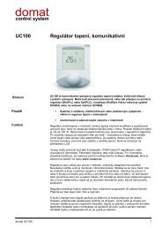
MODBUS UC100 <strong>Room</strong> controller V3<br />
UC100 – room controller, knob + RTC<br />
23<br />
- 60 words can be read at the same time (i.e. 120 bytes)<br />
- whole range can be addressed bitwise<br />
name address type description notes / defaults<br />
module ID 1 LSB R module type identification 0300hex<br />
1 MSB<br />
firmware 2 LSB<br />
2 MSB<br />
R firmware version old LCD displays:<br />
less than 100<br />
new LCD displays:<br />
100 <strong>and</strong> above (PCB<br />
status LSB 3 LSB R, W RAM module status lower byte<br />
bit 0 – write to EEPROM enabled<br />
bit 4 – init EEPROM<br />
status MSB 3 MSB R, RAM module status upper byte<br />
bit 0 0: normal mode<br />
1: init mode<br />
bit 1<br />
address 4 LSB R,W<br />
EEPROM<br />
baud rate 4 MSB R,W<br />
EEPROM<br />
serial port<br />
settings<br />
5 LSB R,W<br />
EEPROM<br />
1: at the next EEPROM<br />
write attempt will all data<br />
be written to EEPROM<br />
0: at the next EEPROM<br />
write attempt will all data<br />
be written to RAM only<br />
bit 2 – 1 – EEPROM initialized<br />
bit 3 – N/A<br />
bit 4 – 0<br />
bit 5 – 1<br />
bit 6 – 0<br />
bit 7 – commissioning mode<br />
(1...active)<br />
Modbus module address<br />
(default = 1)<br />
5 MSB reserved<br />
communication speed<br />
10dec … 1 200 bps<br />
11dec … 2 400 bps<br />
12dec … 4 800 bps<br />
13dec … 9 600 bps (default)<br />
14dec … 19 200 bps<br />
15dec … 38 400 bps<br />
16dec … 57 600 bps<br />
17dec … 115 200 bps<br />
serial line parameter settings<br />
(default = no parity, 1 stop bit)<br />
V1.6 <strong>and</strong> above)<br />
Init EEPROM follows if<br />
the INIT switch was ON at<br />
power up, <strong>and</strong> if INIT<br />
switch was OFF at setting<br />
bit 4 to 1 (indicated by bit<br />
2 in Status MSB)<br />
!!! the change will be<br />
effective after restart only<br />
(however the register will<br />
be set immediately)<br />
!!! the change will be<br />
effective after restart only<br />
(however the register will<br />
be set immediately)<br />
bit 0-1 ... parity (00 – no<br />
parity, 01 – even, 10 –<br />
odd)<br />
bit 2 ... stop bits (0 – one,<br />
1 - two)<br />
!!! the change will be<br />
effective after restart only<br />
(however the register will<br />
be set immediately)
MODBUS UC100 <strong>Room</strong> controller V3<br />
6 LSB<br />
reserved<br />
6 MSB<br />
relay 7 LSB R, RAM output relay status (DO1) bit 0 ... relay 1, heating<br />
inputs 7 MSB R, RAM binary heating / cooling dem<strong>and</strong>s bit 0-1 ... reserved<br />
bit 2 ... heating dem<strong>and</strong><br />
(PID output heat > 5%)<br />
bit 3 ... ... cooling dem<strong>and</strong><br />
(PID output cool > 5%)<br />
pid output HEAT 8 LSB R, RAM heating controller output in %, range 0 .. 100%<br />
pid output<br />
COOL<br />
8 MSB R, RAM cooling controller output in the<br />
change-over mode<br />
9 LSB reserved<br />
9 MSB reserved<br />
manual control 10 LSB R, W RAM manual output control; if a bit is set<br />
to 1, the output goes to state<br />
defined below (see manual heat<br />
output); if set to 0, PID output<br />
values apply<br />
10 MSB R, W RAM reserved<br />
manual heat<br />
output<br />
set temp<br />
correction<br />
11 LSB R, W RAM manual heat output setting (only if<br />
the corresponding bit in the<br />
manual control register is set)<br />
11 MSB R, W RAM reserved<br />
12 LSB<br />
12 MSB<br />
R, W RAM setpoint correction set by user;<br />
resets at each operation mode<br />
change<br />
in %, range 0 .. 100%<br />
bit 0 ... reserved<br />
bit 1 ... heat output<br />
bit 2 – 4 reserved<br />
bit 5 ... change over (1 =<br />
c/o active)<br />
in %, range 0 .. 100%<br />
recalculate:<br />
temperature =<br />
read value / 100<br />
actual temp set<br />
point HEAT<br />
13 LSB<br />
13 MSB<br />
3.5°C reads 350<br />
(limits are set in the min <strong>and</strong> max<br />
rel. temp correction registers)<br />
R, RAM actual heating setpoint incl.<br />
setpoint correction (reg. 12)<br />
0 … 0<br />
199.99 … 19999<br />
-0.01 … 0FFFFhex<br />
-199.99 … 0B1E1hex<br />
recalculate:<br />
temperature =<br />
read value / 100<br />
actual temp set<br />
point COOL<br />
14 LSB<br />
14 MSB<br />
R, RAM actual cooling setpoint incl.<br />
setpoint correction (reg. 12)<br />
0 … 0<br />
199.99 … 19999<br />
-0.01 … 0FFFFhex<br />
-199.99 … 0B1E1hex<br />
recalculate:<br />
temperature =<br />
read value / 100<br />
set day/ comfort<br />
heating temp<br />
15 LSB<br />
15 MSB<br />
R,W<br />
EEPROM<br />
day/comfort mode heating<br />
temperature setpoint<br />
set by user<br />
0 … 0<br />
199.99 … 19999<br />
-0.01 … 0FFFFhex<br />
-199.99 … 0B1E1hex<br />
recalculate:<br />
temperature =<br />
read value / 100<br />
(default = 21°C, 0x0834)<br />
0 … 0<br />
199.99 … 19999<br />
-0.01 … 0FFFFhex<br />
-199.99 … 0B1E1hex<br />
24
MODBUS UC100 <strong>Room</strong> controller V3<br />
set night/ precomfort<br />
heating<br />
temp<br />
16 LSB<br />
16 MSB<br />
R,W<br />
EEPROM<br />
night/st<strong>and</strong>by mode heating<br />
temperature setpoint<br />
set by user<br />
recalculate:<br />
temperature =<br />
read value / 100<br />
set depression/<br />
economy heating<br />
temp<br />
17 LSB<br />
17 MSB<br />
R,W<br />
EEPROM<br />
(default = 19°C, 0x076C)<br />
off mode heating temperature<br />
setpoint<br />
set by user<br />
0 … 0<br />
199.99 … 19999<br />
-0.01 … 0FFFFhex<br />
-199.99 … 0B1E1hex<br />
recalculate:<br />
temperature =<br />
read value / 100<br />
set day/ comfort<br />
cooling temp<br />
18 LSB<br />
18 MSB<br />
R,W<br />
EEPROM<br />
(default = 12°C, 0x04B0)<br />
day/comfort mode cooling<br />
temperature setpoint<br />
set by user<br />
0 … 0<br />
199.99 … 19999<br />
-0.01 … 0FFFFhex<br />
-199.99 … 0B1E1hex<br />
recalculate:<br />
temperature =<br />
read value / 100<br />
set night/ precomfort<br />
cooling<br />
temp<br />
19 LSB<br />
19 MSB<br />
R,W<br />
EEPROM<br />
(default = 24°C, 0x0960)<br />
night/st<strong>and</strong>by mode cooling<br />
temperature setpoint<br />
set by user<br />
0 … 0<br />
199.99 … 19999<br />
-0.01 … 0FFFFhex<br />
-199.99 … 0B1E1hex<br />
recalculate:<br />
temperature =<br />
read value / 100<br />
set depression/<br />
economy cooling<br />
temp<br />
20 LSB<br />
20 MSB<br />
R, W<br />
EEPROM<br />
(default = 26°C, 0x0A28)<br />
off mode cooling temperature<br />
setpoint<br />
set by user<br />
0 … 0<br />
199.99 … 19999<br />
-0.01 … 0FFFFhex<br />
-199.99 … 0B1E1hex<br />
recalculate:<br />
temperature =<br />
read value / 100<br />
actual temp<br />
21 LSB<br />
21 MSB<br />
(default = 35°C, 0x0DAC)<br />
R, RAM actual temperature measured by<br />
the internal sensor incl. correction<br />
(see corr temp)<br />
0 … 0<br />
199.99 … 19999<br />
-0.01 … 0FFFFhex<br />
-199.99 … 0B1E1hex<br />
recalculate:<br />
temperature =<br />
read value / 100<br />
0 … 0<br />
199.99 … 19999<br />
-0.01 … 0FFFFhex<br />
-199.99 … 0B1E1hex<br />
actual outside<br />
temp<br />
22 LSB<br />
22 MSB<br />
R, W RAM actual outside temperature, may<br />
be written to RAM optionally for<br />
display<br />
recalculate:<br />
temperature =<br />
read value / 100<br />
0 … 0<br />
199.99 … 19999<br />
-0.01 … 0FFFFhex<br />
-199.99 … 0B1E1hex<br />
25
MODBUS UC100 <strong>Room</strong> controller V3<br />
set presence<br />
mode<br />
23 LSB<br />
23 MSB<br />
24 LSB<br />
24 MSB<br />
R,W<br />
EEPROM<br />
presence status set by user<br />
(displayed symbols depend on the<br />
configuration register regulator<br />
settings, if set to hotel then<br />
comfort, st<strong>and</strong>by, off; if set to<br />
residential then day, night,<br />
depression, auto, party)<br />
(default = comfort/day, 0x0001)<br />
reserved<br />
bit 0 … comfort (occupied<br />
house) or day (sun +<br />
occupied house)<br />
bit 1 … st<strong>and</strong>by (empty<br />
house) or night (moon +<br />
occupied house)<br />
bit 2 … off (off) or<br />
depression (empty house)<br />
bit 3 … auto (clock) – only<br />
when residential<br />
bit 4 … party (sun + drink<br />
+ clock, after 2h goes to<br />
auto) – only when<br />
residential<br />
bit 5 to 14 ... reserved<br />
bit 15 ... write enable (if<br />
set to 1 value will be<br />
written into register, if in 0<br />
attempt will be ignored)<br />
actual control<br />
mode<br />
regulator<br />
settings<br />
25 LSB R, RAM actual mode used for control, if on<br />
manual then the actual control<br />
mode is equal to set presence<br />
mode, if on auto then according to<br />
time schedule<br />
(displayed symbols depend on the<br />
configuration register regulator<br />
settings, if set to hotel then<br />
comfort, st<strong>and</strong>by, off; if set to<br />
residential then day, night,<br />
depression, auto, party)<br />
25 MSB reserved<br />
26 LSB R,W<br />
controller configuration<br />
EEPROM<br />
26 MSB reserved<br />
(defaults = residential, absolute,<br />
valve status, valve protection on,<br />
PI control, 0x13)<br />
bit 0 … comfort/day<br />
bit 1 … st<strong>and</strong>by/night<br />
bit 2 … off/depression<br />
bit 0 ... presence mode<br />
type (0 – hotel, 1 -<br />
residential)<br />
bit 1 … temperature<br />
correction display<br />
(0 –relative, 1 – absolute)<br />
bit 2 ... heating/cooling<br />
symbols display: 1 –<br />
media status according to<br />
the c/o signal, 0 – valve<br />
status)<br />
bit 3 ... reserved<br />
bit 4 ... valve exercising<br />
(1 – enabled)<br />
bit 5 ... valve polarity (0 –<br />
NC, 1 – NO)<br />
bit 6 ... temp. correction<br />
reset when control mode<br />
(reg. 25 LSB) changes<br />
bit 7 ... control mode (0 –<br />
PI, 1 – on/off)<br />
26
MODBUS UC100 <strong>Room</strong> controller V3<br />
P b<strong>and</strong><br />
27 LSB<br />
27 MSB<br />
R,W<br />
EEPROM<br />
controller P-b<strong>and</strong> (PI control<br />
mode) or hysteresis (on/off control<br />
mode)<br />
in 0.1 K<br />
(2 K, 0x0014)<br />
I const<br />
28 LSB<br />
28 MSB<br />
R,W<br />
EEPROM<br />
controller I – constant; if out of<br />
bounds, a new recalculated value<br />
is set after restart<br />
in seconds; if set to 0,<br />
integration part is<br />
disabled<br />
min rel. temp<br />
correction<br />
29 LSB<br />
29 MSB<br />
30 LSB<br />
30 MSB<br />
31 LSB<br />
31 MSB<br />
32 LSB<br />
32 MSB<br />
33 LSB<br />
33 MSB<br />
R,W<br />
EEPROM<br />
reserved<br />
reserved<br />
reserved<br />
reserved<br />
minimum relative user temperature<br />
correction, a positive value is<br />
saved <strong>and</strong> is taken as negative<br />
limit<br />
(60 min, 0x0E10)<br />
recalculate:<br />
minimum correction =<br />
-(read value/100);<br />
-10.00 … 1000<br />
(-3.5 °C, 0x015E)<br />
max rel. temp<br />
correction<br />
34 LSB<br />
34 MSB<br />
R,W<br />
EEPROM<br />
maximum relative user<br />
temperature correction<br />
recalculate:<br />
maximum correction =<br />
(read value/100);<br />
10.00 … 1000<br />
(3.5 °C, 0x015E)<br />
min day, night,<br />
depression temp<br />
max day, night,<br />
depression temp<br />
sensor corr temp<br />
35 LSB<br />
35 MSB<br />
36 MSB<br />
36 MSB<br />
37 MSB<br />
37 MSB<br />
38 MSB<br />
38 MSB<br />
R,W<br />
EEPROM<br />
R,W<br />
EEPROM<br />
R,W<br />
EEPROM<br />
minimum temperature which user<br />
can set as setpoint for day, night,<br />
<strong>and</strong> off modes<br />
-199.99 to 199.99<br />
(default = 10 °C, 0x03E8)<br />
maximum temperature which user<br />
can set as setpoint for day, night,<br />
<strong>and</strong> off modes<br />
-199.99 to 199.99<br />
(default = 40 °C, 0x0FA0)<br />
correction: adds to the actual<br />
temperature measured by the<br />
internal sensor<br />
-20.00 to 20.00<br />
(default = -1,5 K, 0xFF6A)<br />
reserved<br />
recalculate:<br />
temperature<br />
= read value / 100<br />
0 … 0<br />
199.99 … 19999<br />
-0.01 … 0FFFFhex<br />
-199.99 … 0B1E1hex<br />
recalculate:<br />
temperature<br />
= read value / 100<br />
0 … 0<br />
199.99 … 19999<br />
-0.01 … 0FFFFhex<br />
-199.99 … 0B1E1hex<br />
recalculate:<br />
temperature<br />
= read value / 100<br />
0 … 0<br />
199.99 … 19999<br />
-0.01 … 0FFFFhex<br />
-199.99 … 0B1E1hex<br />
27
MODBUS UC100 <strong>Room</strong> controller V3<br />
step temp 39 LSB R,W<br />
EEPROM<br />
step minutes 39 MSB R,W<br />
EEPROM<br />
show mode<br />
40 LSB<br />
40 MSB<br />
41 LSB<br />
41 MSB<br />
R,W<br />
EEPROM<br />
show time 42 LSB R,W<br />
EEPROM<br />
edit return time 42 MSB R,W<br />
EEPROM<br />
quick edit mode<br />
number<br />
change over<br />
period<br />
43 LSB R,W<br />
EEPROM<br />
43 MSB R,W<br />
EEPROM<br />
long push time 44 LSB R,W<br />
EEPROM<br />
step for user temperature<br />
setpoints setting<br />
(default = 0.5 °C, 0x32)<br />
time step for time schedule setting<br />
(default = 5 mins, 0x05)<br />
reserved<br />
data that roll on the LCD display<br />
(default = 1)<br />
If only one of the bits is active<br />
there is only one value displayed.<br />
Otherwise they change<br />
periodically after show time.<br />
time (in 100 ms) to display each<br />
value in show mode (default = 3 s,<br />
0x1E)<br />
time (in s) of user inactivity to<br />
return from edit mode to show<br />
mode (default = 30 s, 0x1E)<br />
number of mode which is editable<br />
through quick edit menu (short<br />
push of the knob)<br />
(default = 0x01)<br />
time delay when changing from<br />
heating to cooling <strong>and</strong> back<br />
(default = 30)<br />
time (in 100 ms) evaluated as long<br />
push (go to time schedule menu /<br />
leave menu)<br />
step = read value / 100<br />
1 … 0.01<br />
50 … 0.5<br />
100 … 1 etc.<br />
in minutes<br />
bit 0 … temperature<br />
bit 1 … outside temp.<br />
bit 2 … current time<br />
(default = temperature,<br />
0x0001)<br />
see show mode<br />
0 ... push function inactive<br />
1 ... presence mode<br />
2 ... reserved<br />
in mins, 1 to 255<br />
for editing of the time<br />
schedule <strong>and</strong> presence or<br />
fan mode<br />
super long push<br />
time<br />
44 MSB R,W<br />
EEPROM<br />
(default = 1.5 s, 0x0F)<br />
time (in 100 ms) evaluated as<br />
superlong push (go to settings<br />
menu)<br />
for actual time <strong>and</strong> basic<br />
setpoints settings<br />
allowed<br />
operation modes<br />
45 LSB<br />
45 MSB<br />
R,W<br />
EEPROM<br />
(default = 5 s, 0x32)<br />
settings that user is able to<br />
perform<br />
0 … disabled<br />
1 … enabled<br />
(default = temp corr, RTC time,<br />
presence mode, time programme<br />
0x0581)<br />
bit 0 … temp corr.<br />
bit 1 … heating day temp<br />
bit 2 … heating night<br />
temp<br />
bit 3 … heating<br />
depression temp<br />
bit 4 … cooling day temp<br />
bit 5 … cooling night temp<br />
bit 6 … cooling<br />
depression temp<br />
bit 7 … RTC time<br />
bit 8 … presence mode<br />
bit 9 … reserved<br />
bit 10 … time programme<br />
28
MODBUS UC100 <strong>Room</strong> controller V3<br />
presence mode<br />
edit mask<br />
display symbols<br />
RTC<br />
program Monday<br />
Event 1 time<br />
46 LSB<br />
46 MSB<br />
47 LSB<br />
47 MSB<br />
48 LSB<br />
48 MSB<br />
49 LSB<br />
49 MSB<br />
50 LSB<br />
50 MSB<br />
51 LSB<br />
51 MSB<br />
52 LSB<br />
52 MSB<br />
53 LSB<br />
53 MSB<br />
54 LSB<br />
54 MSB<br />
R,W<br />
EEPROM<br />
states in presence mode that user<br />
is able to switch between<br />
(default = all, 0x001F)<br />
reserved<br />
bit 0 … day (sun +<br />
occupied house)<br />
bit 1 … night (moon +<br />
occupied house)<br />
bit 2 … depression<br />
(empty house)<br />
bit 3 … auto (clock)<br />
bit 4 … party (sun + drink<br />
+ clock, after 2h goes to<br />
auto)<br />
R,W RAM displayed symbols bit 0 … spanner<br />
bit 1 … boiler<br />
bit 2 … alarm bell<br />
bit 3 to 14 ... reserved<br />
bit 15 ... write enable<br />
write enable (if set to 1<br />
value will be written into<br />
register, if in 0 attempt will<br />
be ignored)<br />
R,W<br />
EEPROM<br />
R,W<br />
EEPROM<br />
Real time clock<br />
(not subject to INIT comm<strong>and</strong>)<br />
reserved<br />
time schedule, Monday, time of<br />
event No. 1, in mins since 0:00<br />
(midnight)<br />
see table;<br />
to write to those registers,<br />
write to EEPROM must<br />
be enabled in the status<br />
LSB register<br />
e.g. 121 ... 2h 1min<br />
program Monday<br />
Event 1 value<br />
program Monday<br />
Event 2 time<br />
55 LSB<br />
55 MSB<br />
56 LSB<br />
56 MSB<br />
R,W<br />
EEPROM<br />
R,W<br />
EEPROM<br />
(default = 06:00 h, 0x0168)<br />
time schedule, Monday, event No.<br />
1, value<br />
(default = 0)<br />
time schedule, Monday, time of<br />
event No. 2, in mins since 0:00<br />
(midnight)<br />
0 ... day/comfort<br />
1 ... night/st<strong>and</strong>by<br />
2 ... off/depression<br />
bit 15 = 1 ... event is<br />
disabled<br />
e.g. 121 ... 2h 1min<br />
program Monday<br />
Event 2 value<br />
program Monday<br />
Event 3 time<br />
57 LSB<br />
57 MSB<br />
58 LSB<br />
58 MSB<br />
R,W<br />
EEPROM<br />
R,W<br />
EEPROM<br />
(default = 08:00 h)<br />
time schedule, Monday, event No.<br />
2, value<br />
(default = 1)<br />
time schedule, Monday, time of<br />
event No. 3, in mins since 0:00<br />
(midnight)<br />
0 ... day/comfort<br />
1 ... night/st<strong>and</strong>by<br />
2 ... off/depression<br />
bit 15 = 1 ... event is<br />
disabled<br />
e.g. 121 ... 2h 1min<br />
(default = 14:00 h)<br />
29
MODBUS UC100 <strong>Room</strong> controller V3<br />
program Monday<br />
Event 3 value<br />
program Monday<br />
Event 4 time<br />
59 LSB<br />
59 MSB<br />
60 LSB<br />
60 MSB<br />
R,W<br />
EEPROM<br />
R,W<br />
EEPROM<br />
time schedule, Monday, event No.<br />
3, value<br />
(default = 0)<br />
time schedule, Monday, time of<br />
event No. 4, in mins since 0:00<br />
(midnight)<br />
0 ... day/comfort<br />
1 ... night/st<strong>and</strong>by<br />
2 ... off/depression<br />
bit 15 = 1 ... event is<br />
disabled<br />
e.g. 121 ... 2h 1min<br />
program Monday<br />
Event 4 value<br />
program Monday<br />
Event 5 time<br />
61 LSB<br />
61 MSB<br />
62 LSB<br />
62 MSB<br />
R,W<br />
EEPROM<br />
R,W<br />
EEPROM<br />
(default = 22:00 h)<br />
time schedule, Monday, event No.<br />
4, value<br />
(default = 1)<br />
time schedule, Monday, time of<br />
event No. 5, in mins since 0:00<br />
(midnight)<br />
0 ... day/comfort<br />
1 ... night/st<strong>and</strong>by<br />
2 ... off/depression<br />
bit 15 = 1 ... event is<br />
disabled<br />
e.g. 121 ... 2h 1min<br />
program Monday<br />
Event 5 value<br />
program Monday<br />
Event 6 time<br />
63 LSB<br />
63 MSB<br />
64 LSB<br />
64 MSB<br />
R,W<br />
EEPROM<br />
R,W<br />
EEPROM<br />
(default = 06:00 h, 0x0168)<br />
time schedule, Monday, event No.<br />
5, value<br />
(default = disabled, 0x8000)<br />
time schedule, Monday, time of<br />
event No. 6, in mins since 0:00<br />
(midnight)<br />
0 ... day/comfort<br />
1 ... night/st<strong>and</strong>by<br />
2 ... off/depression<br />
bit 15 = 1 ... event is<br />
disabled<br />
e.g. 121 ... 2h 1min<br />
program Monday<br />
Event 6 value<br />
program<br />
Tuesday Event 1<br />
time<br />
65 LSB<br />
65 MSB<br />
66 LSB<br />
66 MSB<br />
R,W<br />
EEPROM<br />
R,W<br />
EEPROM<br />
(default = 06:00 h)<br />
time schedule, Monday, event No.<br />
6, value<br />
(default = disabled)<br />
time schedule, Tuesday, time of<br />
event No. 1, in mins since 0:00<br />
(midnight)<br />
0 ... day/comfort<br />
1 ... night/st<strong>and</strong>by<br />
2 ... off/depression<br />
bit 15 = 1 ... event is<br />
disabled<br />
e.g. 121 ... 2h 1min<br />
(default = 06:00 h)<br />
... ... ... ... ...<br />
program Sunday<br />
Event 6 value<br />
137 LSB<br />
137 MSB<br />
R,W<br />
EEPROM<br />
time schedule, Sunday, event No.<br />
6, value<br />
(default = disabled)<br />
0 ... day/comfort<br />
1 ... night/st<strong>and</strong>by<br />
2 ... off/depression<br />
bit 15 = 1 ... event is<br />
disabled<br />
uptime<br />
1000 LSB<br />
1000 MSB<br />
1001 LSB<br />
1001 MSB<br />
R uptime (s) number of seconds after<br />
last power on / reset<br />
30
MODBUS UC100 <strong>Room</strong> controller V3<br />
Real time table<br />
Addr. bit7 bit6 bit5 bit4 bit3 bit2 bit1 bit0 Function Range<br />
49 LSB 10xsecs<br />
seconds<br />
secs 00-59<br />
49 MSB 0 10xmins<br />
minutes<br />
mins 00-59<br />
50 LSB 0<br />
10xhours<br />
10xhours<br />
hours<br />
hours 00-23<br />
50MSB 0 0 0 0 0 day<br />
day 01-07<br />
51 LSB 0 0 10xdate<br />
date<br />
date 01-31<br />
51 MSB 0 0 0 10xmonth month<br />
month 01-12<br />
52 LSB 10xyear<br />
year<br />
year 00-99<br />
52 MSB 0 0 0 0 0 0 0 0 not used 00<br />
Commissioning mode: when powered on with pushbutton pushed, after several seconds the<br />
commissioning mode is activated with manual control over outputs <strong>and</strong> indication of inputs. After<br />
10 mins after last push or after reboot the controller goes to normal (control) mode. Inthe<br />
commissioning mode, all Modbus data are read-only.<br />
31
MODBUS UC200 <strong>Room</strong> controller V3<br />
UC200 – room controller, heating <strong>and</strong> cooling, knob + RTC<br />
32<br />
- 60 words can be read at the same time (i.e. 120 bytes)<br />
- whole range can be addressed bitwise<br />
name address type description notes / defaults<br />
module ID 1 LSB R module type identification 0301hex<br />
1 MSB<br />
firmware 2 LSB<br />
2 MSB<br />
R firmware version old LCD displays:<br />
less than 100<br />
new LCD displays:<br />
100 <strong>and</strong> above (PCB<br />
status LSB 3 LSB R, W RAM module status lower byte<br />
bit 0 – write to EEPROM enabled<br />
bit 4 – init EEPROM<br />
status MSB 3 MSB R, RAM module status upper byte<br />
bit 0 0: normal mode<br />
1: init mode<br />
bit 1<br />
address 4 LSB R,W<br />
EEPROM<br />
baud rate 4 MSB R,W<br />
EEPROM<br />
serial port<br />
settings<br />
5 LSB R,W<br />
EEPROM<br />
1: at the next EEPROM<br />
write attempt will all data<br />
be written to EEPROM<br />
0: at the next EEPROM<br />
write attempt will all data<br />
be written to RAM only<br />
bit 2 – 1 – EEPROM initialized<br />
bit 3 – N/A<br />
bit 4 – 0<br />
bit 5 – 1<br />
bit 6 – 0<br />
bit 7 – commissioning mode (1 ...<br />
active)<br />
Modbus module address<br />
(default = 1)<br />
communication<br />
10dec … 1 200 bps<br />
11dec … 2 400 bps<br />
12dec … 4 800 bps<br />
13dec … 9 600 bps (default)<br />
14dec … 19 200 bps<br />
15dec … 38 400 bps<br />
16dec … 57 600 bps<br />
17dec … 115 200 bps<br />
serial line parameter settings<br />
(default = no parity, 1 stop bit)<br />
V1.6 <strong>and</strong> above)<br />
Init EEPROM follows if<br />
the INIT switch was ON at<br />
power up, <strong>and</strong> if INIT<br />
switch was OFF at setting<br />
bit 4 to 1 (indicated by bit<br />
2 in Status MSB)<br />
!!! the change will be<br />
effective after restart only<br />
(however the register will<br />
be set immediately)<br />
!!! the change will be<br />
effective after restart only<br />
(however the register will<br />
be set immediately)<br />
bit 0-1 ... parity (00 – no<br />
parity, 01 – even, 10 –<br />
odd)<br />
bit 2 ... stop bits (0 – one,<br />
1 - two)<br />
!!! the change will be<br />
effective after restart only<br />
(however the register will<br />
be set immediately)
MODBUS UC200 <strong>Room</strong> controller V3<br />
5 MSB reserved<br />
6 LSB<br />
reserved<br />
6 MSB<br />
relay 7 LSB R, RAM output relay status (DO1, DO2) bit 0 ... relay 1, heating<br />
bit 1 ... relay 2, cooling<br />
inputs 7 MSB R, RAM input states, binary heating /<br />
cooling dem<strong>and</strong>s.<br />
DI1 <strong>and</strong> DI2 are physical input<br />
states regardless of the inputs<br />
settings setting.<br />
bit 0 ... DI1<br />
bit 1 ... DI2<br />
bit 2 ... heating dem<strong>and</strong><br />
(PID output heat > 5%)<br />
bit 3 ... cooling dem<strong>and</strong><br />
(PID output cool > 5%)<br />
pid output HEAT 8 LSB R, RAM heating controller output in %, range 0 .. 100%<br />
pid output<br />
COOL<br />
8 MSB R, RAM cooling controller output in %, range 0 .. 100%<br />
9 LSB reserved<br />
9 MSB reserved<br />
manual control 10 LSB R, W RAM manual output control; if a bit is set<br />
to 1, the output goes to state<br />
defined below (see manual heat<br />
output, manual cool output); if<br />
set to 0, PID output values apply<br />
10 MSB R, W RAM reserved<br />
manual heat<br />
output<br />
manual cool<br />
output<br />
set temp<br />
correction<br />
11 LSB R, W RAM manual heat output setting (only if<br />
the corresponding bit in the<br />
manual control register is set)<br />
11 MSB R, W RAM manual cool output setting (only if<br />
the corresponding bit in the<br />
12 LSB<br />
12 MSB<br />
manual control register is set)<br />
R, W RAM setpoint correction set by user;<br />
resets at each operation mode<br />
change<br />
bit 0 ... reserved<br />
bit 1 ... heat output<br />
bit 2 ... cool output<br />
in %, range 0 .. 100%<br />
in %, range 0 .. 100%<br />
recalculate:<br />
temperature =<br />
read value / 100<br />
actual temp set<br />
point HEAT<br />
13 LSB<br />
13 MSB<br />
3.5°C reads 350<br />
(limits are set in the min <strong>and</strong> max<br />
rel. temp correction registers)<br />
R, RAM actual heating setpoint incl.<br />
setpoint correction (reg. 12)<br />
0 … 0<br />
199.99 … 19999<br />
-0.01 … 0FFFFhex<br />
-199.99 … 0B1E1hex<br />
recalculate:<br />
temperature =<br />
read value / 100<br />
actual temp set<br />
point COOL<br />
14 LSB<br />
14 MSB<br />
R, RAM actual cooling setpoint incl.<br />
setpoint correction (reg. 12)<br />
0 … 0<br />
199.99 … 19999<br />
-0.01 … 0FFFFhex<br />
-199.99 … 0B1E1hex<br />
recalculate:<br />
temperature =<br />
read value / 100<br />
0 … 0<br />
199.99 … 19999<br />
-0.01 … 0FFFFhex<br />
-199.99 … 0B1E1hex<br />
33
MODBUS UC200 <strong>Room</strong> controller V3<br />
set day/ comfort<br />
heating temp<br />
15 LSB<br />
15 MSB<br />
R,W<br />
EEPROM<br />
day/comfort mode heating<br />
temperature setpoint<br />
set by user<br />
recalculate:<br />
temperature =<br />
read value / 100<br />
set night/ precomfort<br />
heating<br />
temp<br />
16 LSB<br />
16 MSB<br />
R,W<br />
EEPROM<br />
(default = 21°C, 0x0834)<br />
night/st<strong>and</strong>by mode heating<br />
temperature setpoint<br />
set by user<br />
0 … 0<br />
199.99 … 19999<br />
-0.01 … 0FFFFhex<br />
-199.99 … 0B1E1hex<br />
recalculate:<br />
temperature =<br />
read value / 100<br />
set depression/<br />
economy heating<br />
temp<br />
17 LSB<br />
17 MSB<br />
R,W<br />
EEPROM<br />
(default = 19°C, 0x076C)<br />
off mode heating temperature<br />
setpoint<br />
set by user<br />
0 … 0<br />
199.99 … 19999<br />
-0.01 … 0FFFFhex<br />
-199.99 … 0B1E1hex<br />
recalculate:<br />
temperature =<br />
read value / 100<br />
set day/ comfort<br />
cooling temp<br />
18 LSB<br />
18 MSB<br />
R,W<br />
EEPROM<br />
(default = 12°C, 0x04B0)<br />
day/comfort mode cooling<br />
temperature setpoint<br />
set by user<br />
0 … 0<br />
199.99 … 19999<br />
-0.01 … 0FFFFhex<br />
-199.99 … 0B1E1hex<br />
recalculate:<br />
temperature =<br />
read value / 100<br />
set night/ precomfort<br />
cooling<br />
temp<br />
19 LSB<br />
19 MSB<br />
R,W<br />
EEPROM<br />
(default = 24°C, 0x0960)<br />
night/st<strong>and</strong>by mode cooling<br />
temperature setpoint<br />
set by user<br />
0 … 0<br />
199.99 … 19999<br />
-0.01 … 0FFFFhex<br />
-199.99 … 0B1E1hex<br />
recalculate:<br />
temperature =<br />
read value / 100<br />
set depression/<br />
economy cooling<br />
temp<br />
20 LSB<br />
20 MSB<br />
R, W<br />
EEPROM<br />
(default = 26°C, 0x0A28)<br />
off mode cooling temperature<br />
setpoint<br />
set by user<br />
0 … 0<br />
199.99 … 19999<br />
-0.01 … 0FFFFhex<br />
-199.99 … 0B1E1hex<br />
recalculate:<br />
temperature =<br />
read value / 100<br />
actual temp<br />
21 LSB<br />
21 MSB<br />
(default = 35°C, 0x0DAC)<br />
R, RAM actual temperature measured by<br />
the internal sensor incl. correction<br />
(see corr temp)<br />
0 … 0<br />
199.99 … 19999<br />
-0.01 … 0FFFFhex<br />
-199.99 … 0B1E1hex<br />
recalculate:<br />
temperature =<br />
read value / 100<br />
0 … 0<br />
199.99 … 19999<br />
-0.01 … 0FFFFhex<br />
-199.99 … 0B1E1hex<br />
34
MODBUS UC200 <strong>Room</strong> controller V3<br />
actual outside<br />
temp<br />
22 LSB<br />
22 MSB<br />
R, W RAM actual outside temperature, may<br />
be written to RAM optionally for<br />
display<br />
recalculate:<br />
temperature =<br />
read value / 100<br />
0 … 0<br />
199.99 … 19999<br />
-0.01 … 0FFFFhex<br />
-199.99 … 0B1E1hex<br />
set presence<br />
mode<br />
23 LSB<br />
23 MSB<br />
24 LSB<br />
24 MSB<br />
R,W<br />
EEPROM<br />
presence status set by user<br />
(displayed symbols depend on the<br />
configuration register regulator<br />
settings, if set to hotel then<br />
comfort, st<strong>and</strong>by, off; if set to<br />
residential then day, night,<br />
depression, auto, party)<br />
(default = comfort/day, 0x0001)<br />
reserved<br />
bit 0 … comfort (occupied<br />
house) or day (sun +<br />
occupied house)<br />
bit 1 … st<strong>and</strong>by (empty<br />
house) or night (moon +<br />
occupied house)<br />
bit 2 … off (off) or<br />
depression (empty house)<br />
bit 3 … auto (clock) – only<br />
when residential<br />
bit 4 … party (sun + drink<br />
+ clock, after 2h goes to<br />
auto) – only when<br />
residential<br />
bit 5 to 14 ... reserved<br />
bit 15 ... write enable (if<br />
set to 1 value will be<br />
written into register, if in 0<br />
attempt will be ignored)<br />
actual control<br />
mode<br />
25 LSB R, RAM actual mode used for control, if on<br />
manual then the actual control<br />
mode is equal to set presence<br />
mode, if on auto then according to<br />
time schedule<br />
(displayed symbols depend on the<br />
configuration register regulator<br />
settings, if set to hotel then<br />
comfort, st<strong>and</strong>by, off; if set to<br />
residential then day, night,<br />
depression, auto, party)<br />
25 MSB reserved<br />
bit 0 … comfort/day<br />
bit 1 … st<strong>and</strong>by/night<br />
bit 2 … off/depression<br />
35
MODBUS UC200 <strong>Room</strong> controller V3<br />
regulator<br />
settings<br />
26 LSB R,W<br />
EEPROM<br />
input settings 26 MSB R, W,<br />
EEPROM<br />
P b<strong>and</strong><br />
27 LSB<br />
27 MSB<br />
R,W<br />
EEPROM<br />
controller configuration<br />
(defaults = hotel, relative, valve<br />
status, valve protection on, NC<br />
valves, PI control, 0x10)<br />
input configuration<br />
DI1 – presence<br />
DI2 – window contact<br />
default: inputs enabled for control,<br />
active when on, 0x0F<br />
controller P-b<strong>and</strong> (PI control<br />
mode) or hysteresis (on/off control<br />
mode)<br />
bit 0 ... presence mode<br />
type (0 – hotel, 1 -<br />
residential)<br />
bit 1 … temperature<br />
correction display<br />
(0 –relative, 1 – absolute)<br />
bit 2 ... heating/cooling<br />
symbols display: 1 –<br />
media status according to<br />
the c/o signal, 0 – valve<br />
status)<br />
bit 3 ... reserved<br />
bit 4 ... valve exercising<br />
(1 – enabled)<br />
bit 5 ... valve polarity (0 –<br />
NC, 1 – NO)<br />
bit 6 ... temp. correction<br />
reset when control mode<br />
changes (0 ... no, 1 ...<br />
yes)<br />
bit 7 ... control mode (0 –<br />
PI, 1 – on/off)<br />
bit 0 ... DI enabled<br />
bit 1 ... DI2 enabled<br />
bit 2 ... DI1 sense (0: NC,<br />
1: NO)<br />
bit 3 ... DI2 sense (0: NC,<br />
1: NO)<br />
in 0.1 K<br />
(2 K, 0x0014)<br />
I const<br />
28 LSB<br />
28 MSB<br />
R,W<br />
EEPROM<br />
controller I – constant; if out of<br />
bounds, a new recalculated value<br />
is set after restart<br />
in seconds; if set to 0,<br />
integration part is<br />
disabled<br />
min rel. temp<br />
correction<br />
29 LSB<br />
29 MSB<br />
30 LSB<br />
30 MSB<br />
31 LSB<br />
31 MSB<br />
32 LSB<br />
32 MSB<br />
33 LSB<br />
33 MSB<br />
R,W<br />
EEPROM<br />
reserved<br />
reserved<br />
reserved<br />
reserved<br />
minimum relative user temperature<br />
correction, a positive value is<br />
saved <strong>and</strong> is taken as negative<br />
limit<br />
(60 min, 0x0E10)<br />
recalculate:<br />
minimum correction =<br />
-(read value/100);<br />
-10.00 … 1000<br />
(-3.5 °C, 0x015E)<br />
36
MODBUS UC200 <strong>Room</strong> controller V3<br />
max rel. temp<br />
correction<br />
34 LSB<br />
34 MSB<br />
R,W<br />
EEPROM<br />
maximum relative user<br />
temperature correction<br />
recalculate:<br />
maximum correction =<br />
(read value/100);<br />
10.00 … 1000<br />
(3.5 °C, 0x015E)<br />
min day, night,<br />
depression temp<br />
max day, night,<br />
depression temp<br />
sensor corr temp<br />
35 LSB<br />
35 MSB<br />
36 MSB<br />
36 MSB<br />
37 MSB<br />
37 MSB<br />
38 MSB<br />
38 MSB<br />
R,W<br />
EEPROM<br />
R,W<br />
EEPROM<br />
R,W<br />
EEPROM<br />
step temp 39 LSB R,W<br />
EEPROM<br />
step minutes 39 MSB R,W<br />
EEPROM<br />
show mode<br />
40 LSB<br />
40 MSB<br />
41 LSB<br />
41 MSB<br />
R,W<br />
EEPROM<br />
show time 42 LSB R,W<br />
EEPROM<br />
edit return time 42 MSB R,W<br />
EEPROM<br />
minimum temperature which user<br />
can set as setpoint for day, night,<br />
<strong>and</strong> off modes<br />
-199.99 to 199.99<br />
(default = 10 °C, 0x03E8)<br />
maximum temperature which user<br />
can set as setpoint for day, night,<br />
<strong>and</strong> off modes<br />
-199.99 to 199.99<br />
(default = 40 °C, 0x0FA0)<br />
correction: adds to the actual<br />
temperature measured by the<br />
internal sensor<br />
-20.00 to 20.00<br />
(default = -1,5 K, 0xFF6A)<br />
reserved<br />
step for user temperature<br />
setpoints setting<br />
(default = 0.5 °C, 0x32)<br />
time step for time schedule setting<br />
(default = 5 mins, 0x05)<br />
reserved<br />
data that roll on the LCD display<br />
(default = 1)<br />
If only one of the bits is active<br />
there is only one value displayed.<br />
Otherwise they change<br />
periodically after show time.<br />
time (in 100 ms) to display each<br />
value in show mode (default = 3 s,<br />
0x1E)<br />
time (in s) of user inactivity to<br />
return from edit mode to show<br />
mode (default = 30 s, 0x1E)<br />
recalculate:<br />
temperature<br />
= read value / 100<br />
0 … 0<br />
199.99 … 19999<br />
-0.01 … 0FFFFhex<br />
-199.99 … 0B1E1hex<br />
recalculate:<br />
temperature<br />
= read value / 100<br />
0 … 0<br />
199.99 … 19999<br />
-0.01 … 0FFFFhex<br />
-199.99 … 0B1E1hex<br />
recalculate:<br />
temperature<br />
= read value / 100<br />
0 … 0<br />
199.99 … 19999<br />
-0.01 … 0FFFFhex<br />
-199.99 … 0B1E1hex<br />
step = read value / 100<br />
1 … 0.01<br />
50 … 0.5<br />
100 … 1 etc.<br />
in minutes<br />
bit 0 … temperature<br />
bit 1 … outside temp.<br />
bit 2 … current time<br />
(default = temperature,<br />
0x0001)<br />
see show mode<br />
37
MODBUS UC200 <strong>Room</strong> controller V3<br />
quick edit mode<br />
number<br />
43 LSB R,W<br />
EEPROM<br />
number of mode which is editable<br />
through quick edit menu (short<br />
push of the knob)<br />
0 ... push function inactive<br />
1 ... presence mode<br />
2 ... reserved<br />
(default = 0x01)<br />
43 MSB reserved<br />
long push time 44 LSB R,W<br />
EEPROM<br />
time (in 100 ms) evaluated as long<br />
push (go to time schedule menu /<br />
leave menu)<br />
for editing of the time<br />
schedule <strong>and</strong> presence or<br />
fan mode<br />
super long push<br />
time<br />
44 MSB R,W<br />
EEPROM<br />
(default = 1.5 s, 0x0F)<br />
time (in 100 ms) evaluated as<br />
superlong push (go to settings<br />
menu)<br />
for actual time <strong>and</strong> basic<br />
setpoints settings<br />
allowed<br />
operation modes<br />
presence mode<br />
edit mask<br />
display symbols<br />
RTC<br />
38<br />
45 LSB<br />
45 MSB<br />
46 LSB<br />
46 MSB<br />
47 LSB<br />
47 MSB<br />
48 LSB<br />
48 MSB<br />
49 LSB<br />
49 MSB<br />
50 LSB<br />
50 MSB<br />
51 LSB<br />
51 MSB<br />
52 LSB<br />
52 MSB<br />
R,W<br />
EEPROM<br />
R,W<br />
EEPROM<br />
(default = 5 s, 0x32)<br />
settings that user is able to<br />
perform<br />
0 … disabled<br />
1 … enabled<br />
(default = temp corr, RTC time,<br />
presence mode, time programme<br />
0x0581)<br />
states in presence mode that user<br />
is able to switch between<br />
(default = all, 0x001F)<br />
reserved<br />
bit 0 … temp corr.<br />
bit 1 … heating day temp<br />
bit 2 … heating night<br />
temp<br />
bit 3 … heating<br />
depression temp<br />
bit 4 … cooling day temp<br />
bit 5 … cooling night temp<br />
bit 6 … cooling<br />
depression temp<br />
bit 7 … RTC time<br />
bit 8 … presence mode<br />
bit 9 … reserved<br />
bit 10 … time programme<br />
bit 0 … day (sun +<br />
occupied house)<br />
bit 1 … night (moon +<br />
occupied house)<br />
bit 2 … depression<br />
(empty house)<br />
bit 3 … auto (clock)<br />
bit 4 … party (sun + drink<br />
+ clock, after 2h goes to<br />
auto)<br />
R,W RAM displayed symbols bit 0 … spanner<br />
bit 1 … boiler<br />
bit 2 … alarm bell<br />
bit 3 to 14 ... reserved<br />
bit 15 ... write enable<br />
write enable (if set to 1<br />
value will be written into<br />
register, if in 0 attempt will<br />
be ignored)<br />
R,W<br />
EEPROM<br />
Real time clock<br />
(not subject to INIT comm<strong>and</strong>)<br />
see table;<br />
to write to those registers,<br />
write to EEPROM must<br />
be enabled in the status<br />
LSB register
MODBUS UC200 <strong>Room</strong> controller V3<br />
program Monday<br />
Event 1 time<br />
53 LSB<br />
53 MSB<br />
54 LSB<br />
54 MSB<br />
R,W<br />
EEPROM<br />
reserved<br />
time schedule, Monday, time of<br />
event No. 1, in mins since 0:00<br />
(midnight)<br />
e.g. 121 ... 2h 1min<br />
program Monday<br />
Event 1 value<br />
program Monday<br />
Event 2 time<br />
55 LSB<br />
55 MSB<br />
56 LSB<br />
56 MSB<br />
R,W<br />
EEPROM<br />
R,W<br />
EEPROM<br />
(default = 06:00 h, 0x0168)<br />
time schedule, Monday, event No.<br />
1, value<br />
(default = 0)<br />
time schedule, Monday, time of<br />
event No. 2, in mins since 0:00<br />
(midnight)<br />
0 ... day/comfort<br />
1 ... night/st<strong>and</strong>by<br />
2 ... off/depression<br />
bit 15 = 1 ... event is<br />
disabled<br />
e.g. 121 ... 2h 1min<br />
program Monday<br />
Event 2 value<br />
program Monday<br />
Event 3 time<br />
57 LSB<br />
57 MSB<br />
58 LSB<br />
58 MSB<br />
R,W<br />
EEPROM<br />
R,W<br />
EEPROM<br />
(default = 08:00 h)<br />
time schedule, Monday, event No.<br />
2, value<br />
(default = 1)<br />
time schedule, Monday, time of<br />
event No. 3, in mins since 0:00<br />
(midnight)<br />
0 ... day/comfort<br />
1 ... night/st<strong>and</strong>by<br />
2 ... off/depression<br />
bit 15 = 1 ... event is<br />
disabled<br />
e.g. 121 ... 2h 1min<br />
program Monday<br />
Event 3 value<br />
program Monday<br />
Event 4 time<br />
59 LSB<br />
59 MSB<br />
60 LSB<br />
60 MSB<br />
R,W<br />
EEPROM<br />
R,W<br />
EEPROM<br />
(default = 14:00 h)<br />
time schedule, Monday, event No.<br />
3, value<br />
(default = 0)<br />
time schedule, Monday, time of<br />
event No. 4, in mins since 0:00<br />
(midnight)<br />
0 ... day/comfort<br />
1 ... night/st<strong>and</strong>by<br />
2 ... off/depression<br />
bit 15 = 1 ... event is<br />
disabled<br />
e.g. 121 ... 2h 1min<br />
program Monday<br />
Event 4 value<br />
program Monday<br />
Event 5 time<br />
61 LSB<br />
61 MSB<br />
62 LSB<br />
62 MSB<br />
R,W<br />
EEPROM<br />
R,W<br />
EEPROM<br />
(default = 22:00 h)<br />
time schedule, Monday, event No.<br />
4, value<br />
(default = 1)<br />
time schedule, Monday, time of<br />
event No. 5, in mins since 0:00<br />
(midnight)<br />
0 ... day/comfort<br />
1 ... night/st<strong>and</strong>by<br />
2 ... off/depression<br />
bit 15 = 1 ... event is<br />
disabled<br />
e.g. 121 ... 2h 1min<br />
program Monday<br />
Event 5 value<br />
program Monday<br />
Event 6 time<br />
63 LSB<br />
63 MSB<br />
64 LSB<br />
64 MSB<br />
R,W<br />
EEPROM<br />
R,W<br />
EEPROM<br />
(default = 06:00 h, 0x0168)<br />
time schedule, Monday, event No.<br />
5, value<br />
(default = disabled, 0x8000)<br />
time schedule, Monday, time of<br />
event No. 6, in mins since 0:00<br />
(midnight)<br />
0 ... day/comfort<br />
1 ... night/st<strong>and</strong>by<br />
2 ... off/depression<br />
bit 15 = 1 ... event is<br />
disabled<br />
e.g. 121 ... 2h 1min<br />
(default = 06:00 h)<br />
39
MODBUS UC200 <strong>Room</strong> controller V3<br />
program Monday<br />
Event 6 value<br />
program<br />
Tuesday Event 1<br />
time<br />
65 LSB<br />
65 MSB<br />
66 LSB<br />
66 MSB<br />
R,W<br />
EEPROM<br />
R,W<br />
EEPROM<br />
time schedule, Monday, event No.<br />
6, value<br />
(default = disabled)<br />
time schedule, Tuesday, time of<br />
event No. 1, in mins since 0:00<br />
(midnight)<br />
0 ... day/comfort<br />
1 ... night/st<strong>and</strong>by<br />
2 ... off/depression<br />
bit 15 = 1 ... event is<br />
disabled<br />
e.g. 121 ... 2h 1min<br />
(default = 06:00 h)<br />
... ... ... ... ...<br />
program Sunday<br />
Event 6 value<br />
137 LSB<br />
137 MSB<br />
R,W<br />
EEPROM<br />
time schedule, Sunday, event No.<br />
6, value<br />
(default = disabled)<br />
0 ... day/comfort<br />
1 ... night/st<strong>and</strong>by<br />
2 ... off/depression<br />
bit 15 = 1 ... event is<br />
disabled<br />
uptime<br />
1000 LSB<br />
1000 MSB<br />
1001 LSB<br />
1001 MSB<br />
R uptime (s) number of seconds after<br />
last power on / reset<br />
Real time table<br />
Addr. bit7 bit6 bit5 bit4 bit3 bit2 bit1 bit0 Function Range<br />
49 LSB 10xsecs<br />
seconds<br />
secs 00-59<br />
49 MSB 0 10xmins<br />
minutes<br />
mins 00-59<br />
50 LSB 0<br />
10xhours<br />
10xhours<br />
hours<br />
hours 00-23<br />
50MSB 0 0 0 0 0 day<br />
day 01-07<br />
51 LSB 0 0 10xdate<br />
date<br />
date 01-31<br />
51 MSB 0 0 0 10xmonth month<br />
month 01-12<br />
52 LSB 10xyear<br />
year<br />
year 00-99<br />
52 MSB 0 0 0 0 0 0 0 0 not used 00<br />
Commissioning mode: when powered on with pushbutton pushed, after several seconds the<br />
commissioning mode is activated with manual control over outputs <strong>and</strong> indication of inputs. After<br />
10 mins after last push or after reboot the controller goes to normal (control) mode. Inthe<br />
commissioning mode, all Modbus data are read-only.<br />
40
MODBUS UC300 <strong>Room</strong> floor heating controller V3<br />
UC300 – room floor heating controller, knob + RTC, ext. Pt1000 floor<br />
sensor<br />
- 60 words can be read at the same time (i.e. 120 bytes)<br />
- whole range can be addressed bitwise<br />
name address type description notes / defaults<br />
module ID 1 LSB R module type identification 0302hex<br />
1 MSB<br />
firmware 2 LSB R firmware version 000Ahex (V 11) or above<br />
2 MSB<br />
status LSB 3 LSB R, W RAM module status lower byte<br />
Init EEPROM follows if the INIT<br />
switch was ON at power up, <strong>and</strong> if<br />
INIT switch was OFF at setting bit<br />
4 to 1 (indicated by bit 2 in Status<br />
MSB)<br />
bit 0 – write to EEPROM<br />
enabled<br />
bit 4 – init EEPROM<br />
bit 5 – calibration offset<br />
bit 6 – calibration span<br />
bit 7 – calibration enabled<br />
calibration is enabled if the INIT<br />
switch was ON at power up, <strong>and</strong> if<br />
INIT switch was OFF at setting bit<br />
7 to 1 (indicated by bit 3 in Status<br />
MSB)<br />
calibration offset: set bit 7 from 1<br />
to 0 <strong>and</strong> write 1 to bit 5<br />
calibration span: set bit 7 from 1<br />
to 0 <strong>and</strong> write 1 to bit 6<br />
status MSB 3 MSB R, RAM module status upper byte<br />
bit 0 0: normal mode<br />
address 4 LSB R,W<br />
EEPROM<br />
baud rate 4 MSB R,W<br />
EEPROM<br />
bit 1<br />
1: init mode<br />
1: at the next EEPROM<br />
write attempt will all data<br />
be written to EEPROM<br />
0: at the next EEPROM<br />
write attempt will all data<br />
be written to RAM only<br />
bit 2 – 1 – EEPROM initialized<br />
bit 3 – N/A<br />
bit 4 – 0<br />
bit 5 – 1<br />
bit 6 – 0<br />
bit 7 – commissioning mode (1 ...<br />
active)<br />
Modbus module address<br />
(default = 1)<br />
communication<br />
10dec … 1 200 bps<br />
11dec … 2 400 bps<br />
12dec … 4 800 bps<br />
13dec … 9 600 bps (default)<br />
14dec … 19 200 bps<br />
15dec … 38 400 bps<br />
16dec … 57 600 bps<br />
17dec … 115 200 bps<br />
!!! the change will be<br />
effective after restart only<br />
(however the register will<br />
be set immediately)<br />
!!! the change will be<br />
effective after restart only<br />
(however the register will<br />
be set immediately)<br />
41
MODBUS UC300 <strong>Room</strong> floor heating controller V3<br />
serial port<br />
settings<br />
5 LSB R,W<br />
EEPROM<br />
5 MSB reserved<br />
serial line parameter settings<br />
(default = no parity, 1 stop bit)<br />
bit 0-1 ... parity (00 – no<br />
parity, 01 – even, 10 –<br />
odd)<br />
bit 2 ... stop bits (0 – one,<br />
1 - two)<br />
!!! the change will be<br />
effective after restart only<br />
(however the register will<br />
be set immediately)<br />
6 LSB<br />
reserved<br />
6 MSB<br />
relay 7 LSB R, RAM output relay status (DO1) bit 0 ... relay 1, heating<br />
bit 1 ... relay 2<br />
inputs 7 MSB R, RAM digital input status (physical level<br />
of the input regardless of the<br />
inputs settings values<br />
bit 0 ... DI1<br />
bit 1 ... reserved<br />
bit 2 ... heating dem<strong>and</strong><br />
(PID output heat > 5%)<br />
pid output HEAT 8 LSB R, RAM heating controller output in %, range 0 .. 100%<br />
8 MSB reserved<br />
9 LSB reserved<br />
9 MSB reserved<br />
manual control 10 LSB R, W RAM manual output control; if a bit is set<br />
to 1, the output goes to state<br />
defined below (see manual heat<br />
output); if set to 0, PID output<br />
values apply<br />
10 MSB R, W RAM reserved<br />
manual heat<br />
output<br />
manual DO2<br />
output<br />
set temp<br />
correction<br />
11 LSB R, W RAM manual heat output setting (only if<br />
the corresponding bit in the<br />
manual control register is set)<br />
11 MSB R, W RAM manual DO2 output setting (only if<br />
the corresponding bit in the<br />
12 LSB<br />
12 MSB<br />
manual control register is set)<br />
R, W RAM setpoint correction set by user;<br />
resets at each operation mode<br />
change<br />
bit 0 ... reserved<br />
bit 1 ... heat output<br />
bit 2 ... DO2<br />
in %, range 0 .. 100%<br />
0 ... off<br />
1 ... on<br />
recalculate:<br />
temperature =<br />
read value / 100<br />
actual temp set<br />
point HEAT<br />
13 LSB<br />
13 MSB<br />
3.5°C reads 350<br />
(limits are set in the min <strong>and</strong> max<br />
rel. temp correction registers)<br />
R, RAM actual heating setpoint incl.<br />
setpoint correction (reg. 12)<br />
0 … 0<br />
199.99 … 19999<br />
-0.01 … 0FFFFhex<br />
-199.99 … 0B1E1hex<br />
recalculate:<br />
temperature =<br />
read value / 100<br />
14 LSB<br />
14 MSB<br />
reserved<br />
0 … 0<br />
199.99 … 19999<br />
-0.01 … 0FFFFhex<br />
-199.99 … 0B1E1hex<br />
42
MODBUS UC300 <strong>Room</strong> floor heating controller V3<br />
set day/ comfort<br />
heating temp<br />
15 LSB<br />
15 MSB<br />
R,W<br />
EEPROM<br />
day/comfort mode heating<br />
temperature setpoint<br />
set by user<br />
recalculate:<br />
temperature =<br />
read value / 100<br />
set night/ precomfort<br />
heating<br />
temp<br />
16 LSB<br />
16 MSB<br />
R,W<br />
EEPROM<br />
(default = 21°C, 0x0834)<br />
night/st<strong>and</strong>by mode heating<br />
temperature setpoint<br />
set by user<br />
0 … 0<br />
199.99 … 19999<br />
-0.01 … 0FFFFhex<br />
-199.99 … 0B1E1hex<br />
recalculate:<br />
temperature =<br />
read value / 100<br />
set depression/<br />
economy heating<br />
temp<br />
17 LSB<br />
17 MSB<br />
R,W<br />
EEPROM<br />
(default = 19°C, 0x076C)<br />
off mode heating temperature<br />
setpoint<br />
set by user<br />
0 … 0<br />
199.99 … 19999<br />
-0.01 … 0FFFFhex<br />
-199.99 … 0B1E1hex<br />
recalculate:<br />
temperature =<br />
read value / 100<br />
18 LSB<br />
18 MSB<br />
(default = 12°C, 0x04B0)<br />
reserved<br />
0 … 0<br />
199.99 … 19999<br />
-0.01 … 0FFFFhex<br />
-199.99 … 0B1E1hex<br />
19 LSB<br />
19 MSB<br />
reserved<br />
20 LSB<br />
20 MSB<br />
reserved<br />
actual temp<br />
21 LSB<br />
21 MSB<br />
R, RAM actual temperature measured by<br />
the internal sensor incl. correction<br />
(see corr temp)<br />
recalculate:<br />
temperature =<br />
read value / 100<br />
0 … 0<br />
199.99 … 19999<br />
-0.01 … 0FFFFhex<br />
-199.99 … 0B1E1hex<br />
actual external<br />
(floor) temp<br />
22 LSB<br />
22 MSB<br />
R, RAM actual floor temperature measured<br />
by the external Pt1000 sensor<br />
inclusive correction (see external<br />
temp sensor corr)<br />
recalculate:<br />
temperature =<br />
read value / 100<br />
0 … 0<br />
199.99 … 19999<br />
-0.01 … 0FFFFhex<br />
-199.99 … 0B1E1hex<br />
43
MODBUS UC300 <strong>Room</strong> floor heating controller V3<br />
set presence<br />
mode<br />
23 LSB<br />
23 MSB<br />
24 LSB<br />
24 MSB<br />
R,W<br />
EEPROM<br />
presence status set by user<br />
(displayed symbols depend on the<br />
configuration register regulator<br />
settings, if set to hotel then<br />
comfort, st<strong>and</strong>by, off; if set to<br />
residential then day, night,<br />
depression, auto, party)<br />
(default = comfort/day, 0x0001)<br />
reserved<br />
bit 0 … comfort (occupied<br />
house) or day (sun +<br />
occupied house)<br />
bit 1 … st<strong>and</strong>by (empty<br />
house) or night (moon +<br />
occupied house)<br />
bit 2 … off (off) or<br />
depression (empty house)<br />
bit 3 … auto (clock) – only<br />
when residential<br />
bit 4 … party (sun + drink<br />
+ clock, after 2h goes to<br />
auto) – only when<br />
residential<br />
bit 5 to 14 ... reserved<br />
bit 15 ... write enable (if<br />
set to 1 value will be<br />
written into register, if in 0<br />
attempt will be ignored)<br />
actual control<br />
mode<br />
regulator<br />
settings<br />
25 LSB R, RAM actual mode used for control, if on<br />
manual then the actual control<br />
mode is equal to set presence<br />
mode, if on auto then according to<br />
time schedule<br />
(displayed symbols depend on the<br />
configuration register regulator<br />
settings, if set to hotel then<br />
comfort, st<strong>and</strong>by, off; if set to<br />
residential then day, night,<br />
depression, auto, party)<br />
25 MSB reserved<br />
26 LSB R,W<br />
controller configuration<br />
EEPROM<br />
(defaults = hotel, relative, valve<br />
status, valve protection on, no<br />
cascade control, correction reset,<br />
0x90)<br />
bit 0 … comfort/day<br />
bit 1 … st<strong>and</strong>by/night<br />
bit 2 … off/depression<br />
bit 0 ... presence mode<br />
type (0 – hotel, 1 -<br />
residential)<br />
bit 1 … temperature<br />
correction display<br />
(0 –relative, 1 – absolute)<br />
bit 2 - 3 ... reserved<br />
bit 4 ... valve exercising<br />
(1 – enabled)<br />
bit 5 ... valve polarity (0 –<br />
NC, 1 – NO)<br />
bit 6 ... cascade control<br />
enabled (if controller<br />
configured as with<br />
external sensor, this bit<br />
does not apply, see<br />
controller settings 2)<br />
bit 7 ... temp correction<br />
reset when control mode<br />
changes (0 ... no, 1 ...<br />
yes)<br />
44
MODBUS UC300 <strong>Room</strong> floor heating controller V3<br />
inputs settings 26 MSB R,W<br />
EEPROM<br />
DI1 configuration<br />
(defaults = enabled, active when<br />
on, window contact, 0x05)<br />
bit 0 ... enable DI1<br />
bit 1 ... reserved<br />
bit 2 ... DI1 input logic (0<br />
– NC, 1 – NO)<br />
bit 3 ... reserved<br />
bit 4 ... DI1 function: 0 -<br />
window contact, 1 -<br />
presence<br />
P b<strong>and</strong><br />
27 LSB<br />
27 MSB<br />
R,W<br />
EEPROM<br />
controller P-b<strong>and</strong> (PI control<br />
mode) or hysteresis (on/off control<br />
mode)<br />
in 0.1 K<br />
(2 K, 0x0014)<br />
I const<br />
28 LSB<br />
28 MSB<br />
R,W<br />
EEPROM<br />
controller I – constant; if out of<br />
bounds, a new recalculated value<br />
is set after restart<br />
in seconds; if set to 0,<br />
integration part is<br />
disabled<br />
controller<br />
settings 2<br />
29 LSB R,W<br />
EEPROM<br />
29 MSB reserved<br />
bits 0 <strong>and</strong> 1: controller type<br />
(60 min, 0x0E10)<br />
0 ... floor heating (int.<br />
sensor = room sensor,<br />
ext. sensor = floor temp<br />
limitation)<br />
1 ... controller with ext.<br />
sensor (int. sensor = not<br />
used, ext. sensor = room<br />
sensor)<br />
2 ... average from ext.<br />
<strong>and</strong> int. sensors = room<br />
sensor (e.g. for larger<br />
rooms)<br />
max external<br />
temp<br />
30 LSB<br />
30 MSB<br />
31 LSB<br />
31 MSB<br />
R,W<br />
EEPROM<br />
reserved<br />
maximum floor temperature<br />
(recommended values are 32 °C<br />
for bathrooms, 28 °C for<br />
residential rooms), if the controller<br />
is configured as with external<br />
sensor (see controller settings<br />
2), this limitation is ignored.<br />
If actual floor temp > max floor<br />
temp the heating is blocked.<br />
recalculate:<br />
temperature =<br />
read value / 100<br />
0 … 0<br />
20.00 … 2000<br />
-0.01 … 0FFFFhex<br />
-199.99 … 0B1E1hex<br />
max tracing floor<br />
difference<br />
32 LSB<br />
32 MSB<br />
R,W<br />
EEPROM<br />
(default = 28 °C, 0x0AF0)<br />
value for floor temperature<br />
limitation: if actual floor temp ><br />
actual setpoint heat + max<br />
tracing floor difference the<br />
heating is blocked. ). If the<br />
controller is configured as with<br />
external sensor (see controller<br />
settings 2), this limitation is<br />
ignored.<br />
recalculate:<br />
temperature =<br />
read value / 100<br />
0 … 0<br />
20.00 … 2000<br />
-0.01 … 0FFFFhex<br />
-199.99 … 0B1E1hex<br />
(default 3 K, 0x012C)<br />
45
MODBUS UC300 <strong>Room</strong> floor heating controller V3<br />
min rel. temp<br />
correction<br />
33 LSB<br />
33 MSB<br />
R,W<br />
EEPROM<br />
minimum relative user temperature<br />
correction, a positive value is<br />
saved <strong>and</strong> is taken as negative<br />
limit<br />
recalculate:<br />
minimum correction =<br />
-(read value/100);<br />
-10.00 … 1000<br />
(-3.5 °C, 0x015E)<br />
max rel. temp<br />
correction<br />
34 LSB<br />
34 MSB<br />
R,W<br />
EEPROM<br />
maximum relative user<br />
temperature correction<br />
recalculate:<br />
maximum correction =<br />
(read value/100);<br />
10.00 … 1000<br />
(3.5 °C, 0x015E)<br />
min day, night,<br />
depression temp<br />
max day, night,<br />
depression temp<br />
sensor corr temp<br />
external temp<br />
sensor corr<br />
35 LSB<br />
35 MSB<br />
36 MSB<br />
36 MSB<br />
37 MSB<br />
37 MSB<br />
38 MSB<br />
38 MSB<br />
R,W<br />
EEPROM<br />
R,W<br />
EEPROM<br />
R,W<br />
EEPROM<br />
step temp 39 LSB R,W<br />
EEPROM<br />
step minutes 39 MSB R,W<br />
EEPROM<br />
40 LSB<br />
40 MSB<br />
minimum temperature which user<br />
can set as setpoint for day, night,<br />
<strong>and</strong> off modes<br />
-199.99 to 199.99<br />
(default = 10 °C, 0x03E8)<br />
maximum temperature which user<br />
can set as setpoint for day, night,<br />
<strong>and</strong> off modes<br />
-199.99 to 199.99<br />
(default = 40 °C, 0x0FA0)<br />
correction: adds to the actual<br />
temperature measured by the<br />
internal sensor<br />
-20.00 to 20.00<br />
(default = -1,5 K, 0xFF6A)<br />
correction: adds to the actual<br />
temperature measured by the<br />
external floor sensor<br />
-20.00 to 20.00<br />
(default = 0 K, 0x0000)<br />
step for user temperature<br />
setpoints setting<br />
(default = 0.5 °C, 0x32)<br />
time step for time schedule setting<br />
(default = 5 mins, 0x05)<br />
reserved<br />
recalculate:<br />
temperature<br />
= read value / 100<br />
0 … 0<br />
199.99 … 19999<br />
-0.01 … 0FFFFhex<br />
-199.99 … 0B1E1hex<br />
recalculate:<br />
temperature<br />
= read value / 100<br />
0 … 0<br />
199.99 … 19999<br />
-0.01 … 0FFFFhex<br />
-199.99 … 0B1E1hex<br />
recalculate:<br />
temperature<br />
= read value / 100<br />
0 … 0<br />
199.99 … 19999<br />
-0.01 … 0FFFFhex<br />
-199.99 … 0B1E1hex<br />
recalculate:<br />
temperature<br />
= read value / 100<br />
0 … 0<br />
199.99 … 19999<br />
-0.01 … 0FFFFhex<br />
-199.99 … 0B1E1hex<br />
step = read value / 100<br />
1 … 0.01<br />
50 … 0.5<br />
100 … 1 etc.<br />
in minutes<br />
46
MODBUS UC300 <strong>Room</strong> floor heating controller V3<br />
show mode<br />
41 LSB<br />
41 MSB<br />
R,W<br />
EEPROM<br />
data that roll on the LCD display<br />
(default = 1)<br />
If only one of the bits is active<br />
there is only one value displayed.<br />
Otherwise they change<br />
periodically after show time.<br />
bit 0 … int. temperature<br />
sensor<br />
bit 1 … ext. temperature<br />
sensor<br />
bit 2 … current time<br />
bit 3 … PI controller<br />
actual temperature (see<br />
controller settings 2)<br />
show time 42 LSB R,W<br />
EEPROM<br />
edit return time 42 MSB R,W<br />
EEPROM<br />
quick edit mode<br />
number<br />
43 LSB R,W<br />
EEPROM<br />
time (in 100 ms) to display each<br />
value in show mode (default = 3 s,<br />
0x1E)<br />
time (in s) of user inactivity to<br />
return from edit mode to show<br />
mode (default = 30 s, 0x1E)<br />
number of mode which is editable<br />
through quick edit menu (short<br />
push of the knob)<br />
(default = actual control<br />
temperature, 0x0008)<br />
see show mode<br />
0 ... push function inactive<br />
1 ... presence mode<br />
2 ... reserved<br />
(default = 0x01)<br />
43 MSB reserved<br />
long push time 44 LSB R,W<br />
EEPROM<br />
time (in 100 ms) evaluated as long<br />
push (go to time schedule menu /<br />
leave menu)<br />
for editing of the time<br />
schedule <strong>and</strong> presence or<br />
fan mode<br />
super long push<br />
time<br />
44 MSB R,W<br />
EEPROM<br />
(default = 1.5 s, 0x0F)<br />
time (in 100 ms) evaluated as<br />
superlong push (go to settings<br />
menu)<br />
for actual time <strong>and</strong> basic<br />
setpoints settings<br />
allowed<br />
operation modes<br />
presence mode<br />
edit mask<br />
45 LSB<br />
45 MSB<br />
46 LSB<br />
46 MSB<br />
47 LSB<br />
47 MSB<br />
R,W<br />
EEPROM<br />
R,W<br />
EEPROM<br />
(default = 5 s, 0x32)<br />
settings that user is able to<br />
perform<br />
0 … disabled<br />
1 … enabled<br />
(default = temp corr, RTC time,<br />
presence mode, time programme<br />
0x0581)<br />
states in presence mode that user<br />
is able to switch between<br />
(default = all, 0x001F)<br />
reserved<br />
bit 0 … temp corr.<br />
bit 1 … heating day temp<br />
bit 2 … heating night<br />
temp<br />
bit 3 … heating<br />
depression temp<br />
bit 4 to 6 … reserved<br />
bit 7 … RTC time<br />
bit 8 … presence mode<br />
bit 9 … reserved<br />
bit 10 … time programme<br />
bit 0 … day (sun +<br />
occupied house)<br />
bit 1 … night (moon +<br />
occupied house)<br />
bit 2 … depression<br />
(empty house)<br />
bit 3 … auto (clock)<br />
bit 4 … party (sun + drink<br />
+ clock, after 2h goes to<br />
auto)<br />
47
MODBUS UC300 <strong>Room</strong> floor heating controller V3<br />
display symbols<br />
RTC<br />
program Monday<br />
Event 1 time<br />
48 LSB<br />
48 MSB<br />
49 LSB<br />
49 MSB<br />
50 LSB<br />
50 MSB<br />
51 LSB<br />
51 MSB<br />
52 LSB<br />
52 MSB<br />
53 LSB<br />
53 MSB<br />
54 LSB<br />
54 MSB<br />
R,W RAM displayed symbols bit 0 … spanner<br />
bit 1 … boiler<br />
bit 2 … alarm bell<br />
bit 3 to 14 ... reserved<br />
bit 15 ... write enable<br />
write enable (if set to 1<br />
value will be written into<br />
register, if in 0 attempt will<br />
be ignored)<br />
R,W<br />
EEPROM<br />
R,W<br />
EEPROM<br />
Real time clock<br />
(not subject to INIT comm<strong>and</strong>)<br />
reserved<br />
time schedule, Monday, time of<br />
event No. 1, in mins since 0:00<br />
(midnight)<br />
see table;<br />
to write to those registers,<br />
write to EEPROM must<br />
be enabled in the status<br />
LSB register<br />
e.g. 121 ... 2h 1min<br />
program Monday<br />
Event 1 value<br />
program Monday<br />
Event 2 time<br />
55 LSB<br />
55 MSB<br />
56 LSB<br />
56 MSB<br />
R,W<br />
EEPROM<br />
R,W<br />
EEPROM<br />
(default = 06:00 h, 0x0168)<br />
time schedule, Monday, event No.<br />
1, value<br />
(default = 0)<br />
time schedule, Monday, time of<br />
event No. 2, in mins since 0:00<br />
(midnight)<br />
0 ... day/comfort<br />
1 ... night/st<strong>and</strong>by<br />
2 ... off/depression<br />
bit 15 = 1 ... event is<br />
disabled<br />
e.g. 121 ... 2h 1min<br />
program Monday<br />
Event 2 value<br />
program Monday<br />
Event 3 time<br />
57 LSB<br />
57 MSB<br />
58 LSB<br />
58 MSB<br />
R,W<br />
EEPROM<br />
R,W<br />
EEPROM<br />
(default = 08:00 h)<br />
time schedule, Monday, event No.<br />
2, value<br />
(default = 1)<br />
time schedule, Monday, time of<br />
event No. 3, in mins since 0:00<br />
(midnight)<br />
0 ... day/comfort<br />
1 ... night/st<strong>and</strong>by<br />
2 ... off/depression<br />
bit 15 = 1 ... event is<br />
disabled<br />
e.g. 121 ... 2h 1min<br />
program Monday<br />
Event 3 value<br />
program Monday<br />
Event 4 time<br />
59 LSB<br />
59 MSB<br />
60 LSB<br />
60 MSB<br />
R,W<br />
EEPROM<br />
R,W<br />
EEPROM<br />
(default = 14:00 h)<br />
time schedule, Monday, event No.<br />
3, value<br />
(default = 0)<br />
time schedule, Monday, time of<br />
event No. 4, in mins since 0:00<br />
(midnight)<br />
0 ... day/comfort<br />
1 ... night/st<strong>and</strong>by<br />
2 ... off/depression<br />
bit 15 = 1 ... event is<br />
disabled<br />
e.g. 121 ... 2h 1min<br />
program Monday<br />
Event 4 value<br />
61 LSB<br />
61 MSB<br />
R,W<br />
EEPROM<br />
(default = 22:00 h)<br />
time schedule, Monday, event No.<br />
4, value<br />
(default = 1)<br />
0 ... day/comfort<br />
1 ... night/st<strong>and</strong>by<br />
2 ... off/depression<br />
bit 15 = 1 ... event is<br />
disabled<br />
48
MODBUS UC300 <strong>Room</strong> floor heating controller V3<br />
program Monday<br />
Event 5 time<br />
62 LSB<br />
62 MSB<br />
R,W<br />
EEPROM<br />
time schedule, Monday, time of<br />
event No. 5, in mins since 0:00<br />
(midnight)<br />
e.g. 121 ... 2h 1min<br />
program Monday<br />
Event 5 value<br />
program Monday<br />
Event 6 time<br />
63 LSB<br />
63 MSB<br />
64 LSB<br />
64 MSB<br />
R,W<br />
EEPROM<br />
R,W<br />
EEPROM<br />
(default = 06:00 h, 0x0168)<br />
time schedule, Monday, event No.<br />
5, value<br />
(default = disabled, 0x8000)<br />
time schedule, Monday, time of<br />
event No. 6, in mins since 0:00<br />
(midnight)<br />
0 ... day/comfort<br />
1 ... night/st<strong>and</strong>by<br />
2 ... off/depression<br />
bit 15 = 1 ... event is<br />
disabled<br />
e.g. 121 ... 2h 1min<br />
program Monday<br />
Event 6 value<br />
program<br />
Tuesday Event 1<br />
time<br />
65 LSB<br />
65 MSB<br />
66 LSB<br />
66 MSB<br />
R,W<br />
EEPROM<br />
R,W<br />
EEPROM<br />
(default = 06:00 h)<br />
time schedule, Monday, event No.<br />
6, value<br />
(default = disabled)<br />
time schedule, Tuesday, time of<br />
event No. 1, in mins since 0:00<br />
(midnight)<br />
0 ... day/comfort<br />
1 ... night/st<strong>and</strong>by<br />
2 ... off/depression<br />
bit 15 = 1 ... event is<br />
disabled<br />
e.g. 121 ... 2h 1min<br />
(default = 06:00 h)<br />
... ... ... ... ...<br />
program Sunday<br />
Event 6 value<br />
137 LSB<br />
137 MSB<br />
R,W<br />
EEPROM<br />
time schedule, Sunday, event No.<br />
6, value<br />
(default = disabled)<br />
0 ... day/comfort<br />
1 ... night/st<strong>and</strong>by<br />
2 ... off/depression<br />
bit 15 = 1 ... event is<br />
disabled<br />
uptime<br />
1000 LSB<br />
1000 MSB<br />
1001 LSB<br />
1001 MSB<br />
R uptime (s) number of seconds after<br />
last power on / reset<br />
Real time table<br />
Addr. bit7 bit6 bit5 bit4 bit3 bit2 bit1 bit0 Function Range<br />
49 LSB 10xsecs<br />
seconds<br />
secs 00-59<br />
49 MSB 0 10xmins<br />
minutes<br />
mins 00-59<br />
50 LSB 0<br />
10xhours<br />
10xhours<br />
hours<br />
hours 00-23<br />
50MSB 0 0 0 0 0 day<br />
day 01-07<br />
51 LSB 0 0 10xdate<br />
date<br />
date 01-31<br />
51 MSB 0 0 0 10xmonth month<br />
month 01-12<br />
52 LSB 10xyear<br />
year<br />
year 00-99<br />
52 MSB 0 0 0 0 0 0 0 0 not used 00<br />
49<br />
Commissioning mode: when powered on with pushbutton pushed, after several seconds the<br />
commissioning mode is activated with manual control over outputs <strong>and</strong> indication of inputs. After
MODBUS UC300 <strong>Room</strong> floor heating controller V3<br />
10 mins after last push or after reboot the controller goes to normal (control) mode. Inthe<br />
commissioning mode, all Modbus data are read-only.<br />
50
MODBUS FC010 Fancoil controller V3<br />
FC010 – fancoil controller (with UC010), RTC, 5x DO, 2x DI<br />
- 50 words can be read at the same time (i.e. 100 bytes)<br />
- whole range can be addressed bitwise<br />
- the whole memory is mirrored as read-only from address 0x101 (e.g. 257 dec)<br />
name address type description notes / defaults<br />
module ID 1 LSB R module type identification 0500hex<br />
1 MSB<br />
firmware 2 LSB R firmware version e.g. 0005hex<br />
2 MSB<br />
status LSB 3 LSB R, W RAM module status lower byte<br />
bit 0 – write to EEPROM enabled<br />
bit 4 – init EEPROM<br />
Init EEPROM follows if<br />
the INIT switch was ON at<br />
power up, <strong>and</strong> if INIT<br />
switch was OFF at setting<br />
bit 4 to 1 (indicated by bit<br />
2 in Status MSB)<br />
status MSB 3 MSB R, RAM module status upper byte<br />
bit 0 0 normal mode<br />
1 init mode<br />
address 4 LSB R,W<br />
EEPROM<br />
baud rate 4 MSB R,W<br />
EEPROM<br />
bit 1 1 at the next EEPROM<br />
write attempt will all data<br />
be written to EEPROM<br />
0 at the next EEPROM<br />
write attempt will all data<br />
be written to RAM only<br />
bit 2 – 1 – EEPROM initialized<br />
bit 3 – N/A<br />
bit 4 – 0<br />
bit 5 – 1<br />
bit 6 – 0<br />
bit 7 – commissioning mode (1 –<br />
active)<br />
Modbus module address<br />
(default = 1)<br />
To distribute load, fans <strong>and</strong><br />
outputs are enabled after address<br />
mod 10 secs<br />
communication speed<br />
10dec … 1 200 bps<br />
11dec … 2 400 bps<br />
12dec … 4 800 bps<br />
13dec … 9 600 bps (default)<br />
14dec … 19 200 bps<br />
15dec … 38 400 bps<br />
16dec … 57 600 bps<br />
17dec … 115 200 bps<br />
!!! the change will be<br />
effective after restart only<br />
(however the register will<br />
be set immediately)<br />
!!! the change will be<br />
effective after restart only<br />
(however the register will<br />
be set immediately)<br />
51
MODBUS FC010 Fancoil controller V3<br />
serial port<br />
settings<br />
5 LSB R,W<br />
EEPROM<br />
5 MSB reserved<br />
serial line parameter settings<br />
(default = no parity, 1 stop bit)<br />
bit 0-1 ... parity (00 – no<br />
parity, 01 – even, 10 –<br />
odd)<br />
bit 2 ... stop bits (0 – one,<br />
1 - two)<br />
!!! the change will be<br />
effective after restart only<br />
(however the register will<br />
be set immediately)<br />
6 LSB<br />
reserved<br />
6 MSB<br />
relay 7 LSB R, RAM output relay status (DO1-DO5) bit 0 ... relay 1, heating<br />
bit 1 ... relay 2, cooling<br />
bit 2 ... relay 3, fan st. 1<br />
bit 3 ... relay 4, fan st. 2<br />
bit 4 ... relay 5, fan st. 3<br />
inputs 7 MSB R, RAM digital input status (DI1 ...<br />
presence, DI2 ... window contact)<br />
<strong>and</strong> heat/cool dem<strong>and</strong>s; DI1 <strong>and</strong><br />
DI2 are physical values <strong>and</strong> are<br />
not influenced by the inputs<br />
settings register settings<br />
bit 0 ... input DI1<br />
bit 1 ... input DI2<br />
bit 2 ... heating dem<strong>and</strong><br />
(PID output HEAT > 5%)<br />
bit 3 ... cooling dem<strong>and</strong><br />
(PID output COOL > 5%)<br />
PID output 8 LSB R, RAM heating controller output in %, range 0 .. 100%<br />
HEAT<br />
PID output 8 MSB R, RAM cooling controller output in %, range 0 .. 100%<br />
COOL<br />
PID fan speed 9 LSB R, RAM fan dem<strong>and</strong> from the PID<br />
controller<br />
UC comm. state 9 MSB R, RAM communication status of the room<br />
unit UC 010 (if comm fails for 60<br />
secs, all controller outputs go to off<br />
(except for those controlled<br />
manually, see register manual<br />
control)<br />
manual control 10 LSB R, W RAM manual output control; if a bit is set<br />
to 1, the output goes to state<br />
defined below (see manual fan<br />
speed, manual heat output,<br />
manual cool output); if set to 0,<br />
PID output values apply<br />
manual fan<br />
speed<br />
manual heat<br />
output<br />
manual cool<br />
output<br />
10 MSB R, W RAM manual fan speed setting (only if<br />
the corresponding bit in the<br />
manual control register is set)<br />
11 LSB R, W RAM manual heat output setting (only if<br />
the corresponding bit in the<br />
manual control register is set)<br />
11 MSB R, W RAM manual cool output setting (only if<br />
the corresponding bit in the<br />
manual control register is set)<br />
0 ... off<br />
1 ... Stage 1<br />
2 ... Stage 2<br />
3 ... Stage 3<br />
0 ... communication OK<br />
1 ... timeout<br />
2 ... MB exception<br />
3 ... MB error<br />
bit 0 ... fan<br />
bit 1 ... heat output<br />
bit 2 ... cool output<br />
0 ... off<br />
1 ... Stage 1<br />
2 ... Stage 2<br />
3 ... Stage 3<br />
in %, range 0 .. 100%<br />
in %, range 0 .. 100%<br />
52
MODBUS FC010 Fancoil controller V3<br />
set temp<br />
correction<br />
12 LSB<br />
12 MSB<br />
R, W RAM setpoint correction set by user;<br />
resets at each operation mode<br />
change<br />
recalculate:<br />
temperature =<br />
read value / 100<br />
actual temp set<br />
point HEAT<br />
13 LSB<br />
13 MSB<br />
3.5°C reads 350<br />
(limits are set in the min <strong>and</strong> max<br />
rel. temp correction registers)<br />
R, RAM actual heating setpoint incl.<br />
setpoint correction (reg. 12)<br />
0 … 0<br />
199.99 … 19999<br />
-0.01 … 0FFFFhex<br />
-199.99 … 0B1E1hex<br />
recalculate:<br />
temperature =<br />
read value / 100<br />
actual temp set<br />
point COOL<br />
14 LSB<br />
14 MSB<br />
R, RAM actual cooling setpoint incl.<br />
setpoint correction (reg. 12)<br />
0 … 0<br />
199.99 … 19999<br />
-0.01 … 0FFFFhex<br />
-199.99 … 0B1E1hex<br />
recalculate:<br />
temperature =<br />
read value / 100<br />
set day/ comfort<br />
heating temp<br />
15 LSB<br />
15 MSB<br />
R,W<br />
EEPROM<br />
day/comfort mode heating<br />
temperature setpoint<br />
set by user<br />
0 … 0<br />
199.99 … 19999<br />
-0.01 … 0FFFFhex<br />
-199.99 … 0B1E1hex<br />
recalculate:<br />
temperature =<br />
read value / 100<br />
set night/ precomfort<br />
heating<br />
temp<br />
16 LSB<br />
16 MSB<br />
R,W<br />
EEPROM<br />
(default = 21°C, 0x0834)<br />
night/st<strong>and</strong>by mode heating<br />
temperature setpoint<br />
set by user<br />
0 … 0<br />
199.99 … 19999<br />
-0.01 … 0FFFFhex<br />
-199.99 … 0B1E1hex<br />
recalculate:<br />
temperature =<br />
read value / 100<br />
set depression/<br />
economy heating<br />
temp<br />
17 LSB<br />
17 MSB<br />
R,W<br />
EEPROM<br />
(default = 19°C, 0x076C)<br />
off mode heating temperature<br />
setpoint<br />
set by user<br />
0 … 0<br />
199.99 … 19999<br />
-0.01 … 0FFFFhex<br />
-199.99 … 0B1E1hex<br />
recalculate:<br />
temperature =<br />
read value / 100<br />
set day/ comfort<br />
cooling temp<br />
18 LSB<br />
18 MSB<br />
R,W<br />
EEPROM<br />
(default = 12°C, 0x04B0)<br />
day/comfort mode cooling<br />
temperature setpoint<br />
set by user<br />
0 … 0<br />
199.99 … 19999<br />
-0.01 … 0FFFFhex<br />
-199.99 … 0B1E1hex<br />
recalculate:<br />
temperature =<br />
read value / 100<br />
(default = 24°C, 0x0960)<br />
0 … 0<br />
199.99 … 19999<br />
-0.01 … 0FFFFhex<br />
-199.99 … 0B1E1hex<br />
53
MODBUS FC010 Fancoil controller V3<br />
set night/ precomfort<br />
cooling<br />
temp<br />
19 LSB<br />
19 MSB<br />
R,W<br />
EEPROM<br />
night/st<strong>and</strong>by mode cooling<br />
temperature setpoint<br />
set by user<br />
recalculate:<br />
temperature =<br />
read value / 100<br />
set depression/<br />
economy cooling<br />
temp<br />
20 LSB<br />
20 MSB<br />
R,W<br />
EEPROM<br />
(default = 26°C, 0x0A28)<br />
off mode cooling temperature<br />
setpoint<br />
set by user<br />
0 … 0<br />
199.99 … 19999<br />
-0.01 … 0FFFFhex<br />
-199.99 … 0B1E1hex<br />
recalculate:<br />
temperature =<br />
read value / 100<br />
actual temp<br />
21 LSB<br />
21 MSB<br />
(default = 35°C, 0x0DAC)<br />
R, RAM actual temperature measured by<br />
the internal sensor incl. correction<br />
(see corr temp)<br />
0 … 0<br />
199.99 … 19999<br />
-0.01 … 0FFFFhex<br />
-199.99 … 0B1E1hex<br />
recalculate:<br />
temperature =<br />
read value / 100<br />
0 … 0<br />
199.99 … 19999<br />
-0.01 … 0FFFFhex<br />
-199.99 … 0B1E1hex<br />
actual outside<br />
temp<br />
22 LSB<br />
22 MSB<br />
R, W RAM actual outside temperature, may<br />
be written to RAM optionally for<br />
display<br />
recalculate:<br />
temperature =<br />
read value / 100<br />
0 … 0<br />
199.99 … 19999<br />
-0.01 … 0FFFFhex<br />
-199.99 … 0B1E1hex<br />
set presence<br />
mode<br />
23 LSB<br />
23 MSB<br />
R,W<br />
EEPROM<br />
presence status set by user<br />
(displayed symbols depend on the<br />
configuration register regulator<br />
settings, if set to hotel then<br />
comfort, st<strong>and</strong>by, off; if set to<br />
residential then day, night,<br />
depression, auto, party)<br />
(default = comfort/day, 0x0001)<br />
bit 0 … comfort (occupied<br />
house) or day (sun +<br />
occupied house)<br />
bit 1 … st<strong>and</strong>by (empty<br />
house) or night (moon +<br />
occupied house)<br />
bit 2 … off (off) or<br />
depression (empty house)<br />
bit 3 … auto (clock) – only<br />
when residential<br />
bit 4 … party (sun + drink<br />
+ clock, after 2h goes to<br />
auto) – only when<br />
residential<br />
bit 5 to 14 ... reserved<br />
bit 15 ... write enable (if<br />
set to 1 value will be<br />
written into register, if in 0<br />
attempt will be ignored)<br />
54
MODBUS FC010 Fancoil controller V3<br />
set fan mode<br />
actual control<br />
mode<br />
FC slaves<br />
communication<br />
state<br />
regulator<br />
settings<br />
24 LSB<br />
24 MSB<br />
R,W<br />
EEPROM<br />
fan status set by user<br />
(default = auto, 0x0001)<br />
25 LSB R, RAM actual mode used for control, if on<br />
manual then the actual control<br />
mode is equal to set presence<br />
mode, if on auto then the actual<br />
control mode is according to time<br />
schedule<br />
(displayed symbols depend on the<br />
configuration register regulator<br />
settings, if set to hotel then<br />
comfort, st<strong>and</strong>by, off;<br />
if set to residential then day,<br />
night, depression, auto, party)<br />
25 MSB R, RAM status of communication with slave<br />
FC010 <strong>controllers</strong> (if multislave<br />
configuration)<br />
26 LSB R,W<br />
EEPROM<br />
inputs 26 MSB R,W<br />
EEPROM<br />
controller configuration<br />
(defaults = hotel, relative, fan is on<br />
at heat <strong>and</strong> cool, 3 stage fan,<br />
valve protection on, 0x40)<br />
inputs configuration<br />
DI1 ... presence<br />
DI2 ... window contact<br />
(default = inputs enabled, normally<br />
open, i.e. active when contact on,<br />
0x0F)<br />
bit 0 … Auto (fan + A)<br />
bit 1 … Off (fan + M)<br />
bit 2 … Man 1 (fan + M +<br />
Stage1)<br />
bit 3 … Man 2 (fan + M +<br />
Stage2)<br />
bit 4 ... Man 3 (fan + M +<br />
Stage3)<br />
bit 5 to 14 ... reserved<br />
bit 15 ... write enable (if<br />
set to 1 value will be<br />
written into register, if in 0<br />
attempt will be ignored)<br />
bit 0 … comfort/day<br />
bit 1 … st<strong>and</strong>by/night<br />
bit 2 … off/depression<br />
0 ... OK<br />
1 etc. ... first FC010<br />
address which has comm<br />
fail<br />
bit 0 ... presence mode<br />
type (0 – hotel, 1 -<br />
residential)<br />
bit 1 … temperature<br />
correction display<br />
(0 –relative, 1 – absolute)<br />
bit 2 ... 1 - stop fan when<br />
HEAT, 0 – fan on when<br />
HEAT)<br />
bit 3 ... 1 - stop fan when<br />
COOL, 0 – fan on when<br />
COOL)<br />
bits 4-5 ... fan type<br />
(00 – 3 stages, 01 – 2<br />
stages, 10 – 1 stage)<br />
bit 6 ... valve exercising<br />
(1 – enabled)<br />
bit 7 ... valve type (0 ...<br />
NC, 1 ... NO)<br />
bit 0 … DI1 enabled for<br />
operation mode control<br />
bit 1 … DI2 enabled for<br />
operation mode control<br />
bit 2 ... DI1 sense<br />
(0– NC– normally closed,<br />
1–NO– normally open)<br />
bit 3 ... DI2 sense<br />
(0– NC – normally closed,<br />
1– NO–normally open)<br />
55
MODBUS FC010 Fancoil controller V3<br />
P b<strong>and</strong><br />
27 LSB<br />
27 MSB<br />
R,W<br />
EEPROM<br />
controller P-b<strong>and</strong> (or hysteresis if<br />
On/Off)<br />
in 0.1 K<br />
(2 K, 0x0014)<br />
I const<br />
28 LSB<br />
28 MSB<br />
R,W<br />
EEPROM<br />
controller I – constant; if out of<br />
bounds, a new recalculated value<br />
is set after restart<br />
in seconds; if set to 0,<br />
integration part is<br />
disabled<br />
regulator<br />
settings 2<br />
multi-slave<br />
number<br />
29 LSB R,W<br />
EEPROM<br />
29 MSB R,W<br />
EEPROM<br />
controller configuration<br />
(defaults = fan stage reset enable,<br />
slave off, DI2 as window contact,<br />
correction reset enable, PI control,<br />
0x09)<br />
amount of slave FC010<br />
(connected to the same bus as<br />
UC010, starting with Modbus<br />
address 10) – if this value is nonzero,<br />
the controller acts as a<br />
master<br />
(60 min, 0x0E10)<br />
bit 0 ... fan stages reset to<br />
Auto when scheduler<br />
changes the presence<br />
mode<br />
bit 1 ... enable FC Slave<br />
function (controller will not<br />
communicate with<br />
UC010) – change only<br />
applies after restart<br />
bit 2 ... DI2 as alarm<br />
input, switches off all<br />
outputs<br />
bit 3 .. temp correction<br />
reset to 0 when presence<br />
mode changes<br />
bit 4 ... control mode (0 –<br />
PI, 1 – on/off)<br />
0 ... multi-slave function is<br />
off<br />
1 or above ... number of<br />
FC010 slave modules<br />
min rel. temp<br />
correction<br />
30 LSB<br />
30 MSB<br />
31 LSB<br />
31 MSB<br />
32 LSB<br />
32 MSB<br />
33 LSB<br />
33 MSB<br />
R,W<br />
EEPROM<br />
(default = 0)<br />
reserved<br />
reserved<br />
reserved<br />
minimum relative user temperature<br />
correction, a positive value is<br />
saved <strong>and</strong> is taken as negative<br />
limit<br />
recalculate:<br />
minimum correction =<br />
-(read value/100);<br />
-10.00 … 1000<br />
(-3.5 °C, 0x015E)<br />
max rel. temp<br />
correction<br />
34 LSB<br />
34 MSB<br />
R,W<br />
EEPROM<br />
maximum relative user<br />
temperature correction<br />
recalculate:<br />
maximum correction =<br />
(read value/100);<br />
10.00 … 1000<br />
(3.5 °C, 0x015E)<br />
56
MODBUS FC010 Fancoil controller V3<br />
min day, night,<br />
depression temp<br />
max day, night,<br />
depression temp<br />
corr temp<br />
35 LSB<br />
35 MSB<br />
36 MSB<br />
36 MSB<br />
37 MSB<br />
37 MSB<br />
38 MSB<br />
38 MSB<br />
R,W<br />
EEPROM<br />
R,W<br />
EEPROM<br />
R,W<br />
EEPROM<br />
step temp 39 LSB R,W<br />
EEPROM<br />
step minutes 39 MSB R,W<br />
EEPROM<br />
show mode<br />
40 LSB<br />
40 MSB<br />
41 LSB<br />
41 MSB<br />
R,W<br />
EEPROM<br />
show time 42 LSB R,W<br />
EEPROM<br />
edit return time 42 MSB R,W<br />
EEPROM<br />
quick edit mode<br />
number<br />
43 LSB R,W<br />
EEPROM<br />
minimum temperature which user<br />
can set as setpoint for day, night,<br />
<strong>and</strong> off modes<br />
-199.99 to 199.99<br />
(default = 10 °C, 0x03E8)<br />
maximum temperature which user<br />
can set as setpoint for day, night,<br />
<strong>and</strong> off modes<br />
-199.99 to 199.99<br />
(default = 40 °C, 0x0FA0)<br />
correction: adds to the actual<br />
temperature measured by the<br />
internal sensor<br />
-20.00 to 20.00<br />
(default = -1,5 K, 0xFF6A)<br />
reserved<br />
step for user temperature<br />
setpoints setting<br />
(default = 0.5 °C, 0x32)<br />
time step for time schedule setting<br />
(default = 5 mins, 0x05)<br />
reserved<br />
data that roll on the LCD display<br />
(default = 1)<br />
If only one of the bits is active<br />
there is only one value displayed.<br />
Otherwise they change<br />
periodically after show time.<br />
time (in 100 ms) to display each<br />
value in show mode (default = 3 s)<br />
time (in 100 ms) of user inactivity<br />
to return from edit mode to show<br />
mode (default = 30 s)<br />
number of mode which is editable<br />
through quick edit menu (short<br />
push of the knob)<br />
recalculate:<br />
temperature<br />
= read value / 100<br />
0 … 0<br />
199.99 … 19999<br />
-0.01 … 0FFFFhex<br />
-199.99 … 0B1E1hex<br />
recalculate:<br />
temperature<br />
= read value / 100<br />
0 … 0<br />
199.99 … 19999<br />
-0.01 … 0FFFFhex<br />
-199.99 … 0B1E1hex<br />
recalculate:<br />
temperature<br />
= read value / 100<br />
0 … 0<br />
199.99 … 19999<br />
-0.01 … 0FFFFhex<br />
-199.99 … 0B1E1hex<br />
step = read value / 100<br />
1 … 0.01<br />
50 … 0.5<br />
100 … 1 etc.<br />
in minutes<br />
bit 0 … temperature<br />
bit 1 … outside temp.<br />
bit 2 … current time<br />
(default = temperature,<br />
0x0001)<br />
see show mode<br />
0 ... push function inactive<br />
1 ... presence mode<br />
2 ... fan mode<br />
(default = fan mode, 0x02)<br />
43 MSB reserved<br />
long push time 44 LSB R,W<br />
EEPROM<br />
time (in 100 ms) evaluated as long<br />
push (go to time schedule menu /<br />
leave menu)<br />
for editing of the time<br />
schedule <strong>and</strong> presence or<br />
fan mode<br />
(default = 1.5 s)<br />
57
MODBUS FC010 Fancoil controller V3<br />
super long push<br />
time<br />
44 MSB R,W<br />
EEPROM<br />
time (in 100 ms) evaluated as<br />
superlong push (go to settings<br />
menu)<br />
for actual time <strong>and</strong> basic<br />
setpoints settings<br />
allowed<br />
operation modes<br />
presence mode<br />
edit mask<br />
fan mode edit<br />
mask<br />
display symbols<br />
RTC<br />
45 LSB<br />
45 MSB<br />
46 LSB<br />
46 MSB<br />
47 LSB<br />
47 MSB<br />
48 LSB<br />
48 MSB<br />
49 LSB<br />
49 MSB<br />
50 LSB<br />
50 MSB<br />
51 LSB<br />
51 MSB<br />
52 LSB<br />
52 MSB<br />
53 LSB<br />
53 MSB<br />
R,W<br />
EEPROM<br />
R,W<br />
EEPROM<br />
R,W<br />
EEPROM<br />
(default = 5 s, 0x32)<br />
settings that user is able to<br />
perform<br />
0 … disabled<br />
1 … enabled<br />
(default = temp corr, fan mode<br />
0x0201)<br />
states in presence mode that user<br />
is able to switch between<br />
(default = all, 0x001F)<br />
fan states that user is able to<br />
switch between<br />
(default = all, 0x001F)<br />
bit 0 … temp corr.<br />
bit 1 … heating day temp<br />
bit 2 … heating night<br />
temp<br />
bit 3 … heating<br />
depression temp<br />
bit 4 … cooling day temp<br />
bit 5 … cooling night temp<br />
bit 6 … cooling<br />
depression temp<br />
bit 7 … RTC time<br />
bit 8 … presence mode<br />
bit 9 … fan mode<br />
bit 10 … time programme<br />
bit 0 … day (sun +<br />
occupied house)<br />
bit 1 … night (moon +<br />
occupied house)<br />
bit 2 … depression<br />
(empty house)<br />
bit 3 … auto (clock)<br />
bit 4 … party (sun + drink<br />
+ clock, after 2h goes to<br />
auto)<br />
bit 0 … Auto (fan + A)<br />
bit 1 … Off (fan + M)<br />
bit 2 … Man 1 (fan + M +<br />
Stage1)<br />
bit 3 … Man 2 (fan + M +<br />
Stage2)<br />
bit 4 ... Man 3 (fan + M +<br />
Stage3)<br />
R,W RAM displayed symbols bit 0 … spanner<br />
bit 1 … boiler<br />
bit 2 … alarm bell<br />
bit 3 to 14 ... reserved<br />
bit 15 ... write enable (if<br />
set to 1 the value will be<br />
written into register, if in 0<br />
attempt will be ignored)<br />
R,W<br />
EEPROM<br />
Real time clock<br />
(not subject to INIT comm<strong>and</strong>)<br />
reserved<br />
see table below;<br />
to write to those registers,<br />
write to EEPROM must<br />
be enabled in the status<br />
LSB register<br />
58
MODBUS FC010 Fancoil controller V3<br />
program Monday<br />
Event 1 time<br />
54 LSB<br />
54 MSB<br />
R,W<br />
EEPROM<br />
time schedule, Monday, time of<br />
event No. 1, in mins since 0:00<br />
(midnight)<br />
e.g. 121 ... 2h 1min<br />
program Monday<br />
Event 1 value<br />
program Monday<br />
Event 2 time<br />
55 LSB<br />
55 MSB<br />
56 LSB<br />
56 MSB<br />
R,W<br />
EEPROM<br />
R,W<br />
EEPROM<br />
(default = 06:00 h, 0x0168)<br />
time schedule, Monday, event No.<br />
1, value<br />
(default = 0)<br />
time schedule, Monday, time of<br />
event No. 2, in mins since 0:00<br />
(midnight)<br />
0 ... day/comfort<br />
1 ... night/st<strong>and</strong>by<br />
2 ... off/depression<br />
bit 15 = 1 ... event is<br />
disabled<br />
e.g. 121 ... 2h 1min<br />
program Monday<br />
Event 2 value<br />
program Monday<br />
Event 3 time<br />
57 LSB<br />
57 MSB<br />
58 LSB<br />
58 MSB<br />
R,W<br />
EEPROM<br />
R,W<br />
EEPROM<br />
(default = 08:00 h)<br />
time schedule, Monday, event No.<br />
2, value<br />
(default = 1)<br />
time schedule, Monday, time of<br />
event No. 3, in mins since 0:00<br />
(midnight)<br />
0 ... day/comfort<br />
1 ... night/st<strong>and</strong>by<br />
2 ... off/depression<br />
bit 15 = 1 ... event is<br />
disabled<br />
e.g. 121 ... 2h 1min<br />
program Monday<br />
Event 3 value<br />
program Monday<br />
Event 4 time<br />
59 LSB<br />
59 MSB<br />
60 LSB<br />
60 MSB<br />
R,W<br />
EEPROM<br />
R,W<br />
EEPROM<br />
(default = 14:00 h)<br />
time schedule, Monday, event No.<br />
3, value<br />
(default = 0)<br />
time schedule, Monday, time of<br />
event No. 4, in mins since 0:00<br />
(midnight)<br />
0 ... day/comfort<br />
1 ... night/st<strong>and</strong>by<br />
2 ... off/depression<br />
bit 15 = 1 ... event is<br />
disabled<br />
e.g. 121 ... 2h 1min<br />
program Monday<br />
Event 4 value<br />
program Monday<br />
Event 5 time<br />
61 LSB<br />
61 MSB<br />
62 LSB<br />
62 MSB<br />
R,W<br />
EEPROM<br />
R,W<br />
EEPROM<br />
(default = 22:00 h)<br />
time schedule, Monday, event No.<br />
4, value<br />
(default = 1)<br />
time schedule, Monday, time of<br />
event No. 5, in mins since 0:00<br />
(midnight)<br />
0 ... day/comfort<br />
1 ... night/st<strong>and</strong>by<br />
2 ... off/depression<br />
bit 15 = 1 ... event is<br />
disabled<br />
e.g. 121 ... 2h 1min<br />
program Monday<br />
Event 5 value<br />
program Monday<br />
Event 6 time<br />
63 LSB<br />
63 MSB<br />
64 LSB<br />
64 MSB<br />
R,W<br />
EEPROM<br />
R,W<br />
EEPROM<br />
(default = 06:00 h, 0x0168)<br />
time schedule, Monday, event No.<br />
5, value<br />
(default = disabled, 0x8000)<br />
time schedule, Monday, time of<br />
event No. 6, in mins since 0:00<br />
(midnight)<br />
0 ... day/comfort<br />
1 ... night/st<strong>and</strong>by<br />
2 ... off/depression<br />
bit 15 = 1 ... event is<br />
disabled<br />
e.g. 121 ... 2h 1min<br />
(default = 06:00 h)<br />
59
MODBUS FC010 Fancoil controller V3<br />
program Monday<br />
Event 6 value<br />
program<br />
Tuesday Event 1<br />
time<br />
65 LSB<br />
65 MSB<br />
66 LSB<br />
66 MSB<br />
R,W<br />
EEPROM<br />
R,W<br />
EEPROM<br />
time schedule, Monday, event No.<br />
6, value<br />
(default = disabled)<br />
time schedule, Tuesday, time of<br />
event No. 1, in mins since 0:00<br />
(midnight)<br />
0 ... day/comfort<br />
1 ... night/st<strong>and</strong>by<br />
2 ... off/depression<br />
bit 15 = 1 ... event is<br />
disabled<br />
e.g. 121 ... 2h 1min<br />
(default = 06:00 h)<br />
... ... ... ... ...<br />
program Sunday<br />
Event 6 value<br />
137 LSB<br />
137 MSB<br />
R,W<br />
EEPROM<br />
time schedule, Sunday, event No.<br />
6, value<br />
(default = disabled)<br />
0 ... day/comfort<br />
1 ... night/st<strong>and</strong>by<br />
2 ... off/depression<br />
bit 15 = 1 ... event is<br />
disabled<br />
uptime<br />
1000 LSB<br />
1000 MSB<br />
1001 LSB<br />
1001 MSB<br />
R uptime (s) number of seconds after<br />
last power on / reset<br />
Real time table<br />
Addr. bit7 bit6 bit5 bit4 bit3 bit2 bit1 bit0 Function Range<br />
49 LSB 10xsecs<br />
seconds<br />
secs 00-59<br />
49 MSB 0 10xmins<br />
minutes<br />
mins 00-59<br />
50 LSB 0<br />
10xhours<br />
10xhours<br />
hours<br />
hours 00-23<br />
50MSB 0 0 0 0 0 day<br />
day 01-07<br />
51 LSB 0 0 10xdate<br />
date<br />
date 01-31<br />
51 MSB 0 0 0 10xmonth month<br />
month 01-12<br />
52 LSB 10xyear<br />
year<br />
year 00-99<br />
52 MSB 0 0 0 0 0 0 0 0 not used 00<br />
Commissioning mode: when powered on with pushbutton pushed, after several seconds the<br />
commissioning mode is activated with manual control over outputs <strong>and</strong> indication of inputs. After<br />
10 mins after last push or after reboot the controller goes to normal (control) mode. Inthe<br />
commissioning mode, all Modbus data are read-only.<br />
60
MODBUS FC020 Fancoil controller V2<br />
FC020 – fancoil controller, RTC, 4xAI, 2xAO, 7xDO, 4xDI<br />
- 50 words can be read at the same time (i.e. 100 bytes)<br />
- whole range can be addressed bitwise<br />
name address type description notes / defaults<br />
module ID 1 LSB R module type identification 0501hex<br />
1 MSB<br />
firmware 2 LSB R firmware version e.g. 0005hex<br />
2 MSB<br />
status LSB 3 LSB R, W RAM module status lower byte<br />
bit 0 – write to EEPROM enabled<br />
bit 4 – init EEPROM<br />
bit 5 – calibration offset<br />
bit 6 –calibration span<br />
bit 7 –calibration enable<br />
Init EEPROM follows if<br />
the INIT switch was ON at<br />
power up, <strong>and</strong> if INIT<br />
switch was OFF at setting<br />
bit 4 to 1 (indicated by bit<br />
2 in Status MSB)<br />
calibration is enabled if<br />
the INIT switch was ON at<br />
power up, <strong>and</strong> if INIT<br />
switch was OFF at setting<br />
bit 7 to 1 (indicated by bit<br />
3 in Status MSB)<br />
calibration offset is<br />
performed by setting bit 7<br />
to 0 (must have been in 1<br />
before) <strong>and</strong> setting bit 5<br />
to 1<br />
calibration span is<br />
performed by setting bit 7<br />
to 0 (must have been in 1<br />
before) <strong>and</strong> setting bit 6<br />
to 1<br />
status MSB 3 MSB R, RAM module status upper byte<br />
bit 0 0 normal mode<br />
1 init mode<br />
address 4 LSB R,W<br />
EEPROM<br />
bit 1 1 at the next EEPROM<br />
write attempt will all data<br />
be written to EEPROM<br />
0 at the next EEPROM<br />
write attempt will all data<br />
be written to RAM only<br />
bit 2 – 1 – EEPROM initialized<br />
bit 3 – 0 calibration disabled<br />
1 calibration enabled<br />
bit 4 – 0<br />
bit 5 – 1<br />
bit 6 – 0<br />
bit 7 – 1<br />
Modbus module address<br />
(default = 1)<br />
!!! the change will be<br />
effective after restart only<br />
(however the register will<br />
be set immediately)<br />
61
MODBUS FC020 Fancoil controller V2<br />
baud rate 4 MSB R,W<br />
EEPROM<br />
serial port<br />
settings<br />
5 LSB R,W<br />
EEPROM<br />
5 MSB reserved<br />
communication speed<br />
10dec … 1 200 bps<br />
11dec … 2 400 bps<br />
12dec … 4 800 bps<br />
13dec … 9 600 bps (default)<br />
14dec … 19 200 bps<br />
15dec … 38 400 bps<br />
16dec … 57 600 bps<br />
17dec … 115 200 bps<br />
serial line parameter settings<br />
(default = no parity, 1 stop bit)<br />
6 LSB<br />
reserved<br />
6 MSB<br />
relay 7 LSB R, RAM output relay status (DO1-DO7),<br />
outputs DO4 <strong>and</strong> DO5 are not<br />
controlled by any internal<br />
algorithm in this firmware version<br />
inputs 7 MSB R, RAM digital input status <strong>and</strong> heat/cool<br />
dem<strong>and</strong>s; DIx are physical values<br />
<strong>and</strong> are not influenced by<br />
the inputs settings register<br />
settings<br />
PID output<br />
HEAT<br />
8 LSB R, RAM heating controller output<br />
(or cooling output at change-over<br />
active)<br />
8 MSB R, RAM cooling controller output<br />
PID output<br />
COOL<br />
(also at change-over active)<br />
PID fan speed 9 LSB R, RAM fan dem<strong>and</strong> from the PID<br />
controller<br />
reserved<br />
9 MSB<br />
manual control 10 LSB R, W RAM bits 0..2: manual output control; if<br />
a bit is set to 1, the output goes to<br />
state defined below (see manual<br />
fan speed, manual heat output,<br />
manual cool output); if set to 0,<br />
PID output values apply<br />
bits 3..4: always controlled<br />
through this register<br />
bit 5: change-over comm<strong>and</strong> over<br />
bus; active only if hardware C/O<br />
disabled, see input settings<br />
!!! the change will be<br />
effective after restart only<br />
(however the register will<br />
be set immediately)<br />
bit 0-1 ... parity (00 – no<br />
parity, 01 – even, 10 –<br />
odd)<br />
bit 2 ... stop bits (0 – one,<br />
1 - two)<br />
!!! the change will be<br />
effective after restart only<br />
(however the register will<br />
be set immediately)<br />
bit 0 ... DO1, fan st. 1<br />
bit 1 ... DO2, fan st. 2<br />
bit 2 ... DO3, fan st. 3<br />
bit 3 ... DO4,<br />
bit 4 ... DO5,<br />
bit 5 ... DO6, heating<br />
bit 6 ... DO7, cooling<br />
bit 0 ... DI1, presence<br />
bit 1 ... DI2, window<br />
contact<br />
bit 2 ... DI3, change-over<br />
bit 3 ... DI4, party mode<br />
bit 4 ... heating dem<strong>and</strong><br />
(PID output HEAT > 5%)<br />
bit 5 ... cooling dem<strong>and</strong><br />
(PID output COOL > 5%)<br />
in %, range 0 .. 100%<br />
in %, range 0 .. 100%<br />
0 ... off<br />
1 ... Stage 1<br />
2 ... Stage 2<br />
3 ... Stage 3<br />
bit 0 ... fan<br />
bit 1 ... heat output<br />
bit 2 ... cool output<br />
bit 3 ... DO4<br />
bit 4 ... DO5<br />
bit 5 ... SW change-over<br />
comm<strong>and</strong><br />
62
MODBUS FC020 Fancoil controller V2<br />
manual fan<br />
speed<br />
manual heat<br />
output<br />
manual cool<br />
output<br />
set temp<br />
correction<br />
10 MSB R, W RAM manual fan speed setting (only if<br />
the corresponding bit in the<br />
manual control register is set)<br />
11 LSB R, W RAM manual heat output setting (only if<br />
the corresponding bit in the<br />
manual control register is set)<br />
11 MSB R, W RAM manual cool output setting (only if<br />
the corresponding bit in the<br />
12 LSB<br />
12 MSB<br />
manual control register is set)<br />
R, RAM setpoint correction set by user;<br />
resets at each operation mode<br />
change<br />
0 ... off<br />
1 ... Stage 1<br />
2 ... Stage 2<br />
3 ... Stage 3<br />
in %, range 0 .. 100%<br />
in %, range 0 .. 100%<br />
recalculate:<br />
temperature =<br />
read value / 100<br />
actual temp set<br />
point HEAT<br />
13 LSB<br />
13 MSB<br />
3.5°C reads 350<br />
(limits see pot_correction)<br />
R, RAM actual heating setpoint incl.<br />
setpoint correction (reg. 12)<br />
0 … 0<br />
199.99 … 19999<br />
-0.01 … 0FFFFhex<br />
-199.99 … 0B1E1hex<br />
recalculate:<br />
temperature =<br />
read value / 100<br />
actual temp set<br />
point COOL<br />
14 LSB<br />
14 MSB<br />
R, RAM actual cooling setpoint incl.<br />
setpoint correction (reg. 12)<br />
0 … 0<br />
199.99 … 19999<br />
-0.01 … 0FFFFhex<br />
-199.99 … 0B1E1hex<br />
recalculate:<br />
temperature =<br />
read value / 100<br />
set day/ comfort<br />
heating temp<br />
15 LSB<br />
15 MSB<br />
R,W<br />
EEPROM<br />
day/comfort mode heating<br />
temperature setpoint<br />
set by user<br />
0 … 0<br />
199.99 … 19999<br />
-0.01 … 0FFFFhex<br />
-199.99 … 0B1E1hex<br />
recalculate:<br />
temperature =<br />
read value / 100<br />
set night/ precomfort<br />
heating<br />
temp<br />
16 LSB<br />
16 MSB<br />
R,W<br />
EEPROM<br />
(default = 21°C, 0x0834)<br />
night/st<strong>and</strong>by mode heating<br />
temperature setpoint<br />
set by user<br />
0 … 0<br />
199.99 … 19999<br />
-0.01 … 0FFFFhex<br />
-199.99 … 0B1E1hex<br />
recalculate:<br />
temperature =<br />
read value / 100<br />
set depression/<br />
economy heating<br />
temp<br />
17 LSB<br />
17 MSB<br />
R,W<br />
EEPROM<br />
(default = 19°C, 0x076C)<br />
off mode heating temperature<br />
setpoint<br />
set by user<br />
0 … 0<br />
199.99 … 19999<br />
-0.01 … 0FFFFhex<br />
-199.99 … 0B1E1hex<br />
recalculate:<br />
temperature =<br />
read value / 100<br />
(default = 12°C, 0x04B0)<br />
0 … 0<br />
199.99 … 19999<br />
-0.01 … 0FFFFhex<br />
-199.99 … 0B1E1hex<br />
63
MODBUS FC020 Fancoil controller V2<br />
set day/ comfort<br />
cooling temp<br />
18 LSB<br />
18 MSB<br />
R,W<br />
EEPROM<br />
day/comfort mode cooling<br />
temperature setpoint<br />
set by user<br />
recalculate:<br />
temperature =<br />
read value / 100<br />
set night/ precomfort<br />
cooling<br />
temp<br />
19 LSB<br />
19 MSB<br />
R,W<br />
EEPROM<br />
(default = 24°C, 0x0960)<br />
night/st<strong>and</strong>by mode cooling<br />
temperature setpoint<br />
set by user<br />
0 … 0<br />
199.99 … 19999<br />
-0.01 … 0FFFFhex<br />
-199.99 … 0B1E1hex<br />
recalculate:<br />
temperature =<br />
read value / 100<br />
set depression/<br />
economy cooling<br />
temp<br />
20 LSB<br />
20 MSB<br />
R,W<br />
EEPROM<br />
(default = 26°C, 0x0A28)<br />
off mode cooling temperature<br />
setpoint<br />
set by user<br />
0 … 0<br />
199.99 … 19999<br />
-0.01 … 0FFFFhex<br />
-199.99 … 0B1E1hex<br />
recalculate:<br />
temperature =<br />
read value / 100<br />
actual temp<br />
21 LSB<br />
21 MSB<br />
(default = 35°C, 0x0DAC)<br />
R, RAM actual temperature measured by<br />
the internal sensor incl. correction<br />
(see corr temp)<br />
0 … 0<br />
199.99 … 19999<br />
-0.01 … 0FFFFhex<br />
-199.99 … 0B1E1hex<br />
recalculate:<br />
temperature =<br />
read value / 100<br />
0 … 0<br />
199.99 … 19999<br />
-0.01 … 0FFFFhex<br />
-199.99 … 0B1E1hex<br />
actual secondary<br />
temp<br />
22 LSB<br />
22 MSB<br />
R, W RAM actual auxiliary temperature input<br />
AI4, Pt1000 sensor<br />
recalculate:<br />
temperature =<br />
read value / 100<br />
0 … 0<br />
199.99 … 19999<br />
-0.01 … 0FFFFhex<br />
-199.99 … 0B1E1hex<br />
set presence<br />
mode<br />
set fan mode<br />
23 LSB<br />
23 MSB<br />
24 LSB<br />
24 MSB<br />
R,W<br />
EEPROM<br />
presence status set by user (if<br />
inputs Presence <strong>and</strong> Window<br />
contact are enabled <strong>and</strong> active –<br />
see input settings -, they have<br />
priority over this register)<br />
(default = comfort/day, 0x0001)<br />
R, RAM fan status set by user over the<br />
switch at AI3<br />
(default = auto, 0x0001)<br />
bit 0 … comfort / day<br />
bit 1 … st<strong>and</strong>by / night<br />
bit 2 … off / depression<br />
bit 3 … auto (clock)<br />
bit 4 … party (sun + drink<br />
+ clock, after 2h goes to<br />
auto)<br />
bit 5 to 14 ... reserved<br />
bit 15 ... write enable (if<br />
set to 1 value will be<br />
written into register, if in 0<br />
attempt will be ignored)<br />
bit 0 … Auto<br />
bit 1 … Off<br />
bit 2 … Man 1<br />
bit 3 … Man 2<br />
bit 4 ... Man 3<br />
64
MODBUS FC020 Fancoil controller V2<br />
actual control<br />
mode<br />
25 LSB R, RAM actual mode used for control, if on<br />
manual then the actual control<br />
mode is equal to set presence<br />
mode, if on auto then the actual<br />
control mode is according to time<br />
schedule<br />
reserved 25 MSB R, RAM<br />
regulator 26 LSB R,W<br />
settings<br />
EEPROM<br />
input settings 26 MSB R,W<br />
EEPROM<br />
controller configuration<br />
(defaults = NC, resistors, fan is on<br />
at heat <strong>and</strong> cool, 3 stage fan,<br />
valve protection on, 4-pipe, 0xC0)<br />
inputs configuration<br />
DI1 ... presence<br />
DI2 ... window contact<br />
DI3 ... change-over (if disabled,<br />
SW C/O function is enabled, see<br />
manual control)<br />
DI4 ... party mode<br />
bit 0 … comfort/day<br />
bit 1 … st<strong>and</strong>by/night<br />
bit 2 … off/depression<br />
bit 0 ... valve type (0 ...<br />
NC, 1 ... NO)<br />
bit 1 … manual fan<br />
control<br />
(0 –resistors, 1 – switch)<br />
bit 2 ... 1 - stop fan when<br />
HEAT, 0 – fan on when<br />
HEAT)<br />
bit 3 ... 1 - stop fan when<br />
COOL, 0 – fan on when<br />
COOL)<br />
bits 4-5 ... fan type<br />
(00 – 3 stages, 01 – 2<br />
stages, 10 – 1 stage)<br />
bit 6 ... valve exercising<br />
(1 – enabled)<br />
bit 7 ... fancoil type<br />
(0 – 2-pipe, 1 – 4-pipe)<br />
bits 0 … 3: inputs DI1 (bit<br />
0) to DI4 (bit 3) enabled<br />
for controller function<br />
bits 4 … 7: inputs DI1 (bit<br />
0) to DI4 (bit 3) sense<br />
(0– NC– normally closed,<br />
1– NO– normally open)<br />
P b<strong>and</strong><br />
27 LSB<br />
27 MSB<br />
R,W<br />
EEPROM<br />
(default = inputs enabled, normally<br />
open, i.e. active when contact on,<br />
0xFF)<br />
controller P-b<strong>and</strong> (or hysteresis if<br />
On/Off)<br />
in 0.1 K<br />
(2 K, 0x0014)<br />
I const<br />
28 LSB<br />
28 MSB<br />
R,W<br />
EEPROM<br />
controller I – constant; if out of<br />
bounds, a new recalculated value<br />
is set after restart<br />
in seconds; if set to 0,<br />
integration part is<br />
disabled<br />
reserved<br />
29 LSB<br />
(60 min, 0x0E10)<br />
multi-slave<br />
number<br />
29 MSB R,W<br />
EEPROM<br />
amount of slave FC010<br />
(connected to the same bus as<br />
UC010, starting with Modbus<br />
address 10) – if this value is nonzero,<br />
the controller acts as a<br />
master<br />
0 ... multi-slave function is<br />
off<br />
1 or above ... number of<br />
FC010 slave modules<br />
AO1<br />
AO2<br />
65<br />
30 LSB<br />
30 MSB<br />
31 LSB<br />
31 MSB<br />
(default = 0)<br />
R, W, RAM analogue output 1 value (0..10 V) same value as PID output<br />
HEAT<br />
R, W, RAM analogue output 2 value (0..10 V) same value as PID output<br />
COOL
MODBUS FC020 Fancoil controller V2<br />
pot correction<br />
pot min<br />
32 LSB<br />
32 MSB<br />
33 LSB<br />
33 MSB<br />
R,W<br />
EEPROM<br />
R,W<br />
EEPROM<br />
setpoint correction, adds to the<br />
value read at AI2<br />
lower limit for setpoint<br />
potentiometer at AI2<br />
value / 100,<br />
350dec = 3.5 K<br />
recalculate:<br />
value / 10<br />
400dec = 40 Ohm<br />
(40 Ohm, 0x0190)<br />
pot max<br />
34 LSB<br />
34 MSB<br />
R,W<br />
EEPROM<br />
upper limit for setpoint<br />
potentiometer at AI2<br />
recalculate:<br />
value / 10<br />
4700dec = 470 Ohm<br />
(470 Ohm, 0x125C)<br />
reserved<br />
35 LSB<br />
35 MSB<br />
R,W<br />
EEPROM<br />
reserved<br />
36 MSB<br />
36 MSB<br />
R,W<br />
EEPROM<br />
corr temp<br />
secondary corr<br />
temp<br />
reserved<br />
37 MSB<br />
37 MSB<br />
38 MSB<br />
38 MSB<br />
39 LSB<br />
39 MSB<br />
R,W<br />
EEPROM<br />
R,W<br />
EEPROM<br />
correction: adds to the actual<br />
temperature measured by the<br />
room sensor at AI1<br />
-20.00 to 20.00<br />
(default = 0 K, 0x0000)<br />
correction: adds to the actual<br />
temperature measured by the<br />
auxiliary Pt1000 sensor at AI4<br />
-20.00 to 20.00<br />
(default = 0 K, 0x0000)<br />
recalculate:<br />
temperature<br />
= read value / 100<br />
0 K… 0<br />
199.99 K… 19999<br />
-0.01 K… 0FFFFhex<br />
-199.99 K… 0B1E1hex<br />
recalculate:<br />
temperature<br />
= read value / 100<br />
0 K… 0<br />
199.99 K… 19999<br />
-0.01 K… 0FFFFhex<br />
-199.99 K… 0B1E1hex<br />
range 1 40 LSB R,W<br />
EEPROM<br />
range settings for AI1 <strong>and</strong> AI2<br />
1 – temperature Pt1000<br />
2 – voltage 0..10 V<br />
3 – resistance 0...1600 Ohm<br />
4 – current loop 0...20 mA,<br />
external resistor necessary<br />
5 – resistance 0...5000 Ohm<br />
bits 0..3 – AI1<br />
bits 4..7 – AI2<br />
temperature is<br />
real value * 100 + 50 °C<br />
shift<br />
(20000dec = 150 °C)<br />
resistance 0....1600 Ohm<br />
is real value * 10<br />
(16000dec = 1600 Ohm)<br />
66
MODBUS FC020 Fancoil controller V2<br />
range 2 40 MSB R,W<br />
EEPROM<br />
41 LSB<br />
41 MSB<br />
range settings for AI3 <strong>and</strong> AI4<br />
1 – temperature Pt1000<br />
2 – voltage 0..10 V<br />
3 – resistance 0...1600 Ohm<br />
4 – current loop 0...20 mA,<br />
external resistor necessary<br />
5 – resistance 0...5000 Ohm<br />
reserved<br />
bits 0..3 – AI3<br />
bits 4..7 – AI4<br />
temperature is<br />
real value * 100 + 50 °C<br />
shift<br />
(20000dec = 150 °C)<br />
resistance 0....1600 Ohm<br />
is real value * 10<br />
(16000dec = 1600 Ohm)<br />
42 LSB reserved<br />
42 MSB reserved<br />
43 LSB reserved<br />
change-over<br />
period<br />
43 MSB R,W<br />
EEPROM<br />
wait time between heating <strong>and</strong><br />
cooling modes<br />
in minutes, range 1 ... 255<br />
(default = 30 min, 0x1E)<br />
44 LSB reserved<br />
44 MSB reserved<br />
RTC<br />
program Monday<br />
Event 1 time<br />
45 LSB<br />
45 MSB<br />
46 LSB<br />
46 MSB<br />
47 LSB<br />
47 MSB<br />
48 LSB<br />
48 MSB<br />
49 LSB<br />
49 MSB<br />
50 LSB<br />
50 MSB<br />
51 LSB<br />
51 MSB<br />
52 LSB<br />
52 MSB<br />
53 LSB<br />
53 MSB<br />
54 LSB<br />
54 MSB<br />
R,W<br />
EEPROM<br />
R,W<br />
EEPROM<br />
reserved<br />
reserved<br />
reserved<br />
reserved<br />
Real time clock<br />
(not subject to INIT comm<strong>and</strong>)<br />
reserved<br />
time schedule, Monday, time of<br />
event No. 1, in mins since 0:00<br />
(midnight)<br />
see table below;<br />
to write to those registers,<br />
write to EEPROM must<br />
be enabled in the status<br />
LSB register<br />
e.g. 121 ... 2h 1min<br />
program Monday<br />
Event 1 value<br />
55 LSB<br />
55 MSB<br />
R,W<br />
EEPROM<br />
(default = 06:00 h, 0x0168)<br />
time schedule, Monday, event No.<br />
1, value<br />
(default = 0)<br />
0 ... day/comfort<br />
1 ... night/st<strong>and</strong>by<br />
2 ... off/depression<br />
bit 15 = 1 ... event is<br />
disabled<br />
67
MODBUS FC020 Fancoil controller V2<br />
program Monday<br />
Event 2 time<br />
56 LSB<br />
56 MSB<br />
R,W<br />
EEPROM<br />
time schedule, Monday, time of<br />
event No. 2, in mins since 0:00<br />
(midnight)<br />
e.g. 121 ... 2h 1min<br />
program Monday<br />
Event 2 value<br />
program Monday<br />
Event 3 time<br />
57 LSB<br />
57 MSB<br />
58 LSB<br />
58 MSB<br />
R,W<br />
EEPROM<br />
R,W<br />
EEPROM<br />
(default = 08:00 h)<br />
time schedule, Monday, event No.<br />
2, value<br />
(default = 1)<br />
time schedule, Monday, time of<br />
event No. 3, in mins since 0:00<br />
(midnight)<br />
0 ... day/comfort<br />
1 ... night/st<strong>and</strong>by<br />
2 ... off/depression<br />
bit 15 = 1 ... event is<br />
disabled<br />
e.g. 121 ... 2h 1min<br />
program Monday<br />
Event 3 value<br />
program Monday<br />
Event 4 time<br />
59 LSB<br />
59 MSB<br />
60 LSB<br />
60 MSB<br />
R,W<br />
EEPROM<br />
R,W<br />
EEPROM<br />
(default = 14:00 h)<br />
time schedule, Monday, event No.<br />
3, value<br />
(default = 0)<br />
time schedule, Monday, time of<br />
event No. 4, in mins since 0:00<br />
(midnight)<br />
0 ... day/comfort<br />
1 ... night/st<strong>and</strong>by<br />
2 ... off/depression<br />
bit 15 = 1 ... event is<br />
disabled<br />
e.g. 121 ... 2h 1min<br />
program Monday<br />
Event 4 value<br />
program Monday<br />
Event 5 time<br />
61 LSB<br />
61 MSB<br />
62 LSB<br />
62 MSB<br />
R,W<br />
EEPROM<br />
R,W<br />
EEPROM<br />
(default = 22:00 h)<br />
time schedule, Monday, event No.<br />
4, value<br />
(default = 1)<br />
time schedule, Monday, time of<br />
event No. 5, in mins since 0:00<br />
(midnight)<br />
0 ... day/comfort<br />
1 ... night/st<strong>and</strong>by<br />
2 ... off/depression<br />
bit 15 = 1 ... event is<br />
disabled<br />
e.g. 121 ... 2h 1min<br />
program Monday<br />
Event 5 value<br />
program Monday<br />
Event 6 time<br />
63 LSB<br />
63 MSB<br />
64 LSB<br />
64 MSB<br />
R,W<br />
EEPROM<br />
R,W<br />
EEPROM<br />
(default = 06:00 h, 0x0168)<br />
time schedule, Monday, event No.<br />
5, value<br />
(default = disabled, 0x8000)<br />
time schedule, Monday, time of<br />
event No. 6, in mins since 0:00<br />
(midnight)<br />
0 ... day/comfort<br />
1 ... night/st<strong>and</strong>by<br />
2 ... off/depression<br />
bit 15 = 1 ... event is<br />
disabled<br />
e.g. 121 ... 2h 1min<br />
program Monday<br />
Event 6 value<br />
program<br />
Tuesday Event 1<br />
time<br />
65 LSB<br />
65 MSB<br />
66 LSB<br />
66 MSB<br />
R,W<br />
EEPROM<br />
R,W<br />
EEPROM<br />
(default = 06:00 h)<br />
time schedule, Monday, event No.<br />
6, value<br />
(default = disabled)<br />
time schedule, Tuesday, time of<br />
event No. 1, in mins since 0:00<br />
(midnight)<br />
0 ... day/comfort<br />
1 ... night/st<strong>and</strong>by<br />
2 ... off/depression<br />
bit 15 = 1 ... event is<br />
disabled<br />
e.g. 121 ... 2h 1min<br />
(default = 06:00 h)<br />
... ... ... ... ...<br />
68
MODBUS FC020 Fancoil controller V2<br />
program Sunday<br />
Event 6 value<br />
137 LSB<br />
137 MSB<br />
138 LSB<br />
138 MSB<br />
R,W<br />
EEPROM<br />
time schedule, Sunday, event No.<br />
6, value<br />
(default = disabled)<br />
reserved<br />
0 ... day/comfort<br />
1 ... night/st<strong>and</strong>by<br />
2 ... off/depression<br />
bit 15 = 1 ... event is<br />
disabled<br />
139 LSB<br />
139 MSB<br />
reserved<br />
AI1<br />
140 LSB<br />
140 MSB<br />
R, RAM analogue input AI1 value room temperature sensor<br />
Pt1000<br />
AI2<br />
141 LSB<br />
141 MSB<br />
R, RAM analogue input AI2 value user setpoint correction<br />
potentiometer<br />
AI3<br />
AI4<br />
142 LSB<br />
142 MSB<br />
143 LSB<br />
143 MSB<br />
R, RAM analogue input AI3 value<br />
0...139 Ohm – Off<br />
140...224 Ohm . Stage 1<br />
225...329 Ohm – Stage 2<br />
330...389 Ohm Stage 3<br />
390 Ohm <strong>and</strong> up - Auto<br />
resistor switch to set fan<br />
mode<br />
R, RAM analogue input AI4 value auxiliary temperature<br />
sensor Pt1000<br />
uptime<br />
1000 LSB<br />
1000 MSB<br />
1001 LSB<br />
1001 MSB<br />
R uptime (s) number of seconds after<br />
last power on / reset<br />
Real time table<br />
Addr. bit7 bit6 bit5 bit4 bit3 bit2 bit1 bit0 Function Range<br />
49 LSB 10xsecs<br />
seconds<br />
secs 00-59<br />
49 MSB 0 10xmins<br />
minutes<br />
mins 00-59<br />
50 LSB 0<br />
10xhours<br />
10xhours<br />
hours<br />
hours 00-23<br />
50MSB 0 0 0 0 0 day<br />
day 01-07<br />
51 LSB 0 0 10xdate<br />
date<br />
date 01-31<br />
51 MSB 0 0 0 10xmonth month<br />
month 01-12<br />
52 LSB 10xyear<br />
year<br />
year 00-99<br />
52 MSB 0 0 0 0 0 0 0 0 not used 00<br />
Commissioning mode: when powered on with pushbutton pushed, after several seconds the<br />
commissioning mode is activated with manual control over outputs <strong>and</strong> indication of inputs. After<br />
10 mins after last push or after reboot the controller goes to normal (control) mode. In the<br />
commissioning mode, all Modbus data are read-on<br />
69
MODBUS UC210 Dynamic radiator controller V2<br />
UC210 – room controller, heating <strong>and</strong> Jaga radiator, knob + RTC<br />
70<br />
- 60 words can be read at the same time (i.e. 120 bytes)<br />
- whole range can be addressed bitwise<br />
name address type description notes / defaults<br />
module ID 1 LSB R module type identification 0303hex<br />
1 MSB<br />
firmware 2 LSB R<br />
firmware version<br />
2 MSB<br />
status LSB 3 LSB R, W RAM module status lower byte<br />
bit 0 – write to EEPROM enabled<br />
bit 4 – init EEPROM<br />
Init EEPROM follows if<br />
the INIT switch was ON at<br />
power up, <strong>and</strong> if INIT<br />
switch was OFF at setting<br />
bit 4 to 1 (indicated by bit<br />
2 in Status MSB)<br />
status MSB 3 MSB R, RAM module status upper byte<br />
bit 0 0: normal mode<br />
address 4 LSB R,W<br />
EEPROM<br />
baud rate 4 MSB R,W<br />
EEPROM<br />
serial port<br />
settings<br />
5 LSB R,W<br />
EEPROM<br />
bit 1<br />
1: init mode<br />
1: at the next EEPROM<br />
write attempt will all data<br />
be written to EEPROM<br />
0: at the next EEPROM<br />
write attempt will all data<br />
be written to RAM only<br />
bit 2 – 1 – EEPROM initialized<br />
bit 3 – N/A<br />
bit 4 – 0<br />
bit 5 – 1<br />
bit 6 – 0<br />
bit 7 – commissioning mode (1 ...<br />
active)<br />
Modbus module address<br />
(default = 1)<br />
5 MSB reserved<br />
communication<br />
10dec … 1 200 bps<br />
11dec … 2 400 bps<br />
12dec … 4 800 bps<br />
13dec … 9 600 bps (default)<br />
14dec … 19 200 bps<br />
15dec … 38 400 bps<br />
16dec … 57 600 bps<br />
17dec … 115 200 bps<br />
serial line parameter settings<br />
(default = no parity, 1 stop bit)<br />
!!! the change will be<br />
effective after restart only<br />
(however the register will<br />
be set immediately)<br />
!!! the change will be<br />
effective after restart only<br />
(however the register will<br />
be set immediately)<br />
bit 0-1 ... parity (00 – no<br />
parity, 01 – even, 10 –<br />
odd)<br />
bit 2 ... stop bits (0 – one,<br />
1 - two)<br />
!!! the change will be<br />
effective after restart only<br />
(however the register will<br />
be set immediately)<br />
6 LSB<br />
reserved<br />
6 MSB<br />
relay 7 LSB R, RAM output relay status (DO2) bit 0 ... reserved (relay 1:
MODBUS UC210 Dynamic radiator controller V2<br />
inputs 7 MSB R, RAM input states, binary heating /<br />
cooling dem<strong>and</strong>s.<br />
Inputs are physical states<br />
regardless of settings in the input<br />
settings register.<br />
fast PWM fan control<br />
output)<br />
bit 1 ... relay 2, heating<br />
(or cooling when C/O)<br />
bit 0 ... DI1<br />
bit 1 ... DI2<br />
bit 2 ... heating dem<strong>and</strong><br />
(PID output heat > 5%)<br />
bit 3 ... cooling dem<strong>and</strong><br />
(PID output cool > 5%)<br />
PID output 8 LSB R, RAM heating controller output in %, range 0 .. 100%<br />
HEAT<br />
PID output 8 MSB R, RAM cooling controller output in the in %, range 0 .. 100%<br />
COOL<br />
change-over mode<br />
PID fan stage 9 LSB R, RAM fan speed displayed on the LCD 0 ... off<br />
1 ... stage 1<br />
2 ... stage 2<br />
3 ... stage 3<br />
PID fan speed 9 MSB R, RAM fan speed in %, range 0 .. 100%<br />
manual control 10 LSB R, W RAM manual output control; if a bit is set<br />
to 1, the output goes to state<br />
defined below (see manual heat<br />
output); if set to 0, PID output<br />
values apply<br />
manual fan<br />
stage<br />
manual heat<br />
output<br />
set temp<br />
correction<br />
10 MSB R, W RAM manual fan stage setting (only if<br />
the corresponding bit in the<br />
manual control register is set)<br />
11 LSB R, W RAM manual heat output setting (only if<br />
the corresponding bit in the<br />
manual control register is set)<br />
11 MSB R, W RAM reserved<br />
12 LSB<br />
12 MSB<br />
R, W RAM setpoint correction set by user;<br />
resets at each operation mode<br />
change<br />
bit 0 ... fan<br />
bit 1 ... heat output<br />
bit 2 to 4 ... reserved<br />
bit 5 ... change-over<br />
(1... C/O active)<br />
0 ... off<br />
1 ... stage 1<br />
2 ... stage 2<br />
3 ... stage 3<br />
in %, range 0 .. 100%<br />
recalculate:<br />
temperature =<br />
read value / 100<br />
actual temp set<br />
point HEAT<br />
13 LSB<br />
13 MSB<br />
3.5°C reads 350<br />
(limits are set in the min <strong>and</strong> max<br />
rel. temp correction registers)<br />
R, RAM actual heating setpoint incl.<br />
setpoint correction (reg. 12)<br />
0 … 0<br />
199.99 … 19999<br />
-0.01 … 0FFFFhex<br />
-199.99 … 0B1E1hex<br />
recalculate:<br />
temperature =<br />
read value / 100<br />
actual temp set<br />
point COOL<br />
14 LSB<br />
14 MSB<br />
R, RAM actual cooling setpoint incl.<br />
setpoint correction (reg. 12)<br />
0 … 0<br />
199.99 … 19999<br />
-0.01 … 0FFFFhex<br />
-199.99 … 0B1E1hex<br />
recalculate:<br />
temperature =<br />
read value / 100<br />
0 … 0<br />
199.99 … 19999<br />
-0.01 … 0FFFFhex<br />
-199.99 … 0B1E1hex<br />
71
MODBUS UC210 Dynamic radiator controller V2<br />
set day/ comfort<br />
heating temp<br />
15 LSB<br />
15 MSB<br />
R,W<br />
EEPROM<br />
day/comfort mode heating<br />
temperature setpoint<br />
set by user<br />
recalculate:<br />
temperature =<br />
read value / 100<br />
set night/ precomfort<br />
heating<br />
temp<br />
16 LSB<br />
16 MSB<br />
R,W<br />
EEPROM<br />
(default = 21°C, 0x0834)<br />
night/st<strong>and</strong>by mode heating<br />
temperature setpoint<br />
set by user<br />
0 … 0<br />
199.99 … 19999<br />
-0.01 … 0FFFFhex<br />
-199.99 … 0B1E1hex<br />
recalculate:<br />
temperature =<br />
read value / 100<br />
set depression/<br />
economy heating<br />
temp<br />
17 LSB<br />
17 MSB<br />
R,W<br />
EEPROM<br />
(default = 19°C, 0x076C)<br />
off mode heating temperature<br />
setpoint<br />
set by user<br />
0 … 0<br />
199.99 … 19999<br />
-0.01 … 0FFFFhex<br />
-199.99 … 0B1E1hex<br />
recalculate:<br />
temperature =<br />
read value / 100<br />
set day/ comfort<br />
cooling temp<br />
18 LSB<br />
18 MSB<br />
R,W<br />
EEPROM<br />
(default = 12°C, 0x04B0)<br />
day/comfort mode cooling<br />
temperature setpoint<br />
set by user<br />
0 … 0<br />
199.99 … 19999<br />
-0.01 … 0FFFFhex<br />
-199.99 … 0B1E1hex<br />
recalculate:<br />
temperature =<br />
read value / 100<br />
set night/ precomfort<br />
cooling<br />
temp<br />
19 LSB<br />
19 MSB<br />
R,W<br />
EEPROM<br />
(default = 24°C, 0x0960)<br />
night/st<strong>and</strong>by mode cooling<br />
temperature setpoint<br />
set by user<br />
0 … 0<br />
199.99 … 19999<br />
-0.01 … 0FFFFhex<br />
-199.99 … 0B1E1hex<br />
recalculate:<br />
temperature =<br />
read value / 100<br />
set depression/<br />
economy cooling<br />
temp<br />
20 LSB<br />
20 MSB<br />
R, W<br />
EEPROM<br />
(default = 26°C, 0x0A28)<br />
off mode cooling temperature<br />
setpoint<br />
set by user<br />
0 … 0<br />
199.99 … 19999<br />
-0.01 … 0FFFFhex<br />
-199.99 … 0B1E1hex<br />
recalculate:<br />
temperature =<br />
read value / 100<br />
actual temp<br />
21 LSB<br />
21 MSB<br />
(default = 35°C, 0x0DAC)<br />
R, RAM actual temperature measured by<br />
the internal sensor incl. correction<br />
(see corr temp)<br />
0 … 0<br />
199.99 … 19999<br />
-0.01 … 0FFFFhex<br />
-199.99 … 0B1E1hex<br />
recalculate:<br />
temperature =<br />
read value / 100<br />
0 … 0<br />
199.99 … 19999<br />
-0.01 … 0FFFFhex<br />
-199.99 … 0B1E1hex<br />
72
MODBUS UC210 Dynamic radiator controller V2<br />
actual outside<br />
temp<br />
22 LSB<br />
22 MSB<br />
R, W RAM actual outside temperature, may<br />
be written to RAM optionally for<br />
display<br />
recalculate:<br />
temperature =<br />
read value / 100<br />
set presence<br />
mode<br />
set fan mode<br />
actual control<br />
mode<br />
23 LSB<br />
23 MSB<br />
24 LSB<br />
24 MSB<br />
R,W<br />
EEPROM<br />
R,W<br />
EEPROM<br />
presence status set by user<br />
(displayed symbols depend on the<br />
configuration register regulator<br />
settings, if set to hotel then<br />
comfort, st<strong>and</strong>by, off; if set to<br />
residential then day, night,<br />
depression, auto, party)<br />
(default = comfort/day, 0x0001)<br />
fan mode set by user<br />
(default = auto, 0x0001)<br />
25 LSB R, RAM actual mode used for control, if on<br />
manual then the actual control<br />
mode is equal to set presence<br />
mode, if on auto then according to<br />
time schedule<br />
(displayed symbols depend on the<br />
configuration register regulator<br />
settings, if set to hotel then<br />
comfort, st<strong>and</strong>by, off; if set to<br />
residential then day, night,<br />
depression, auto, party)<br />
25 MSB reserved<br />
0 … 0<br />
199.99 … 19999<br />
-0.01 … 0FFFFhex<br />
-199.99 … 0B1E1hex<br />
bit 0 … comfort (occupied<br />
house) or day (sun +<br />
occupied house)<br />
bit 1 … st<strong>and</strong>by (empty<br />
house) or night (moon +<br />
occupied house)<br />
bit 2 … off (off) or<br />
depression (empty house)<br />
bit 3 … auto (clock) – only<br />
when residential<br />
bit 4 … party (sun + drink<br />
+ clock, after 2h goes to<br />
auto) – only when<br />
residential<br />
bit 5 to 14 ... reserved<br />
bit 15 ... write enable (if<br />
set to 1 value will be<br />
written into register, if in 0<br />
attempt will be ignored)<br />
bit 0 … Auto (fan + A)<br />
bit 1 … Off (fan + M)<br />
bit 2 … Man 1 (fan + M +<br />
Stage1)<br />
bit 3 … Man 2 (fan + M +<br />
Stage2)<br />
bit 4 ... Man 3 (fan + M +<br />
Stage3)<br />
bit 5 to 14 ... reserved<br />
bit 15 ... write enable (if<br />
set to 1 value will be<br />
written into register, if in 0<br />
attempt will be ignored)<br />
bit 0 … comfort/day<br />
bit 1 … st<strong>and</strong>by/night<br />
bit 2 … off/depression<br />
73
MODBUS UC210 Dynamic radiator controller V2<br />
regulator<br />
settings<br />
26 LSB R,W<br />
EEPROM<br />
input settings 26 MSB R, W,<br />
EEPROM<br />
P b<strong>and</strong><br />
27 LSB<br />
27 MSB<br />
R,W<br />
EEPROM<br />
controller configuration<br />
(defaults = residential, absolute,<br />
valve status, valve protection on,<br />
NC valves, correction reset, PI<br />
control, 0x53)<br />
input configuration<br />
DI1 – presence<br />
DI2 – window contact<br />
default: inputs enabled for control,<br />
active when on, 0x0F<br />
controller P-b<strong>and</strong> (PI control<br />
mode) or hysteresis (on/off control<br />
mode)<br />
bit 0 ... presence mode<br />
type (0 – hotel, 1 -<br />
residential)<br />
bit 1 … temperature<br />
correction display<br />
(0 –relative, 1 – absolute)<br />
bit 2 ... heating/cooling<br />
symbols display: 1 –<br />
media status according to<br />
the c/o signal, 0 – valve<br />
status)<br />
bit 3 ... reserved<br />
bit 4 ... valve exercising<br />
(1 – enabled)<br />
bit 5 ... valve polarity (0 –<br />
NC, 1 – NO)<br />
bit 6 ... temp corr. reset<br />
when control mode<br />
changes (0 ... no, 1 ...<br />
yes)<br />
bit 7 ... control mode (0 –<br />
PI, 1 – on/off)<br />
bit 0 ... DI1 enabled<br />
bit 1 ... DI2 enabled<br />
bit 2 ... DI1 sense (0: NC,<br />
1: NO)<br />
bit 3 ... DI2 sense (0: NC,<br />
1: NO)<br />
in 0.1 K<br />
(2 K, 0x0014)<br />
I const<br />
28 LSB<br />
28 MSB<br />
R,W<br />
EEPROM<br />
controller I – constant; if out of<br />
bounds, a new recalculated value<br />
is set after restart<br />
in seconds; if set to 0,<br />
integration part is<br />
disabled<br />
controller<br />
settings 2<br />
29 LSB R,W<br />
EEPROM<br />
29 MSB reserved<br />
controller configuration 2<br />
(60 min, 0x0E10)<br />
bit 0 ... fan stage reset to<br />
Auto after time scheduler<br />
change enable<br />
min rel. temp<br />
correction<br />
30 LSB<br />
30 MSB<br />
31 LSB<br />
31 MSB<br />
32 LSB<br />
32 MSB<br />
33 LSB<br />
33 MSB<br />
R,W<br />
EEPROM<br />
reserved<br />
reserved<br />
reserved<br />
minimum relative user temperature<br />
correction, a positive value is<br />
saved <strong>and</strong> is taken as negative<br />
limit<br />
recalculate:<br />
minimum correction =<br />
-(read value/100);<br />
-10.00 … 1000<br />
(-3.5 °C, 0x015E)<br />
74
MODBUS UC210 Dynamic radiator controller V2<br />
max rel. temp<br />
correction<br />
34 LSB<br />
34 MSB<br />
R,W<br />
EEPROM<br />
maximum relative user<br />
temperature correction<br />
recalculate:<br />
maximum correction =<br />
(read value/100);<br />
10.00 … 1000<br />
(3.5 °C, 0x015E)<br />
min day, night,<br />
depression temp<br />
max day, night,<br />
depression temp<br />
sensor corr temp<br />
35 LSB<br />
35 MSB<br />
36 MSB<br />
36 MSB<br />
37 MSB<br />
37 MSB<br />
38 MSB<br />
38 MSB<br />
R,W<br />
EEPROM<br />
R,W<br />
EEPROM<br />
R,W<br />
EEPROM<br />
step temp 39 LSB R,W<br />
EEPROM<br />
step minutes 39 MSB R,W<br />
EEPROM<br />
show mode<br />
40 LSB<br />
40 MSB<br />
41 LSB<br />
41 MSB<br />
R,W<br />
EEPROM<br />
show time 42 LSB R,W<br />
EEPROM<br />
edit return time 42 MSB R,W<br />
EEPROM<br />
minimum temperature which user<br />
can set as setpoint for day, night,<br />
<strong>and</strong> off modes<br />
-199.99 to 199.99<br />
(default = 10 °C, 0x03E8)<br />
maximum temperature which user<br />
can set as setpoint for day, night,<br />
<strong>and</strong> off modes<br />
-199.99 to 199.99<br />
(default = 40 °C, 0x0FA0)<br />
correction: adds to the actual<br />
temperature measured by the<br />
internal sensor<br />
-20.00 to 20.00<br />
(default = -1,5 K, 0xFF6A)<br />
reserved<br />
step for user temperature<br />
setpoints setting<br />
(default = 0.5 °C, 0x32)<br />
time step for time schedule setting<br />
(default = 5 mins, 0x05)<br />
reserved<br />
data that roll on the LCD display<br />
(default = 1)<br />
If only one of the bits is active<br />
there is only one value displayed.<br />
Otherwise they change<br />
periodically after show time.<br />
time (in 100 ms) to display each<br />
value in show mode (default = 3 s,<br />
0x1E)<br />
time (in s) of user inactivity to<br />
return from edit mode to show<br />
mode (default = 30 s, 0x1E)<br />
recalculate:<br />
temperature<br />
= read value / 100<br />
0 … 0<br />
199.99 … 19999<br />
-0.01 … 0FFFFhex<br />
-199.99 … 0B1E1hex<br />
recalculate:<br />
temperature<br />
= read value / 100<br />
0 … 0<br />
199.99 … 19999<br />
-0.01 … 0FFFFhex<br />
-199.99 … 0B1E1hex<br />
recalculate:<br />
temperature<br />
= read value / 100<br />
0 … 0<br />
199.99 … 19999<br />
-0.01 … 0FFFFhex<br />
-199.99 … 0B1E1hex<br />
step = read value / 100<br />
1 … 0.01<br />
50 … 0.5<br />
100 … 1 etc.<br />
in minutes<br />
bit 0 … temperature<br />
bit 1 … outside temp.<br />
bit 2 … current time<br />
(default = temperature,<br />
0x0001)<br />
see show mode<br />
75
MODBUS UC210 Dynamic radiator controller V2<br />
quick edit mode<br />
number<br />
43 LSB R,W<br />
EEPROM<br />
number of mode which is editable<br />
through quick edit menu (short<br />
push of the knob)<br />
0 ... push function inactive<br />
1 ... presence mode<br />
2 ... fan mode<br />
change over<br />
period<br />
43 MSB R,W<br />
EEPROM<br />
long push time 44 LSB R,W<br />
EEPROM<br />
(default = 0x01)<br />
time delay when changing from<br />
heating to cooling <strong>and</strong> back<br />
(default = 30)<br />
time (in 100 ms) evaluated as long<br />
push (go to time schedule menu /<br />
leave menu)<br />
in mins, 1 to 255<br />
for editing of the time<br />
schedule <strong>and</strong> presence or<br />
fan mode<br />
super long push<br />
time<br />
44 MSB R,W<br />
EEPROM<br />
(default = 1.5 s, 0x0F)<br />
time (in 100 ms) evaluated as<br />
superlong push (go to settings<br />
menu)<br />
for actual time <strong>and</strong> basic<br />
setpoints settings<br />
allowed<br />
operation modes<br />
presence mode<br />
edit mask<br />
fan mode edit<br />
mask<br />
display symbols<br />
45 LSB<br />
45 MSB<br />
46 LSB<br />
46 MSB<br />
47 LSB<br />
47 MSB<br />
48 LSB<br />
48 MSB<br />
R,W<br />
EEPROM<br />
R,W<br />
EEPROM<br />
R,W<br />
EEPROM<br />
(default = 5 s, 0x32)<br />
settings that user is able to<br />
perform<br />
0 … disabled<br />
1 … enabled<br />
(default = temp corr, RTC time,<br />
presence mode, time programme<br />
0x0581)<br />
states in presence mode that user<br />
is able to switch between<br />
(default = all, 0x001F)<br />
fan states that user is able to<br />
switch between<br />
bit 0 … temp corr.<br />
bit 1 … heating day temp<br />
bit 2 … heating night<br />
temp<br />
bit 3 … heating<br />
depression temp<br />
bit 4 … cooling day temp<br />
bit 5 … cooling night temp<br />
bit 6 … cooling<br />
depression temp<br />
bit 7 … RTC time<br />
bit 8 … presence mode<br />
bit 9 … fan mode<br />
bit 10 … time programme<br />
bit 0 … day (sun +<br />
occupied house)<br />
bit 1 … night (moon +<br />
occupied house)<br />
bit 2 … depression<br />
(empty house)<br />
bit 3 … auto (clock)<br />
bit 4 … party (sun + drink<br />
+ clock, after 2h goes to<br />
auto)<br />
bit 0 … Auto (fan + A)<br />
bit 1 … Off (fan + M)<br />
bit 2 … Man 1 (fan + M +<br />
Stage1)<br />
bit 3 … Man 2 (fan + M +<br />
Stage2)<br />
bit 4 ... Man 3 (fan + M +<br />
Stage3)<br />
R,W RAM displayed symbols bit 0 … spanner<br />
bit 1 … boiler<br />
bit 2 … alarm bell<br />
bit 3 to 14 ... reserved<br />
bit 15 ... write enable<br />
write enable (if set to 1<br />
value will be written into<br />
register, if in 0 attempt will<br />
be ignored)<br />
76
MODBUS UC210 Dynamic radiator controller V2<br />
RTC<br />
program Monday<br />
Event 1 time<br />
49 LSB<br />
49 MSB<br />
50 LSB<br />
50 MSB<br />
51 LSB<br />
51 MSB<br />
52 LSB<br />
52 MSB<br />
53 LSB<br />
53 MSB<br />
54 LSB<br />
54 MSB<br />
R,W<br />
EEPROM<br />
R,W<br />
EEPROM<br />
Real time clock<br />
(not subject to INIT comm<strong>and</strong>)<br />
reserved<br />
time schedule, Monday, time of<br />
event No. 1, in mins since 0:00<br />
(midnight)<br />
see table;<br />
to write to those registers,<br />
write to EEPROM must<br />
be enabled in the status<br />
LSB register<br />
e.g. 121 ... 2h 1min<br />
program Monday<br />
Event 1 value<br />
program Monday<br />
Event 2 time<br />
55 LSB<br />
55 MSB<br />
56 LSB<br />
56 MSB<br />
R,W<br />
EEPROM<br />
R,W<br />
EEPROM<br />
(default = 06:00 h, 0x0168)<br />
time schedule, Monday, event No.<br />
1, value<br />
(default = 0)<br />
time schedule, Monday, time of<br />
event No. 2, in mins since 0:00<br />
(midnight)<br />
0 ... day/comfort<br />
1 ... night/st<strong>and</strong>by<br />
2 ... off/depression<br />
bit 15 = 1 ... event is<br />
disabled<br />
e.g. 121 ... 2h 1min<br />
program Monday<br />
Event 2 value<br />
program Monday<br />
Event 3 time<br />
57 LSB<br />
57 MSB<br />
58 LSB<br />
58 MSB<br />
R,W<br />
EEPROM<br />
R,W<br />
EEPROM<br />
(default = 08:00 h)<br />
time schedule, Monday, event No.<br />
2, value<br />
(default = 1)<br />
time schedule, Monday, time of<br />
event No. 3, in mins since 0:00<br />
(midnight)<br />
0 ... day/comfort<br />
1 ... night/st<strong>and</strong>by<br />
2 ... off/depression<br />
bit 15 = 1 ... event is<br />
disabled<br />
e.g. 121 ... 2h 1min<br />
program Monday<br />
Event 3 value<br />
program Monday<br />
Event 4 time<br />
59 LSB<br />
59 MSB<br />
60 LSB<br />
60 MSB<br />
R,W<br />
EEPROM<br />
R,W<br />
EEPROM<br />
(default = 14:00 h)<br />
time schedule, Monday, event No.<br />
3, value<br />
(default = 0)<br />
time schedule, Monday, time of<br />
event No. 4, in mins since 0:00<br />
(midnight)<br />
0 ... day/comfort<br />
1 ... night/st<strong>and</strong>by<br />
2 ... off/depression<br />
bit 15 = 1 ... event is<br />
disabled<br />
e.g. 121 ... 2h 1min<br />
program Monday<br />
Event 4 value<br />
program Monday<br />
Event 5 time<br />
61 LSB<br />
61 MSB<br />
62 LSB<br />
62 MSB<br />
R,W<br />
EEPROM<br />
R,W<br />
EEPROM<br />
(default = 22:00 h)<br />
time schedule, Monday, event No.<br />
4, value<br />
(default = 1)<br />
time schedule, Monday, time of<br />
event No. 5, in mins since 0:00<br />
(midnight)<br />
0 ... day/comfort<br />
1 ... night/st<strong>and</strong>by<br />
2 ... off/depression<br />
bit 15 = 1 ... event is<br />
disabled<br />
e.g. 121 ... 2h 1min<br />
(default = 06:00 h, 0x0168)<br />
77
MODBUS UC210 Dynamic radiator controller V2<br />
program Monday<br />
Event 5 value<br />
program Monday<br />
Event 6 time<br />
63 LSB<br />
63 MSB<br />
64 LSB<br />
64 MSB<br />
R,W<br />
EEPROM<br />
R,W<br />
EEPROM<br />
time schedule, Monday, event No.<br />
5, value<br />
(default = disabled, 0x8000)<br />
time schedule, Monday, time of<br />
event No. 6, in mins since 0:00<br />
(midnight)<br />
0 ... day/comfort<br />
1 ... night/st<strong>and</strong>by<br />
2 ... off/depression<br />
bit 15 = 1 ... event is<br />
disabled<br />
e.g. 121 ... 2h 1min<br />
program Monday<br />
Event 6 value<br />
program<br />
Tuesday Event 1<br />
time<br />
65 LSB<br />
65 MSB<br />
66 LSB<br />
66 MSB<br />
R,W<br />
EEPROM<br />
R,W<br />
EEPROM<br />
(default = 06:00 h)<br />
time schedule, Monday, event No.<br />
6, value<br />
(default = disabled)<br />
time schedule, Tuesday, time of<br />
event No. 1, in mins since 0:00<br />
(midnight)<br />
0 ... day/comfort<br />
1 ... night/st<strong>and</strong>by<br />
2 ... off/depression<br />
bit 15 = 1 ... event is<br />
disabled<br />
e.g. 121 ... 2h 1min<br />
(default = 06:00 h)<br />
... ... ... ... ...<br />
program Sunday<br />
Event 6 value<br />
137 LSB<br />
137 MSB<br />
R,W<br />
EEPROM<br />
time schedule, Sunday, event No.<br />
6, value<br />
(default = disabled)<br />
0 ... day/comfort<br />
1 ... night/st<strong>and</strong>by<br />
2 ... off/depression<br />
bit 15 = 1 ... event is<br />
disabled<br />
uptime<br />
1000 LSB<br />
1000 MSB<br />
1001 LSB<br />
1001 MSB<br />
R uptime (s) number of seconds after<br />
last power on / reset<br />
Real time table<br />
Addr. bit7 bit6 bit5 bit4 bit3 bit2 bit1 bit0 Function Range<br />
49 LSB 10xsecs<br />
seconds<br />
secs 00-59<br />
49 MSB 0 10xmins<br />
minutes<br />
mins 00-59<br />
50 LSB 0<br />
10xhours<br />
10xhours<br />
hours<br />
hours 00-23<br />
50MSB 0 0 0 0 0 day<br />
day 01-07<br />
51 LSB 0 0 10xdate<br />
date<br />
date 01-31<br />
51 MSB 0 0 0 10xmonth month<br />
month 01-12<br />
52 LSB 10xyear<br />
year<br />
year 00-99<br />
52 MSB 0 0 0 0 0 0 0 0 not used 00<br />
Commissioning mode: when powered on with pushbutton pushed, after several seconds the<br />
commissioning mode is activated with manual control over outputs <strong>and</strong> indication of inputs. After<br />
10 mins after last push or after reboot the controller goes to normal (control) mode. Inthe<br />
commissioning mode, all Modbus data are read-only.<br />
78
MODBUS UC220 Dynamic room controller V2<br />
UC220 – room controller, heating, cooling, <strong>and</strong> Jaga radiator, knob +<br />
RTC<br />
- 60 words can be read at the same time (i.e. 120 bytes)<br />
- whole range can be addressed bitwise<br />
name address type description notes / defaults<br />
module ID 1 LSB R module type identification 0304hex<br />
1 MSB<br />
firmware 2 LSB R<br />
firmware version<br />
2 MSB<br />
status LSB 3 LSB R, W RAM module status lower byte<br />
bit 0 – write to EEPROM enabled<br />
bit 4 – init EEPROM<br />
Init EEPROM follows if<br />
the INIT switch was ON at<br />
power up, <strong>and</strong> if INIT<br />
switch was OFF at setting<br />
bit 4 to 1 (indicated by bit<br />
2 in Status MSB)<br />
status MSB 3 MSB R, RAM module status upper byte<br />
bit 0 0: normal mode<br />
address 4 LSB R,W<br />
EEPROM<br />
baud rate 4 MSB R,W<br />
EEPROM<br />
serial port<br />
settings<br />
5 LSB R,W<br />
EEPROM<br />
bit 1<br />
1: init mode<br />
1: at the next EEPROM<br />
write attempt will all data<br />
be written to EEPROM<br />
0: at the next EEPROM<br />
write attempt will all data<br />
be written to RAM only<br />
bit 2 – 1 – EEPROM initialized<br />
bit 3 – N/A<br />
bit 4 – 0<br />
bit 5 – 1<br />
bit 6 – 0<br />
bit 7 – commissioning mode (1 ...<br />
active)<br />
Modbus module address<br />
(default = 1)<br />
5 MSB reserved<br />
communication<br />
10dec … 1 200 bps<br />
11dec … 2 400 bps<br />
12dec … 4 800 bps<br />
13dec … 9 600 bps (default)<br />
14dec … 19 200 bps<br />
15dec … 38 400 bps<br />
16dec … 57 600 bps<br />
17dec … 115 200 bps<br />
serial line parameter settings<br />
(default = no parity, 1 stop bit)<br />
!!! the change will be<br />
effective after restart only<br />
(however the register will<br />
be set immediately)<br />
!!! the change will be<br />
effective after restart only<br />
(however the register will<br />
be set immediately)<br />
bit 0-1 ... parity (00 – no<br />
parity, 01 – even, 10 –<br />
odd)<br />
bit 2 ... stop bits (0 – one,<br />
1 - two)<br />
!!! the change will be<br />
effective after restart only<br />
(however the register will<br />
be set immediately)<br />
79
MODBUS UC220 Dynamic room controller V2<br />
6 LSB<br />
reserved<br />
6 MSB<br />
relay 7 LSB R, RAM output relay status (DO2) bit 0 ... reserved (relay 1:<br />
fast PWM fan control<br />
output)<br />
bit 1 ... relay 2, heating<br />
bit 2 ... relay 3, cooling<br />
inputs 7 MSB R, RAM input states, binary heating /<br />
cooling dem<strong>and</strong>s.<br />
Inputs are physical states<br />
regardless of settings in the input<br />
settings register.<br />
bit 0 ... DI1<br />
bit 1 ... DI2<br />
bit 2 ... heating dem<strong>and</strong><br />
(PID output heat > 5%)<br />
bit 3 ... cooling dem<strong>and</strong><br />
(PID output cool > 5%)<br />
PID output 8 LSB R, RAM heating controller output in %, range 0 .. 100%<br />
HEAT<br />
PID output 8 MSB R, RAM cooling controller output in %, range 0 .. 100%<br />
COOL<br />
PID fan stage 9 LSB R, RAM fan speed displayed on the LCD 0 ... off<br />
1 ... stage 1<br />
2 ... stage 2<br />
3 ... stage 3<br />
PID fan speed 9 MSB R, RAM fan speed in %, range 0 .. 100%<br />
manual control 10 LSB R, W RAM manual output control; if a bit is set<br />
to 1, the output goes to state<br />
defined below (see manual heat<br />
output); if set to 0, PID output<br />
values apply<br />
manual fan<br />
stage<br />
manual heat<br />
output<br />
manual hecoolat<br />
output<br />
set temp<br />
correction<br />
10 MSB R, W RAM manual fan stage setting (only if<br />
the corresponding bit in the<br />
manual control register is set)<br />
11 LSB R, W RAM manual heat output setting (only if<br />
the corresponding bit in the<br />
manual control register is set)<br />
11 MSB R, W RAM manual cool output setting (only if<br />
the corresponding bit in the<br />
12 LSB<br />
12 MSB<br />
manual control register is set)<br />
R, W RAM setpoint correction set by user;<br />
resets at each operation mode<br />
change<br />
bit 0 ... fan<br />
bit 1 ... heat output<br />
bit 2 ... cool output<br />
bit 3 to 4 ... reserved<br />
bit 5 ... change-over<br />
(1... C/O active)<br />
0 ... off<br />
1 ... stage 1<br />
2 ... stage 2<br />
3 ... stage 3<br />
in %, range 0 .. 100%<br />
in %, range 0 .. 100%<br />
recalculate:<br />
temperature =<br />
read value / 100<br />
actual temp set<br />
point HEAT<br />
13 LSB<br />
13 MSB<br />
3.5°C reads 350<br />
(limits are set in the min <strong>and</strong> max<br />
rel. temp correction registers)<br />
R, RAM actual heating setpoint incl.<br />
setpoint correction (reg. 12)<br />
0 … 0<br />
199.99 … 19999<br />
-0.01 … 0FFFFhex<br />
-199.99 … 0B1E1hex<br />
recalculate:<br />
temperature =<br />
read value / 100<br />
0 … 0<br />
199.99 … 19999<br />
-0.01 … 0FFFFhex<br />
-199.99 … 0B1E1hex<br />
80
MODBUS UC220 Dynamic room controller V2<br />
actual temp set<br />
point COOL<br />
14 LSB<br />
14 MSB<br />
R, RAM actual cooling setpoint incl.<br />
setpoint correction (reg. 12)<br />
recalculate:<br />
temperature =<br />
read value / 100<br />
set day/ comfort<br />
heating temp<br />
15 LSB<br />
15 MSB<br />
R,W<br />
EEPROM<br />
day/comfort mode heating<br />
temperature setpoint<br />
set by user<br />
0 … 0<br />
199.99 … 19999<br />
-0.01 … 0FFFFhex<br />
-199.99 … 0B1E1hex<br />
recalculate:<br />
temperature =<br />
read value / 100<br />
set night/ precomfort<br />
heating<br />
temp<br />
16 LSB<br />
16 MSB<br />
R,W<br />
EEPROM<br />
(default = 21°C, 0x0834)<br />
night/st<strong>and</strong>by mode heating<br />
temperature setpoint<br />
set by user<br />
0 … 0<br />
199.99 … 19999<br />
-0.01 … 0FFFFhex<br />
-199.99 … 0B1E1hex<br />
recalculate:<br />
temperature =<br />
read value / 100<br />
set depression/<br />
economy heating<br />
temp<br />
17 LSB<br />
17 MSB<br />
R,W<br />
EEPROM<br />
(default = 19°C, 0x076C)<br />
off mode heating temperature<br />
setpoint<br />
set by user<br />
0 … 0<br />
199.99 … 19999<br />
-0.01 … 0FFFFhex<br />
-199.99 … 0B1E1hex<br />
recalculate:<br />
temperature =<br />
read value / 100<br />
set day/ comfort<br />
cooling temp<br />
18 LSB<br />
18 MSB<br />
R,W<br />
EEPROM<br />
(default = 12°C, 0x04B0)<br />
day/comfort mode cooling<br />
temperature setpoint<br />
set by user<br />
0 … 0<br />
199.99 … 19999<br />
-0.01 … 0FFFFhex<br />
-199.99 … 0B1E1hex<br />
recalculate:<br />
temperature =<br />
read value / 100<br />
set night/ precomfort<br />
cooling<br />
temp<br />
19 LSB<br />
19 MSB<br />
R,W<br />
EEPROM<br />
(default = 24°C, 0x0960)<br />
night/st<strong>and</strong>by mode cooling<br />
temperature setpoint<br />
set by user<br />
0 … 0<br />
199.99 … 19999<br />
-0.01 … 0FFFFhex<br />
-199.99 … 0B1E1hex<br />
recalculate:<br />
temperature =<br />
read value / 100<br />
set depression/<br />
economy cooling<br />
temp<br />
20 LSB<br />
20 MSB<br />
R, W<br />
EEPROM<br />
(default = 26°C, 0x0A28)<br />
off mode cooling temperature<br />
setpoint<br />
set by user<br />
0 … 0<br />
199.99 … 19999<br />
-0.01 … 0FFFFhex<br />
-199.99 … 0B1E1hex<br />
recalculate:<br />
temperature =<br />
read value / 100<br />
(default = 35°C, 0x0DAC)<br />
0 … 0<br />
199.99 … 19999<br />
-0.01 … 0FFFFhex<br />
-199.99 … 0B1E1hex<br />
81
MODBUS UC220 Dynamic room controller V2<br />
actual temp<br />
21 LSB<br />
21 MSB<br />
R, RAM actual temperature measured by<br />
the internal sensor incl. correction<br />
(see corr temp)<br />
recalculate:<br />
temperature =<br />
read value / 100<br />
0 … 0<br />
199.99 … 19999<br />
-0.01 … 0FFFFhex<br />
-199.99 … 0B1E1hex<br />
actual outside<br />
temp<br />
22 LSB<br />
22 MSB<br />
R, W RAM actual outside temperature, may<br />
be written to RAM optionally for<br />
display<br />
recalculate:<br />
temperature =<br />
read value / 100<br />
set presence<br />
mode<br />
set fan mode<br />
actual control<br />
mode<br />
23 LSB<br />
23 MSB<br />
24 LSB<br />
24 MSB<br />
R,W<br />
EEPROM<br />
R,W<br />
EEPROM<br />
presence status set by user<br />
(displayed symbols depend on the<br />
configuration register regulator<br />
settings, if set to hotel then<br />
comfort, st<strong>and</strong>by, off; if set to<br />
residential then day, night,<br />
depression, auto, party)<br />
(default = comfort/day, 0x0001)<br />
fan mode set by user<br />
(default = auto, 0x0001)<br />
25 LSB R, RAM actual mode used for control, if on<br />
manual then the actual control<br />
mode is equal to set presence<br />
mode, if on auto then according to<br />
time schedule<br />
(displayed symbols depend on the<br />
configuration register regulator<br />
settings, if set to hotel then<br />
comfort, st<strong>and</strong>by, off; if set to<br />
residential then day, night,<br />
depression, auto, party)<br />
0 … 0<br />
199.99 … 19999<br />
-0.01 … 0FFFFhex<br />
-199.99 … 0B1E1hex<br />
bit 0 … comfort (occupied<br />
house) or day (sun +<br />
occupied house)<br />
bit 1 … st<strong>and</strong>by (empty<br />
house) or night (moon +<br />
occupied house)<br />
bit 2 … off (off) or<br />
depression (empty house)<br />
bit 3 … auto (clock) – only<br />
when residential<br />
bit 4 … party (sun + drink<br />
+ clock, after 2h goes to<br />
auto) – only when<br />
residential<br />
bit 5 to 14 ... reserved<br />
bit 15 ... write enable (if<br />
set to 1 value will be<br />
written into register, if in 0<br />
attempt will be ignored)<br />
bit 0 … Auto (fan + A)<br />
bit 1 … Off (fan + M)<br />
bit 2 … Man 1 (fan + M +<br />
Stage1)<br />
bit 3 … Man 2 (fan + M +<br />
Stage2)<br />
bit 4 ... Man 3 (fan + M +<br />
Stage3)<br />
bit 5 to 14 ... reserved<br />
bit 15 ... write enable (if<br />
set to 1 value will be<br />
written into register, if in 0<br />
attempt will be ignored)<br />
bit 0 … comfort/day<br />
bit 1 … st<strong>and</strong>by/night<br />
bit 2 … off/depression<br />
82
MODBUS UC220 Dynamic room controller V2<br />
regulator<br />
settings<br />
25 MSB reserved<br />
26 LSB R,W<br />
controller configuration<br />
EEPROM<br />
(defaults = residential, absolute,<br />
valve status, valve protection on,<br />
NC valves, correction reset, PI<br />
control, 0x53)<br />
input settings 26 MSB R, W,<br />
EEPROM<br />
P b<strong>and</strong><br />
27 LSB<br />
27 MSB<br />
R,W<br />
EEPROM<br />
input configuration<br />
DI1 – presence/window contact<br />
default: inputs enabled for control,<br />
active when on, 0x05<br />
controller P-b<strong>and</strong> (PI control<br />
mode) or hysteresis (on/off control<br />
mode)<br />
bit 0 ... presence mode<br />
type (0 – hotel, 1 -<br />
residential)<br />
bit 1 … temperature<br />
correction display<br />
(0 –relative, 1 – absolute)<br />
bit 2 ... heating/cooling<br />
symbols display: 1 –<br />
media status according to<br />
the c/o signal, 0 – valve<br />
status)<br />
bit 3 ... reserved<br />
bit 4 ... valve exercising<br />
(1 – enabled)<br />
bit 5 ... valve polarity (0 –<br />
NC, 1 – NO)<br />
bit 6 ... temp corr. reset<br />
when control mode<br />
changes (0 ... no, 1 ...<br />
yes)<br />
bit 7 ... control mode (0 –<br />
PI, 1 – on/off)<br />
bit 0 ... DI1 enabled<br />
bit 1 ... reserved<br />
bit 2 ... DI1 sense (0: NC,<br />
1: NO)<br />
bit 3 ... reserved<br />
in 0.1 K<br />
(2 K, 0x0014)<br />
I const<br />
28 LSB<br />
28 MSB<br />
R,W<br />
EEPROM<br />
controller I – constant; if out of<br />
bounds, a new recalculated value<br />
is set after restart<br />
in seconds; if set to 0,<br />
integration part is<br />
disabled<br />
controller<br />
settings 2<br />
29 LSB R,W<br />
EEPROM<br />
29 MSB reserved<br />
controller configuration 2<br />
(reset enable, window, 0x09)<br />
(60 min, 0x0E10)<br />
bit 0 ... fan stage reset to<br />
Auto after time scheduler<br />
change enable<br />
bit 1...2 – reserved<br />
bit 3 – DI1 function (0 –<br />
presence, 1 – window)<br />
30 LSB<br />
30 MSB<br />
31 LSB<br />
31 MSB<br />
32 LSB<br />
32 MSB<br />
reserved<br />
reserved<br />
reserved<br />
83
MODBUS UC220 Dynamic room controller V2<br />
min rel. temp<br />
correction<br />
33 LSB<br />
33 MSB<br />
R,W<br />
EEPROM<br />
minimum relative user temperature<br />
correction, a positive value is<br />
saved <strong>and</strong> is taken as negative<br />
limit<br />
recalculate:<br />
minimum correction =<br />
-(read value/100);<br />
-10.00 … 1000<br />
(-3.5 °C, 0x015E)<br />
max rel. temp<br />
correction<br />
34 LSB<br />
34 MSB<br />
R,W<br />
EEPROM<br />
maximum relative user<br />
temperature correction<br />
recalculate:<br />
maximum correction =<br />
(read value/100);<br />
10.00 … 1000<br />
(3.5 °C, 0x015E)<br />
min day, night,<br />
depression temp<br />
max day, night,<br />
depression temp<br />
sensor corr temp<br />
35 LSB<br />
35 MSB<br />
36 MSB<br />
36 MSB<br />
37 MSB<br />
37 MSB<br />
38 MSB<br />
38 MSB<br />
R,W<br />
EEPROM<br />
R,W<br />
EEPROM<br />
R,W<br />
EEPROM<br />
step temp 39 LSB R,W<br />
EEPROM<br />
step minutes 39 MSB R,W<br />
EEPROM<br />
show mode<br />
40 LSB<br />
40 MSB<br />
41 LSB<br />
41 MSB<br />
R,W<br />
EEPROM<br />
minimum temperature which user<br />
can set as setpoint for day, night,<br />
<strong>and</strong> off modes<br />
-199.99 to 199.99<br />
(default = 10 °C, 0x03E8)<br />
maximum temperature which user<br />
can set as setpoint for day, night,<br />
<strong>and</strong> off modes<br />
-199.99 to 199.99<br />
(default = 40 °C, 0x0FA0)<br />
correction: adds to the actual<br />
temperature measured by the<br />
internal sensor<br />
-20.00 to 20.00<br />
(default = -1,5 K, 0xFF6A)<br />
reserved<br />
step for user temperature<br />
setpoints setting<br />
(default = 0.5 °C, 0x32)<br />
time step for time schedule setting<br />
(default = 5 mins, 0x05)<br />
reserved<br />
data that roll on the LCD display<br />
(default = 1)<br />
If only one of the bits is active<br />
there is only one value displayed.<br />
Otherwise they change<br />
periodically after show time.<br />
recalculate:<br />
temperature<br />
= read value / 100<br />
0 … 0<br />
199.99 … 19999<br />
-0.01 … 0FFFFhex<br />
-199.99 … 0B1E1hex<br />
recalculate:<br />
temperature<br />
= read value / 100<br />
0 … 0<br />
199.99 … 19999<br />
-0.01 … 0FFFFhex<br />
-199.99 … 0B1E1hex<br />
recalculate:<br />
temperature<br />
= read value / 100<br />
0 … 0<br />
199.99 … 19999<br />
-0.01 … 0FFFFhex<br />
-199.99 … 0B1E1hex<br />
step = read value / 100<br />
1 … 0.01<br />
50 … 0.5<br />
100 … 1 etc.<br />
in minutes<br />
bit 0 … temperature<br />
bit 1 … outside temp.<br />
bit 2 … current time<br />
(default = temperature,<br />
0x0001)<br />
84
MODBUS UC220 Dynamic room controller V2<br />
show time 42 LSB R,W<br />
EEPROM<br />
edit return time 42 MSB R,W<br />
EEPROM<br />
quick edit mode<br />
number<br />
43 LSB R,W<br />
EEPROM<br />
time (in 100 ms) to display each<br />
value in show mode (default = 3 s,<br />
0x1E)<br />
time (in s) of user inactivity to<br />
return from edit mode to show<br />
mode (default = 30 s, 0x1E)<br />
number of mode which is editable<br />
through quick edit menu (short<br />
push of the knob)<br />
see show mode<br />
0 ... push function inactive<br />
1 ... presence mode<br />
2 ... fan mode<br />
(default = 0x02)<br />
43 MSB reserved<br />
long push time 44 LSB R,W<br />
EEPROM<br />
time (in 100 ms) evaluated as long<br />
push (go to time schedule menu /<br />
leave menu)<br />
for editing of the time<br />
schedule <strong>and</strong> presence or<br />
fan mode<br />
super long push<br />
time<br />
44 MSB R,W<br />
EEPROM<br />
(default = 1.5 s, 0x0F)<br />
time (in 100 ms) evaluated as<br />
superlong push (go to settings<br />
menu)<br />
for actual time <strong>and</strong> basic<br />
setpoints settings<br />
allowed<br />
operation modes<br />
presence mode<br />
edit mask<br />
fan mode edit<br />
mask<br />
45 LSB<br />
45 MSB<br />
46 LSB<br />
46 MSB<br />
47 LSB<br />
47 MSB<br />
R,W<br />
EEPROM<br />
R,W<br />
EEPROM<br />
R,W<br />
EEPROM<br />
(default = 5 s, 0x32)<br />
settings that user is able to<br />
perform<br />
0 … disabled<br />
1 … enabled<br />
(default = temp corr, RTC time,<br />
presence mode, time programme<br />
0x0581)<br />
states in presence mode that user<br />
is able to switch between<br />
(default = all, 0x001F)<br />
fan states that user is able to<br />
switch between<br />
bit 0 … temp corr.<br />
bit 1 … heating day temp<br />
bit 2 … heating night<br />
temp<br />
bit 3 … heating<br />
depression temp<br />
bit 4 … cooling day temp<br />
bit 5 … cooling night temp<br />
bit 6 … cooling<br />
depression temp<br />
bit 7 … RTC time<br />
bit 8 … presence mode<br />
bit 9 … fan mode<br />
bit 10 … time programme<br />
bit 0 … day (sun +<br />
occupied house)<br />
bit 1 … night (moon +<br />
occupied house)<br />
bit 2 … depression<br />
(empty house)<br />
bit 3 … auto (clock)<br />
bit 4 … party (sun + drink<br />
+ clock, after 2h goes to<br />
auto)<br />
bit 0 … Auto (fan + A)<br />
bit 1 … Off (fan + M)<br />
bit 2 … Man 1 (fan + M +<br />
Stage1)<br />
bit 3 … Man 2 (fan + M +<br />
Stage2)<br />
bit 4 ... Man 3 (fan + M +<br />
Stage3)<br />
85
MODBUS UC220 Dynamic room controller V2<br />
display symbols<br />
RTC<br />
program Monday<br />
Event 1 time<br />
48 LSB<br />
48 MSB<br />
49 LSB<br />
49 MSB<br />
50 LSB<br />
50 MSB<br />
51 LSB<br />
51 MSB<br />
52 LSB<br />
52 MSB<br />
53 LSB<br />
53 MSB<br />
54 LSB<br />
54 MSB<br />
R,W RAM displayed symbols bit 0 … spanner<br />
bit 1 … boiler<br />
bit 2 … alarm bell<br />
bit 3 to 14 ... reserved<br />
bit 15 ... write enable<br />
write enable (if set to 1<br />
value will be written into<br />
register, if in 0 attempt will<br />
be ignored)<br />
R,W<br />
EEPROM<br />
R,W<br />
EEPROM<br />
Real time clock<br />
(not subject to INIT comm<strong>and</strong>)<br />
reserved<br />
time schedule, Monday, time of<br />
event No. 1, in mins since 0:00<br />
(midnight)<br />
see table;<br />
to write to those registers,<br />
write to EEPROM must<br />
be enabled in the status<br />
LSB register<br />
e.g. 121 ... 2h 1min<br />
program Monday<br />
Event 1 value<br />
program Monday<br />
Event 2 time<br />
55 LSB<br />
55 MSB<br />
56 LSB<br />
56 MSB<br />
R,W<br />
EEPROM<br />
R,W<br />
EEPROM<br />
(default = 06:00 h, 0x0168)<br />
time schedule, Monday, event No.<br />
1, value<br />
(default = 0)<br />
time schedule, Monday, time of<br />
event No. 2, in mins since 0:00<br />
(midnight)<br />
0 ... day/comfort<br />
1 ... night/st<strong>and</strong>by<br />
2 ... off/depression<br />
bit 15 = 1 ... event is<br />
disabled<br />
e.g. 121 ... 2h 1min<br />
program Monday<br />
Event 2 value<br />
program Monday<br />
Event 3 time<br />
57 LSB<br />
57 MSB<br />
58 LSB<br />
58 MSB<br />
R,W<br />
EEPROM<br />
R,W<br />
EEPROM<br />
(default = 08:00 h)<br />
time schedule, Monday, event No.<br />
2, value<br />
(default = 1)<br />
time schedule, Monday, time of<br />
event No. 3, in mins since 0:00<br />
(midnight)<br />
0 ... day/comfort<br />
1 ... night/st<strong>and</strong>by<br />
2 ... off/depression<br />
bit 15 = 1 ... event is<br />
disabled<br />
e.g. 121 ... 2h 1min<br />
program Monday<br />
Event 3 value<br />
program Monday<br />
Event 4 time<br />
59 LSB<br />
59 MSB<br />
60 LSB<br />
60 MSB<br />
R,W<br />
EEPROM<br />
R,W<br />
EEPROM<br />
(default = 14:00 h)<br />
time schedule, Monday, event No.<br />
3, value<br />
(default = 0)<br />
time schedule, Monday, time of<br />
event No. 4, in mins since 0:00<br />
(midnight)<br />
0 ... day/comfort<br />
1 ... night/st<strong>and</strong>by<br />
2 ... off/depression<br />
bit 15 = 1 ... event is<br />
disabled<br />
e.g. 121 ... 2h 1min<br />
program Monday<br />
Event 4 value<br />
61 LSB<br />
61 MSB<br />
R,W<br />
EEPROM<br />
(default = 22:00 h)<br />
time schedule, Monday, event No.<br />
4, value<br />
(default = 1)<br />
0 ... day/comfort<br />
1 ... night/st<strong>and</strong>by<br />
2 ... off/depression<br />
bit 15 = 1 ... event is<br />
disabled<br />
86
MODBUS UC220 Dynamic room controller V2<br />
program Monday<br />
Event 5 time<br />
62 LSB<br />
62 MSB<br />
R,W<br />
EEPROM<br />
time schedule, Monday, time of<br />
event No. 5, in mins since 0:00<br />
(midnight)<br />
e.g. 121 ... 2h 1min<br />
program Monday<br />
Event 5 value<br />
program Monday<br />
Event 6 time<br />
63 LSB<br />
63 MSB<br />
64 LSB<br />
64 MSB<br />
R,W<br />
EEPROM<br />
R,W<br />
EEPROM<br />
(default = 06:00 h, 0x0168)<br />
time schedule, Monday, event No.<br />
5, value<br />
(default = disabled, 0x8000)<br />
time schedule, Monday, time of<br />
event No. 6, in mins since 0:00<br />
(midnight)<br />
0 ... day/comfort<br />
1 ... night/st<strong>and</strong>by<br />
2 ... off/depression<br />
bit 15 = 1 ... event is<br />
disabled<br />
e.g. 121 ... 2h 1min<br />
program Monday<br />
Event 6 value<br />
program<br />
Tuesday Event 1<br />
time<br />
65 LSB<br />
65 MSB<br />
66 LSB<br />
66 MSB<br />
R,W<br />
EEPROM<br />
R,W<br />
EEPROM<br />
(default = 06:00 h)<br />
time schedule, Monday, event No.<br />
6, value<br />
(default = disabled)<br />
time schedule, Tuesday, time of<br />
event No. 1, in mins since 0:00<br />
(midnight)<br />
0 ... day/comfort<br />
1 ... night/st<strong>and</strong>by<br />
2 ... off/depression<br />
bit 15 = 1 ... event is<br />
disabled<br />
e.g. 121 ... 2h 1min<br />
(default = 06:00 h)<br />
... ... ... ... ...<br />
program Sunday<br />
Event 6 value<br />
137 LSB<br />
137 MSB<br />
R,W<br />
EEPROM<br />
time schedule, Sunday, event No.<br />
6, value<br />
(default = disabled)<br />
0 ... day/comfort<br />
1 ... night/st<strong>and</strong>by<br />
2 ... off/depression<br />
bit 15 = 1 ... event is<br />
disabled<br />
uptime<br />
1000 LSB<br />
1000 MSB<br />
1001 LSB<br />
1001 MSB<br />
R uptime (s) number of seconds after<br />
last power on / reset<br />
Real time table<br />
Addr. bit7 bit6 bit5 bit4 bit3 bit2 bit1 bit0 Function Range<br />
49 LSB 10xsecs<br />
seconds<br />
secs 00-59<br />
49 MSB 0 10xmins<br />
minutes<br />
mins 00-59<br />
50 LSB 0<br />
10xhours<br />
10xhours<br />
hours<br />
hours 00-23<br />
50MSB 0 0 0 0 0 day<br />
day 01-07<br />
51 LSB 0 0 10xdate<br />
date<br />
date 01-31<br />
51 MSB 0 0 0 10xmonth month<br />
month 01-12<br />
52 LSB 10xyear<br />
year<br />
year 00-99<br />
52 MSB 0 0 0 0 0 0 0 0 not used 00<br />
Commissioning mode: when powered on with pushbutton pushed, after several seconds the<br />
commissioning mode is activated with manual control over outputs <strong>and</strong> indication of inputs. After 10<br />
mins after last push or after reboot the controller goes to normal (control) mode. Inthe commissioning<br />
mode, all Modbus data are read-only.<br />
87
MODBUS<br />
US100 Heating controller with blinds<br />
control<br />
V2<br />
US100 – room <strong>and</strong> blinds controller, 5 buttons + RTC, 3xDO, 1xDI<br />
88<br />
- 60 words can be read at the same time (i.e. 120 bytes)<br />
- the whole memory range is mirrored as read-only from address 0x101 (address 257 refers<br />
to address 1 etc.)<br />
name address type description notes / defaults<br />
module ID 1 LSB R module type identification 0305hex<br />
1 MSB<br />
firmware 2 LSB R<br />
firmware version<br />
2 MSB<br />
status LSB 3 LSB R, W RAM module status lower byte<br />
bit 0 – write to EEPROM enabled<br />
bit 4 – init EEPROM<br />
Init EEPROM follows if<br />
the INIT switch was ON at<br />
power up, <strong>and</strong> if INIT<br />
switch was OFF at setting<br />
bit 4 to 1 (indicated by bit<br />
2 in Status MSB)<br />
status MSB 3 MSB R, RAM module status upper byte<br />
bit 0 0: normal mode<br />
address 4 LSB R,W<br />
EEPROM<br />
baud rate 4 MSB R,W<br />
EEPROM<br />
serial port<br />
settings<br />
5 LSB R,W<br />
EEPROM<br />
bit 1<br />
1: init mode<br />
1: at the next EEPROM<br />
write attempt will all data<br />
be written to EEPROM<br />
0: at the next EEPROM<br />
write attempt will all data<br />
be written to RAM only<br />
bit 2 – 1 – EEPROM initialized<br />
bit 3 – N/A<br />
bit 4 – 0<br />
bit 5 – 1<br />
bit 6 – 0<br />
bit 7 – commissioning mode<br />
(1...active)<br />
Modbus module address<br />
(default = 1)<br />
5 MSB reserved<br />
6 LSB<br />
6 MSB<br />
communication speed<br />
10dec … 1 200 bps<br />
11dec … 2 400 bps<br />
12dec … 4 800 bps<br />
13dec … 9 600 bps (default)<br />
14dec … 19 200 bps<br />
15dec … 38 400 bps<br />
16dec … 57 600 bps<br />
17dec … 115 200 bps<br />
serial line parameter settings<br />
(default = no parity, 1 stop bit)<br />
reserved<br />
!!! the change will be<br />
effective after restart only<br />
(however the register will<br />
be set immediately)<br />
!!! the change will be<br />
effective after restart only<br />
(however the register will<br />
be set immediately)<br />
bit 0-1 ... parity (00 – no<br />
parity, 01 – even, 10 –<br />
odd)<br />
bit 2 ... stop bits (0 – one,<br />
1 - two)<br />
!!! the change will be<br />
effective after restart only<br />
(however the register will<br />
be set immediately)
MODBUS<br />
US100 Heating controller with blinds<br />
control<br />
V2<br />
relay 7 LSB R, RAM output relay status (DO1 to DO3) bit 0 ... DO 1, heating<br />
bit 1 ... DO 2, blinds up<br />
bit 2 ... DO 3, blinds down<br />
inputs 7 MSB R, RAM inuput status (physical signals,<br />
regardless of the inputs settings<br />
register configuration)<br />
bit 0 ... DI1<br />
bit 1 ... reserved<br />
bit 2 ... heating dem<strong>and</strong><br />
(PID output heat > 5%)<br />
bit 3 ... ... cooling dem<strong>and</strong><br />
(PID output cool > 5%)<br />
pid output HEAT 8 LSB R, RAM heating controller output in %, range 0 .. 100%<br />
pid output<br />
COOL<br />
8 MSB R, RAM cooling controller output in the<br />
change-over mode<br />
actual position 9 LSB R, RAM actual position of the blinds (when<br />
blinds move, update after 1 s)<br />
9 MSB reserved<br />
manual control 10 LSB R, W RAM manual output control; if a bit is set<br />
to 1, the output goes to state<br />
defined below (see manual heat<br />
output); if set to 0, PID output<br />
values apply. When blinds are on<br />
manual, no user comm<strong>and</strong><br />
(buttons) is accepted.<br />
10 MSB R, W RAM reserved<br />
manual heat<br />
output<br />
position<br />
comm<strong>and</strong><br />
set temp<br />
correction<br />
11 LSB R, W RAM manual heat output setting (only if<br />
the corresponding bit in the<br />
manual control register is set)<br />
11 MSB R, W, RAM manual blinds settings, the action<br />
is performed only at value change<br />
12 LSB<br />
12 MSB<br />
(<strong>and</strong> if enabled in manual control)<br />
R, W RAM setpoint correction set by user;<br />
resets at each operation mode<br />
change<br />
in %, range 0 .. 100%<br />
in %, 0...100 %<br />
bit 0 ... reserved<br />
bit 1 ... heat output<br />
bit 2 – 4 reserved<br />
bit 5 ... change over (1 =<br />
c/o active)<br />
bit 6 ... blinds<br />
in %, range 0 .. 100%<br />
in %, 0...100 % (0% -<br />
blinds up, 100% - blinds<br />
down)<br />
recalculate:<br />
temperature =<br />
read value / 100<br />
actual temp set<br />
point HEAT<br />
13 LSB<br />
13 MSB<br />
3.5°C reads 350<br />
(limits are set in the min <strong>and</strong> max<br />
rel. temp correction registers)<br />
R, RAM actual heating setpoint incl.<br />
setpoint correction (reg. 12)<br />
0 … 0<br />
199.99 … 19999<br />
-0.01 … 0FFFFhex<br />
-199.99 … 0B1E1hex<br />
recalculate:<br />
temperature =<br />
read value / 100<br />
actual temp set<br />
point COOL<br />
14 LSB<br />
14 MSB<br />
R, RAM actual cooling setpoint incl.<br />
setpoint correction (reg. 12)<br />
0 … 0<br />
199.99 … 19999<br />
-0.01 … 0FFFFhex<br />
-199.99 … 0B1E1hex<br />
recalculate:<br />
temperature =<br />
read value / 100<br />
0 … 0<br />
199.99 … 19999<br />
-0.01 … 0FFFFhex<br />
-199.99 … 0B1E1hex<br />
89
MODBUS<br />
US100 Heating controller with blinds<br />
control<br />
V2<br />
set day/ comfort<br />
heating temp<br />
15 LSB<br />
15 MSB<br />
R,W<br />
EEPROM<br />
day/comfort mode heating<br />
temperature setpoint<br />
set by user<br />
recalculate:<br />
temperature =<br />
read value / 100<br />
set night/ precomfort<br />
heating<br />
temp<br />
16 LSB<br />
16 MSB<br />
R,W<br />
EEPROM<br />
(default = 21°C, 0x0834)<br />
night/st<strong>and</strong>by mode heating<br />
temperature setpoint<br />
set by user<br />
0 … 0<br />
199.99 … 19999<br />
-0.01 … 0FFFFhex<br />
-199.99 … 0B1E1hex<br />
recalculate:<br />
temperature =<br />
read value / 100<br />
set depression/<br />
economy heating<br />
temp<br />
17 LSB<br />
17 MSB<br />
R,W<br />
EEPROM<br />
(default = 19°C, 0x076C)<br />
off mode heating temperature<br />
setpoint<br />
set by user<br />
0 … 0<br />
199.99 … 19999<br />
-0.01 … 0FFFFhex<br />
-199.99 … 0B1E1hex<br />
recalculate:<br />
temperature =<br />
read value / 100<br />
set day/ comfort<br />
cooling temp<br />
18 LSB<br />
18 MSB<br />
R,W<br />
EEPROM<br />
(default = 12°C, 0x04B0)<br />
day/comfort mode cooling<br />
temperature setpoint<br />
set by user<br />
0 … 0<br />
199.99 … 19999<br />
-0.01 … 0FFFFhex<br />
-199.99 … 0B1E1hex<br />
recalculate:<br />
temperature =<br />
read value / 100<br />
set night/ precomfort<br />
cooling<br />
temp<br />
19 LSB<br />
19 MSB<br />
R,W<br />
EEPROM<br />
(default = 24°C, 0x0960)<br />
night/st<strong>and</strong>by mode cooling<br />
temperature setpoint<br />
set by user<br />
0 … 0<br />
199.99 … 19999<br />
-0.01 … 0FFFFhex<br />
-199.99 … 0B1E1hex<br />
recalculate:<br />
temperature =<br />
read value / 100<br />
set depression/<br />
economy cooling<br />
temp<br />
20 LSB<br />
20 MSB<br />
R, W<br />
EEPROM<br />
(default = 26°C, 0x0A28)<br />
off mode cooling temperature<br />
setpoint<br />
set by user<br />
0 … 0<br />
199.99 … 19999<br />
-0.01 … 0FFFFhex<br />
-199.99 … 0B1E1hex<br />
recalculate:<br />
temperature =<br />
read value / 100<br />
actual temp<br />
21 LSB<br />
21 MSB<br />
(default = 35°C, 0x0DAC)<br />
R, RAM actual temperature measured by<br />
the internal sensor incl. correction<br />
(see corr temp)<br />
0 … 0<br />
199.99 … 19999<br />
-0.01 … 0FFFFhex<br />
-199.99 … 0B1E1hex<br />
recalculate:<br />
temperature =<br />
read value / 100<br />
0 … 0<br />
199.99 … 19999<br />
-0.01 … 0FFFFhex<br />
-199.99 … 0B1E1hex<br />
90
MODBUS<br />
US100 Heating controller with blinds<br />
control<br />
V2<br />
actual outside<br />
temp<br />
22 LSB<br />
22 MSB<br />
R, W RAM actual outside temperature, may<br />
be written to RAM optionally for<br />
display<br />
recalculate:<br />
temperature =<br />
read value / 100<br />
0 … 0<br />
199.99 … 19999<br />
-0.01 … 0FFFFhex<br />
-199.99 … 0B1E1hex<br />
set presence<br />
mode<br />
23 LSB<br />
23 MSB<br />
24 LSB<br />
24 MSB<br />
R,W<br />
EEPROM<br />
presence status set by user<br />
(displayed symbols depend on the<br />
configuration register regulator<br />
settings, if set to hotel then<br />
comfort, st<strong>and</strong>by, off; if set to<br />
residential then day, night,<br />
depression, auto, party)<br />
(default = comfort/day, 0x0001)<br />
reserved<br />
bit 0 … comfort (occupied<br />
house) or day (sun +<br />
occupied house)<br />
bit 1 … st<strong>and</strong>by (empty<br />
house) or night (moon +<br />
occupied house)<br />
bit 2 … off (off) or<br />
depression (empty house)<br />
bit 3 … auto (clock) – only<br />
when residential<br />
bit 4 … party (sun + drink<br />
+ clock, after 2h goes to<br />
auto) – only when<br />
residential<br />
bit 5 to 14 ... reserved<br />
bit 15 ... write enable (if<br />
set to 1 value will be<br />
written into register, if in 0<br />
attempt will be ignored)<br />
actual control<br />
mode<br />
25 LSB R, RAM actual mode used for control, if on<br />
manual then the actual control<br />
mode is equal to set presence<br />
mode, if on auto then according to<br />
time schedule<br />
(displayed symbols depend on the<br />
configuration register regulator<br />
settings, if set to hotel then<br />
comfort, st<strong>and</strong>by, off; if set to<br />
residential then day, night,<br />
depression, auto, party)<br />
25 MSB reserved<br />
bit 0 … comfort/day<br />
bit 1 … st<strong>and</strong>by/night<br />
bit 2 … off/depression<br />
91
MODBUS<br />
US100 Heating controller with blinds<br />
control<br />
V2<br />
regulator<br />
settings<br />
26 LSB R,W<br />
EEPROM<br />
input settings 26 MSB R,W<br />
EEPROM<br />
P b<strong>and</strong> / On-Off<br />
hysteresis<br />
27 LSB<br />
27 MSB<br />
R,W<br />
EEPROM<br />
controller configuration<br />
(defaults = residential, absolute,<br />
valve status, valve protection on,<br />
NC valves, correction reset, PI<br />
control, 0x53)<br />
configuration of input<br />
DI1 ... presence / window contact<br />
(functions see controller settings<br />
2)<br />
(defaults = enabled, active when<br />
on, 0x05)<br />
controller P-b<strong>and</strong> (PI control<br />
mode) or hysteresis (on/off control<br />
mode)<br />
bit 0 ... presence mode<br />
type (0 – hotel, 1 -<br />
residential)<br />
bit 1 … temperature<br />
correction display<br />
(0 –relative, 1 – absolute)<br />
bit 2 ... heating/cooling<br />
symbols display: 1 –<br />
media status according to<br />
the c/o signal, 0 – valve<br />
status)<br />
bit 3 ... reserved<br />
bit 4 ... valve exercising<br />
(1 – enabled)<br />
bit 5 ... valve polarity (0 –<br />
NC, 1 – NO)<br />
bit 6 ... temp. correction<br />
reset when control mode<br />
(reg. 25 LSB) changes<br />
bit 7 ... control mode (0 –<br />
PI, 1 – on/off)<br />
bit 0 ... DI1 enable<br />
bit 1 ... reserved<br />
bit 2 ... input sense (0-<br />
NC, 1-NO)<br />
bit 3 ... reserved<br />
in 0.1 K<br />
(2 K, 0x0014)<br />
I const<br />
28 LSB<br />
28 MSB<br />
R,W<br />
EEPROM<br />
controller I – constant; if out of<br />
bounds, a new recalculated value<br />
is set after restart<br />
in seconds; if set to 0,<br />
integration part is<br />
disabled<br />
controller<br />
settings 2<br />
29 LSB R,W<br />
EEPROM<br />
rotation time 29 MSB R,W<br />
EEPROM<br />
blinds configuration<br />
(default: no action, window,<br />
0x08)<br />
time for rotating the blinds by<br />
180 °<br />
(60 min, 0x0E10)<br />
bit 0... reserved<br />
bits 1 to 2... comm<strong>and</strong><br />
after restart (0 – no<br />
action, 1 – up, 2 –<br />
down)<br />
bit 3 ... DI1 function (0<br />
– presence, 1 window)<br />
in 0.1 s<br />
whole position<br />
time<br />
30 LSB R, W,<br />
EEPROM<br />
(default: 1.2 s, 0x0C)<br />
time of transit time between Up<br />
<strong>and</strong> Down positions<br />
in secs, 1...255<br />
switch short<br />
time<br />
92<br />
30 MSB R, W,<br />
EEPROM<br />
(default: 70 s, 0x46)<br />
time to distinguish between short in 0.1 s<br />
<strong>and</strong> long push for blinds control<br />
(short: rotation by move short<br />
time, long – transit to end position)<br />
(default: 0.5 s, 0x05)
MODBUS<br />
US100 Heating controller with blinds<br />
control<br />
V2<br />
move short time 31 LSB R, W,<br />
EEPROM<br />
time to rotate the blinds when<br />
short push<br />
in 0.1 s, 1...25.5 s<br />
waiting time<br />
up/down<br />
31 MSB R, W,<br />
EEPROM<br />
(default: 0.2 s, 0x02)<br />
pause time between up <strong>and</strong> down<br />
direction change – to protect the<br />
motors<br />
in 0.1 s, 0.6 ... 3.0 s<br />
min rel. temp<br />
correction<br />
32 LSB<br />
32 MSB<br />
33 LSB<br />
33 MSB<br />
R,W<br />
EEPROM<br />
(default: 0.7 s, 0x07)<br />
reserved<br />
minimum relative user temperature<br />
correction, a positive value is<br />
saved <strong>and</strong> is taken as negative<br />
limit<br />
recalculate:<br />
minimum correction =<br />
-(read value/100);<br />
-10.00 … 1000<br />
(-3.5 °C, 0x015E)<br />
max rel. temp<br />
correction<br />
34 LSB<br />
34 MSB<br />
R,W<br />
EEPROM<br />
maximum relative user<br />
temperature correction<br />
recalculate:<br />
maximum correction =<br />
(read value/100);<br />
10.00 … 1000<br />
(3.5 °C, 0x015E)<br />
min day, night,<br />
depression temp<br />
max day, night,<br />
depression temp<br />
sensor corr temp<br />
35 LSB<br />
35 MSB<br />
36 MSB<br />
36 MSB<br />
37 MSB<br />
37 MSB<br />
38 MSB<br />
38 MSB<br />
R,W<br />
EEPROM<br />
R,W<br />
EEPROM<br />
R,W<br />
EEPROM<br />
step temp 39 LSB R,W<br />
EEPROM<br />
minimum temperature which user<br />
can set as setpoint for day, night,<br />
<strong>and</strong> off modes<br />
-199.99 to 199.99<br />
(default = 10 °C, 0x03E8)<br />
maximum temperature which user<br />
can set as setpoint for day, night,<br />
<strong>and</strong> off modes<br />
-199.99 to 199.99<br />
(default = 40 °C, 0x0FA0)<br />
correction: adds to the actual<br />
temperature measured by the<br />
internal sensor<br />
-20.00 to 20.00<br />
(default = -1,5 K, 0xFF6A)<br />
reserved<br />
step for user temperature<br />
setpoints setting<br />
(default = 0.5 °C, 0x32)<br />
recalculate:<br />
temperature<br />
= read value / 100<br />
0 … 0<br />
199.99 … 19999<br />
-0.01 … 0FFFFhex<br />
-199.99 … 0B1E1hex<br />
recalculate:<br />
temperature<br />
= read value / 100<br />
0 … 0<br />
199.99 … 19999<br />
-0.01 … 0FFFFhex<br />
-199.99 … 0B1E1hex<br />
recalculate:<br />
temperature<br />
= read value / 100<br />
0 … 0<br />
199.99 … 19999<br />
-0.01 … 0FFFFhex<br />
-199.99 … 0B1E1hex<br />
step = read value / 100<br />
1 … 0.01<br />
50 … 0.5<br />
100 … 1 etc.<br />
93
MODBUS<br />
US100 Heating controller with blinds<br />
control<br />
V2<br />
step minutes 39 MSB R,W<br />
EEPROM<br />
show mode<br />
40 LSB<br />
40 MSB<br />
41 LSB<br />
41 MSB<br />
R,W<br />
EEPROM<br />
show time 42 LSB R,W<br />
EEPROM<br />
edit return time 42 MSB R,W<br />
EEPROM<br />
quick edit mode<br />
number<br />
change over<br />
period<br />
43 LSB R,W<br />
EEPROM<br />
43 MSB R,W<br />
EEPROM<br />
long push time 44 LSB R,W<br />
EEPROM<br />
time step for time schedule setting<br />
(default = 5 mins, 0x05)<br />
reserved<br />
data that roll on the LCD display<br />
(default = 1)<br />
If only one of the bits is active<br />
there is only one value displayed.<br />
Otherwise they change<br />
periodically after show time.<br />
time (in 100 ms) to display each<br />
value in show mode (default = 3 s,<br />
0x1E)<br />
time (in s) of user inactivity to<br />
return from edit mode to show<br />
mode (default = 30 s, 0x1E)<br />
number of mode which is editable<br />
through quick edit menu (short<br />
push of the knob)<br />
(default = 0x01)<br />
time delay when changing from<br />
heating to cooling <strong>and</strong> back<br />
(default = 30)<br />
time (in 100 ms) evaluated as long<br />
push (go to time schedule menu /<br />
leave menu)<br />
in minutes<br />
bit 0 … temperature<br />
bit 1 … outside temp.<br />
bit 2 … current time<br />
(default = temperature,<br />
0x0001)<br />
see show mode<br />
0 ... push function inactive<br />
1 ... presence mode<br />
2 ... reserved<br />
in mins, 1 to 255<br />
for editing of the time<br />
schedule <strong>and</strong> presence or<br />
fan mode<br />
super long push<br />
time<br />
44 MSB R,W<br />
EEPROM<br />
(default = 1.5 s, 0x0F)<br />
time (in 100 ms) evaluated as<br />
superlong push (go to settings<br />
menu)<br />
for actual time <strong>and</strong> basic<br />
setpoints settings<br />
allowed<br />
operation modes<br />
presence mode<br />
edit mask<br />
45 LSB<br />
45 MSB<br />
46 LSB<br />
46 MSB<br />
R,W<br />
EEPROM<br />
R,W<br />
EEPROM<br />
(default = 5 s, 0x32)<br />
settings that user is able to<br />
perform<br />
0 … disabled<br />
1 … enabled<br />
(default = temp corr, RTC time,<br />
presence mode, time programme<br />
0x0581)<br />
states in presence mode that user<br />
is able to switch between<br />
(default = all, 0x001F)<br />
bit 0 … temp corr.<br />
bit 1 … heating day temp<br />
bit 2 … heating night<br />
temp<br />
bit 3 … heating<br />
depression temp<br />
bit 4 … cooling day temp<br />
bit 5 … cooling night temp<br />
bit 6 … cooling<br />
depression temp<br />
bit 7 … RTC time<br />
bit 8 … presence mode<br />
bit 9 … reserved<br />
bit 10 … time programme<br />
bit 0 … day (sun +<br />
occupied house)<br />
bit 1 … night (moon +<br />
occupied house)<br />
bit 2 … depression<br />
(empty house)<br />
bit 3 … auto (clock)<br />
bit 4 … party (sun + drink<br />
+ clock, after 2h goes to<br />
auto)<br />
94
MODBUS<br />
US100 Heating controller with blinds<br />
control<br />
V2<br />
display symbols<br />
RTC<br />
program Monday<br />
Event 1 time<br />
47 LSB<br />
47 MSB<br />
48 LSB<br />
48 MSB<br />
49 LSB<br />
49 MSB<br />
50 LSB<br />
50 MSB<br />
51 LSB<br />
51 MSB<br />
52 LSB<br />
52 MSB<br />
53 LSB<br />
53 MSB<br />
54 LSB<br />
54 MSB<br />
reserved<br />
R,W RAM displayed symbols bit 0 … spanner<br />
bit 1 … boiler<br />
bit 2 … alarm bell<br />
bit 3 to 14 ... reserved<br />
bit 15 ... write enable<br />
(if set to 1 value will be<br />
written into register, if in 0<br />
attempt will be ignored)<br />
R,W<br />
EEPROM<br />
R,W<br />
EEPROM<br />
Real time clock<br />
(not subject to INIT comm<strong>and</strong>)<br />
reserved<br />
time schedule, Monday, time of<br />
event No. 1, in mins since 0:00<br />
(midnight)<br />
see table;<br />
to write to those registers,<br />
write to EEPROM must<br />
be enabled in the status<br />
LSB register<br />
e.g. 121 ... 2h 1min<br />
program Monday<br />
Event 1 value<br />
program Monday<br />
Event 2 time<br />
55 LSB<br />
55 MSB<br />
56 LSB<br />
56 MSB<br />
R,W<br />
EEPROM<br />
R,W<br />
EEPROM<br />
(default = 06:00 h, 0x0168)<br />
time schedule, Monday, event No.<br />
1, value<br />
(default = 0)<br />
time schedule, Monday, time of<br />
event No. 2, in mins since 0:00<br />
(midnight)<br />
0 ... day/comfort<br />
1 ... night/st<strong>and</strong>by<br />
2 ... off/depression<br />
bit 15 = 1 ... event is<br />
disabled<br />
e.g. 121 ... 2h 1min<br />
program Monday<br />
Event 2 value<br />
program Monday<br />
Event 3 time<br />
57 LSB<br />
57 MSB<br />
58 LSB<br />
58 MSB<br />
R,W<br />
EEPROM<br />
R,W<br />
EEPROM<br />
(default = 08:00 h)<br />
time schedule, Monday, event No.<br />
2, value<br />
(default = 1)<br />
time schedule, Monday, time of<br />
event No. 3, in mins since 0:00<br />
(midnight)<br />
0 ... day/comfort<br />
1 ... night/st<strong>and</strong>by<br />
2 ... off/depression<br />
bit 15 = 1 ... event is<br />
disabled<br />
e.g. 121 ... 2h 1min<br />
program Monday<br />
Event 3 value<br />
program Monday<br />
Event 4 time<br />
59 LSB<br />
59 MSB<br />
60 LSB<br />
60 MSB<br />
R,W<br />
EEPROM<br />
R,W<br />
EEPROM<br />
(default = 14:00 h)<br />
time schedule, Monday, event No.<br />
3, value<br />
(default = 0)<br />
time schedule, Monday, time of<br />
event No. 4, in mins since 0:00<br />
(midnight)<br />
0 ... day/comfort<br />
1 ... night/st<strong>and</strong>by<br />
2 ... off/depression<br />
bit 15 = 1 ... event is<br />
disabled<br />
e.g. 121 ... 2h 1min<br />
(default = 22:00 h)<br />
95
MODBUS<br />
US100 Heating controller with blinds<br />
control<br />
V2<br />
program Monday<br />
Event 4 value<br />
program Monday<br />
Event 5 time<br />
61 LSB<br />
61 MSB<br />
62 LSB<br />
62 MSB<br />
R,W<br />
EEPROM<br />
R,W<br />
EEPROM<br />
time schedule, Monday, event No.<br />
4, value<br />
(default = 1)<br />
time schedule, Monday, time of<br />
event No. 5, in mins since 0:00<br />
(midnight)<br />
0 ... day/comfort<br />
1 ... night/st<strong>and</strong>by<br />
2 ... off/depression<br />
bit 15 = 1 ... event is<br />
disabled<br />
e.g. 121 ... 2h 1min<br />
program Monday<br />
Event 5 value<br />
program Monday<br />
Event 6 time<br />
63 LSB<br />
63 MSB<br />
64 LSB<br />
64 MSB<br />
R,W<br />
EEPROM<br />
R,W<br />
EEPROM<br />
(default = 06:00 h, 0x0168)<br />
time schedule, Monday, event No.<br />
5, value<br />
(default = disabled, 0x8000)<br />
time schedule, Monday, time of<br />
event No. 6, in mins since 0:00<br />
(midnight)<br />
0 ... day/comfort<br />
1 ... night/st<strong>and</strong>by<br />
2 ... off/depression<br />
bit 15 = 1 ... event is<br />
disabled<br />
e.g. 121 ... 2h 1min<br />
program Monday<br />
Event 6 value<br />
program<br />
Tuesday Event 1<br />
time<br />
65 LSB<br />
65 MSB<br />
66 LSB<br />
66 MSB<br />
R,W<br />
EEPROM<br />
R,W<br />
EEPROM<br />
(default = 06:00 h)<br />
time schedule, Monday, event No.<br />
6, value<br />
(default = disabled)<br />
time schedule, Tuesday, time of<br />
event No. 1, in mins since 0:00<br />
(midnight)<br />
0 ... day/comfort<br />
1 ... night/st<strong>and</strong>by<br />
2 ... off/depression<br />
bit 15 = 1 ... event is<br />
disabled<br />
e.g. 121 ... 2h 1min<br />
(default = 06:00 h)<br />
... ... ... ... ...<br />
program Sunday<br />
Event 6 value<br />
137 LSB<br />
137 MSB<br />
R,W<br />
EEPROM<br />
time schedule, Sunday, event No.<br />
6, value<br />
(default = disabled)<br />
0 ... day/comfort<br />
1 ... night/st<strong>and</strong>by<br />
2 ... off/depression<br />
bit 15 = 1 ... event is<br />
disabled<br />
uptime<br />
1000 LSB<br />
1000 MSB<br />
1001 LSB<br />
1001 MSB<br />
R uptime (s) number of seconds after<br />
last power on / reset<br />
Real time table<br />
Addr. bit7 bit6 bit5 bit4 bit3 bit2 bit1 bit0 Function Range<br />
49 LSB 10xsecs<br />
seconds<br />
secs 00-59<br />
49 MSB 0 10xmins<br />
minutes<br />
mins 00-59<br />
50 LSB 0<br />
10xhours<br />
10xhours<br />
hours<br />
hours 00-23<br />
50MSB 0 0 0 0 0 day<br />
day 01-07<br />
51 LSB 0 0 10xdate<br />
date<br />
date 01-31<br />
51 MSB 0 0 0 10xmonth month<br />
month 01-12<br />
52 LSB 10xyear<br />
year<br />
year 00-99<br />
52 MSB 0 0 0 0 0 0 0 0 not used 00<br />
96