fiber optic isolators
fiber optic isolators
fiber optic isolators

You also want an ePaper? Increase the reach of your titles
YUMPU automatically turns print PDFs into web optimized ePapers that Google loves.
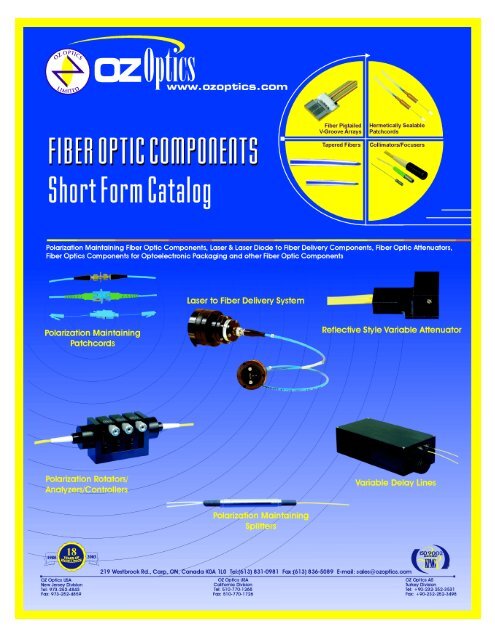
219 Westbrook Rd, Ottawa, ON, Canada, K0A 1L0 Toll Free: 1-800-361-5415 Tel:(613) 831-0981 Fax:(613) 836-5089 E-mail: sales@oz<strong>optic</strong>s.com<br />
ALL FIBER POLARIZATION CONTROLLER<br />
Features<br />
• No intrinsic loss<br />
• No backreflection<br />
• Compact size<br />
• Easy to use<br />
• Wavelength insensitive<br />
• Low cost<br />
Applications<br />
• Singlemode to Polarization Maintaining (PM) <strong>fiber</strong> launching<br />
• Polarization Dependent Loss (PDL) measurements<br />
• Launching into Polarization sensitive devices<br />
• Fiber lasers<br />
• Fiber interferometers<br />
Product Description<br />
Polarization controllers allow one to convert any input polarization<br />
to any desired output polarization. The device combines the<br />
compact size and ease of use of standard bulk <strong>optic</strong>s systems with<br />
low costs, low losses, and low backreflections.<br />
The controller works by applying pressure with an adjustable<br />
clamp. The pressure on the <strong>fiber</strong> causes a birefringence within<br />
the <strong>fiber</strong> core, causing the <strong>fiber</strong> to act as a fractional wave plate.<br />
Varying the pressure varies the delay between the fast and slow<br />
polarization components. The clamp is rotatable, allowing one to<br />
change the direction in which the stress is applied. This allows<br />
any output polarization to be achieved. The process is simple and<br />
quick. Output polarizations exceeding 30dB can be routinely<br />
achieved in seconds.<br />
The <strong>fiber</strong> polarization controller works with singlemode <strong>fiber</strong> of<br />
any wavelength. The controller does not work with multimode or<br />
Polarization Maintaining (PM) <strong>fiber</strong>. For multimode and PM <strong>fiber</strong><br />
OZ Optics still offers their standard series of polarization rotators<br />
and analyzers (refer to the Polarization Rotators/Controllers/<br />
Analyzers data sheet).<br />
All <strong>fiber</strong> polarization controllers are offered in three versions. The<br />
in-line polarization controller can be inserted onto a customer’s<br />
own singlemode <strong>fiber</strong>. It can be used with any wavelength<br />
singlemode <strong>fiber</strong>. The in-line version is designed to work with only<br />
250 micron and 400 micron jacketed <strong>fiber</strong>s. Second, a pigtailed<br />
version is also offered. This version is available with any size of<br />
cable or <strong>fiber</strong>, and with your choice of connectors. Finally, a<br />
connector receptacle style controller is available, using a short<br />
section of <strong>fiber</strong> terminated with female receptacles. For further<br />
information contact OZ Optics.<br />
In-Line Polarization<br />
Controller With Fiber<br />
Receptacle Style<br />
Polarization Controller<br />
In-Line Polarization<br />
Controller Without Fiber<br />
DTS0001 OZ Optics reserves the right to change any specifications without prior notice. 17-Nov-04<br />
1
Ordering Example For Standard Parts<br />
A university scientist is building a <strong>fiber</strong> interferometer and needs to manipulate the polarization of the light travelling through the <strong>fiber</strong>. He<br />
is using standard singlemode <strong>fiber</strong> for telecommunications wavelengths, and is using a 1480 nm source. To minimize reflections in his<br />
system he is using FC connectors with an APC finish. Based on this, a receptacle style controller will work in his application.<br />
Bar Code Part Number Description<br />
6324 HFPC-11-1300/1500-S-9/125-3A3A<br />
All Fiber Polarization Controller for 1300/1500 nm with 9/125 singlemode <strong>fiber</strong> and FC/APC<br />
receptacles on both ends.<br />
Questionnaire<br />
1. Which of the following options best describes your needs?<br />
a) I want to install and remove my own <strong>fiber</strong>.<br />
b) I want a specific <strong>fiber</strong> permanently installed.<br />
c) I want receptacles on either side to plug devices into.<br />
2. What wavelengths are you using?<br />
3. For pigtail style models, what should be the <strong>fiber</strong> length and cable type?<br />
4. For both pigtail and receptacle styles, what type of connector are you using?<br />
5. What is the intensity of the light travelling through the <strong>fiber</strong>?<br />
Ordering Information For Custom Parts<br />
Pigtail Version:<br />
PFPC-11-W-S-a/b-XY-JD-L<br />
Wavelength: Specify in nanometers<br />
(Example: 1550 for 1550 nm)<br />
Fiber core/cladding sizes, in microns<br />
9/125 for 1300/1550 nm SM <strong>fiber</strong>.<br />
See Table 1 of the Standard Tables for other<br />
standard <strong>fiber</strong> sizes<br />
Receptacle Version:<br />
HFPC-11-W-S-a/b-XY<br />
Fiber length, in meters, on each side of the device<br />
Example: To order 1 meter of <strong>fiber</strong> at the input and<br />
7 meters at the output, replace L with 1,7<br />
Fiber jacket type: 1=900 micron OD hytrel jacket<br />
3=3 mm OD Kevlar reinforced<br />
PVC cable<br />
See Table 7 of the Standard Tables for other jacket<br />
sizes<br />
Connector Code: 3S = Super NTT-FC/PC<br />
3U = Ultra NTT-FC/PC<br />
3A = Angled NTT-FC/PC<br />
8 = AT&T-ST<br />
SC = SC<br />
SCA = Angled SC<br />
See Table 6 of the Standard Tables for other<br />
connectors<br />
Wavelength: Specify in nanometers<br />
(Example: 1550 for 1550 nm)<br />
Fiber core/cladding sizes, in microns<br />
9/125 for 1300/1550 nm SM <strong>fiber</strong>.<br />
See Table 1 of the Standard Tables for other<br />
standard <strong>fiber</strong> sizes<br />
Connector Code: 3S = Super NTT-FC/PC<br />
3U = Ultra FC NTT-FC/PC<br />
3A = Angled NTT-FC/PC<br />
8 = AT&T-ST<br />
SC = SC<br />
SCA = Angled SC<br />
See Table 6 of the Standard Tables for other<br />
connectors<br />
Ordering Example For Custom Parts<br />
A <strong>fiber</strong> laser manufacturer wants to put a polarization controller in his system. His laser will operate at 1053 nm, so he needs singlemode<br />
<strong>fiber</strong> for that wavelength. He needs 10 meters of <strong>fiber</strong> installed in the device, five meters per side. For strength and safety, he is using<br />
3 mm OD cabling. He wants FC/APC connectors on both ends.<br />
Part Number<br />
PFPC-11-980-S-6/125-3A3A-3-5<br />
Description<br />
All Fiber Polarization Controller with 5 meter long 3 mm OD Kevlar reinforced PVC cabled 980 nm<br />
6/125 singlemode <strong>fiber</strong> pigtails with FC/APC connectors on both ends.<br />
3
219 Westbrook Rd, Ottawa, ON, Canada, K0A 1L0 Toll Free: 1-800-361-5415 Tel:(613) 831-0981 Fax:(613) 836-5089 E-mail: sales@oz<strong>optic</strong>s.com<br />
Features:<br />
• High output power from 13 dBm (20mW) to 27 dBm (500mW)<br />
• Wide spectral bandwidth<br />
• Covers C-band, L-band, or both<br />
• High stability<br />
• Multi-output option-up to 4 ports<br />
• Un-polarized output light<br />
• Optional RS232 or USB interface<br />
• High performance-to-cost ratio<br />
• Optional built-in attenuator and <strong>optic</strong>al power monitor<br />
• Custom design flexibility<br />
ASE BROADBAND LIGHT SOURCE<br />
Preliminary<br />
Applications:<br />
• Optical component testing<br />
• Telecom system compliance testing<br />
• EDFA gain spectrum measurements<br />
• Optical <strong>fiber</strong> sensors and sensing systems<br />
• WDM by spectral slicing<br />
• Biomedical imaging<br />
• Coherent communication systems<br />
Erbium-doped Fiber ASE Broadband Light Source<br />
Product Description:<br />
An ASE (Amplified Spontaneous Emission) broadband low<br />
coherence light source is an ideal instrument for <strong>optic</strong>al component<br />
spectral measurement and system compliance testing in<br />
manufacturing and R&D environments. The new generation of ASE<br />
sources have no high frequency ripples, which makes them very<br />
useful for sensor interrogation applications.<br />
Sources are available to cover the C-band, L-band, or both the C &<br />
L bands together. These are available with either a flattened spectral<br />
output for demanding applications, or a non-flattened response for<br />
less demanding or cost-sensitive applications. A range of output<br />
powers are available.<br />
The output light is accessed via a female <strong>fiber</strong> connector receptacle<br />
on the front panel. A variety of standard connector types are<br />
available. Custom connectors can also be accommodated. Built-in<br />
splitters can also be provided to give multiple outputs without the<br />
cost of purchasing multiple sources.<br />
The basic version of the source has a simple ON/OFF operation. A<br />
built-in attenuator is available as an option, for users who need to be<br />
able to vary the output power. A built-in microprocessor can be<br />
included for applications that require the source or optional<br />
attenuator to operate under computer control. Either RS-232 or USB<br />
interfaces are offered.<br />
DTS0106 OZ Optics reserves the right to change any specifications without prior notice. 22-Mar-05<br />
1
Questionnaire<br />
1. What is the required power level?<br />
2. What range of wavelengths do you need?<br />
3. Would you like more than one <strong>optic</strong>al output? If yes, how many?<br />
4. Do you need to be able to control the <strong>optic</strong>al power?<br />
5. Do you need to have the source controlled by a computer? If yes, with what control interface?<br />
6. Do you need a flattened spectral response?<br />
7. What is your preferred connector interface?<br />
8. What sort of package style do you prefer?<br />
Description<br />
ASE Broadband Source<br />
Part Number<br />
ASE-N-PP-B-S-F-X-O-I<br />
N<br />
PP<br />
B<br />
S<br />
Number of Output Ports.<br />
Specify 1, 2 or 4. The specified output<br />
power is divided equally amongst the<br />
output ports.<br />
Output Power in dBm:<br />
Example – specify 13 for 13 dBm, 27<br />
for 27 dBm. Power should be within the<br />
range of 13 to 27 dBm.<br />
Wavelength band:<br />
C = C band<br />
L = L band<br />
D= C & L bands<br />
Package style:<br />
1 = Bench top<br />
2 = Rack mountable<br />
3 = OEM module<br />
4 = Gain Block - No electronics<br />
provided, user must provide pump<br />
drivers<br />
9 = Custom<br />
I<br />
O<br />
X<br />
Control interface:<br />
R = RS232<br />
U = USB<br />
X = Not Applicable - ie. gain block<br />
version or basic version<br />
Options<br />
A = Built-in attenuator with<br />
microprocessor control<br />
B = Basic version<br />
M = Microprocessor controlled<br />
Receptacle style:<br />
3 = Standard flat, Super, or Ultra FC/PC<br />
3A = Angled FC/PC<br />
8 = AT&T-ST<br />
SC = SC<br />
SCA = Angled SC<br />
LC = LC<br />
MU = MU<br />
F<br />
Flatness:<br />
N = Non-flattened<br />
F = Flattened<br />
3
Features:<br />
219 Westbrook Rd, Ottawa, ON, Canada, K0A 1L0 Toll Free: 1-800-361-5415 Tel:(613) 831-0981 Fax:(613) 836-5089 E-mail: sales@oz<strong>optic</strong>s.com<br />
PRELIMINARY<br />
• Sensitivity to -70 dB<br />
• Built-in RS-232 communications port<br />
• Wide range of available wavelengths<br />
• Built-in source<br />
• Dual wavelength source available<br />
• Rugged and compact design<br />
• High resolution<br />
• Optional insertion loss measurement capability<br />
BACKREFLECTION METER<br />
Applications:<br />
• Backreflection measurement of components<br />
• Insertion loss measurement<br />
• End-to-end loss measurement<br />
• Quality control<br />
• New Product development<br />
• Component or system troubleshooting<br />
• Network installation<br />
Fiber Optic Backreflection Meter<br />
Product Description:<br />
The OZ Optics Limited BM-100 and BM-200 Backreflection Meters measure the total accumulated <strong>optic</strong>al return loss that is reflected back<br />
through a device or <strong>fiber</strong> under test. The measured reflections are caused by Rayleigh scattering, sudden changes in the refractive index<br />
within the device under test (DUT), or from connector ends.<br />
The Backreflection Meter is configured with an FC/APC connector on the output port, to minimize unwanted reflections. The meter has either<br />
one or two built-in laser diodes for return loss measurement at specific wavelengths. An optional detector can be added to the unit for insertion<br />
loss measurements. Reference patchcords for calibration are available. Adaptor patchcords are also available, to allow the meter to be used<br />
with devices having different connectors.<br />
The BM-100 and BM-200 Backreflection Meters can be operated remotely via the built-in RS-232 interface. An optional GPIB to RS-232<br />
converter is also available. A universal AC/DC power supply, with a North American-standard power cord, is included with all units. Other types<br />
of power cords can be purchased separately.<br />
DTS0002 OZ Optics reserves the right to change any specifications without prior notice. 11/14/02 1
Ordering Examples For Standard Parts:<br />
A European <strong>fiber</strong> <strong>optic</strong> manufacturer must measure the backreflection and the insertion loss of singlemode and polarization-maintaining jumpers, at<br />
1550 nm and at 1310 nm. The manufacturer needs to order the following parts:<br />
Bar Code Part Number Description<br />
14726 BM-200-3A-1310/1550-9/125-S-IL Singlemode Fiber Optic Backreflection Meter, with dual 1310 and 1550 nm<br />
built-in sources and insertion loss measurement capability.<br />
10229 SMJ-3A1-1300/1550-9/125-3-1 Reference patchcord, FC/APC to flat-polished ferrule, 9/125 micron<br />
singlemode 1300/1550 nm <strong>fiber</strong>, 3 mm OD PVC jacket, 1 m long.<br />
8131 SMJ-3A3U-1300/1550-9/125-3-2 Hybrid patchcord, FC/APC to FC/UPC, 9/125 micron singlemode 1300/1550<br />
nm <strong>fiber</strong>, 3 mm OD PVC jacket, 2 m long.<br />
2737 POWER CORD - EUROPE European power cord.<br />
Ordering Information For Custom Parts:<br />
Although we strongly recommend the purchase of our standard products, OZ Optics also welcomes the opportunity to provide customdesigned<br />
products to meet your application requirements. There can be a difference in the pricing for a custom-designed device or part<br />
compared to our standard parts list. Please consider the following points when reviewing your quotation:<br />
• Additional time is required to prepare a comprehensive quotation.<br />
• Lead times are usually longer than normal.<br />
• Non-recurring engineering (NRE) charges and lot charges may apply.<br />
• A five piece minimum order is necessary.<br />
These points will be carefully explained in your quotation, so you can make a well-informed decision.<br />
Questionnaire For Custom Parts:<br />
1. What is your application?<br />
2. What wavelengths do you plan to use?<br />
3. What connector receptacle type do you need?<br />
4. What <strong>fiber</strong> type are you using?<br />
5. What is the minimum backreflection you want to measure?<br />
6. Do you want to measure insertion losses?<br />
7. Do you want a single wavelength or dual wavelength source?<br />
Backreflection Meter:<br />
BM-A-X-W-a/b - F - BL(-IL)<br />
A =Source type:<br />
100: Single wavelength source<br />
200: Dual wavelength source<br />
X = Connector Code :<br />
3= Standard, Super, Ultra NTT-FC/PC<br />
receptacle<br />
3A= Angled NTT- FC/PC<br />
SC=SC<br />
SCA=Angled SC<br />
8= AT&T-ST<br />
IL = Add -IL to the end of the part number for<br />
insertion loss measurement capability.<br />
BL = Backreflection range. If not specified,<br />
then a range of 70dB is assumed for<br />
singlemode <strong>fiber</strong> and 30dB for multimode<br />
<strong>fiber</strong>.<br />
F = Fiber type<br />
S: Singlemode<br />
M: Multimode<br />
W = Wavelength in nm:<br />
850, 980, 1310,1480,1550,1625 or<br />
W 1 /W 2 for dual source, in nm:<br />
1310/1550, 1550/1625, 1480/1550<br />
a/b = Fiber core/cladding sizes, in µm<br />
9/125 for 1300/1550nm SM <strong>fiber</strong>.<br />
Notes:<br />
1. For the multimode backreflection meter, the minimum measureable backreflection is 30 dB. Multimode backreflection meters are<br />
configured with LED sources.<br />
2. For singlemode backreflection meters, the minimum measureable backreflection measurement is 70 dB, with angled FC/PC connectors, at<br />
wavelengths of 1310 nm, or higher. 3
219 Westbrook Rd, Ottawa, ON, Canada, K0A 1L0 Toll Free: 1-800-361-5415 Tel:(613) 831-0981 Fax:(613) 836-5089 E-mail: sales@oz<strong>optic</strong>s.com<br />
BARE FIBER ADAPTER<br />
Bare <strong>fiber</strong> preparation<br />
Bare <strong>fiber</strong> adapters provide a simple and effective way to use<br />
unterminated <strong>fiber</strong>s with commercial receptacles. Simply strip and<br />
cleave your <strong>fiber</strong> and insert into the bare <strong>fiber</strong> adapter. Broken<br />
<strong>fiber</strong>s are easily removed with piano wire, allowing hundreds of<br />
insertions. They are recommended for power meter hook-ups,<br />
temporary system repairs or wherever a quick <strong>fiber</strong> connection is<br />
required. Standard adapters accommodate 81 micron, 125<br />
micron or 140 micron cladding <strong>fiber</strong>s with a typical insertion loss<br />
of less than 1dB.<br />
OPERATING INSTRUCTIONS<br />
Note: When using alcohol and acetone, carefully follow all<br />
safety, health and disposal information given on the<br />
container label, and on any material safety data sheets.<br />
1. If you are using the bare <strong>fiber</strong> adapter with uncabled<br />
<strong>fiber</strong>, proceed to step 2. If you are using cabled <strong>fiber</strong>s, strip at<br />
least 3 inches of the cable's outer jacket and cut away the<br />
exposed strength members (usually Kevlar <strong>fiber</strong>s near the<br />
stripped edge).<br />
ORDERING INFORMATION:<br />
Part Number<br />
BARE-03-b<br />
BARE-08-b<br />
Description<br />
Bare <strong>fiber</strong> adapter for FC connectors.<br />
Bare <strong>fiber</strong> adapter for ST connectors<br />
2. Strip a sufficient amount of the buffer to allow for <strong>fiber</strong> cleaving.<br />
The length of buffer stripped from the <strong>fiber</strong> will depend on the<br />
type of cleaving tool used. (Usually 1" to 2" is adequate.)<br />
3. Cleave the <strong>fiber</strong>, leaving approximately 1/2" to 5/8" of exposed<br />
<strong>fiber</strong>. (See the illustration above).<br />
4. Clean the exposed cladding with acetone and/or isopropyl<br />
alcohol (reagent grade).<br />
5. Depress the spring-loaded buffer clamping mechanism and<br />
insert the cleaved <strong>fiber</strong> into the acceptance hole. Push the<br />
<strong>fiber</strong> through until the cleaved <strong>fiber</strong> end is flush with the<br />
ceramic ferrule end face. At this point release the buffer<br />
clamping mechanism, to hold the <strong>fiber</strong> in place. Inspect the<br />
end face with an eye loop and if necessary, adjust the <strong>fiber</strong><br />
until it is flush.<br />
6. Clean the surface of the ceramic ferrule with a lint-free, alcohol<br />
dampened cloth and blow dry with compressed air.<br />
7. The <strong>fiber</strong> is now ready for use. Insert the adapter into the<br />
<strong>optic</strong>al test equipment's coupler.<br />
Where: b is the ferrule hole size, in microns Standard sizes are 81 microns, 127 microns and 144 microns.<br />
Hole size tolerance is +1/-0 microns<br />
Contact OZ Optics for bare <strong>fiber</strong> adapters for other adapter types, and other hole diameters.<br />
ORDERING EXAMPLE: An FC style bare <strong>fiber</strong> adapter is needed for use with 127 micron cladded <strong>fiber</strong>s. OZ Optics part<br />
number: BARE-03-127.<br />
09/99 OZ Optics reserves the right to change any specifications without prior notice.
219 Westbrook Rd, Ottawa, ON, Canada, K0A 1L0 Toll Free: 1-800-361-5415 Tel:(613) 831-0981 Fax:(613) 836-5089 E-mail: sales@oz<strong>optic</strong>s.com<br />
BEAM SPLITTERS/COMBINERS<br />
Features<br />
• High power handling<br />
• High extinction ratio<br />
• Highly modular and flexible design<br />
• Wide wavelength range<br />
• Bi-directional<br />
• Broadband performance<br />
• Custom designs welcomed<br />
• Mode independent behavior in multimode <strong>fiber</strong> applications.<br />
Applications<br />
• EDFA amplifier<br />
• Raman amplifier combiner<br />
• Polarization mode dispersion compensation<br />
• Polarization extinction ratio measurements<br />
• Fiber <strong>optic</strong> sensors<br />
• Coherent communication systems<br />
• Return loss measurement<br />
Product Description<br />
Fiber <strong>optic</strong> beam splitters are used to divide light from one <strong>fiber</strong> into two<br />
or more <strong>fiber</strong>s. Light from an input <strong>fiber</strong> is first collimated, then sent<br />
through a beam splitting <strong>optic</strong> to divide it into two. The resultant output<br />
beams are then focused back into the output <strong>fiber</strong>s. Both 1XN and 2XN<br />
splitters can be constructed in this fashion with both low return losses<br />
and low insertion losses. This design is extremely flexible, allowing one<br />
to use different <strong>fiber</strong> types on different ports, and different beam splitter<br />
<strong>optic</strong>s inside. Splitters can also be made with either <strong>fiber</strong>s permanently<br />
attached to each port (pigtail style) or with receptacles on each port that<br />
one can plug your <strong>fiber</strong> into (receptacle style). We can also build source<br />
to <strong>fiber</strong> couplers with built-in beamsplitters for either laser or laser diode<br />
sources. Contact OZ for details.<br />
Please note that we strongly recommend using pigtail style devices<br />
whenever possible. Mechanical tolerances on connectors and<br />
receptacles mean receptacle style devices suffer from higher losses and<br />
poorer polarization extinction ratios than pigtail style devices. This is<br />
especially true for singlemode and polarization maintaining <strong>fiber</strong><br />
devices.<br />
If size is a concern, we recommend that you consider our miniature line<br />
of splitters. Please refer to our data sheet titled Miniature Inline<br />
Polarization Maintaining Splitters/Taps/Combiners.<br />
The two most common types of splitters offered are polarizing beam<br />
splitters and polarization maintaining beam splitters. Their operating<br />
principles are as follows:<br />
Polarization Maintaining Splitters: These splitters use a partially<br />
reflecting mirror to transmit a portion of the light from the input <strong>fiber</strong> to<br />
the main output <strong>fiber</strong>, and reflect the remainder of the light to the second<br />
output <strong>fiber</strong>. All ports made using polarization maintaining <strong>fiber</strong> are<br />
Pigtail Style One-by-two Splitter<br />
Pigtail Style Two-by-two Splitter<br />
Laser To Fiber Coupler<br />
With Built-in Beam Splitter<br />
Laser Diode<br />
Polarization Beam Combiner<br />
DTS0095 OZ Optics reserves the right to change any specifications without prior notice. 03-Mar-05<br />
1
aligned so that polarized light aligned parallel to the stress rods on<br />
the input <strong>fiber</strong> emerges from the output <strong>fiber</strong>s in the same manner,<br />
maintaining the polarization state to a high degree.<br />
Polarization maintaining splitters use a multi-layer coating to split the<br />
light by a specific ratio regardless of the incoming polarization.<br />
Because of the nature of these coatings, their behavior will vary<br />
somewhat with respect to wavelength, and so are recommended for<br />
an operating wavelength range of about ±10nm. Broadband beam<br />
splitters are offered, but with greater variation in the split ratio with<br />
respect to input polarization.<br />
Splitters that only split off a small portion of the input light are<br />
commonly known as taps. These splitters are often used for power<br />
monitoring applications. The small signal, typically between one and<br />
ten percent, is sent to a monitoring photodiode, while the majority of<br />
the signal goes on to the main destination. For a very low cost<br />
alternative configuration, combining the functions of a tap and<br />
monitor photodiode in a single unit, we invite you to review our Inline<br />
Optical Taps and Monitors data sheet.<br />
Polarizing Splitters: Polarizing Beam Splitters split incoming light<br />
into two orthogonal states. They can also be used to combine the<br />
light from two <strong>fiber</strong>s into a single output <strong>fiber</strong>. When used as a beam<br />
combiner, each input signal will transmit along a different output<br />
polarization axis. It is important when using these splitters with<br />
polarization maintaining <strong>fiber</strong> that one understands how the<br />
polarization axes are aligned on each port. Figure 1 one shows the<br />
standard configuration. With this configuration, the following<br />
behavior will be observed:<br />
1) Light launched along the slow axis of input port T will be<br />
transmitted along the slow axis of output port 1<br />
2) Light launched along the fast axis of input port T will be<br />
transmitted along the slow axis of output port 2<br />
3) Light launched along the slow axis of input port R will be<br />
transmitted along the fast axis of output port 1<br />
4) Light launched along the fast axis of input port R will be<br />
transmitted along the fast axis of output port 2<br />
This configuration can be changed based on a customer’s<br />
requirements.<br />
Please note that with polarizing splitters there are two<br />
considerations: The ability of the splitter to prevent polarized light<br />
intended for port 1 from reaching port 2 or vice versa (polarization<br />
crosstalk), and the output polarization extinction ratio of the light<br />
emerging from polarization maintaining <strong>fiber</strong>s attached to each port.<br />
The crosstalk level will always be equal to or greater than the<br />
polarization extinction ratio. For example, a splitter can be produced<br />
with a high cross talk ratio, but if the output <strong>fiber</strong>s have mediocre<br />
performance, then the output polarization extinction ratio would be<br />
low. Please be sure to specify both of these values if your system<br />
has special requirements.<br />
Input<br />
Port R<br />
PORT R<br />
Two 4-40 Tapped holes,<br />
0.50 inches apart,<br />
0.34 inches deep<br />
(On the bottom) 0.39<br />
(TYP)<br />
Input<br />
Port T<br />
Output<br />
Port 1<br />
PORT T<br />
0.87<br />
PORT 1<br />
Output<br />
Port 2<br />
PORT 2<br />
0.87<br />
Figure 1: Standard orientation of polarization maintaining<br />
<strong>fiber</strong>s on polarizing beamsplitters<br />
Figure 2: Dimensions of standard two-by-two splitter<br />
2
Description<br />
Pigtail Style<br />
One-by-two Splitter<br />
Pigtail Style<br />
Two-by-two Splitter<br />
Part Number<br />
FOBS-12P-111-a/b-ABC-W-S/R-LB-XYZ-JD-L<br />
FOBS-22P-1111-a/b-ADBC-W-S/R-LB-XTYZ-JD-L<br />
a/b = Fiber core/cladding sizes in microns<br />
9/125 for 1300/1550 nm singlemode <strong>fiber</strong>.<br />
8/125 for 1550 nm PM <strong>fiber</strong><br />
7/125 for 1300 nm PM <strong>fiber</strong><br />
See tables 1 to 5 of the Standard Tables<br />
data sheet for other standard <strong>fiber</strong> sizes<br />
A,D, = Fiber Types on each port<br />
B,C (Input T, Input R, Output 1 and Output 2)<br />
M = Multimode<br />
S = Singlemode<br />
P = Polarization Maintaining<br />
W =<br />
Wavelength: Specify in nanometers<br />
(Example: 1550 for 1550 nm)<br />
S/R = Splitting ratio: 50/50 to 95/5<br />
50/50 Standard<br />
Use PBS for polarizing splitters<br />
L =<br />
JD =<br />
LB =<br />
Fiber length, in meters<br />
Fiber jacket type<br />
0.25 = 250 micron OD acrylate coating<br />
1 = 900 micron OD hytrel jacket<br />
3 = 3 mm OD Kevlar reinforced PVC cable<br />
X,T, = Connector codes for each port<br />
Y,Z 3S = Super NTT-FC/PC<br />
3U = Ultra NTT-FC/PC<br />
3A = Angled NTT-FC/PC<br />
LC = LC<br />
SC = SC<br />
SCA = Angled SC<br />
See Table 6 of the Standard Tables data sheet<br />
for other connectors<br />
Backreflection level:<br />
30, 40, 50, or 60 dB<br />
50, 60 dB are standard for 1300 nm to<br />
1550 nm only<br />
40 dB standard for other wavelengths<br />
30 dB is standard for multimode<br />
Note: Add “-ER=25” or “-ER=30” to the end of the part number for products with output polarization greater than 25 dB and 30 dB, respectively.<br />
Description<br />
Receptacle Style<br />
One-by-two Splitter<br />
Receptacle Style<br />
Two-by-two Splitter<br />
Part Number<br />
FOBS-12-XYZ-ABC-W-S/R<br />
FOBS-22-XTYZ-ADBC-W-S/R<br />
X,T, = Connector codes for each port<br />
Y,Z 3 = FC, Super FC/PC and Ultra FC/PC<br />
3AF = Angled Flat NTT-FC<br />
SC = SC<br />
See Table 6 of the Standard Tables data sheet for<br />
other connectors<br />
S/R = Splitting ratio: 50/50 to 95/5<br />
50/50 Standard<br />
Use PBS for polarizing splitters<br />
W =<br />
Wavelength: Specify in nanometers<br />
(Example: 1550 for 1550 nm)<br />
A,D, = Fiber Types on each port<br />
B,C (Input T, Input R, Output 1and Output 2)<br />
M = Multimode<br />
S = Singlemode<br />
P = Polarization Maintaining<br />
5
Description<br />
Pigtail Style Laser Diode<br />
to Fiber Splitter<br />
Pigtail Style Laser<br />
to Fiber Splitter<br />
Part Number<br />
LDBS-12P-a/b-AB-W-S/R-LB-XY-JD-L-C<br />
ULBS-12P-a/b-AB-W-S/R-f-LH-LB-XY-JD-L<br />
a/b = Fiber core/cladding sizes in microns<br />
9/125 for 1300/1550 nm singlemode <strong>fiber</strong>.<br />
8/125 for 1550 nm PM <strong>fiber</strong><br />
7/125 for 1300 nm PM <strong>fiber</strong><br />
See tables 1 to 5 of the Standard Tables<br />
data sheet for other standard <strong>fiber</strong> sizes<br />
A,B = Fiber Types on each port<br />
(Output 1, Output 2)<br />
M = Multimode<br />
S = Singlemode<br />
P = Polarization Maintaining<br />
W =<br />
Wavelength: Specify in nanometers<br />
(Example: 1550 for 1550 nm)<br />
S/R = Splitting ratio: 50/50 to 95/5<br />
50/50 Standard<br />
Use PBS for polarizing splitters<br />
f = Lens ID: See Lens Selection Guide 3<br />
for Non-Contact couplers with<br />
receptacles in the Laser to Fiber<br />
Coupler Application Notes<br />
LH = Laser Head Adapter<br />
1 for 1” -32TPI Male Threaded Adapter<br />
2 for Disk Adapter with 4 holes on 1”<br />
square<br />
11 for Post Mount Adapter<br />
See Table 8 of the Standard Tables data sheet<br />
for other connectors<br />
C = Coupling Efficiency 1 :<br />
30 = 30%<br />
45 = 45%<br />
75 = 75%<br />
L =<br />
JD =<br />
LB =<br />
Fiber length, in meters<br />
Fiber jacket type<br />
0.25 = 250 micron OD acrylate coating<br />
1 = 900 micron OD hytrel jacket<br />
3 = 3 mm OD Kevlar reinforced PVC cable<br />
X,Y = Connector codes for each port<br />
3S = Super NTT-FC/PC<br />
3U = Ultra NTT-FC/PC<br />
3A = Angled NTT-FC/PC<br />
LC = LC<br />
SC = SC<br />
SCA = Angled SC<br />
See Table 6 of the Standard Tables data sheet<br />
for other connectors<br />
Backreflection level:<br />
30, 40, 50, or 60 dB<br />
50, 60 dB are standard for 1300 nm to<br />
1550 nm only<br />
40 dB standard for other wavelengths<br />
30 dB is standard for multimode<br />
1 Note that due to variations in the <strong>optic</strong>al characteristics of the laser diode being used, not all coupling efficiencies are available for every laser diode for every<br />
<strong>fiber</strong> type.<br />
Description<br />
Receptacle Style Laser Diode<br />
to Fiber Splitter<br />
Receptacle Style Laser<br />
to Fiber Splitter<br />
Part Number<br />
LDBS-1XY-AB-W-S/R-C<br />
ULBS-1XY-AB-W-S/R-f-LH<br />
X,Y = Connector codes for each port<br />
3 = FC, Super FC/PC and Ultra FC/PC<br />
3AF = Angled Flat NTT-FC<br />
SC = SC<br />
See Table 6 of the Standard Tables data sheet for<br />
other connectors<br />
A,B = Fiber Types on each port<br />
(Output 1, Output 2)<br />
M = Multimode<br />
S = Singlemode<br />
P = Polarization Maintaining<br />
W =<br />
Wavelength: Specify in nanometers<br />
(Example: 1550 for 1550 nm)<br />
S/R = Splitting ratio: 50/50 to 95/5<br />
50/50 Standard<br />
Use PBS for polarizing splitters<br />
C = Coupling Efficiency 1 :<br />
30 = 30%<br />
45 = 45%<br />
75 = 75%<br />
LH = Laser Head Adapter<br />
1 for 1” -32TPI Male Threaded Adapter<br />
2 for Disk Adapter with 4 holes on 1”<br />
square<br />
11 for Post Mount Adapter<br />
See Table 8 of the Standard Tables data sheet for<br />
other connectors<br />
f = Lens ID: See Lens Selection Guide 3<br />
for Non-Contact couplers with<br />
receptacles in the Laser to Fiber<br />
Coupler Application Notes<br />
1 Note that due to variations in the <strong>optic</strong>al characteristics of the laser diode being used, not all coupling efficiencies are available for every laser diode for every<br />
<strong>fiber</strong> type.<br />
6
219 Westbrook Rd, Ottawa, ON, Canada, K0A 1L0 Toll Free: 1-800-361-5415 Tel:(613) 831-0981 Fax:(613) 836-5089 E-mail: sales@oz<strong>optic</strong>s.com<br />
COLLIMATORS AND FOCUSERS – RECEPTACLE STYLE<br />
FEATURES:<br />
• High power handling<br />
• Rugged and compact design<br />
• Low insertion loss<br />
• Wide wavelength range<br />
• Wide range of beam diameters<br />
• GRIN, aspheric, achromatic, plano-convex, and<br />
biconvex lenses available<br />
• Singlemode, multimode, and polarization maintaining<br />
<strong>fiber</strong> versions<br />
• Diffraction limited <strong>optic</strong>s<br />
• LOW COST!<br />
PRELIMINARY<br />
APPLICATIONS:<br />
• Fiber <strong>optic</strong> device packaging, including WDM’s<br />
Splitters, and integrated <strong>optic</strong>s<br />
• Source to <strong>fiber</strong> coupling<br />
• Fiber to detector coupling<br />
SPECIFICATIONS:<br />
• Available Wavelengths: 180nm - 2000nm<br />
• Polarization<br />
Extinction ratios:<br />
20, 25, or 30dB<br />
• Beam Diameters: 0.2 to 22mm<br />
• Spot size: As small as
For <strong>fiber</strong> focusers, the exact calculation of the spot diameter (SD),<br />
magnification factor (M), and working distance (WD) is more<br />
difficult and depends on the properties of the lenses being used.<br />
As a first approximation, one can calculate the desired focuser<br />
characteristics using the geometric <strong>optic</strong>s lens formulae:<br />
FIBER COLLIMATOR<br />
FIBER<br />
LENS<br />
DA/2<br />
FIBER FOCUSER<br />
FIBER<br />
LENS<br />
1<br />
+<br />
1 1 i<br />
i o<br />
= M<br />
f<br />
= -<br />
o<br />
SD = M × a WD =~ i<br />
Where o, i are the object and image distances respectively. Use<br />
the above formulae to determine what focal lens you require.<br />
Standard focal lengths and lenses are listed in the Standard<br />
Tables data sheet.<br />
Specifications:<br />
a<br />
f<br />
NA<br />
BD = 2×f×NA<br />
DA = a/f<br />
DA/2<br />
BD<br />
Figure 2: Operating Principle<br />
a<br />
o<br />
1/i + 1/o = 1/f<br />
M = -i/o, SD = M×a<br />
Note: The following specifications are typical values, and may vary, depending on the exact model selected. Contact OZ for detailed<br />
specifications for your exact model.<br />
Temperature Range: Operating: -15°C to 55°C with 0.2dB deviation in loss.<br />
Storage: -45°C to +75°C with less than 0.05dB residual loss.<br />
Vibration and Shock Test: Vibration tests were performed, consisting of a 0.05 inch peak to peak displacement, sweeping from 10 to 55 Hz<br />
over 15 minutes dwell at worst resonance of 55 Hz (.02g). Each device was tested for twenty-five minutes per axis<br />
for a total of 75 minutes of vibration. Tests were conducted in each of the three major axes of the test unit. Shock<br />
tests consisting on 100g, 11 msec duration half-sine shocks, three times on each face for a total of 18 shocks,<br />
were also performed. Coupling loss deviation was 0.05dB with no hysteresis.<br />
Power Handling: GRIN lenses: Up to 1 Watt. Aspheric lenses:Up to 10 Watts<br />
Achromat lenses: 5 to 10 Watts<br />
Plano- and Bi-convex lenses: Up to 100 Watts<br />
Available Wavelengths: GRIN lenses: 450-1700nm Aspheric lenses:390-2000nm<br />
Achromat lenses: 400/700nm and 700-1600nm Plano- and Bi-convex lenses: 180-2000nm<br />
Polarization Extinction Ratios:<br />
Dimensions:<br />
Typically >30dB for Aspheric lenses, >20dB for others.<br />
The dimensions given below are representative of typical products manufactured by OZ Optics. Actual dimensions will depend on the actual<br />
model ordered. In particular, the lengths of focusers may vary considerably from the lengths of a collimator for a given lens. The choice of<br />
receptacle will also affect the overall length. However, unless noted otherwise the dimensions for the clear holes, tapped holes and outer<br />
diameters of the flanges are accurate, and do not vary within product families regardless of which specific model collimator or focuser is<br />
purchased.<br />
The lens codes for which each version is designed for is listed below each drawing. Use the lens code to find the dimensions for your assembly.<br />
i<br />
SD<br />
0.200<br />
0.313<br />
0.515<br />
0.320 0.350<br />
0.100<br />
0.260<br />
0.240<br />
0.433<br />
0.463<br />
0.582<br />
0.727<br />
1.343<br />
0.645<br />
0.675<br />
0.784<br />
0.929<br />
1.545<br />
Three 0-80 tapped holes<br />
120° apart on a 1.125"<br />
diameter bolt circle<br />
2AS<br />
3.9AS<br />
2.7AS<br />
3.5AC<br />
6AC<br />
6.2AS<br />
10AC<br />
5BQ<br />
10BQ 25AC Hole<br />
Pattern<br />
HPUCO-23 Dimensions<br />
Note: All units are in inches<br />
Three Ø0.096 thru holes<br />
120° apart on a 1.125"<br />
diameter bolt circle<br />
ø0.791<br />
ø0.590<br />
ø0.472<br />
0.240<br />
0.353<br />
0.555<br />
Three 0-80 tapped holes<br />
120° apart on a 1.125"<br />
diameter bolt circle<br />
2.19<br />
1.97<br />
2.38<br />
3.5AC<br />
4.5AC<br />
6AC<br />
2AS<br />
2.7AS<br />
Hole<br />
Pattern<br />
3.5AC 2AS 11AS<br />
4.5AC 2.7AS 13.9AS<br />
6AC 3.9AS 18AC<br />
10AC 6.2AS 5BQ<br />
16AC 8AS<br />
HPUCO-33 Dimensions<br />
HPUCO-83 Dimensions<br />
2
Ordering Information For Custom Parts:<br />
OZ Optics welcomes the opportunity to provide custom designed products to meet your application needs. As with most manufacturers,<br />
customized products do take additional effort so please expect some differences in the pricing compared to our standard parts list. In<br />
particular, we will need additional time to prepare a comprehensive quotation, and lead times will be longer than normal. These points will be<br />
carefully explained in your quotation, so your decision will be as well-informed as possible. We strongly recommend buying our standard<br />
products.<br />
Questionairre For Custom Parts<br />
1. Do you require a <strong>fiber</strong> <strong>optic</strong> collimator, or a <strong>fiber</strong> <strong>optic</strong> focuser instead?<br />
2a. For <strong>fiber</strong> collimator users only:<br />
What is the desired collimated beam diameter (in mm)?<br />
What is the desired collimated divergence angle (mRad)?<br />
2b. For <strong>fiber</strong> focuser users only:<br />
What is the desired spot diameter (in microns)?<br />
What is the desired working distance (in mm)?<br />
3. What is your operating wavelength range, in nanometers?<br />
4. Will you be using singlemode, multimode, or polarization maintaining <strong>fiber</strong>s?<br />
5. What type of connector is on your <strong>fiber</strong>?<br />
6. What is the output power through your <strong>fiber</strong>?<br />
7. What is the desired flange size? 33mm, 20mm, 12mm, 11mm, or something else?<br />
Description<br />
Non-Contact Receptacle Style Collimator:<br />
Part Number<br />
HPUCO-AX-W-F-f<br />
A = Collimator Size<br />
2 for 33mm OD flange<br />
3 for 20mm OD flange<br />
8 for 12mm diameter by 50mm long housing<br />
T for 11mm diameter housing<br />
X = Connector code:<br />
3 = FC (Compatible with Flat, Super PC<br />
and Ultra PC finishes<br />
3A = Angled NTT-FC/PC<br />
3AF = Angled Flat FC<br />
8 = AT & T-ST<br />
SC = SC<br />
See table 6 of the OZ Standard Tables data<br />
sheet for other connectors.<br />
f = Lens focal length and type:<br />
See Tables 9 to 12 of the standard tables data<br />
sheet for a list of available lenses and the<br />
collimator housings they fit.<br />
F = Fiber Type: M = Multimode<br />
S = Singlemode<br />
P = Polarization maintaining<br />
W = Wavelength in nm:<br />
(Example: Specify 633 for 633nm)<br />
For achromat lenses at visible<br />
wavelengths specify 400/700<br />
Description<br />
Non-Contact Receptacle Style Focuser:<br />
Part Number<br />
HPUFO-AX-W-F-M-WD-f<br />
A = Collimator Size<br />
2 for 33mm OD flange<br />
3 for 20mm OD flange<br />
8 for 12mm diameter by 50mm long housing<br />
T for 11mm diameter housing<br />
X = Connector code:<br />
3 = FC (Compatible with Flat, Super PC<br />
and Ultra PC finishes<br />
3A = Angled NTT-FC/PC<br />
3AF = Angled Flat FC<br />
8 = AT & T-ST<br />
SC = SC<br />
See table 6 of the OZ Standard Tables data<br />
sheet for other connectors.<br />
f = Lens focal length and type:<br />
See Tables 9 to 12 of the standard tables data<br />
sheet for a list of available lenses and the<br />
collimator housings they fit.<br />
WD = Working Distance, in mm<br />
M = Magnification Factor<br />
F = Fiber Type: M = Multimode<br />
S = Singlemode<br />
P = Polarization maintaining<br />
W = Wavelength in nm:<br />
(Example: Specify 633 for 633nm)<br />
For achromat lenses at visible<br />
wavelengths specify 400/700<br />
5
219 Westbrook Rd, Ottawa, ON, Canada, K0A 1L0 Toll Free: 1-800-361-5415 Tel:(613) 831-0981 Fax:(613) 836-5089 E-mail: sales@oz<strong>optic</strong>s.com<br />
COLLIMATORS AND FOCUSERS – PIGTAIL STYLE<br />
FEATURES:<br />
• High power handling<br />
• Rugged and compact design<br />
• Low insertion loss<br />
• Low backreflection<br />
• Wide wavelength range<br />
• Wide range of beam diameters<br />
• GRIN, aspheric, achromatic, plano-convex, and<br />
biconvex lenses available<br />
• Singlemode, multimode, and polarization maintaining<br />
Fiber versions<br />
• Diffraction limited <strong>optic</strong>s<br />
• LOW COST!<br />
PRELIMINARY<br />
APPLICATIONS:<br />
• Fiber <strong>optic</strong> device packaging, including WDM’s<br />
Splitters, and integrated <strong>optic</strong>s<br />
• Source to <strong>fiber</strong> coupling<br />
• Fiber to detector coupling<br />
SPECIFICATIONS:<br />
• Wavelength: 180nm - 2000nm<br />
• Backreflection: -35, -40, -50, and -60dB<br />
• Polarization<br />
Extinction ratios: 20, 25, or 30dB<br />
• Beam Diameters: 0.2 to 22mm<br />
• Spot size: As small as
Lens<br />
2.39/2.44mm<br />
18.5mm<br />
Strain Relief Tubing<br />
(Optional)<br />
Fiber: 250 micron acrylate coating,<br />
or 900 micron hytrel jacket<br />
FIBER COLLIMATOR<br />
FIBER FOCUSER<br />
0.5mm<br />
11.7mm<br />
5.0mm<br />
Heat Shrink Tubing (Optional)<br />
FIBER<br />
LENS<br />
DA/2<br />
FIBER<br />
LENS<br />
STANDARD VERSION<br />
Lens<br />
10.4mm<br />
Epoxy bead<br />
Fiber: 250 micron acrylate coating,<br />
or 900 micron hytrel jacket<br />
a<br />
NA<br />
BD<br />
a<br />
SD<br />
2.39/2.44mm<br />
f<br />
DA/2<br />
o<br />
i<br />
0.5mm<br />
9.00mm<br />
Ferrule<br />
SHORT VERSION<br />
Figure 1: Miniature pigtail style collimators<br />
dimensions<br />
BD = 2×f×NA<br />
DA = a/f<br />
Figure 2: Operating Principle<br />
1/i + 1/o = 1/f<br />
M = -i/o, SD = M×a<br />
For <strong>fiber</strong> focusers, the exact calculation of the spot diameter (SD), magnification factor (M), and working distance (WD) is more difficult<br />
and depends on the properties of the lenses being used. As a first approximation, one can calculate the desired focuser characteristics<br />
using the geometric <strong>optic</strong>s lens formulae:<br />
1<br />
+<br />
1 1 i<br />
i o<br />
= M<br />
f<br />
= -<br />
o<br />
SD = M × a WD =~ i<br />
Where o, i are the object and image distances respectively. Use the above formulae to determine what focal lens you require.<br />
Standard focal lengths and lenses are listed in the Standard Tables data sheet.<br />
TEST RESULTS:<br />
The following tests were conducted on a pigtail style collimator pair attached to a fixture providing a separation of 60mm. The pair was<br />
adjusted for maximum coupling efficiency.<br />
Temperature Range: Operating: -15°C to 55°C with 0.2dB deviation in loss.<br />
Storage: -45°C to +75°C with less than 0.05dB residual loss.<br />
Humidity Test: 97% humidity for 48 hours with 0.2dB deviation and less than 0.05dB residual loss<br />
(with the gap between the collimating lenses sealed against the environment).<br />
Vibration and Shock Test:Vibration tests were performed, consisting of a 0.05 inch peak to peak displacement, sweeping from 10 to 55<br />
Hz over 15 minutes dwell at worst resonance of 55 Hz (.02g). Each device was tested for twenty-five minutes<br />
per axis for a total of 75 minutes of vibration. Tests were conducted in each of the three major axes of the<br />
test unit. Shock tests consisting on 100g, 11 msec duration half-sine shocks, three times on each face for a<br />
total of 18 shocks, were also performed. Coupling loss deviation was 0.05dB with no hysteresis.<br />
Questionnaire For Custom Parts:<br />
1. What wavelength of light will you be transmitting through the <strong>fiber</strong>?<br />
2. Do you need multimode, singlemode, or polarization maintaining <strong>fiber</strong>?<br />
3. What <strong>fiber</strong> core/cladding size do you prefer?<br />
4. If you need a collimator, what size collimated beam do you need?<br />
5. If you need a focuser, what spot size and working distance do you need?<br />
6. What is the maximum diameter collimator housing that you can use?<br />
7. Do you prefer GRIN lenses, aspheric lenses achromat lenses, or plano convex / biconvex lenses?<br />
8. How low a return loss do you require?<br />
9. How long should the patchcord be, in meters?<br />
10. Do you need a connector on the other end of the <strong>fiber</strong>? If so, what type?<br />
11. What type of cabling do you need?<br />
2
Ordering Information For Custom Parts:<br />
OZ Optics welcomes the opportunity to provide custom designed products to meet your application needs. As with most manufacturers,<br />
customized products do take additional effort so please expect some differences in the pricing compared to our standard parts list. In particular, we<br />
will need additional time to prepare a comprehensive quotation, and lead times will be longer than normal. These points will be carefully explained<br />
in your quotation, so your decision will be as well-informed as possible. We strongly recommend buying our standard products.<br />
Description<br />
Pigtail Style Collimator:<br />
Part Number<br />
LPC-0A-W-a/b-F-BD-f-BL-X-JD-L<br />
A = Collimator Size<br />
1 for 4.0mm OD, no flange<br />
2 for 33mm OD removable flange 1<br />
3 for 20mm OD removable flange 1<br />
4 for 8.0mm OD no flange<br />
5 for 2.5mm OD, standard length<br />
6 for 2.5mm OD, short length 2<br />
7 for 1.6mm OD, no flange<br />
8 for 12mm OD x 50mm long<br />
W = Wavelength in nm:<br />
(Example: Specify 633 for 633nm)<br />
a/b = Fiber core and cladding diameters, in<br />
microns: (Example: 9/125)<br />
See tables 1 to 5 of the standard tables<br />
data sheet for standard <strong>fiber</strong> sizes.<br />
F = Fiber Type: M = Multimode<br />
S = Singlemode<br />
P = Polarization maintaining<br />
BD = Beam Diameter, in mm<br />
f = Lens focal length and type:<br />
See Tables 9 to 12 of the standard tables data<br />
sheet for a list of available lenses and the<br />
collimator housings they fit.<br />
Pigtail Style Focuser:<br />
A = Collimator Size<br />
1 for 4.0mm OD, no flange<br />
2 for 33mm OD removable flange 1<br />
3 for 20mm OD removable flange 1<br />
4 for 8.0mm OD no flange<br />
5 for 2.5mm OD, standard length<br />
6 for 2.5mm OD, short length 2<br />
7 for 1.6mm OD, no flange<br />
8 for 12mm OD x 50mm long<br />
W = Wavelength in nm:<br />
(Example: Specify 633 for 633nm)<br />
a/b = Fiber core and cladding diameters, in<br />
microns: (Example: 9/125)<br />
See tables 1 to 5 of the standard tables<br />
data sheet for standard <strong>fiber</strong> sizes.<br />
F = Fiber Type: M = Multimode<br />
S = Singlemode<br />
P = Polarization maintaining<br />
M = Magnification Factor<br />
WD = Working Distance, in mm<br />
LPF-0A-W-a/b-F-M-WD-f-BL-X-JD-L<br />
L = Fiber length, in meters<br />
JD = Jacket Diameter<br />
1 = 900 micron OD hytrel jacket<br />
3 = 3mm OD PVC loose tube with Kevlar<br />
3A = 3mm OD armored<br />
3AS = 3mm OD stainless steel armored<br />
5A = 5mm OD armored<br />
5AS = 5mm OD stainless steel armored<br />
See table 7 of the standard tables for drawings<br />
X = Connector code:<br />
X = No connector<br />
3S = Super NTT-FC/PC<br />
3U = Ultra NTT-FC/PC<br />
3A = Angled NTT-FC/PC<br />
8 = AT & T-ST<br />
SC = SC<br />
SCA = Angled SC<br />
LC = LC/PC<br />
LCA = Angled LC<br />
See table 6 of the OZ Standard Tables data<br />
sheet for other connectors.<br />
BL = Backreflection level:<br />
25 or 35dB for multimode assemblies<br />
25, 40, 50, or 60dB for singlemode or<br />
polarization maintaining assemblies.<br />
60dB versions are available for 1300nm and<br />
1550nm wavelengths only<br />
L = Fiber length, in meters<br />
JD = Jacket Diameter<br />
1 = 900 micron OD hytrel jacket<br />
3 = 3mm OD PVC loose tube with Kevlar<br />
3A = 3mm OD armored<br />
3AS = 3mm OD stainless steel armored<br />
5A = 5mm OD armored<br />
5AS = 5mm OD stainless steel armored<br />
See table 7 of the standard tables for drawings<br />
X = Connector code:<br />
X = No connector<br />
3S = Super NTT-FC/PC<br />
3U = Ultra NTT-FC/PC<br />
3A = Angled NTT-FC/PC<br />
8 = AT & T-ST<br />
SC = SC<br />
SCA = Angled SC<br />
LC = LC/PC<br />
LCA = Angled LC<br />
See table 6 of the OZ Standard Tables data<br />
sheet for other connectors.<br />
f = Lens focal length and type:<br />
BL = Backreflection level:<br />
See Tables 9 to 12 of the standard tables data<br />
25 or 35dB for multimode assemblies<br />
sheet for a list of available lenses and the<br />
25, 40, 50, or 60dB for singlemode or<br />
collimator housings they fit.<br />
polarization maintaining assemblies.<br />
1 Smaller diameter removable flanges (11.5mm to 15mm diameters) are available on request.<br />
60dB versions are available for 1300nm and 3<br />
1550nm wavelengths only<br />
2 2.5mm and 1.6mm OD short length collimators are available with 0.25mm, or 0.9mm OD jacketed <strong>fiber</strong>s only.
219 Westbrook Rd, Ottawa, ON, Canada, K0A 1L0 Toll Free: 1-800-361-5415 Tel:(613) 831-0981 Fax:(613) 836-5089 E-mail: sales@oz<strong>optic</strong>s.com<br />
CONNECTORS, PATCHCORDS, BULKHEAD RECEPTACLES & SLEEVE THRU ADAPTORS<br />
Patchcords can be terminated with NTT-FC, SC, AT&T-ST,<br />
LC, and SMA connectors, as well as other connector<br />
types. FC connectors are highly recommended for both<br />
singlemode and multimode use. They offer the highest<br />
precision and repeatability. SMA connectors are used<br />
mainly for very large core <strong>fiber</strong>s and High Power<br />
applications.<br />
OZ Optics produces high quality <strong>fiber</strong> <strong>optic</strong> patchcords using a<br />
variety of commercially available connectors and <strong>fiber</strong>s. These<br />
patchcords offer low insertion losses, and excellent repeatability.<br />
Patchcords can be manufactured to any specified length. An<br />
array of cable materials are available, including unjacketed <strong>fiber</strong>,<br />
0.9mm outside diameter (O.D) loose tube buffer, 3mm O.D<br />
kevlar reinforced PVC jacketing, 3mm armored cabling, and<br />
5.0mm heavy duty armored cabling.<br />
OZ Optics offers a variety of multimode (MM) <strong>fiber</strong> types,<br />
including telecommunication standard Graded Index (GI) <strong>fiber</strong>s<br />
(50/125, 62.5/125 and 100/140 <strong>fiber</strong> sizes), and step index (SI)<br />
fused silica core <strong>fiber</strong>s for high power applications (10 to 1000<br />
micron core sizes). Multimode <strong>fiber</strong>s are designed to operate<br />
well over a wide wavelength range. Their transmission range<br />
depends on the dopants used. There are low OH- <strong>fiber</strong>s, which<br />
are optimized to either transmit well from 380nm to over<br />
1600nm (IRVIS type), or high OH- <strong>fiber</strong>s that transmit well from<br />
280nm to 900nm (UVVIS type). Fibers that work at wavelengths<br />
below 280nm and above 1600nm are available on request.<br />
Singlemode (SM) <strong>fiber</strong>s are available for a variety of<br />
wavelengths, ranging from 320nm to 1550nm as well as<br />
standard telecommunication <strong>fiber</strong>s. They typically have a 99%<br />
numerical aperture (NA) of about 0.13. Higher NA singlemode<br />
<strong>fiber</strong>s are available for certain special applications. When<br />
ordering singlemode <strong>fiber</strong>s please specify the wavelength it will<br />
be used for. Singlemode <strong>fiber</strong> designed for 1300nm will not be<br />
singlemode at 633nm. Singlemode <strong>fiber</strong> designed for 488nm<br />
will work at 633nm with only slightly higher losses, but at 700nm<br />
the losses are too high.<br />
FC connectors with Super PC and angle polished (APC)<br />
endfaces are available to minimize back-reflection. Typical<br />
backreflection levels are 45dB for Super PC connectors,<br />
and 60dB for APC connectors. FC connectors for SM<br />
<strong>fiber</strong>s with ferrule hole sizes of 79, 80, 81, 82, and 83<br />
microns are available to accommodate small cladding size<br />
<strong>fiber</strong>s. FC compatible connectors are also the connector<br />
of choice for polarization maintaining <strong>fiber</strong>s. Extinction<br />
ratios of 30dB are achievable. See the data sheet entitled<br />
Polarization Maintaining Connectors and Patchcords for<br />
more information.<br />
Bulkhead sleeve-thru adapters are also available.<br />
These devices allow you to connect two patchcords<br />
together, or to convert a male connector to a female<br />
receptacle. Flanged bulkhead female receptacles are<br />
also available for attaching angled or flat connectors to<br />
other <strong>optic</strong>al devices.<br />
OZ Optics can also provide you with a variety of male<br />
connectors, housings, and ferrules, to perform your own<br />
terminations. A termination kit is available for this purpose.<br />
It contains all the tools necessary to make your own<br />
terminations in the field. If you only want a way to make a<br />
quick, temporary connection, then a bare <strong>fiber</strong> adapter can<br />
be used.<br />
NOTE: Multimode does not mean a bundle of <strong>fiber</strong>s.<br />
Singlemode does not mean a single strand of <strong>fiber</strong>.<br />
A large assortment of <strong>fiber</strong> types are available from stock. OZ<br />
Optics also offers custom cabling services for customer<br />
provided <strong>fiber</strong>s. Please read our Standard Tables data sheet for<br />
available <strong>fiber</strong> types.<br />
09/99 OZ Optics reserves the right to change any specification without prior notice.
ORDERING INFORMATION<br />
Part Number<br />
Description<br />
MMJ-XY-W-a/b-JD-L<br />
Multimode <strong>fiber</strong> <strong>optic</strong> patchcord.<br />
QMMJ-XY-W-a/b-JD-L High power fused silica multimode <strong>fiber</strong> <strong>optic</strong> patchcord.<br />
SMJ-XY-W-a/b-JD-L<br />
Singlemode <strong>fiber</strong> <strong>optic</strong> patchcord.<br />
QSMJ-XY-W-a/b-JD-L High power fused silica singlemode <strong>fiber</strong> <strong>optic</strong> patchcord.<br />
PMJ-XY-W-a/b-JD-L-A Polarization maintaining <strong>fiber</strong> <strong>optic</strong> patchcord.<br />
QPMJ-XY-W-a/b-JD-L-A High power fused silica polarization maintaining <strong>fiber</strong> <strong>optic</strong> patchcord.<br />
SMPC-03<br />
FC style sleeve-thru adapters with 2.14mm wide keyway.<br />
PMPC-03<br />
Polarization maintaining FC style sleeve-thru adapters with 2.06mm keyway.<br />
BULK-0X-F<br />
Sleeve-thru connector adapters.<br />
HPLC-NTT/FC-SM (or PM) Flanged bulkhead FC receptacle. Write SM for singlemode and multimode applications,<br />
PM for polarization maintaining applications.<br />
HPLC-NTT/FC-PM-SL3.7 Flanged bulkhead receptacle for Angled NTT-FC/PC connectors<br />
HPLC-ATT/ST-SM<br />
Flanged bulkhead ST receptacle.<br />
HPLC-25-SMA/M<br />
Flanged bulkhead SMA receptacle without stopper.<br />
HPLC-SMA/M<br />
Flanged bulkhead SMA receptacle with stopper.<br />
PMPC-2X-b-JD<br />
FC compatible PM connector, with 2mm pin (Use X=3 for FC, 3S for Super FC).<br />
SMPC-2X-b-JD<br />
SM male connector, with 2mm pin (Use X=3 for FC, 3S for Super FC and 8 for ST).<br />
MMPC-2X-b-JD<br />
MM male connector, with 2mm pin (Use X=3 for FC, 5 for SMA 905 and 8 for ST).<br />
BARE-0X-b<br />
Bare <strong>fiber</strong> adapter (Use X=3 for FC, and 8 for ST).<br />
OFOC-01-X<br />
Connector termination kit. (Use X=3 for FC, 5 for SMA 905, 8 for ST, and SC for SC).<br />
HEAT-0X-V Fiber <strong>optic</strong> connector heater. V indicates the input AC line voltage (120V or 240V)<br />
HEGU-01-V Fiber <strong>optic</strong> heat gun. V indicates the input AC line voltage (120V or 240V)<br />
Where:<br />
X,Y are the input and output male connector types (1 for a 2mm diameter ferrule, 1A for an angled polished<br />
ferrule, 2 for Biconic, 3 for NTT-FC compatible, 3S for Super FC/PC, 3A for Angled PC, 5 for SMA 905, 6 for<br />
SMA 906, 8 for AT&T-ST, SC for SC connectors, X for unterminated <strong>fiber</strong> ends),<br />
W is the operating wavelength of the SM or PM <strong>fiber</strong>, in nm. For MM <strong>fiber</strong>s only, specify IRVIS for <strong>fiber</strong> with<br />
a 400nm to 1600nm operating range, or UVVIS for <strong>fiber</strong> with a 240nm to 900nm operating range. See the<br />
Standard Tables data sheet for available <strong>fiber</strong>s.<br />
a,b are the <strong>fiber</strong> core and cladding diameters, in microns, respectively. Ferrule hole sizes for FC connectors<br />
are 79, 80, 81, 82, 83, 124, 125, 126, and 127 microns,<br />
F is the type of <strong>fiber</strong> being used (S for singlemode, M for multimode, P for polarization maintaining <strong>fiber</strong>);<br />
JD is the <strong>fiber</strong> jacket type (0.25 or 0.4 for unjacketed <strong>fiber</strong>, 0.9 for 0.9mm nylon jacketing or loose tubing,<br />
3 for 3mm OD loose tube PVC cable, 3A for 3mm OD armored cable, and 5A for 5mm OD armored cable.),<br />
L is the <strong>fiber</strong> length in meters,<br />
A is 1 for prealigned and locked PM connectors, 0 for unaligned PM connectors.<br />
Example 1: A customer requires a high power multimode <strong>fiber</strong> <strong>optic</strong> patchcord, with a 50 micron core size, and good<br />
transmission at 488nm. The patchcord must be 2 meters long, 3mm O.D armored cabled, and with angled FC style<br />
connectors on both ends. OZ Optics' part number: QMMJ-3A3A-IRVIS-50/125-3A-2. QMMJ-3A3A-UVVIS-50/125-3A-2 is<br />
also valid.<br />
Bulkhead SMA Receptacle<br />
Bulkhead SMA Receptacle with Stopper<br />
Bulkhead FC/PC Receptacle<br />
Bulkhead Angled FC/PC Receptacle
219 Westbrook Rd, Ottawa, ON, Canada, K0A 1L0 Toll Free: 1-800-361-5415 Tel:(613) 831-0981 Fax:(613) 836-5089 E-mail: sales@oz<strong>optic</strong>s.com<br />
DELIVERY SYSTEM FOR FLOW VISUALIZATION – FIBER OPTIC<br />
Flow visualization systems are useful tools for process<br />
automation and quality control in liquid and gas production<br />
and transport. A visible wavelength laser beam is coupled<br />
into an <strong>optic</strong>al <strong>fiber</strong>, recollimated at the <strong>fiber</strong> output, and then<br />
sent through a lens, generating a line. The line of laser light<br />
is then shone through the flowing liquid under inspection. As<br />
the light passes through the moving fluid, it refracts and<br />
scatters. Any particulate matter present, or changes to the<br />
flow pattern within the fluid, causes fluctuations in the output<br />
beam pattern which are visually observed.<br />
OZ Optics offers complete delivery systems for flow<br />
visualization, consisting of a laser to <strong>fiber</strong> coupler, <strong>fiber</strong> <strong>optic</strong><br />
patchcord, <strong>fiber</strong> <strong>optic</strong> collimator, and <strong>fiber</strong> <strong>optic</strong> line<br />
generator. The line generator uses a Powell lens. This lens<br />
offers the unique ability to take a collimated beam, and<br />
transform it into a line with a uniform output intensity<br />
along its entire length. This is a major improvement over<br />
standard line generators, that use simple cylindrical<br />
lens. With cylindrical lenses, the output intensity is highest<br />
at the centre of the beam, then gradually fades away to either<br />
side. With the Powell lens you get a sharply defined line from<br />
end to end.<br />
Fiber <strong>optic</strong> delivery systems are available for 488nm, 514nm,<br />
and 633nm wavelengths. Other wavelengths are available<br />
on request. The maximum power transmission possible<br />
depends upon the <strong>fiber</strong> size chosen - 4/125 <strong>fiber</strong> can handle<br />
1 to 3 Watts, 10/125 <strong>fiber</strong> can handle 3 to 5 Watts, 25/125<br />
<strong>fiber</strong> can handle 5 to 10 Watts, and 50/125 <strong>fiber</strong> can handle<br />
10 to 20 Watts. For best repeatability and stability, FC<br />
connectors are recommended for the <strong>fiber</strong> couplers and<br />
collimators. Pigtail style couplers and collimators are also<br />
recommended.<br />
By choosing different focal lengths for the collimating and<br />
Powell lenses, different line widths and fan angles are<br />
possible. Standard line widths for singlemode <strong>fiber</strong>s are<br />
0.8mm and 1.2mm. Standard fan angles are 10, 30 and 45<br />
degrees. Contact OZ Optics for further information on<br />
available line widths and fan angles.<br />
ORDERING INFORMATION:<br />
Part Number<br />
HPUC-2X-W-F-f-LH<br />
FMJ-XY-W-a/b-JD-L<br />
FOLM-2X-W-F-f-FA<br />
START-0X-V-WR<br />
Description<br />
Laser to <strong>fiber</strong> coupler with a connector receptacle.<br />
Singlemode or multimode <strong>fiber</strong> <strong>optic</strong> patchcord.<br />
Fiber <strong>optic</strong> line generator.<br />
Alignment kit for singlemode laser to <strong>fiber</strong> couplers with receptacles (V refers to the video<br />
format. Specify NTSC for North American format, PAL for European PAL format).<br />
DTS0014 OZ Optics reserves the right to change any specifications without prior notice. 22-Feb-05
Where: X,Y are the connector receptacle types for connector style couplers and collimators. For <strong>fiber</strong> <strong>optic</strong><br />
patchcords they refer to the male connectors on the <strong>fiber</strong> ends (3 for NTT-FC, 5 for SMA 905 connectors, etc. See table<br />
1 below.),<br />
W is the operating wavelength in nm,<br />
a,b are the <strong>fiber</strong> core and cladding sizes, respectively, in microns. Available sizes include 4/125, 10/125, 25/125, 50/125,<br />
and 100/140,<br />
F is the type of <strong>fiber</strong> being used (S for singlemode, M for multimode, P for polarization maintaining <strong>fiber</strong>s, QS for fused<br />
silica core singlemode, QM for fused silica multimode, QP for fused silica polarization maintaining <strong>fiber</strong>s. 10/125 <strong>fiber</strong> is<br />
considered to be singlemode <strong>fiber</strong>. It is constructed with a fused silica core.),<br />
f is the lens focal length, in mm, and type of lens being used. The following achromatic lenses are available: 3.5AC, 6AC,<br />
and 10AC,<br />
JD is the <strong>fiber</strong> jacket type (1 for uncabled <strong>fiber</strong>, 3 for 3mm OD loose tube kevlar, 3A for 3mm OD armored cable, and 5A<br />
for 5mm armored cable.),<br />
L is the <strong>fiber</strong> length in meters,<br />
LH is the laser head adapter number for the laser to <strong>fiber</strong> couplers (See table 2 below.),<br />
FA is the fan angle of the laser line from the line marker. Fan angles of 10°, 30°, or 45° are available .<br />
WR is wavelength range, IRVIS for 400-1600nm, UVVIS for 180-700nm.<br />
When ordering the delivery system please specify the source laser beam characteristics (beam diameter, divergence angle,<br />
laser power, wavelength, and laser head adapter). OZ Optics provides a questionnaire to help you choose the best system<br />
for your application. Please complete it and fax it back before ordering.<br />
CONNECTOR TYPE<br />
CONNECTOR RECEPTACLE NUMBER (X)<br />
2mm OD Ferrule 1<br />
1.8mm OD Ferrule 1.8<br />
AT&T Biconic 2<br />
Universal Receptacle for connectors with 2.5mm OD ferrules 2.5U<br />
Standard NTT-FC/PC 3<br />
Super NTT-FC/PC<br />
3S<br />
Ultra NTT-FC/PC<br />
3U<br />
Angled NTT-FC/PC<br />
3A<br />
Angled NTT-FC/AFC<br />
3AF<br />
NEC-D4 4<br />
SMA905 5<br />
SMA906 6<br />
Diamond 3.5mm OD 7<br />
AT&T-ST ® 8<br />
Super AT&T-ST ®<br />
8S<br />
Ultra AT&T-ST ®<br />
8U<br />
Diamond HMS-10/HP 2.5mm OD 9<br />
DIN Standard 2.5mm OD 0<br />
SC<br />
SC<br />
Angled SC<br />
SCA<br />
Ultra SC<br />
SCU<br />
No Connector<br />
X<br />
® ST is a registered trademark of AT&T.<br />
LASER HEAD ADAPTER ADAPTER NUMBER (LH) BAR CODE #<br />
1"-32 TPI Male Threaded Adapter 1 817<br />
1.75" Disk Adapter with 4 holes on corners of 1" square 2 830<br />
3/4" - 32TPI Male Threaded Adapter 3 825<br />
5/8" - 32TPI Male Threaded Adapter 4 826<br />
1/2"-20 TPI Male Threaded Adapter for Amoco lasers 5 824<br />
5/8"-24 TPI Male Threaded Adapter 6 919<br />
1.75" O.D. Female Adapter for cylindrical lasers without any mounting holes 7 834<br />
1.50" O.D. Female Adapter for cylindrical lasers without any mounting holes 8 938<br />
1.38" O.D. Female Adapter for cylindrical lasers without any mounting holes 9 929<br />
1.25" O.D. Female Adapter for cylindrical lasers without any mounting holes 10 841<br />
Post Mount with 1/4"-20 TPI hole 11 835<br />
25mm O.D. Male Adapter for Spindler and Hoyer Optical Bench 12 851<br />
Polytec Laser Head Adapter 13 931<br />
Disk Adapter with 4 holes on 0.625" square for Lightwave Electronic lasers 14 800<br />
1.75" O.D. Disk Adapter with 4 holes on 1" square and 1"-32 TPI female thread in the middle 15 836<br />
1/2"-40 TPI UNF-2A Male Threaded Adapter 16 802<br />
Disk Adapter with 4 holes on 27mm bolt circle Siemens Lasers 17 850<br />
5/8"-24 TPI Female Laser Head Adapter for ILT lasers 18 765<br />
Disk Adapter with 3 holes on a 2.25" diameter bolt circle for Omnichrome lasers 19 928<br />
1.75" Disk Adapter with 4 holes on a 35mm diameter bolt circle 20 837
219 Westbrook Rd, Ottawa, ON, Canada, K0A 1L0 Toll Free: 1-800-361-5415 Tel:(613) 831-0981 Fax:(613) 836-5089 E-mail: sales@oz<strong>optic</strong>s.com<br />
Features<br />
• Varies the delay between two polarization states<br />
• Low loss<br />
• Sub-picosecond resolution<br />
• Wide wavelength range<br />
• ±50 psec delay range<br />
• Electronically controlled<br />
DIFFERENTIAL POLARIZATION DELAY LINES<br />
Applications<br />
• PMD compensation in high speed communications networks<br />
• PMD emulation<br />
• TDM bit alignment<br />
• Interferometric sensors<br />
• Coherent telecommunications<br />
Differential Delay Line<br />
Product Description<br />
OZ Optics’ new differential delay line represents the next stage in controlling polarization mode dispersion in <strong>optic</strong>al networks. The device splits the<br />
light within a <strong>fiber</strong> into orthogonal polarizations, and then actively varies the time that one polarization travels compared to the other<br />
polarization before combining the two polarizations together again. With this technique, one can introduce up to ±50 picoseconds of <strong>optic</strong>al delay<br />
in a system. The resolution of the device is better than 0.005 picoseconds, thus providing a high degree of control. The device is easily controlled<br />
by a computer via an RS-232 interface. Home and End position sensors allow easy monitoring of the device status and prevent any potential<br />
damage to the device.<br />
Figure 1: Differential Delay Line Dimensions (inches)<br />
DTS0005 OZ Optics reserves the right to change any specifications without prior notice. 04/02 1
Ordering Information For Custom Parts:<br />
OZ Optics welcomes the opportunity to provide custom designed products to meet your application needs. As with most manufacturers, customized<br />
products do take additional effort so please expect some differences in the pricing compared to our standard parts list. In particular, we<br />
will need additional time to prepare a comprehensive quotation, and lead times will be longer than normal. In most cases non-recurring engineering<br />
(NRE) charges, lot charges, and a 1 piece minimum order will be necessary. These points will be carefully explained in your quotation, so<br />
your decision will be as well informed as possible. We strongly recommend buying our standard products.<br />
Questionnaire For Custom Parts:<br />
1. What delay range (in psec or mm) do you need?<br />
2. What resolution (in psec or mm) do you need?<br />
3. Do you need a readout of the position?<br />
4. What interface do you prefer for device control?<br />
5. What wavelength will you be using?<br />
6. What is the worst acceptable return loss?<br />
7. What kind of <strong>fiber</strong> connectors are you using?<br />
8. What size of cable should be used?<br />
9. How long should the <strong>fiber</strong>s be?<br />
W = Wavelength: Specify in nanometers<br />
(Example: 1550 for1550nm)<br />
a/b = Fiber core/cladding sizes, in microns<br />
9/125 for 1300/1550nm Corning SMF-28<br />
singlemode <strong>fiber</strong><br />
LB = Backreflection level 40, 50 or 60dB<br />
(60dB is available for 1300 and 1550nm only)<br />
X,Y = Connector code: Specify input connector<br />
followed by output connector<br />
X = No connector<br />
3S = Super NTT-FC/PC<br />
3U = Ultra NTT-FC/PC<br />
3A = Angled NTT-FC/PC<br />
8 = AT&T-ST<br />
SC = SC<br />
SCA = Angled SC<br />
LC = LC<br />
LCA = Angled LC<br />
MU = MU<br />
DDL-650-11-W-a/b-S-LB-XY-JD-L -I<br />
I = Interface<br />
PC for base model with no microcontroller<br />
MC/RS232 for Intelligent RS232 Interface<br />
L: Fiber length in meters, on each side of the<br />
device. If they are different, specify the input and<br />
output <strong>fiber</strong> lengths separated by a comma.<br />
Example: To order 1 meter of the <strong>fiber</strong> at the input<br />
and 7 meters at the output, replace the L with 1,7<br />
JD = Fiber jacket type<br />
1 = 900 micron OD hytrel jacket<br />
3 = 3mm OD Kevlar reinforced PVC cable<br />
See the Standard Tables for other jacket sizes<br />
Ordering Examples for Custom Parts:<br />
A customer is building a PDL emulation system to test PDL effects at 1480nm using RS232 control. He needs singlemode <strong>fiber</strong> pigtails 1 meter<br />
long on each side, and does not need connectors. Because he is fusion splicing, he prefers uncabled <strong>fiber</strong>.<br />
Part Number<br />
DDL-650-11-1480-9/125-S-60-XX-1-1-MC/RS232<br />
Frequently Asked Questions (FAQs):<br />
Description<br />
Electrically Controlled Differential Delay Line for 1480nm, with<br />
60dB return loss. Pigtails are 1 meter long 0.9mm OD tight<br />
buffered 9/125 SM <strong>fiber</strong>s, no connectors. Controlled via an<br />
RS232 protocol.<br />
Q: Is the minimum delay zero picoseconds?<br />
A: Yes. The delay can be positive or negative (ie, one polarization either lagging or leading the other polarization).<br />
Q: Are the units calibrated?<br />
A: Yes. The zero PMD reading is referenced to within ±1psec. All measurements are made relative to this value, with better than 0.002 psec<br />
resolution.<br />
Q: What limits the accuracy of the 0 psec point?<br />
A: Several issues. First, the zero point is determined with a PMD meter, which is limited in its accuracy. Second, the delay introduced by the<br />
device is also affected by how the <strong>fiber</strong> is coiled or bent during measurement and installation.<br />
3
219 Westbrook Rd, Ottawa, ON, Canada, K0A 1L0 Toll Free: 1-800-361-5415 Tel:(613) 831-0981 Fax:(613) 836-5089 E-mail: sales@oz<strong>optic</strong>s.com<br />
DIGITAL INLINE OPTICAL POWER MONITOR/METER<br />
Features:<br />
• Low insertion loss<br />
• Continuous <strong>fiber</strong>. No interruptions to <strong>optic</strong>al path<br />
• Display units are interchangeable<br />
• Wide dynamic range<br />
• High power handling<br />
• Polarization maintaining (PM) <strong>fiber</strong> versions available<br />
• Rugged and compact design<br />
• Long battery life<br />
• Automatic shut off<br />
• RS-232 interface option available<br />
• Analog output option available<br />
Applications:<br />
• Optical power control devices<br />
• Channel balancing for WDM systems<br />
• Dynamic <strong>optic</strong>al amplifier gain monitoring<br />
• Power monitoring<br />
• Network monitoring<br />
• Real time in-line test and measurement<br />
• Network installation<br />
• Fiber <strong>optic</strong> sensor<br />
PRELIMINARY<br />
DATA SHEET<br />
Inline Optical Power Monitor/ Meter With Digital Display<br />
Product Description:<br />
Using a new, patent pending process, OZ Optics, as part of its new series<br />
of inline <strong>optic</strong>al power monitors and tap couplers, now offers a digital inline<br />
<strong>optic</strong>al power monitor (for more details about OEM <strong>optic</strong>al power monitors,<br />
see the "Inline Optical Taps and Monitors" data sheet). Based on a<br />
groundbreaking new fabrication process, these all-<strong>fiber</strong> taps and monitors<br />
provide a way to easily measure the average signal intensity through an<br />
<strong>optic</strong>al <strong>fiber</strong> via tapped light channeled into a built-in photodiode, without<br />
interrupting the traffic. The photodiode produces a signal proportional to the<br />
<strong>optic</strong>al power traveling through the <strong>fiber</strong> with high directivity.<br />
The OPM-200 product integrates a novel inline <strong>optic</strong>al tap with a low noise<br />
InGaAs detector in combination with a high dynamic range logarithmic<br />
amplifier. The built-in microcontroller processes and displays the power<br />
transmitted through the selected <strong>fiber</strong> channel on an LCD display.<br />
Inline Optical Power Monitor/Meter<br />
With Manually Variable Attenuator<br />
The <strong>optic</strong>al tap modules and display units are independently calibrated, so<br />
any display unit can be plugged into any tap module and the measured<br />
power will be automatically calibrated. A low voltage circuitry design<br />
ensures a long lifetime for the built-in battery.<br />
The detector module can be calibrated for either a single wavelength or for<br />
a broad wavelength range. Optional, RS-232 and analog outputs are also<br />
available.<br />
The OPM-200 is ideal for network monitoring, out of specification alarms,<br />
and/or DWDM systems for real time monitoring and feedback. Our inline<br />
taps are highly directional and ideal for monitoring traffic traveling in one<br />
direction only. It may also be used for measuring return losses instead of<br />
transmitted power. In the same product family, OZ Optics now provides<br />
OEM single channel <strong>optic</strong>al power monitors and multi-channel power<br />
monitors for DWDM system integration.<br />
Inline Optical Power Monitor/Meter:<br />
Detector Unit And Plug<br />
DTS0052 OZ Optics reserves the right to change any specifications without prior notice. 01/19/04 1
Ordering Information For Custom Parts:<br />
Although we strongly recommend the purchase of our standard products, OZ Optics also welcomes the opportunity to provide custom-designed<br />
products to meet your application requirements. There can be a difference in the pricing for a custom-designed device or part compared to our<br />
standard parts list. Please consider the following points when reviewing your quotation:<br />
• Additional time is required to prepare a comprehensive quotation.<br />
• Lead times are usually longer than normal.<br />
• Non-recurring engineering (NRE) charges and lot charges may apply.<br />
• A five part minimum order is necessary.<br />
These points will be carefully explained in your quotation, so you can make a well-informed decision.<br />
Questionnaire for Custom Parts:<br />
1. What is your operating wavelength range?<br />
2. Do you need a single calibration wavelength or calibration across the entire wavelength range?<br />
3. Do you need standard singlemode <strong>fiber</strong> or polarization maintaining <strong>fiber</strong>?<br />
4. What is the expected <strong>optic</strong>al power through the <strong>fiber</strong>, or what tap ratio do you need?<br />
5. Do you need the ends of the <strong>fiber</strong> connectorized? What type of connector do you need?<br />
6. How long should each end of the <strong>fiber</strong> be?<br />
7. Do you need the <strong>fiber</strong> cabled? What cable size do you need?<br />
8. Do you need a display? Do you need it with analog output? RS-232, or with both analog and RS-232?<br />
Description<br />
Kit: Detector Module With Display unit:<br />
Part Number<br />
OPM-200-W-a/b-F-XY-J -L(-C)<br />
W: Calibrated Wavelength in nm: 980, 1310, 1480, 1550 or<br />
1620 for single wavelength calibration and 1290/1620 for<br />
broad spectral calibration<br />
a/b: Fiber core/cladding sizes, in µm:<br />
9/125 for 1300/1550nm SM <strong>fiber</strong>.<br />
6/125 for 980/1064nm SM <strong>fiber</strong><br />
8/125 for 1550nm PM Fiber<br />
F: Fiber type S: Singlemode<br />
P: Polarization maintaining <strong>fiber</strong><br />
C: Communication interface:<br />
Leave empty for no interface<br />
A = Analog voltage interface<br />
S232 = RS-232 communication interface<br />
A/RS232= For both Analog and RS-232<br />
L: Fiber Length in meters for each side<br />
J: Jacket size: 1= 1mm OD loose tube Jacket<br />
3= 3mm OD PVC cable<br />
X,Y:<br />
Connector code:<br />
3S = Super NTT-FC/PC<br />
3U = Ultra NTT-FC/PC<br />
3A = Angled NTT- FC/PC<br />
SC = SC<br />
SCA = Angled SC<br />
8 = AT&T-ST<br />
LC=LC<br />
MU=MU<br />
4
Description<br />
Detector Module:<br />
Part Number<br />
OPM-200-W-a/b-F-XY-J -L-DET<br />
W: Calibrated Wavelength in nm: 980, 1310, 1480, 1550 or<br />
1620 for single wavelength calibration and 1290/1620 for<br />
broad spectral calibration<br />
a/b: Fiber core/cladding sizes, in µm:<br />
9/125 for 1300/1550 nm SM <strong>fiber</strong>.<br />
6/125 for 980/1064 nm SM <strong>fiber</strong><br />
8/125 for 1550 nm PM Fiber<br />
F: Fiber type S: Singlemode<br />
P: Polarization maintaining <strong>fiber</strong><br />
Description<br />
Display unit:<br />
Part Number<br />
OPM-200(-C)(-PS)<br />
L: Fiber Length in meters for each side<br />
J:: Jacket size: 1= 1mm OD loose tube jacket<br />
3= 3mm OD PVC cable<br />
X,Y:<br />
Connector code:<br />
3S = Super NTT-FC/PC<br />
3U = Ultra NTT-FC/PC<br />
3A = Angled NTT- FC/PC<br />
SC = SC<br />
SCA = Angled SC<br />
8 = AT&T-ST<br />
LC=LC<br />
MU=MU<br />
C: Communication interface:<br />
Leave empty for no interface (standard)<br />
A = Analog voltage interface<br />
RS232 = RS-232 communication interface<br />
A/RS232= For both analog and RS-232<br />
PS:<br />
Power supply plug (only required<br />
if a communication interface is ordered)<br />
NA = North America<br />
EU = Europe<br />
UK = United Kingdom<br />
Ordering Example For Custom Parts:<br />
A North American DWDM manufacturer wants to measure the IL at wavelengths across a broad spectral range through an RS-232<br />
communication interface. The manufacturer needs to order the following parts:<br />
Bar Code Part Number Description<br />
20070 OPM-200-1290/1620-9/125-S-3U3U-3-1-DET Inline tap detector module calibrated from 1290 to 1620nm. The <strong>fiber</strong> is 1m long<br />
on each side, 3mm OD jacketed 9/125 micron singlemode <strong>fiber</strong> with Ultra FC/PC<br />
connectors on both ends.<br />
20069 OPM-200-RS232-NA Optical Power Monitor display unit with RS232 interface. Battery and AC<br />
powered. RS-232 cable, 5V AC/DC North American power supply and right angle<br />
detector interface plug are included.<br />
Figure 2: Detector Unit Mechanical Dimension (inches) [mm]<br />
5
219 Westbrook Rd, Ottawa, ON, Canada, K0A 1L0 Toll Free: 1-800-361-5415 Tel:(613) 831-0981 Fax:(613) 836-5089 E-mail: sales@oz<strong>optic</strong>s.com<br />
Features:<br />
• Narrow linewidth<br />
• Polarization insensitive<br />
• Wide wavelength range<br />
• Singlemode, multimode, and polarization maintaining <strong>fiber</strong> versions<br />
• High resolution<br />
• Built in computer RS232 interface<br />
• GPIB/RS232 converter available<br />
Applications:<br />
• Dense Wavelength Division Multiplexing (DWDM)<br />
• Tunable sources<br />
• Spectral analysis<br />
• Quality control and measurement<br />
• Product development<br />
• Fiber <strong>optic</strong> component manufacturing<br />
• Automated testing<br />
Product Description:<br />
DIGITAL TUNABLE FILTERS<br />
Tunable filters consist of a collimating <strong>optic</strong>al assembly, an adjustable narrow<br />
bandpass filter, and a focusing <strong>optic</strong>al assembly to collect the light again. Tunable<br />
filters are available in three versions - a manually adjustable version, a motor<br />
driven version for OEM applications, and a digital version.<br />
Digital Tunable Filter<br />
The digital tunable filter is a hand held unit with a keypad, display, and computer<br />
interface. The device works on the principle that by adjusting the angle of<br />
incidence between the filter and the incident beam one controls the wavelength at<br />
which the filter transmits. The digital version is calibrated such that the user<br />
directly enters the wavelength to transmit via the keypad or remotely, through the<br />
computer interface. An RS232 interface with cable is standard with GPIB to<br />
RS232 converter offered as an optional accessory.<br />
GPIB/RS232 Converter<br />
Filter linewidths are normally defined in terms of Full Width at Half Maximum<br />
(FWHM). The standard filter used in tunable filters has a smooth, rounded<br />
transmission spectrum that is the result of a single Fabry Perot type cavity. A<br />
Fabry Perot cavity is simply made up of two reflectors separated by a fixed spacer<br />
of some thickness. Other filter profiles are available. For instance, flat top<br />
bandpass filters are made by stacking multiple cavities together. By increasing the<br />
number of cavities one can increase the roll-off slope therefore improving the outof-band<br />
rejection level. For more information on custom filters please contact OZ<br />
Optics.<br />
OZ Optics tunable filters now utilize a new <strong>optic</strong>al technique to control Polarization<br />
Dependent Losses (PDL). This new design reduces PDL to below 0.3dB, while at<br />
the same time making the spectral response polarization insensitive. This feature<br />
makes it ideal for today's DWDM system applications.<br />
Tunable filters using singlemode, multimode and Polarization Maintaining (PM)<br />
<strong>fiber</strong>s are offered.In general, OZ Optics uses polarization maintaining <strong>fiber</strong>s based<br />
on the PANDA <strong>fiber</strong> structure when building polarization maintaining components<br />
and patchcords. However OZ Optics can construct devices using other PM <strong>fiber</strong><br />
structures. We do carry some alternative <strong>fiber</strong> types in stock, so please contact<br />
our sales department for availability. If necessary, we are willing to use customer<br />
supplied <strong>fiber</strong>s to build devices.<br />
Figure 1: Digital Tunable Filter Layout<br />
DTS0006 OZ Optics reserves the right to change any specifications without prior notice. 06/02 1
SAMPLE TEST DATA FOR TUNABLE FILTERS<br />
Wavelength (nm)<br />
PDL (dB)<br />
1520.04 0.30<br />
1530.00 0.20<br />
1539.96 0.10<br />
1550.04 0.15<br />
1560.00 0.30<br />
1569.96 0.30<br />
Figure 2: Typical Transmission Curve For 1.2nm C-Band Tunable Filters<br />
Standard Product Specifications:<br />
Power Supply:<br />
Computer Interface:<br />
Resolution:<br />
Tuning Range:<br />
Wavelength Range:<br />
Linewidth: (FWHM):<br />
Wavelength/Temperature<br />
Sensitivity<br />
PDL:<br />
Insertion Loss:<br />
Standard Wavelength<br />
Ranges:<br />
Power Handling:<br />
Response Time:<br />
Dimensions:<br />
Weight:<br />
Repeatability<br />
Universal 110/220 Volt AC/DC adapter. Removable North American power cord included. Other power cords<br />
available as accessories.<br />
RS232. External GPIB-RS232 adapters available.<br />
Typically less than 0.1nm<br />
50nm<br />
1520-1570 (C-band), 1570-1620 (L-band) and 1470-1520 (S-band) standard. Other ranges available on request.<br />
1.1 ±0.1nm standard. As narrow as 0.3nm is available as an option.<br />
Typically less than 0.002nm/°C<br />
Typically less than 0.3dB<br />
Typically less than 2.5dB for complete device over full tuning range.<br />
S, C and L bands: 1470-1520nm, 1520-1570nm and 1570-1620nm<br />
Up to 200mW for standard package.<br />
50nm change in less than 1 sec. 1nm change in less than 0.1 sec.<br />
5.9 x 3.2 x 1.8 inches (150 x 81 x 46mm)<br />
1lb (450g) (not including protective boot)<br />
Typically better than 0.2nm<br />
2
Ordering Examples For Standard Parts:<br />
A customer in Europe wants to use a broadband source as a tunable source in order to test the spectral characteristics of <strong>optic</strong>al components at<br />
different wavelengths. Both the light source and components have FC/PC receptacles and the wavelength region of interest for the components<br />
is throughout the C-band. The broadband source is polarized randomly and therefore the tunable source required should be polarization<br />
insensitive. The customer would like to be able to adjust the wavelength at the workstation as well as remotely from a computer. He is using a<br />
GPIB control interface.<br />
The component required for this application is a polarization insensitive digital tunable filter. With this unit connected to the broadband light source<br />
and by directly entering the wavelength to transmit via the keypad or remotely, through the computer interface, the transmitted wavelength from<br />
the broadband source can be tuned from 1520 to 1570nm.<br />
Bar Code Part Number Description<br />
10176 TF-100-3S3S-1520/1570-9/125-S-40-1.2 Polarization insensitive digital tunable filter for 1520-1570nm 9/125 SM <strong>fiber</strong> with<br />
40dB return loss, super FC/PC receptacles and 1.2nm FWHM Fabry Perot filter.<br />
4572 GPIB-RS232 GPIB/RS232 Converter<br />
4571 GPIB-CABLE-2 GPIB cable, 2m long<br />
2737 POWER CORD-EUROPE Power Cord - European 4mm Round Pin<br />
Ordering Information For Custom Parts:<br />
OZ Optics welcomes the opportunity to provide custom designed products to meet your application needs. As with most manufacturers,<br />
customized products do take additional effort so please expect some differences in the pricing compared to our standard parts list. In particular,<br />
we will need additional time to prepare a comprehensive quotation, and lead times will be longer than normal. In most cases non-recurring<br />
engineering (NRE) charges, lot charges, and a 1 piece minimum order will be necessary. These points will be carefully explained in your quotation,<br />
so your decision will be as well informed as possible. We strongly recommend buying our standard products<br />
Questionnaire For Custom Parts:<br />
1. What wavelength range are you interested in?<br />
2. What linewidth do you require?<br />
3. What type of transmission profile do you require?<br />
4. What type of <strong>fiber</strong> is being used? Singlemode, Multimode or PM?<br />
5. Are you using a polarized or randomly polarized light source?<br />
6. What return losses are acceptable in your system?<br />
7. What connector type are you using?<br />
X,Y = Input & Output Connector codes:<br />
3S=Super NTT-FC/PC<br />
3U=Ultra NTT-FC/PC<br />
3A=Angled NTT-FC/PC<br />
8=AT&T-ST<br />
SC=SC<br />
SCA=Angled SC<br />
LC=LC<br />
LCA=Angled LCA<br />
W = Wavelength range in nanometers:<br />
Example: 1520/1570<br />
a/b = Fiber core/cladding sizes in microns:<br />
9/125 for 1300/1550nm Corning SMF 28 <strong>fiber</strong><br />
8/125 for 1550nm PANDA style PM <strong>fiber</strong><br />
TF-100-XY-W-a/b-F-LB-LW<br />
LW = Linewidth in nm:<br />
Standard filter is Fabry Perot. For a flat top<br />
profile filter, add the letter F to the end of the<br />
number.<br />
LB = Backreflection Level:<br />
40, 50 or 60dB for singlemode or<br />
polarization maintaining <strong>fiber</strong>s only<br />
(60dB for 1290 to 1620nm wavelength<br />
ranges only)<br />
35dB for multimode <strong>fiber</strong>s<br />
F = Fiber type:<br />
M=Multimode<br />
S=Singlemode<br />
P=Polarization Maintaining<br />
Ordering Examples For Custom Parts:<br />
Example 1:<br />
A customer in North America has a specialty polarized light source between the C and L bands and wants to use it as a tunable source while<br />
maintaining the extinction ratio. The source is used between 1550 and 1600nm and is pigtailed with a super FC/PC connector.<br />
A custom version of the digital tunable filter with a narrow linewidth made for PM <strong>fiber</strong> will meet this requirement custom filter.<br />
Part Number<br />
TF-100-3S3S-1550/1600-8/125-P-40-0.3<br />
Description<br />
Polarization maintaining digital tunable filter for 1550-1600nm 8/125 PM <strong>fiber</strong><br />
with 40dB return loss, super FC/PC receptacles and a custom 0.3nm FWHM<br />
Fabry Perot filter.<br />
4
Frequently Asked Questions (FAQs):<br />
Q: What is the filter linewidth?<br />
A: The standard filter is a 1.2nm FWHM Fabry Perot filter. This can be customized to suit the customer's requirements.<br />
Q: How do you define your linewidths?<br />
A: Standard filters are specified by their Full Width Half Maximum (FWHM). This is the transmitted line width at -3dB from the peak transmission.<br />
For custom filters linewidths such as the passband at -0.3dB and -25dB can be specified.<br />
Q: What is the largest tuning range available?<br />
A: The standard tuning range is 50nm, however the filters can be made operational for a 100nm tuning range with some effects on the linewidth<br />
and insertion loss in the lower wavelength (high angle of incidence) region.<br />
Q: What is a Fabry Perot filter? Are there other types available?<br />
A: A Fabry Perot filter has a smooth, rounded transmission spectrum that is the result of a single Fabry Perot type cavity. A Fabry Perot<br />
cavity is simply made up of two reflectors separated by a fixed spacer of some thickness. By adjusting the spacer thickness one can adjust<br />
the pass bandwidth of the filter. Other shapes of filters are available. For example, flat top bandpass filters are made by stacking multiple<br />
cavities together. By increasing the number of cavities one can increase the roll-off slope therefore improving the out-of-band rejection level.<br />
For more information on what custom are filters available please contact OZ Optics.<br />
Q: Is the shape of the transmission curve affected by polarization?<br />
A: No, OZ Optics tunable filters utilize an <strong>optic</strong>al technique to control Polarization Dependent Losses (PDL). This design reduces PDL to minimal<br />
levels, while at the same time making the spectral response polarization insensitive.<br />
Q: How well does the filter block unwanted wavelengths?<br />
A: For standard single cavity filters the typical line width at -20dB is ~10nm. This type of filter is good for selecting specific channels in a DWDM<br />
system or cleaning up the ASE noise from a broadband source. The filter may transmit light at specific wavelengths significantly outside the<br />
operating wavelength range For custom applications requiring different out-of-band isolation please contact OZ Optics.<br />
Q: What linewidth do I need in a 200GHz DWDM system? 100GHz? 50GHz?<br />
A: Typical linewidths associated with these frequencies are 1.2, 0.8 and 0.3nm respectively. This ultimately depends on the channel width and<br />
isolation levels required for the system in question, OZ Optics can work with you to build the filter that best suites your requirements.<br />
Q: Is the unit calibrated?<br />
A: YES, the Digital Tunable Filter uses a stepper-motor which is calibrated to give the desired wavelength within the specified wavelength range<br />
of the unit.<br />
Q: Does the device operate at 220V as well as 110V?<br />
A: Yes, the universal power adapter works for both voltages but you have to use the appropriate power cord. A North American style power cord<br />
is included with the unit. Other types of power cords may be ordered separately.<br />
Application Notes:<br />
Introduction:<br />
OZ Optics' family of hand-held test equipment includes the Digital Tunable Filter for transmission of a well-defined band of light. Wavelength<br />
selection is controlled by angle of incidence of a collimated beam to a bandpass filter. Control of angle is accomplished with a micro-controlled<br />
stepper motor geared for an optimal balance of speed and resolution.<br />
The OZ Digital Tunable Filter TF-100 system includes the handheld unit with impact-absorbing blue rubber boot, RS-232 cable, AC/DC power<br />
supply with cord.<br />
Introduction To Thin Film Filters:<br />
In many <strong>fiber</strong>-<strong>optic</strong> applications we need to use light with a specific frequency or wavelength (l). Although a laser may be an excellent source of<br />
monochromatic radiation, we might need a source of light providing controlled, variable wavelength. Bandpass filters provide an effective means<br />
of transmitting a well-defined band of light while blocking unwanted wavelengths emanating from a broadband source.<br />
OZ Optics' Tunable Filter uses a narrow wavelength bandpass filter. With increased angle of incidence, the filter transmits light of decreased<br />
wavelength (Figure 3)<br />
Figure 3. Conceptual design of a tunable filter.<br />
5
Application Notes: (cont’d)<br />
The typical output wavelength distribution is demonstrated in Figure 4.<br />
tunable<br />
filter<br />
Figure 4: Use of a broadband source and a tunable filter to create a narrow-band signal.<br />
The main problem with typical tunable filters that has been solved by OZ Optics is their polarization sensitivity. As the angle of incidence<br />
increases, the sensitivity to polarized light also increases. (See Figure 5) This is a very important point in <strong>optic</strong>al systems as the separation of the<br />
S and P polarizations causing large PDL can have detrimental affects on the system.<br />
Figure 5: Differences in spectral width and attenuation between<br />
"P" and "S" polarized light.<br />
OZ Optics' tunable filters utilize an <strong>optic</strong>al technique to control PDL making the spectral response polarization insensitive. The polarization<br />
insensitivity is accomplished through the precision alignment of <strong>optic</strong>al components on both the input and output side of the filter. As<br />
demonstrated in Figure 6. below, the light is first split into its respective polarizations and then one of the polarizations is rotated such that the<br />
light incident on the filter is all the samepolarization. After passing through the filter the other poliarization is rotated and then the beams are<br />
combined for the final focusing and collection into the <strong>fiber</strong>. By rotating the light and having a common polarization pass through the filters the<br />
PDL effect of the filter at high angles of incidence is avoided.Therefore, the spectral response of S and P polarizations remain the same for<br />
increasing angles of incidence. See figure 7.<br />
Figure 6: A perspective sketch showing the splitting and recombining of the polarizations in a tunable filter.<br />
Figure 7: "S" and "P" polarized output light at a high<br />
angle of incidence in the OZ Optics filter.<br />
6
219 Westbrook Rd, Ottawa, ON, Canada, K0A 1L0 Toll Free: 1-800-361-5415 Tel:(613) 831-0981 Fax:(613) 836-5089 E-mail: sales@oz<strong>optic</strong>s.com<br />
Features:<br />
• CE Compliant<br />
• High power handling (up to 2 watts)<br />
• High speed<br />
• Wide attenuation range<br />
• Low PDL and wavelength dependency<br />
• Low insertion loss and backreflection<br />
• High resolution<br />
• Rugged and compact design<br />
• Calibrated for dual wavelengths, (1300-1550nm) or calibrated for<br />
C and L bands. It can also be calibrated for up to four individual<br />
wavelengths<br />
• Wide wavelength range<br />
• Wide range of receptacles<br />
• Blocking technique for singlemode; neutral density filter technique for<br />
multimode <strong>fiber</strong> applications<br />
• Computer interface<br />
• Polarization maintaining <strong>fiber</strong> versions are available.<br />
Applications:<br />
• Bit error testing<br />
• Trouble shooting receivers and other active <strong>fiber</strong> <strong>optic</strong> components<br />
• Simulating long distance <strong>fiber</strong> transmission<br />
• Design of <strong>fiber</strong> <strong>optic</strong> transmitter/receiver circuitry<br />
• Power meter linearity checks<br />
• Power setting<br />
Product Description:<br />
DIGITAL VARIABLE ATTENUATOR<br />
Digital Variable Attenuator<br />
OZ Optics offers a compact, rugged and low cost digital attenuator with high<br />
resolution, high speed, high attenuation range and high power handling (blocking<br />
technique only). OZ Optics' digital attenuator is a hand held unit, CE approved. These<br />
attenuators have low insertion loss, low backreflection, low PDL and flat<br />
RS-232 GPIB Interface<br />
wavelength response. These units can be calibrated for up to 4 wavelengths, for C or<br />
L bands. Alternatively the unit can be calibrated for a continuous range. By using interpolation between the calibration wavelengths, the unit is<br />
capable of providing accurate attenuation levels over a continuous, broad range of wavelengths.<br />
OZ Optics' digital attenuators are ideal for use in bit error rate testing, troubleshooting receivers and other active <strong>fiber</strong> <strong>optic</strong> components, power<br />
meter linearity checks, simulating long distance <strong>fiber</strong> transmission and power setting. A computer interface allows users to access or remotely<br />
control the unit through a PC.<br />
OZ Optics provides digital attenuators that use either singlemode, multimode or Polarization Maintaining (PM) <strong>fiber</strong>. In general, OZ Optics uses<br />
polarization maintaining <strong>fiber</strong>s based on the PANDA <strong>fiber</strong> structure when building polarization maintaining components and patchcords. However<br />
OZ Optics can construct devices using other PM <strong>fiber</strong> structures. We do carry some alternative <strong>fiber</strong> types in stock, so please contact our sales<br />
department for availability. If necessary, we are willing to use customer supplied <strong>fiber</strong>s to build devices.<br />
DTS0007 OZ Optics reserves the right to change any specifications without prior notice. 04/02 1
Ordering Information For Custom Parts:<br />
OZ Optics welcomes the opportunity to provide custom designed products to meet your application needs. As with most manufacturers, customized<br />
products do take additional effort so please expect some differences in the pricing compared to our standard parts list. In particular,<br />
we will need additional time to prepare a comprehensive quotation, and lead times will be longer than normal. In most cases non-recurring<br />
engineering (NRE) charges, lot charges, and a 5 piece minimum order will be necessary. These points will be carefully explained in your<br />
quotation, so your decision will be as well-informed as possible. We strongly recommend buying our standard products.<br />
Questionnaire For Custom Parts:<br />
1. How much power will be transmitted through the attenuator?<br />
2. What type of <strong>fiber</strong> do you wish to use?<br />
3. What is the worst acceptable return loss?<br />
4. Will this attenuator be used in Europe or in the United Kingdom?<br />
5. Are there any special performance requirements that you need to meet?<br />
6. What wavelengths do you want the attenuator calibrated at?<br />
Digital Variable Attenuator:<br />
X = Connector code:<br />
3S = Super NTT-FC/PC<br />
3U = Ultra NTT-FC/PC<br />
3A = Angled NTT-FC/PC<br />
8 = AT & T-ST<br />
SC = SC<br />
SCA = Angled SC<br />
See the standard tables data sheet for<br />
other connectors<br />
W = Wavelength: Specify in nanometers:<br />
Example: 1300/1550 for standard telecom<br />
wavelength range<br />
DA-100-X-W-a/b-F-LB<br />
LB = Backreflection level: 40, 50 or 60dB<br />
for singlemode <strong>fiber</strong>s,35dB for MM <strong>fiber</strong>s<br />
F = Fiber type:<br />
M=Multimode<br />
S=Singlemode<br />
P=Polarization Maintaining<br />
a/b = Fiber core/cladding sizes, in microns<br />
9/125 for 1300/1550nm SM <strong>fiber</strong>.<br />
See the standard tables data sheet for<br />
other standard <strong>fiber</strong> sizes<br />
Note 1: For low insertion loss attenuators add "-LL" to the end of the part number.<br />
LL ≤ 0.6dB with units that have 60dB return loss, LL ≤ 1dB for rest of the attenuators<br />
To handle continuous power levels above 500mW, add -HP to the end of the part number. Maximum continuous power level should<br />
not exceed 2 watts.<br />
Ordering Examples For Custom Parts:<br />
A customer wants to order a digital attenuator to be calibrated at 1300nm and 1550nm, using singlemode <strong>fiber</strong> and FC receptacles with 50dB<br />
back reflection and ≤ 1dB insertion loss. The part number should be: DA-100-3U-1300/1550-9/125-S-50-LL<br />
Frequently Asked Questions (FAQs):<br />
Q: What advantages or disadvantages does the beam blocking version have over the neutral density versions.<br />
A: The beam blocking technique is naturally suited for high power applications, and can achieve greater attenuation levels. The neutral density<br />
version shows less mode dependence or modal noise in multimode applications.<br />
Q: What do you mean by mode dependence and modal noise?<br />
A: The term multimode means there is more than one path for light to travel inside a single <strong>fiber</strong>. These paths are known as modes. It does<br />
not mean the unit consists of multiple <strong>fiber</strong>s in a bundle. When coherent laser light is coupled into multimode <strong>fiber</strong>, the output shows<br />
speckles. Bending the <strong>fiber</strong> causes the speckle pattern to change. If the losses in a system depend on which modes are excited, then<br />
changing the modes excited in the <strong>fiber</strong> changes the output power. This is known as modal noise. If the source being used is an LED,<br />
then one does not see speckles, and modal noise is not an issue. However, for laser sources, modal noise is an issue.<br />
When blocking style attenuators are used with multimode <strong>fiber</strong>, some modes are blocked, while others are transmitted. This can produce 1dB<br />
or greater modal noise fluctuations with coherent sources. A variable attenuator using a neutral density filter is not as strongly affected by<br />
modal noise. However, neutral density filter attenuators offer lower attenuation range (around 40dB) and can only handle about 50mW of<br />
power.<br />
Q: What are the standard numerical apertures (NA) for the <strong>fiber</strong>s used in your attenuators? Should I specify the NA of the <strong>fiber</strong> when I'm<br />
ordering an attenuator?<br />
A: Please see our standard tables for detailed information on our <strong>fiber</strong>s. If you want to use <strong>fiber</strong> that hasn't been specified in the standard<br />
tables then you should specify it while ordering.<br />
Q: I ordered an attenuator with 60dB return loss but when I measured it my return losses are higher. Why?<br />
A: If you ordered an attenuator with 60dB return loss with connectors, the back reflection will depend on what grade of connector you selected<br />
for your <strong>fiber</strong>s. Typically only angle polished (APC) style connectors will give the desired return losses. The device itself has 60dB return<br />
loss (i.e. if you cut off the connectors and measured the return loss you will see it above 60dB) but if you picked only ultra PC finish<br />
connectors you may only see from 50 to 55dB return losses.<br />
4
219 Westbrook Rd, Ottawa, ON, Canada, K0A 1L0 Toll Free: 1-800-361-5415 Tel:(613) 831-0981 Fax:(613) 836-5089 E-mail: sales@oz<strong>optic</strong>s.com<br />
Features:<br />
• High speed<br />
• Wide reflectance range<br />
• Low insertion loss<br />
• High resolution<br />
• Rugged and compact design<br />
• Can be calibrated for dual wavelengths<br />
• Wide wavelength range<br />
• Wide range of connectors<br />
• Polarization insensitive<br />
• RS232 communications interface<br />
• Low cost<br />
• CE compliant<br />
DIGITAL VARIABLE REFLECTOR<br />
Applications:<br />
• Bit error rate testing<br />
• Troubleshooting receivers and other active <strong>fiber</strong> <strong>optic</strong> components<br />
• Design of <strong>fiber</strong> <strong>optic</strong> transmitter/receiver circuitry<br />
Digital Variable Reflector<br />
Product Description:<br />
OZ Optics’ Digital Variable Reflector enables the user to generate a known level of return loss<br />
to evaluate system response. The unit allows testing the return loss sensitivity of devices such<br />
as laser diodes, transmitters, <strong>isolators</strong> and so on. By generating a precise reflection level,<br />
system performance (bit error rate, noise levels, isolator performance) can be evaluated. Our<br />
built-in calibration table accurately defines intermediate degrees of reflection from 2dB to as<br />
high as 60dB for different wavelengths.<br />
Digital reflectors are offered using either singlemode, multimode, or polarization maintaining<br />
(PM) <strong>fiber</strong>s. In general, OZ Optics uses polarization maintaining <strong>fiber</strong>s based on the PANDA<br />
<strong>fiber</strong> structure when building polarization maintaining components and patchcords. However<br />
OZ Optics can construct devices using other PM <strong>fiber</strong> structures. We do carry some<br />
alternative <strong>fiber</strong> types in stock, so please contact our sales department for availability. If necessary,<br />
we are willing to use customer supplied <strong>fiber</strong>s to build devices.<br />
Optional GPIB To RS-232 Converter<br />
For best results, the standard parts are designed to accept angled FC/PC connectors. Other<br />
connector types are possible with lower dynamic reflectance range.<br />
The device can be controlled remotely via an RS232 interface. An optional GPIB to RS232<br />
converter is also available. A universal AC/DC power supply is included with all units, along<br />
with a North American power cord. Other types of power cords may be purchased separately.<br />
The Digital Variable Reflector can be provided with a custom built-in fused coupler which<br />
directs a fraction of the reflected light to a second <strong>optic</strong>al connector on the unit. The user can<br />
use this signal for monitoring the reflected power, or determining the influence of reflected<br />
power on his device under test.<br />
Contact OZ Optics for details.<br />
DTS0008 OZ Optics reserves the right to change any specifications without prior notice. 04/02 1
Digital Variable Reflector:<br />
DR-100-X-W-a/b-F-LB<br />
XY = Connector Code :<br />
3S= Super NTT-FC/PC<br />
3U= Ultra NTT-FC/PC receptacle<br />
3A= Angled NTT- FC/PC<br />
SC=SC<br />
SCA=Angled SC<br />
8= AT&T-ST<br />
W = Wavelength in nm:<br />
980, 1310, 1480,1550 and 1625<br />
a/b = Fiber core/cladding size, in microns.<br />
LB = Backreflection range:<br />
40, 50 or 60dB for singlemode or<br />
PM <strong>fiber</strong>s<br />
60dB backreflection is available<br />
for 1310nm and 1550nm<br />
singlemode only with FC/APC<br />
connectors<br />
35dB for multimode <strong>fiber</strong>s<br />
F = Fiber type:<br />
M=Multimode<br />
S=Singlemode<br />
P= Polarization maintaining (PM) <strong>fiber</strong><br />
Ordering Examples For Custom Parts:<br />
A customer would like to emulate the anticipated backreflection from different types of devices by using a variable reflector. If his system is<br />
operating at a wavelength of 980 nm and he is using an SCA connector, then he could order the following part to perform the required testing:<br />
Bar Code Part Number Description<br />
N/A DR-100-SCA-980-6/125-S-40 Singlemode Digital Variable Reflector with 40dB dynamic range calibrated at 980nm with<br />
angled SC connector.<br />
Frequently Asked Questions (FAQs):<br />
Q: What is a variable reflector used for?<br />
A: A variable reflector is useful for emulating the reflectance that normally occurs from all <strong>optic</strong>al interfaces within <strong>fiber</strong> <strong>optic</strong> systems. This<br />
allows a designer to test a prototype quickly and easily to determine if its operation will be adversely affected by unexpected backreflection.<br />
Q: Can it be used at wavelengths for which it is not calibrated?<br />
A: Sometimes. Since the wavelength response of the Digital Variable Reflector is fairly flat, it can be used at other wavelengths without<br />
noticeable degradation, if the wavelength is within a few tens of nanometers of the calibrated values. If the wavelength is significantly<br />
different than the calibrated value, then the insertion losses will increase and the overall backreflection will deviate somewhat from the<br />
displayed value.<br />
Q: How do I get the unit calibrated?<br />
A: OZ Optics recommends that the unit be returned to the factory annually for calibration.<br />
Q: Why is the power rating for a multimode unit different than that of a singlemode unit?<br />
A: Singlemode units use a beam blocking technique that can handle significant power levels. Multimode units use a variable neutral density<br />
filter. The power handling of the multimode unit is limited by the power handling capabilities of the filter.<br />
Q: Why do singlemode devices use a different technique than multimode units?<br />
A: With singlemode units, the beam blocking technique is simple, repeatable, and cost effective. With multimode units, the <strong>fiber</strong> can support<br />
many different modes. These mode patterns tend to be susceptible to any changes in the <strong>fiber</strong> due to applied stresses or temperature<br />
variations. The beam blocking technique does not work well in such situations because it will not block all possible modes equally. Hence, a<br />
variable filter is used instead.<br />
Application Notes:<br />
If a coherent light source is used in an application where a variable reflector will also be used, then the user may observe the effects of<br />
constructive or destructive interference as the reflected light returns to the source. This may cause instabilities in the source or measurements<br />
that might or might not be a problem in a "real" application. There are a couple of ways of getting around this problem:<br />
1. If possible, replace the source with a non-coherent source. LED sources are relatively non-coherent and may be used<br />
successfully in some situations, although their power output is generally less than that of a laser.<br />
2. By inserting a spool of <strong>fiber</strong> between the system under test and the variable reflector, the coherence of the light will be<br />
greatly diminished.<br />
3. Use a source with a built-in isolator to block any reflections before they reach the source.<br />
4
219 Westbrook Rd, Ottawa, ON, Canada, K0A 1L0 Toll Free: 1-800-361-5415 Tel:(613) 831-0981 Fax:(613) 836-5089 E-mail: sales@oz<strong>optic</strong>s.com<br />
DUAL WAVELENGTH LED SOURCE<br />
Features:<br />
• Rugged, compact, lightweight, dual wavelength LED source<br />
• 850, 1300, and 1550 nm wavelengths available<br />
• Long term stability<br />
• Low temperature dependence<br />
• Selectable internal modulation for CW, 270 Hz, 1 kHz, or 2 kHz<br />
• Auto power-down mode<br />
• Push-and-hold power keys to prevent accidental activation<br />
• Low battery indicator<br />
• Long battery life<br />
• May be operated from AC power mains with optional adaptor<br />
• Dust caps attached to the case<br />
• Low cost<br />
Applications:<br />
• Installing and maintaining <strong>fiber</strong> <strong>optic</strong> networks<br />
• Testing multimode <strong>fiber</strong> cables<br />
• Testing passive <strong>optic</strong>al components<br />
• Verifying patchcord specifications<br />
• Measuring insertion loss<br />
• Calibrating <strong>optic</strong>al receivers<br />
• Laboratory research<br />
Dual LED Source<br />
Product Description:<br />
The OZ Optics Dual Wavelength LED Source consists of two sources in a single, lightweight package, and is ideal for multimode <strong>fiber</strong> testing.<br />
Either one of the two outputs can be activated from the front panel. The user interface is controlled by a microprocessor and the <strong>optic</strong>al outputs<br />
are thermally stabilized.<br />
Indicator LEDs and simple keys on the front panel provide easy operation. Two LEDs indicate the wavelength. Three LEDs indicate the modulation<br />
frequency: 270 Hz, 1kHz, or 2 kHz. When all of these three LEDs are off, the output is continuous. The front panel keys are used to select on,<br />
off, modulation, and wavelength.<br />
Figure 1: Stability Of Dual LED Source At 850 nm<br />
DTS0009 OZ Optics reserves the right to change any specifications without prior notice. 06/02 1
Ordering Examples For Standard Parts:<br />
1. A customer in the USA needs an 850 and 1300 nm dual wavelength LED source, with FC/PC receptacles. He also wants an AC power supply<br />
adaptor.<br />
Bar Code Part Number Description<br />
11441 DLEDS-850/3-1300/3 Dual LED Source with 850 and 1300 nm wavelengths, receptacles for Standard<br />
Flat, Super and Ultra NTT-FC/PC.<br />
11147 AC-5VDC-NA 5 VDC power supply adaptor, for North America.<br />
2. A customer in Europe needs a 1300 and 1550 nm dual wavelength LED source, with an SC receptacle. He also wants an AC power supply<br />
adaptor.<br />
Bar Code Part Number Description<br />
13572 DLEDS-1300/SC-1550/SC Dual LED Source with 1300 and 1550 nm wavelengths, SC receptacles.<br />
12388 AC-5VDC-EU 5 VDC power supply adaptor, for Europe.<br />
Ordering Information For Custom Parts:<br />
OZ Optics welcomes the opportunity to provide custom designed products to meet your application needs. As with most manufacturers,<br />
customized products do take additional effort so please expect some differences in the pricing compared to our standard parts list. In particular,<br />
we will need additional time to prepare a comprehensive quotation, and lead times will be longer than normal. In most cases non-recurring<br />
engineering (NRE) charges, lot charges, and a 5 piece minimum order will be necessary. These points will be carefully explained in your<br />
quotation, so your decision will be as well-informed as possible. We strongly recommend buying our standard products.<br />
Questionnaire For Custom Parts:<br />
1. What are the wavelengths required for the LED sources?<br />
2. What is required maximum output power of each LED source?<br />
3. What type of receptacles are required for each LED source?<br />
Dual LED Source DLEDS-W 1 /X 1 -W 2 /X 2<br />
W 1 ,W 2 = LED source wavelength in nm(W 1 < W 2 ):<br />
850 = 850nm<br />
1300 = 1300nm<br />
1550 = 1550nm<br />
X 1 ,X 2 = Connector receptacle:<br />
3 = Flat, Super or Ultra NTT-FC/PC<br />
8 = AT&T-ST<br />
SC = SC<br />
1.25U = Universal receptacle for<br />
1.25 mm diameter ferrule<br />
connectors (MU, LC, etc.)<br />
2.5U = Universal receptacle for<br />
2.5 mm diameter ferrule connectors<br />
(FC, ST, SC, etc.)<br />
Contact OZ Optics Limited for custom<br />
requirements.<br />
Ordering Examples For Custom Parts:<br />
A customer in North America needs an 850/1300 nm dual wavelength LED source, with an ST receptacle on the 850nm source, and an FC<br />
connector on the 1300nm source. He also wants an AC adaptor.<br />
Bar Code Part Number Description<br />
N/A DLEDS-850/8-1300/3 Dual LED Source with an 850nm LED, ST receptacle, and a 1300nm source with a receptacle for<br />
Standard, Super, and Ultra NTT-FC/PC connectors.<br />
11147 AC-5VDC-NA 5 VDC power supply and adaptor for North America.<br />
3
219 Westbrook Rd, Ottawa, ON, Canada, K0A 1L0 Toll Free: 1-800-361-5415 Tel:(613) 831-0981 Fax:(613) 836-5089 E-mail: sales@oz<strong>optic</strong>s.com<br />
ELECTRICALLY CONTROLLED VARIABLE FIBER OPTIC ATTENUATOR<br />
Features<br />
• Stepper motor driven<br />
• High power handling<br />
• High speed<br />
• Wide attenuation range<br />
• Low PDL and wavelength dependency<br />
• Low insertion loss and backreflection<br />
• High resolution<br />
• Rugged and compact design<br />
• Can be calibrated for up to five wavelengths<br />
• Wide wavelength range<br />
• Flat wavelength response<br />
• Blocking attenuation technique for singlemode and polarization maintaining<br />
<strong>fiber</strong>s, neutral density filter for multimode <strong>fiber</strong> applications<br />
• Computer interface (-MC Version)<br />
• Polarization maintaining <strong>fiber</strong> versions are available.<br />
• Latching operation<br />
• Custom designs available<br />
• Low Cost<br />
Applications<br />
• Active gain equalization in DWDM Systems<br />
• Local power monitoring and feedback attenuator settings<br />
• Bit error testing<br />
• Trouble shooting receivers and other active <strong>fiber</strong> <strong>optic</strong> components<br />
• Simulating long distance <strong>fiber</strong> transmission<br />
• Design of <strong>fiber</strong> <strong>optic</strong> transmitter/receiver circuitry<br />
• Power meter linearity checks<br />
• Power setting and power control<br />
Product Description<br />
OZ Optics offers a complete line of low cost, compact PC board mountable motor driven<br />
variable attenuators with low backreflection. These attenuators offer excellent speed,<br />
repeatability, and accuracy. Singlemode and polarization maintaining (PM) attenuators<br />
utilize a novel blocking style attenuation technique, while multimode attenuators use a<br />
variable neutral density filter to minimize mode dependent losses. Both types feature a<br />
homing sensor to calibrate the attenuator, removing the need to use external taps, and a<br />
jam-proof tuning mechanism.<br />
In general, OZ Optics uses polarization maintaining <strong>fiber</strong>s based on the PANDA <strong>fiber</strong><br />
structure when building polarization maintaining components and patchcords. However<br />
OZ Optics can construct devices using other PM <strong>fiber</strong> structures. We do carry some<br />
alternative <strong>fiber</strong> types in stock, so please contact our sales department for availability. If<br />
necessary, we are willing to use customer supplied <strong>fiber</strong>s to build devices.<br />
Motor Driven Variable Attenuator<br />
OEM Motorized Attenuator<br />
Loopback Style Motorized Attenuator<br />
The PC version uses a reliable stepper motor that can be controlled by an external driver. The basic model provides the user direct access to the<br />
stepper motor, as well as a logic level output for HOME position information. The -DR option adds a high speed driver circuit that accepts four logic<br />
level inputs to control the stepper motor. Finally, the -MC option features an embedded microcontroller with a programmed calibration curve. The<br />
units are addressable and support RS232, SPI, or I²C communication protocols. At this time, electronically controlled miniature loopback models are<br />
available only in PC versions.<br />
The MC version attenuators are calibrated at the wavelength specified in the part number. If required, the attenuators can be calibrated for multiple<br />
wavelengths. Just specify them in the part number.<br />
The standard models utilize a stepped motor with a 485:1 antibacklash gear train. Other gear ratios are available to increase either the speed or<br />
resolution of the device. Keep in mind that choosing lower gear ratios to improve the speed will reduce the resolution of the device.<br />
OZ Optics can also customize the design to fit your needs. We have smaller and faster versions if lower resolution is acceptable. Please read<br />
our application notes on our website. Contact OZ Optics for detailed specifications.<br />
DTS0010 OZ Optics reserves the right to change any specifications without prior notice. 07/02 1
Ordering Information For Custom Parts:<br />
OZ Optics welcomes the opportunity to provide custom designed products to meet your application needs. As with most manufacturers,<br />
customized products do take additional effort so please expect some differences in the pricing compared to our standard parts list. In particular,<br />
we will need additional time to prepare a comprehensive quotation, and lead times will be longer than normal. In most cases non-recurring<br />
engineering (NRE) charges, lot charges, and a 10 piece minimum order will be necessary. These points will be carefully explained in your<br />
quotation, so your decision will be as well informed as possible. We strongly recommend buying our standard products.<br />
Questionnaire For Custom Parts:<br />
1. What is your application?<br />
2. What is your operating wavelength?<br />
3. What is the worst acceptable return loss?<br />
4. What <strong>fiber</strong> type do you need? What length?<br />
5. What connectors, if any, are you using?<br />
6. Do you have size constraints?<br />
7. Do you require an inline or loopback version?<br />
8. Do you have specific speed or resolution requirements? Compared to a standard unit with a 485:1 gear ratio, either of characteristics<br />
can be improved at the expense of the other.<br />
9. What voltage would you like to use to operate the motor? Most users choose 6 volts.<br />
10. Do you want to design and build your own motor control circuitry, or do you want it built into the unit?<br />
11. What <strong>optic</strong>al power level will be used with the attenuator?<br />
12. Will the <strong>fiber</strong> be subjected to handling once installed, or will it be undisturbed? A 3mm jacket is more rugged than a 900um jacket, but<br />
it takes up more space and is less flexible.<br />
Description<br />
Part Number<br />
Electrically Controlled Variable Fiber<br />
Optic Attenuator DD-N-11-W-a/b-F-LB-XY-JD-L-G-V(-CI) 1 (-LL) 2<br />
N = 100 for inline style<br />
600 for standard size loopback style<br />
650 for miniature size loopback style<br />
W = Wavelength: Specify in nanometers<br />
(Example: 1550 for 1550nm)<br />
a/b = Fiber core/cladding sizes, in microns<br />
9/125 for 1300/1550nm SM <strong>fiber</strong><br />
See Tables 1 to 5 of the OZ Standard Tables<br />
datasheet for other standard <strong>fiber</strong> sizes<br />
F = Fiber type: M = Multimode<br />
S = Singlemode<br />
P = Polarization maintaining<br />
LB = Backreflection level: 40,50 or 60dB for SM<br />
& PM only. 60dB is available for 1300nm and<br />
1550nm wavelengths only. 35dB for multimode<br />
applications is standard.<br />
X,Y = Connector Code:<br />
3S = Super NTT-FC/PC<br />
3U = Ultra NTT-FC/PC<br />
3A = Angled NTT-FC/PC<br />
8 = AT&T-ST<br />
SC = SC<br />
SCA = Angled SC<br />
See Table 6 of the OZ Standard Tables<br />
datasheet for other connectors<br />
CI = Control Circuit<br />
PC for an OEM assembly without<br />
interface port<br />
DR for built in stepper motor drive<br />
electronics<br />
MC/SP” for intelligent SPI interface<br />
MC/IIC for intelligent I 2 C interface<br />
MC/RS232 for intelligent RS-232<br />
interface<br />
V = Motor supply voltage: 5,6 or 12 Volt<br />
G = Gear ratio: 485:1 for normal speed,<br />
76:1 for fast speed. Other gear ratios are<br />
141:1, 262:1, 900:1<br />
L = Fiber length, in meters, on each side of<br />
the device Example: To order 1 meter of<br />
<strong>fiber</strong> at the input and 7 meters at the output,<br />
replace L with 1,7<br />
JD = Fiber jacket type:<br />
1 = 900 micron OD hytrel jacket<br />
3 = 3mm OD Kevlar reinforced PVC cable<br />
See Table 7 of the OZ Standard Tables for<br />
other jacket sizes<br />
Note 1 Unless specified, the unit will be built as a basic version which provides a TTL compatible home signal.<br />
The DD-600 and DD-650 use the blocking style attenuation technique and are recommended only for singlemode or polarization<br />
maintaining applications.<br />
Note 2 Add LL to the part number for 0.6dB typical insertion losses for 60dB return loss, < 1dB for the rest of the attenuators.<br />
5
219 Westbrook Rd, Ottawa, ON, Canada, K0A 1L0 Toll Free: 1-800-361-5415 Tel:(613) 831-0981 Fax:(613) 836-5089 E-mail: sales@oz<strong>optic</strong>s.com<br />
ELECTRICALLY DRIVEN POLARIZATION CONTROLLER-SCRAMBLER<br />
Features:<br />
• Negligible insertion losses<br />
• Negligible return losses<br />
• Negligible Polarization Dependent Losses (PDL)<br />
• >100Hz response speed<br />
• Continuous polarization control capability<br />
• Low voltage<br />
Applications:<br />
• Polarization scrambling<br />
• Polarization stabilization<br />
• Polarization Mode Dispersion (PMD) mitigation<br />
• Polarization Dependent Loss (PDL) mitigation<br />
• PDL and PMD Measurement Systems<br />
• Interferometers and Sensors<br />
Electically Driven<br />
Polarization Controller-Scrambler<br />
Product Description:<br />
OZ Optics' Electrically Driven Polarization Controller (EPC) provides<br />
a simple, efficient means to manipulate the state of polarization<br />
within a singlemode <strong>fiber</strong>. Employing a novel mechanical <strong>fiber</strong><br />
squeezing technique, the device is controlled by either three or<br />
four (depending on the model) input voltages that one varies over<br />
a ±5 volt range to provide endless polarization control in a robust,<br />
easy to operate package. The controller's rapid response speed<br />
easily handles changes in polarization caused by the external<br />
environment, and is highly suitable for polarization scrambling for<br />
either averaging PDL effects, or for making PMD or PDL<br />
measurements. Because the <strong>fiber</strong> within the device is continuous,<br />
all insertion losses, return losses, and PDL effects are limited only<br />
by the <strong>fiber</strong> itself. This makes it ideal for precise test and<br />
measurement applications.<br />
The polarization controller is available in either a three or four<br />
channel configuration. The three channel system is ideal for<br />
polarization scrambling applications such as for polarization<br />
averaging or PDL measurements. The added redundancy of the<br />
four channel version opens the way to continuous polarization<br />
control, without having to occasionally reset the device when a<br />
controller reaches its limit.<br />
The unique design of the OZ Optics Polarization Controller means<br />
that it does not require any dedicated driver circuitry. There are no<br />
internal voltage multipliers or high voltage signals to worry about.<br />
Thus operation is safe and simple.<br />
Note: All units are in inches.<br />
Figure 1: EPC Drawing<br />
DTS0011 OZ Optics reserves the right to change any specifications without prior notice. 03-Mar-05<br />
1
Ordering Example For Standard Parts:<br />
A customer is building a polarization scrambler circuit for PDL testing at 1550 nm. He will use a three stage system with standard<br />
singlemode <strong>fiber</strong>, and FC connectors.<br />
Bar Code Part Number Description<br />
13615 EPC-300-11-1300/1550-9/125-S-3U3U-1-1<br />
Three Channel Polarization Scrambler using standard Corning SMF-28 singlemode<br />
<strong>fiber</strong>. The input and output <strong>fiber</strong>s are one meter long, with 900 micron diameter loose<br />
tube jacketing, terminated with Ultra FC/PC connectors.<br />
Ordering Information For Custom Parts:<br />
OZ Optics provides custom designed products to meet your application needs. As with most manufacturers, customized products do<br />
take additional effort so please expect some differences in the pricing compared to our standard parts list. In particular, we will need<br />
additional time to prepare a comprehensive quotation, and lead times will be longer than normal. In most cases non-recurring<br />
engineering (NRE) charges, lot charges, and a one piece minimum order will be necessary. These points will be carefully explained in<br />
your quotation, so your decision will be as well-informed as possible. We strongly recommend buying our standard products.<br />
DESCRIPTION<br />
Controller and Scrambling Unit<br />
PART NUMBER<br />
EPC-A-11-W-a/b-S-XY-JD-L-(C)<br />
A = 300 for 3 stage scrambler<br />
400 for 4 stage controller<br />
W = Wavelength: Specify in nanometers:<br />
Example: 1300/1550 for standard<br />
telecom wavelength range<br />
a/b = Fiber core/cladding sizes, in microns<br />
9/125 for Corning SMF-28<br />
Singlemode <strong>fiber</strong>. See standard tables<br />
for other standard <strong>fiber</strong> sizes<br />
XY = Connector code:<br />
X = No Connector<br />
3S = Super NTT-FC/PC<br />
3U = Ultra NTT-FC/PC<br />
3A = Angled NTT-FC/PC<br />
8 = AT&T-ST<br />
JD = Fiber jacket type:<br />
1=900 micron OD hytrel jacket<br />
SC = SC<br />
SCU = Ultra SC<br />
SCA = Angled SC<br />
LC = LC/PC<br />
See standard tables for other connectors<br />
(C) = Electrical interface connector<br />
Leave blank for DB-9<br />
PH = 5-pin header<br />
BNC = Female BNC<br />
L = Fiber Length in meters, on each side of the<br />
device. If they are different lengths, specify<br />
the input and output lengths separated by a<br />
comma. Example: To order 1 meter of the<br />
<strong>fiber</strong> at the input and 7 meters at the output,<br />
replace L with 1,7.<br />
Questionnaire For Custom Parts:<br />
1. Are you performing polarization scrambling or polarization<br />
controlling?<br />
2. What is your operating wavelength?<br />
3. What type and size of <strong>fiber</strong> do you want?<br />
4. What type of connectors do you need?<br />
5. How long should the <strong>fiber</strong>s be?<br />
6. What is the <strong>fiber</strong> jacket OD?<br />
7. What type of electrical interface do you need?<br />
Ordering Example For Custom Parts:<br />
A customer wants a 4-channel polarization controller for 1310 nm wavelength. He wants singlemode <strong>fiber</strong>s, 1 meter long, 900 micron<br />
hytrel jacketing with FC/APC connectors and a 5-pin header electrical interface. He also wants an EPC driver with built-in RS232 for<br />
remote control. He needs to order the following part numbers:<br />
Bar Code Part Number Description<br />
n/a<br />
EPC-400-11-1300/1550-9/125-S-3A3A-1-1-PH5<br />
Four Channel Polarization Controllers with Corning SMF-28 singlemode <strong>fiber</strong>. Input and<br />
output are 1 m long with 900 micron OD jacket terminated with angled FC connectors.<br />
16361 EPC-DRIVER-04-RS/232<br />
4 Channel EPC Driver/Controller Box featuring a dual mode operation: controller mode<br />
and scrambler mode. DC voltage ranging from -5 to +5V, frequency settable from 1 to<br />
100 Hz and maximum current of 100 mA per channel. Built-in RS-232 provided.<br />
3
219 Westbrook Rd, Ottawa, ON, Canada, K0A 1L0 Toll Free: 1-800-361-5415 Tel:(613) 831-0981 Fax:(613) 836-5089 E-mail: sales@oz<strong>optic</strong>s.com<br />
PRELIMINARY<br />
DATA SHEET<br />
ENVIRONMENTAL OPTICAL TEST SYSTEM<br />
Features:<br />
• Long period testing capability for <strong>optic</strong>al passive component reliability<br />
• Multiple wavelength configurations<br />
• Multiple channel configurations<br />
• Optional swept wavelength capability<br />
• Flexible and simple user interface<br />
• Statistical measurement analysis<br />
• Custom configuration designs available<br />
• Optional Optical Return Loss (ORL) capability<br />
• Optional Polarization Dependent Loss (PDL) measurement capability<br />
• Low cost<br />
Environmental Optical Test System<br />
Applications:<br />
• DWDM channel testing<br />
• Long term reliability testing on <strong>optic</strong>al passive components<br />
• Characterization of insertion loss versus wavelength dependence<br />
• Optical return loss measurement<br />
• Characterization of PDL dependence versus wavelength<br />
• Product qualification as per Telcordia<br />
• Quality Control<br />
Product Description:<br />
OZ Optics has developed an environmental multi channel <strong>optic</strong>al test system allowing fast, low cost, simple and flexible long-term reliability<br />
testing. The system integrates an optimized optoelectronic design (including sources, <strong>optic</strong>al switches and photo-detectors) and robust<br />
system management software. This system allows <strong>optic</strong>al manufacturers to perform automated and flexible long-term testing for compliance<br />
with industry standards such as Telcordia generic requirements (GR-326-CORE, GR-1209-CORE and GR-1221-CORE). The meter offers<br />
the capability of characterizing very low insertion loss (IL) drift. It also offers the optional capability of measuring return loss and polarization<br />
dependent loss variations. Measurement capability using tunable sources can also be offered.<br />
The system can be run through any computer operating Windows TM . The management software has a built in database for data<br />
processing and statistical analysis of multiple sets of measurements. Collected data can be graphically displayed for easy interpretation.<br />
Remote configuration and operation of the unit is possible with the unit via a parallel printer port, a standard serial communication port<br />
(RS232) or General Purpose Interface Bus (GPIB).<br />
Ordering Information for Standard Parts:<br />
Bar Code Part Number Description<br />
13598 EOTS-100-24-3U3U-1310-1550-9/125-S 24 channels, 1310 and 1550 nm dual source Environmental Optical<br />
Test System with Ultra FC/PC connector in both input and output ports<br />
13599 EOTS-100-12-3U3U-1310-1550-9/125-S 12 channels, 1310 and 1550 nm dual source Environmental Optical<br />
Test System with Ultra FC/PC connector in both input and output ports<br />
2736 Power Cord - UK Power Cord for the United Kingdom<br />
2737 Power Cord Europe European Power Cord<br />
Windows is a trade mark of Microsoft Corporation<br />
DTS0012 OZ Optics reserves the right to change any specifications without prior notice. 04/02 1
EOTS-100-AA-XY-W 1 -W 2 -9/125-S-(OPT)<br />
AA: Number of channels: 8, 12, 16, 24, 32 or 64<br />
X,Y: Input & Output Receptacle Code:<br />
3S = Super NTT-FC/PC connector<br />
3U = Ultra NTT-FC/PC connector<br />
3A= Angled NTT- FC/PC<br />
SC=SC<br />
SCA=Angled SC<br />
MU= MU type connector<br />
LC= LC type connector.<br />
OPT: -BR for optional measurement capability<br />
(for 60dB ORL measurements, the connectors have to be<br />
angled FC/PC)<br />
-BR/PDL for optional ORL and PDL capability<br />
-PDL for Optional PDL capability<br />
Add -T for tunable wavelength source option<br />
W1,W2: Built in sources: 1310, 1550, 1625.<br />
Specify 0000 for external sources<br />
Ordering Examples For Custom Parts:<br />
A European <strong>optic</strong>al passive component R&D facility wants to perform IL and PDL long-term reliability testing of Fiber Bragg<br />
Gratings across the C-band. Assuming they have their own programmable environmental chamber and a computer, they need<br />
to order these following parts:<br />
Bar Code Part Number Description<br />
NA EOTS-100-24-3U3U-0000-1550-9/125-S-PDL 24 channels, Environmental Optical Test System with Ultra FC/PC<br />
connector in both input and output ports, with an external<br />
wavelength selectable source across the C-band, a built-in 1550nm<br />
source and PDL measurement capability<br />
2737 POWER CORD - Europe European power cord<br />
Frequently Asked Questions (FAQs)<br />
Q: How many channels can be ordered in a single unit?<br />
A: 8,12,16,24, 32 or 64.<br />
Q: Can I order a custom system?<br />
A: Yes, the design is customer oriented in both software and hardware.<br />
Q: Can I use the system without an external computer?<br />
A: No, an external computer with a suitable Windows operating system is required to operate with the unit<br />
Q: Can we export saved data to another computer for data analysis?<br />
A: Yes, the data can be saved in text format so that it can be easily imported to a standard spreadsheet or statistical software.<br />
Q: Can I test a 1 by 4 device using a 24 channel system without cycling through all ports?<br />
A: Yes, a flexible user interface allows the system to be configured for a variety of operating conditions.<br />
Q: Can I use the test system with polarization maintaining or multimode <strong>fiber</strong>s?<br />
A: Yes the system can be used with polarization maintaining <strong>fiber</strong>s although it will not maintain polarization itself, but not for multimode <strong>fiber</strong><br />
because the inputs have singlemode <strong>fiber</strong>s<br />
Q: Can I use my own source for testing?<br />
A: The standard system is provided with built-in sources. Ask OZ about custom configurations.<br />
Q: Can I monitor other parameters, such as external voltages, temperature, humidity, etc.?<br />
A: No, these parameters are external to our system. However, if the environmental chamber can provide such parameters, the<br />
application software can be configured to monitor those parameters during the test.<br />
3
219 Westbrook Rd, Ottawa, ON, Canada, K0A 1L0 Toll Free: 1-800-361-5415 Tel:(613) 831-0981 Fax:(613) 836-5089 E-mail: sales@oz<strong>optic</strong>s.com<br />
ERBIUM-DOPED FIBER AMPLIFIER (EDFA)<br />
Features:<br />
• Up to 28 dBm (700 mW) output power<br />
• C-band, L-band and C+L-band models<br />
• Near quantum-limited noise figure preamplifiers<br />
• Wide selection of different type of amplifiers<br />
• Optional RS232 or USB interface<br />
• High performance-to-cost ratio<br />
• Multi-Output Option-up to 4 ports<br />
• Custom design flexibility<br />
Preliminary<br />
Applications:<br />
• Analog and digital CATV <strong>optic</strong>al transmission networks<br />
• Long-Haul transmission<br />
• Access Networks<br />
• Instrumentation<br />
• Research and Development<br />
Erbium Doped Fiber Amplifier<br />
Product Description:<br />
Erbium-doped Fiber Amplifiers (EDFA) are devices which provide<br />
amplification to low-level <strong>optic</strong>al signals. The Rack Mount EDFA<br />
series of high performance, low noise and high output power<br />
amplifiers provide the perfect opportunity to build a flexible CATV<br />
network system. These units include a wide selection of Boosters,<br />
Pre-amplifiers, In-Line, Mid-Stage access and Gain-Flattened<br />
amplifiers. These EDFAs are available in both single channel and<br />
DWDM configurations.<br />
Amplifiers are available to cover the C-band, L-band, or both the C<br />
& L bands together. A range of output powers are available. EDFAs<br />
are available with either a flattened spectral output for stringent<br />
applications, or a non-flattened response for less demanding or<br />
cost-sensitive applications. The user can control the <strong>optic</strong>al gain to<br />
suit the application.<br />
Fiber amplifiers are connected to the system through input and<br />
output female connector receptacles. A variety of standard<br />
connector types are offered. Custom connectors can also be<br />
accommodated. A built-in microprocessor can be included for<br />
applications that require the amplifier to operate under computer<br />
control. Either RS-232 or USB interfaces are offered.<br />
DTS0107 OZ Optics reserves the right to change any specifications without prior notice. 22-Mar-05<br />
1
Ordering Information For Standard Parts<br />
Bar Code Part Number Description<br />
TBD<br />
TBD<br />
Typical Specifications For C-band Amplifiers<br />
1 P in = -4 dBm for Booster, Pre-amplifier and In-Line amplifiers at 1550 nm. P in determined per customer request at 1550 nm for Mid-access and Gain<br />
Flattened amplifiers<br />
2 P in = -4 dBm for Booster, P in = -20 dBm for Pre-amplifier and In-Line amplifiers at 1550 nm. P in determined per customer request at 1550 nm for Mid-access<br />
and Gain Flattened amplifiers<br />
3 P in = -20 dBm for Booster, P in = -30dBm for Pre-amplifier and In-Line amplifiers at 1550 nm. P in determined per customer request at 1550 nm for Mid-access<br />
and Gain Flattened amplifiers<br />
4 Non-condensing<br />
OFA-1-B-12-1525/1570-1-N-3A-B-X<br />
OFA-1-B-28-1525/1570-1-N-3A-B-X<br />
Basic single output Optical Fiber Amplifier providing up to 12 dBm output power for the C band<br />
(1525 - 1570 nm), in a bench top unit with angled FC/PC receptacles. The spectral response is<br />
not flattened. Universal power supply with North American power cord included. Other types of<br />
power cords available separately.<br />
Basic single output Optical Fiber Amplifier providing up to 28 dBm output power for the C band<br />
(1525 - 1570 nm), in a bench top unit with FC receptacles. The spectral response is not flattened.<br />
Universal power supply with North American power cord included. Other types of power cords<br />
available separately.<br />
2737 POWER CORD - EUROPE Power cord for European 4mm round pin plug to IEC connection.<br />
2736 POWER CORD - UK Power cord for UK plug to IEC connection.<br />
Parameters Unit Booster amplifier Pre-amplifier In-Line amplifier<br />
Mid-access<br />
amplifier<br />
Gain-Flattened<br />
amplifier<br />
Saturated output power 1 dBm 14-28 14-17 14-20 14-24 12-24<br />
Operating wavelength range<br />
nm<br />
1525–1565 1525-1565<br />
1540-1565<br />
1525-1565<br />
1540-1565<br />
1528-1565<br />
1540-1565<br />
1528-1563<br />
1542-1561<br />
Noise figure 2 dB
Typical Specifications For C+L-band amplifiers<br />
Parameters Unit Booster amplifier In-Line amplifier<br />
Saturated output power 1 dBm 20 14<br />
Operating wavelength range nm 1525-1560 & 1570–1610 1525-1560 & 1570–1610<br />
Noise figure 2 dB
Questionnaire<br />
1. What gain do you require?<br />
2. How flat do you require the spectrum of the amplifier to be?<br />
3. Do you require that the amplifier be remotely controllable? If yes, what sort of interface do you prefer?<br />
4. What sort of amplifier do you need (booster, pre-amplifier, In-line amplifier or Mid-Span amplifier)?<br />
5. What is your operating wavelength range?<br />
6. What style of <strong>fiber</strong> connectors do you use?<br />
7. Do you need more than one output?<br />
8. What sort of enclosure do you prefer?<br />
Description<br />
Optical Fiber Amplifier<br />
Part Number<br />
OFA-N-C-P-W-S-F-X-O-I<br />
N<br />
C<br />
P<br />
W<br />
Number of Output Ports.<br />
Specify 1, 2 or 4. The input signal will<br />
be amplified and split amongst the<br />
output ports.<br />
Configuration:<br />
B = Booster<br />
P = Preamplifier<br />
L = In-line<br />
M = Mid-span<br />
Maximum Output Power in dBm:<br />
Specify a value between 12 and 28 ,<br />
corresponding to 12 and 28 dBm<br />
respectively<br />
Wavelength range:<br />
1525/1570 = 1525 to 1570 nm<br />
1540/1560 = 1540 to 1560 nm<br />
1570/1605 = 1570 to 1605 nm<br />
1525/1605 = 1525 to 1560 and 1570<br />
to 1605 nm<br />
(Custom wavelength ranges are<br />
available. Contact OZ Optics with your<br />
specific requirements)<br />
I<br />
O<br />
X<br />
F<br />
Control interface:<br />
R = RS232<br />
U = USB<br />
X = Not Applicable - ie. gain block<br />
version or basic version<br />
Options:<br />
A = Automatic gain control with<br />
microprocessor<br />
B = Basic version<br />
M = Microprocessor controlled.<br />
Receptacle style:<br />
3 = Standard flat, Super, or Ultra FC/PC<br />
3A = Angled FC/PC<br />
8 = AT&T-ST<br />
SC = SC<br />
SCA = Angled SC<br />
LC = LC<br />
MU = MU<br />
Flatness:<br />
N = Non-flattened<br />
F = Flattened<br />
S<br />
Packaging style:<br />
1 = Bench top<br />
2 = Rack mountable<br />
3 = OEM module<br />
4 = Gain Block - No electronics<br />
provided, user must provide pump<br />
driver<br />
9 = Custom<br />
4
219 Westbrook Rd, Ottawa, ON, Canada, K0A 1L0 Toll Free: 1-800-361-5415 Tel:(613) 831-0981 Fax:(613) 836-5089 E-mail: sales@oz<strong>optic</strong>s.com<br />
FARADAY ROTATORS AND MIRRORS – PIGTAIL STYLE<br />
Features<br />
• Singlemode,multimode and polarization maintaining<br />
versions available<br />
• Wide range of center wavelengths<br />
• Low loss<br />
• Low back reflection<br />
• Compact housing<br />
Applications<br />
• Fiber lasers<br />
• Interferometers sensors<br />
• Amplifiers<br />
• Circulators<br />
Product Description<br />
Faraday rotators change the polarization state of light traveling<br />
through it. The output polarization state is rotated by 45 degrees<br />
with respect to the input polarization.<br />
When combined with a mirror, the reflected light is rotated by<br />
another 45 degrees, resulting in a 90 degree rotation. In addition,<br />
the polarization handedness is reversed by the mirror. This results<br />
in a reflected polarization that is orthogonal to the original<br />
polarization. This is useful when used in interferometers, because<br />
polarization changes through the <strong>fiber</strong> are cancelled out on the<br />
return journey.<br />
Miniature Faraday Rotator Package<br />
For 1300-1550 nm<br />
Faraday Mirror Package for 1300-1550 nm<br />
1.93 [49]<br />
1.38 [35]<br />
0.91 [23]<br />
Faraday Rotator Package For 1300-1550 nm<br />
Ø 0.12 [3.1]<br />
Ø 0.19 [4.75]<br />
Ø 0.22 [5.5]<br />
Units are in inches [mm]<br />
Figure 1: Miniature Faraday Rotator Dimensions<br />
Faraday Rotator Package For 980-1064 nm<br />
1.521 [38.6]<br />
0.787 [20]<br />
Ø0.216 [5.5]<br />
Units are in inches [mm]<br />
Figure 2: Miniature Faraday Mirror Dimensions<br />
Faraday Rotator Package For 633-850 nm<br />
DTS0013 OZ Optics reserves the right to change any specifications without prior notice. 19-Feb-05<br />
1
Standard Product Specifications (Faraday Rotator-Mirror Standard Parts)<br />
Parameter Condition Units Value<br />
Center Wavelength nm 633-850 980-1064 1310-1550 1310-1550 Faraday Mirror<br />
Insertion Loss 1 Maximum dB 1.0 1.0 0.8 0.75<br />
Typical dB 0.8 0.8 0.6 0.5<br />
Low Loss (- 60 Loss) dB N/A N/A 0.6 0.5<br />
Return Loss 1 dB 40 40 40, 60 40, 60 2<br />
Polarization<br />
Extinction Ratio 3 dB 20 20 20, 25, 30 20<br />
Rotation Angle At center wavelength degrees 45<br />
Rotation Tolerance At center wavelength,25°C degrees ±3 ±3 ±3 ±3 (±1)<br />
1<br />
2<br />
3<br />
Does not include insertion losses, return losses from connectors.<br />
For Faraday mirrors, return losses refers to reflections from points other than the mirror itself.<br />
When using polarization maintaining <strong>fiber</strong>s.<br />
Wavelength[nm]<br />
Wavelength[nm]<br />
2
Ordering Example For Standard Parts<br />
A researcher is building a <strong>fiber</strong> interferometer wants a Faraday mirror for 1550 nm. She is using standard singlemode <strong>fiber</strong> with 3 mm<br />
cabling. To minimize losses and unwanted reflections, she requires the lowest loss units available. She will fusion splice the unit in her<br />
system so no connectors are required.<br />
Bar Code Part Number Description<br />
23234 FOFM-11P-1550-8/125-P-60-XX-3-1<br />
Description<br />
Pigtail Style<br />
Faraday Rotator :<br />
Body sizes: 1 for standard size<br />
2 for miniature size (1300-1550 nm)<br />
Faraday Mirror for 1550 nm with 60dB return loss, and with a one meter long 3 mm OD kevlar<br />
reinforced PVC cabled 1550 nm 8/125 polarization maintaining <strong>fiber</strong> pigtail with no connector.<br />
Ordering Information For Custom Parts<br />
OZ Optics welcomes the opportunity to provide custom designed products to meet your application needs. As with most manufacturers,<br />
customized products do take additional effort so please expect some differences in the pricing compared to our standard parts list. In<br />
particular, we will need additional time to prepare a comprehensive quotation, and lead times will be longer than normal. In most cases<br />
non-recurring engineering (NRE) charges, lot charges, and minimum order will be necessary. These points will be carefully explained in<br />
your quotation, so your decision will be as well informed as possible. We strongly recommend buying our standard products.<br />
Questionnaire<br />
1. Are you looking for a rotator or a Faraday mirror?<br />
2. What is the operating wavelength?<br />
3. Do you need single mode or polarization maintaining <strong>fiber</strong>?<br />
4. What is the minimum acceptable return loss?<br />
5. What is the maximum acceptable insertion loss?<br />
6. Do you need connectors on the <strong>fiber</strong>s? If yes, what type?<br />
7. What type of <strong>fiber</strong> cabling do you prefer?<br />
8. How long should the <strong>fiber</strong>s be?<br />
Part Number<br />
FOR-11P-W-a/b-I-O-LB-XY-JD-L<br />
Wavelength: Specify in nanometers<br />
(Example: 1550 for 1550 nm)<br />
Fiber core/cladding sizes, in microns<br />
9/125 for 1300/1550 nm SMF<br />
See Tables 1 to 5 of the Standard Tables data<br />
sheet for other standard <strong>fiber</strong> sizes.<br />
Input Fiber:<br />
M = Multimode<br />
S = Singlemode<br />
P = Polarization maintaining<br />
Output Fiber: M = Multimode<br />
S = Singlemode<br />
P = Polarization maintaining<br />
Backreflection Level: 25, 40, 50, or 60dB<br />
60dB is available for 1300 nm and 1550 nm<br />
wavelengths only. Special charges apply for<br />
other wavelengths.<br />
Fiber length, in meters, on each side of the<br />
device. Example: to order 1 meter of <strong>fiber</strong> at<br />
the input and 7 meters at the output, replace L<br />
with 1,7.<br />
Fiber Jacket Type:<br />
1 = 900 Micron OD hytrel jacket<br />
3 = 3 mm OD Kevlar reinforced PVC cable<br />
See Table 7 of the Standard Tables data sheet<br />
for other jacket sizes.<br />
Connector Code: 3S = Super NTT-FC/PC<br />
3U = Ultra NTT-FC/PC<br />
3A = Angled NTT-FC/PC<br />
8 = AT&T-ST<br />
SC = SC<br />
SCA = Angled SC<br />
See Table 6 of the Standard Tables data sheet<br />
for other connectors.<br />
Pigtail Style<br />
Faraday Mirror:<br />
FOFM-11P-W-a/b-F-LB-X-JD-L<br />
Wavelength: Specify in nanometers<br />
(Example: 1550 for 1550 nm)<br />
Fiber length in meters<br />
Fiber core/cladding sizes, in microns<br />
9/125 for 1300/1550 nm SMF<br />
See Tables 1 to 5 of the Standard Tables data<br />
sheet for other standard <strong>fiber</strong> sizes.<br />
Input Fiber:<br />
M = Multimode<br />
S = Singlemode<br />
P = Polarization maintaining<br />
Backreflection Level: 25, 40, 50, or 60dB<br />
60dB is available for 1300 nm and 1550 nm<br />
wavelengths only. Special charges apply for<br />
other wavelengths.<br />
Fiber Jacket Type:<br />
1 = 900 Micron OD hytrel jacket<br />
3 = 3 mm OD Kevlar reinforced PVC cable<br />
See Table 7 of the Standard Tables data sheet<br />
for other jacket sizes.<br />
Connector Code: 3S = Super NTT-FC/PC<br />
3U = Ultra NTT-FC/PC<br />
3A = Angled NTT-FC/PC<br />
8 = AT&T-ST<br />
SC = SC<br />
SCA = Angled SC<br />
See Table 6 of the Standard Tables data sheet<br />
for other connectors.<br />
4
219 Westbrook Rd, Ottawa, ON, Canada, K0A 1L0 Toll Free: 1-800-361-5415 Tel:(613) 831-0981 Fax:(613) 836-5089 E-mail: sales@oz<strong>optic</strong>s.com<br />
Features<br />
• Low insertion loss<br />
• Miniature packages<br />
• High power handling<br />
• Wide wavelength range<br />
• Low cross talk<br />
• Center wavelengths 1310,1480,1550 nm<br />
• Low return loss<br />
• High extinction ratio<br />
• High isolation<br />
• Singlemode and polarization maintaining <strong>fiber</strong> versions<br />
available<br />
Applications<br />
• DWDM networks<br />
• Chromatic dispersion compensation<br />
• Optical add drop modules (OADM)<br />
• Fiber amplifiers<br />
• Fiber sensors<br />
Product Description<br />
Fiber <strong>optic</strong> circulators act as signal routers, transmitting light from<br />
an input <strong>fiber</strong> to an output <strong>fiber</strong>, but directing light that returns<br />
along that output <strong>fiber</strong> to a third port. They perform a similar<br />
function as an isolator, protecting the input <strong>fiber</strong> from return<br />
power, but also allowing the rejected light to be employed.<br />
OZ Optics’ <strong>fiber</strong> <strong>optic</strong> circulators are manufactured with polarization<br />
maintaining <strong>fiber</strong>s making them ideal for polarization maintaining<br />
applications such as 40 Gbit systems or Raman pump applications.<br />
They are also used in double pass amplifiers and in chromatic<br />
dispersion compensation modules.<br />
The standard <strong>fiber</strong> alignment is for all power to be transmitted<br />
along the slow axis of each <strong>fiber</strong>. With OZ Optics’ modular<br />
design and custom manufacturing capabilities, any of the three<br />
ports can be aligned for fast axis coupling. High extinction ratio<br />
connectors can also be installed. Regardless of the state of<br />
FIBER OPTIC CIRCULATORS<br />
Standard Polarization Maintaining Circulator<br />
In-line Fiber Optic Circulator<br />
polarization of the return beam, the input <strong>fiber</strong> will still be<br />
isolated from reflected light.<br />
OZ Optics now offers miniature devices for OEM applications.<br />
Polarization independent circulators using singlemode <strong>fiber</strong>s are<br />
also now available. Additional connector and cable options and<br />
custom designs are also available. Please forward a detailed<br />
description of your application requirements to the OZ Optics<br />
Sales Department.<br />
Figure 1: Standard Circulator Dimensions<br />
DTS0070<br />
18-Oct-04
Ordering Information For Custom Parts<br />
OZ Optics welcomes the opportunity to provide custom designed<br />
products to meet your application needs. As with most<br />
manufacturers, customized products do take additional effort, so<br />
please expect some differences in the pricing compared to our<br />
standard parts list. In particular, we will need additional time to<br />
prepare a comprehensive quotation, and lead times will be longer<br />
than normal. In most cases, non-recurring engineering (NRE)<br />
charges, lot charges, and minimum order quantities will be<br />
necessary. These points will be carefully explained in your<br />
quotation, so your decision will be as well informed as posssible.<br />
We strongly recommend buying our standard products.<br />
Questionnaire For Custom Parts<br />
1. What is your operating wavelength, in nm?<br />
2. Do you prefer a standard or inline style package?<br />
3. Are you using singlemode or polarization maintaining <strong>fiber</strong>?<br />
4. What are the minimum return loss requirements?<br />
5. How long should the <strong>fiber</strong>s be and what <strong>fiber</strong> type?<br />
6. Do you require connectors? If so, what type?<br />
7. How much power will be transmitted through the <strong>fiber</strong>?<br />
Description<br />
Fiber Optic Circulator<br />
Part Number<br />
FOC-12P-11-a/b-PPP-W-LB-XYZ-JD- L<br />
Circulator Type:<br />
P for standard style<br />
N for miniature inline style<br />
Fiber Core/Cladding Sizes, in microns<br />
7/125 for 1300 nm polarization maintaining <strong>fiber</strong><br />
8/125 for 1550 nm polarization maintaining <strong>fiber</strong><br />
9/125 for 1300/1550 nm singlemode <strong>fiber</strong><br />
See Tables 1 and 2 of the Standard Tables for<br />
other standard <strong>fiber</strong> sizes<br />
Fiber Length in meters<br />
Fiber Jacket Type:<br />
0.25 = 250 Micron OD acrylate jacket<br />
1 = 900 micron OD hytrel jacket<br />
3 = 3 mm OD Kevlar reinforced PVC cable<br />
See Table 7 of the Standard Tables for<br />
other jacket sizes<br />
Fiber Type:<br />
S for singlemode<br />
P for polarization maintaining<br />
Wavelength: Specify in nanometers<br />
(Example: 1550 for 1550 nm)<br />
Backreflection Level: 40, 50 or 60dB<br />
Connector Code:<br />
3 = NTT - FC/PC<br />
3S = Super NTT-FC/PC<br />
3U = Ultra NTT-FC/PC<br />
3A = Angled NTT-FC/PC<br />
8 = AT&T-ST<br />
SC = SC<br />
SCA = Angled SC<br />
See Table 6 of the Standard<br />
Tables for other connectors.<br />
Ordering Example For Custom Parts<br />
A customer is building a <strong>fiber</strong> laser, and is using a circulator to direct the input light and amplified return signal. The operating wavelength<br />
is 1550 nm, and uses polarization maintaining <strong>fiber</strong>. He wants a reconfigurable system, so he wants angled FC connectors on the <strong>fiber</strong><br />
ends. He also wants 3 mm cable on the <strong>fiber</strong>s as he wants rugged units that can withstand repeated handling. One meter long <strong>fiber</strong>s<br />
are sufficient.<br />
Bar Code Part Number Description<br />
XXXXX<br />
FOC-12P-111-8/125-PPP-1550-60-3A3A3A-3-1<br />
Frequently Asked Questions (FAQs)<br />
Polarization maintaining <strong>fiber</strong> <strong>optic</strong> circulator for 1550 nm with 60dB return loss, with<br />
1 meter long, 3 mm OD cabled 8/125 PM <strong>fiber</strong> pigtails, with FC/APC connectors on<br />
all ends.<br />
Q. Can I use a polarization maintaining circulator with<br />
singlemode <strong>fiber</strong>?<br />
A. Not without seeing high insertion losses. The transmission<br />
through polarization maintaining circulators is highly<br />
polarization dependent. Only the return output port can be<br />
made using singlemode <strong>fiber</strong> without affecting performance.<br />
One alternative is to use an all-<strong>fiber</strong> polarization controller<br />
on the inputs to control the polarization through the unit.<br />
Otherwise, we recommend the miniature units.<br />
Q. Why do I get high losses?<br />
A. Check to see that you are launching light through the proper<br />
polarization axis of the proper <strong>fiber</strong> port.<br />
Q. Can I get a higher isolation or extinction ratio?<br />
A. OZ Optics can supply circulators with 25dB and 30dB<br />
extinction ratios and can make design modifications for<br />
higher isolation values. Please forward you system<br />
requirements for a proposal.<br />
Q. What happens to light polarized along the wrong axis?<br />
A. Fast axis light in port T is absorbed internally, as is fast axis<br />
light returning into the circulator.<br />
3
219 Westbrook Rd, Ottawa, ON, Canada, K0A 1L0 Toll Free: 1-800-361-5415 Tel:(613) 831-0981 Fax:(613) 836-5089 E-mail: sales@oz<strong>optic</strong>s.com<br />
FIBER OPTIC MEDIA CONVERTERS<br />
Features<br />
• Cost effective copper to <strong>fiber</strong> conversion<br />
• Complies with IEEE 802.3 and IEEE 802.3u<br />
• Extends network span up to 2 km for LED sources and 40 Km<br />
for laser sources<br />
• Diagnostic LEDs for troubleshooting and maintenance<br />
• Auto MDI/MDI-X on UTP port<br />
• 10/100 Mbps auto-negotiation<br />
• Far-end fault detection and link fault pass-through<br />
• Multiple power options, including AC/DC adaptor, USB power,<br />
or 5VDC<br />
• Rack mount chassis available for most versions<br />
• Plug and play for most versions<br />
Applications<br />
PRELIMINARY<br />
DATA SHEET<br />
• Short haul communications<br />
• High-speed data transfer<br />
• Transmitting data through electrically noisy environments<br />
• Secure <strong>optic</strong>al links<br />
• Network testing<br />
Fiber Optic Media Converter<br />
Product Description<br />
The OZ family of media converters enables the transformation from copper UTP media to <strong>fiber</strong> media. The auto-negotiation feature of<br />
these units allows these plug-and-play devices to be connected to either 10 or 100 Mbps fast Ethernet on the electrical side<br />
(10/100Base-TX), and 100 Mbps <strong>fiber</strong> (100Base-FX) on the <strong>optic</strong>al side. LEDs display the status of the unit to simplify diagnostics and<br />
maintenance.<br />
The units can be powered by a variety of means, including AC/DC adaptor, USB port, or 5VDC input. Data transfer is achieved by a<br />
combination of switching and store-and-forward techniques. Fault pass-through capability is incorporated into every unit.<br />
Each unit may be used as a stand-alone device, or mounted into a chassis for applications requiring multiple data links.<br />
DTS0101 OZ Optics reserves the right to change any specifications without prior notice. 29-Oct-04<br />
1
Questionnaire<br />
1. How long is the <strong>optic</strong>al <strong>fiber</strong> for the data link?<br />
2. What type of <strong>fiber</strong> do you intend to use (core and cladding sizes)?<br />
3. What type of <strong>optic</strong>al connector do you require?<br />
Ordering Information for Parts<br />
Description<br />
Media Converter<br />
Part Number<br />
MC-T-F-RJ45-X (-W)<br />
T Type:<br />
100 = Rack mountable, 1300 nm LED source<br />
110 = Single port 1300 nm LED source<br />
120 = Rack mountable, 1310 or 1550 nm laser<br />
W (option for T=120 only)<br />
-A = TX:1310 nm; RX:1550 nm<br />
-B = TX:1550 nm; RX:1310 nm<br />
F Fiber type:<br />
Description<br />
M = Multimode<br />
S = Singlemode<br />
Media Converter Chassis<br />
Part Number<br />
MCC - Y<br />
X Optical connector:<br />
VF45 = VF-45 TM<br />
SC = Duplex SC for T=100 or 110,<br />
Single SC for T=120<br />
LC = Duplex LC<br />
ST = Duplex ST<br />
Y<br />
Number of channels<br />
Y =<br />
10 for 10-slot chassis<br />
16 for 16 slot chassis<br />
VF-45 is a trademark of 3M<br />
Frequently Asked Questions (FAQs)<br />
Q: Can I use the units with either singlemode or multimode <strong>fiber</strong>?<br />
A: Since most of the units use LEDs, it is difficult to couple a useful amount of light into singlemode <strong>fiber</strong>s, which have a much smaller<br />
core than multimode <strong>fiber</strong>s. The MC-100-S-RJ45-SC-A/B, however, uses a laser diode as the light source, and can be used with<br />
either 9/125 micron singlemode <strong>fiber</strong> or 50/125 micron multimode <strong>fiber</strong>.<br />
Q: Why does the MC-100-S-RJ45-SC-A/B have a much greater range than the other devices?<br />
A: The MC-100-S-RJ45-SC-A/B uses a laser diode as the source. Laser diodes produce a more intense beam than the LEDs used in<br />
the other devices. In addition, a greater percentage of the laser light can be coupled into the <strong>fiber</strong>, compared to an LED source. These<br />
two factors combine to give a greater useable range for the device.<br />
Q: Does the same model of media converter need to be used at each end of the <strong>fiber</strong>?<br />
A: No. Since standard protocols are used, the media converters do not have to be identical.<br />
Q: I have a MC-100-S-RJ45-SC-A connected to each end of my <strong>optic</strong>al cable, but I cannot establish communications through the cable.<br />
What is the problem?<br />
A: If you have a MC-100-S-RJ45-SC-A at one end of the cable, then you should be using a MC-100-S-RJ45-SC-B at the other end. The<br />
MC-100-S-RJ45-SC-A transmits at 1310 and receives at 1550. Therefore the unit at the other end should transmit at 1550 and receive<br />
at 1310.<br />
4
219 Westbrook Rd, Ottawa, ON, Canada, K0A 1L0 Toll Free: 1-800-361-5415 Tel:(613) 831-0981 Fax:(613) 836-5089 E-mail: sales@oz<strong>optic</strong>s.com<br />
FIBER PIGTAILED TEMPERATURE CONTROLLED LASER DIODE HOUSING<br />
FEATURES:<br />
• Highly stable power output<br />
• Highly stable wavelength<br />
• Good coupling efficiency<br />
• Low backreflection<br />
• Wide wavelength range<br />
• Singlemode, multimode, polarization maintaining <strong>fiber</strong> versions<br />
• Adjustable output power<br />
• Optional OEM laser diode and Peltier driver electronics<br />
• Receptacle and pigtail versions<br />
• Laser driver is externally TTL modulatable<br />
APPLICATIONS:<br />
• Interferometric sensors<br />
• Wavelength and power stabilized laser diode sources<br />
• Long term stability measurements<br />
SPECIFICATIONS:<br />
• Available Wavelengths:<br />
• Backreflection:<br />
• Connector Types:<br />
• Extinction Ratio:<br />
• Case Temperature Control<br />
Preset in the Factory:<br />
• Optical Coupling<br />
Efficiency:<br />
635 - 1625nm<br />
-25, -40, -50, and -60dB<br />
NTT-FC/PC, Super NTT-FC/PC,<br />
Ultra NTT-FC/PC, Angled SC,<br />
Angled NTT-FC/PC, SC, AT&T-ST,<br />
SMA905, SMA906<br />
20, 25, or 30dB for PM <strong>fiber</strong><br />
From 15°C to 25°C to within ±0.1°C<br />
30% - 60% in SM <strong>fiber</strong><br />
60% - 95% in MM <strong>fiber</strong><br />
• Laser Diode Driver Electronics (OEM Version):<br />
CW: Currents up to 120mA can be sourced in constant<br />
<strong>optic</strong>al power (CW) mode.<br />
TTL: Currents up to 250mA can be sourced at<br />
frequencies up to 20MHz.<br />
Higher power versions are available. Contact OZ Optics for<br />
further information.<br />
Figure 1<br />
• Peltier Driver Electronics (OEM Version):<br />
Matching requirements for the unit in Figure 1 is 3 Amp, 5 Volt.<br />
Higher power versions are available. Contact OZ Optics for further information.<br />
09/99 OZ Optics reserves the right to change any specifications without prior notice.
PRODUCT DESCRIPTION:<br />
The laser diode housing consists of an emitter (either a laser diode, LED, or SLED), a Peltier cooler, heatsink, and<br />
coupling <strong>optic</strong>s into the <strong>fiber</strong>. The Peltier controller and laser diode driver electronics are external to the housing. A<br />
current source is required for the Peltier cooler. Upon request, OZ Optics can provide a complete OEM turnkey laser<br />
diode housing with a laser diode driver and Peltier cooler controller electronics. The control electronics for the Peltier<br />
include a temperature sensor on the laser diode side, and on the heat sink side. External control and modulation<br />
signals use pigtailed BNC connectors.<br />
A special version of the unit comes with a blocking screw to control the light output. This allows the user to control the<br />
ouput power from the source without adjusting the source current. This ensures that the output wavelength from the<br />
source is as stable as possible.<br />
The laser diode housing shown in Figure 1 is designed for diodes with less than 150mW of <strong>optic</strong>al power. Oz Optics<br />
manufactures housings for diodes with more than 150mW of <strong>optic</strong>al power. Contact OZ Optics for further information.<br />
OZ Optics can also design customer specified complete laser diode to <strong>fiber</strong> delivery systems, including <strong>optic</strong>al<br />
coupling mechanisms, <strong>fiber</strong>s, collimators/focusers, driver electronics, and software. Contact OZ Optics for further<br />
information.<br />
ORDERING INFORMATION:<br />
Receptacle Style Housing:<br />
HULD-TX-W-F-P-M<br />
Receptacle Code: 3S = Super NTT-FC/PC<br />
3U = Ultra NTT-FC/PC<br />
3A = Angled NTT-FC/PC<br />
5 = SMA905 & 906<br />
8 = AT&T-ST<br />
SC = SC<br />
SCA = Angled SC<br />
See Table 6 of the Standard Tables data<br />
sheet for other receptacle types<br />
Wavelength: Specify in nanometers<br />
(Example: 1550 for 1550nm)<br />
Modulation Technique: 1 = CW operation only<br />
2 = TTL Modulation only<br />
3 = Both CW and TTL<br />
Optical Output Power, in mW, from the <strong>fiber</strong><br />
Fiber type: M = Multimode<br />
S = Singlemode<br />
P = Polarization Maintaining<br />
Pigtail Style Housing:<br />
LDPC-T1-W-a/b-F-BL-X-JD-L-P-M<br />
Wavelength: Specify in nanometers<br />
(Example: 1550 for 1550nm)<br />
Fiber core/cladding sizes, in microns<br />
9/125 for 1300/1550nm SMF<br />
See Tables 1 to 5 of the Standard Tables<br />
data sheet for other standard <strong>fiber</strong> sizes<br />
Fiber type: M = Multimode<br />
S = Singlemode<br />
P = Polarization maintaining<br />
Backreflection level: 25, 40, 50, or 60dB.<br />
60dB version available for 1300nm and<br />
1550nm only<br />
Modulation Technique: 1 = CW operation only<br />
2 = TTL Modulation only<br />
3 = Both CW and TTL<br />
Optical Output Power, in mW, from the <strong>fiber</strong><br />
Fiber length, in meters<br />
Fiber jacket type: 1 = 900 OD Micron hytrel jacket<br />
3 = 3mm OD Kevlar reinforced<br />
PVC cable<br />
See Table 7 of the Standard Tables data sheet for<br />
other jacket sizes<br />
Connector Code: 3S = Super NTT-FC/PC<br />
3U = Ultra NTT-FC/PC<br />
3A = Angled NTT-FC/PC<br />
5 = SMA905<br />
6 = SMA906<br />
8 = AT&T-ST<br />
SC = SC<br />
SCA = Angled SC<br />
See Table 6 of the Standard Tables data sheet<br />
for other connector types<br />
NOTES: Add “-DR” to the end of the part number to include Laser Diode Driver Electronics.<br />
Add “-PC” to the end of the part number to include Peltier Cooler Controller Electronics.<br />
Add “-PS” to the end of the part number to include a power supply.<br />
Add “-LD” to the end of the part number if the laser diode is to be supplied by OZ Optics.<br />
Add “-BL” to the end of the part number if a blocking screw is required.<br />
Contact OZ Optics for other versions.
219 Westbrook Rd, Ottawa, ON, Canada, K0A 1L0 Toll Free: 1-800-361-5415 Tel:(613) 831-0981 Fax:(613) 836-5089 E-mail: sales@oz<strong>optic</strong>s.com<br />
FIBER TERMINATORS<br />
Features:<br />
• Low backreflection<br />
• Compact size<br />
• High reliability<br />
• LOW COST!<br />
Applications:<br />
• Fiber <strong>optic</strong> telecommunications<br />
• Fiber amplifiers<br />
• CATV systems<br />
• Optical network equipment<br />
Fiber Terminators<br />
Specifications:<br />
• Backreflection: > 50dB<br />
• Connector type: Ultra FC, SC, ST or LC<br />
• Wavelength range: 1300 nm to 1620 nm<br />
• Power handling: Up to 1W<br />
• Fiber type: Singlemode 9/125<br />
• Operating temperature: -20 ~ 75°C<br />
• Storage temperature: -40 ~ 85°C<br />
• Humidity: 95% RH<br />
Figure 1: SC Terminator<br />
Product Description:<br />
Fiber Optic Terminators are recommended for any <strong>fiber</strong> <strong>optic</strong> system with unused ports.<br />
Non - terminated ports may create unwanted backreflections that can degrade overall<br />
system performance. These terminators can be easily installed into panel mount<br />
receptacles to significantly reduce reflections from the <strong>fiber</strong> face. Terminators are<br />
available for FC, SC, LC and ST style connectors with Ultra polish grade.<br />
Figure 2: FC Terminator<br />
Ordering Informations For Standard Parts:<br />
Bar Code Part Number Description<br />
3324 TER-3U Fiber Terminator for FC/UPC connectors<br />
3325 TER-SCU Fiber Terminator for SC/UPC connectors<br />
13611 TER-LCU Fiber Terminator for LC/UPC connectors<br />
13612 TER-8U Fiber Terminator for ST/UPC connectors<br />
10.0mm<br />
29.4mm<br />
20.0mm10.0mm<br />
5.60mm<br />
Figure 3: LC Terminator<br />
20.0mm<br />
5.60mm<br />
DTS0029 OZ Optics reserves the right to change any specifications without prior notice. 21-Feb-05 1
219 Westbrook Rd, Ottawa, ON, Canada, K0A 1L0 Toll Free: 1-800-361-5415 Tel:(613) 831-0981 Fax:(613) 836-5089 E-mail: sales@oz<strong>optic</strong>s.com<br />
FIBER TO PHOTODIODE COUPLERS<br />
OZ Optics provides packaging services of photodiodes at<br />
a low cost. Fiber to photodiode couplers are available for<br />
virtually any photodiode available, using either<br />
singlemode, multimode or polarization maintaining <strong>fiber</strong>.<br />
The coupler design is both rugged and flexible, allowing<br />
people to do their own alignment, if they desire. For OEM<br />
applications, miniature pigtail style <strong>fiber</strong> to photodiode<br />
couplers are available that do not use the tilt adjustment<br />
technique. These feature both a smaller size and lower<br />
cost.<br />
OZ Optics’ <strong>fiber</strong> to photodiode couplers come in three<br />
basic designs. The most common design consists of two<br />
baseplates, separated by a resilient O-ring. The<br />
photodiode is epoxied into one plate. The other plate<br />
contains the focusing <strong>optic</strong>s and the connector for the input<br />
<strong>fiber</strong>. A focusing lens is used to focus the light from the<br />
<strong>fiber</strong> to a spot less than or equal to the size of the active<br />
area of the photodiode. Spot sizes of less than 10 microns<br />
in size can be achieved with this method, making it ideal<br />
for very high speed transmission rates.<br />
Utilizing Oz Optics patented tilt adjustment technique, the<br />
alignment between the photodiode and the coupling <strong>optic</strong>s<br />
is adjusted until the maximum coupling efficiency is<br />
achieved. Typical coupling efficiency exceeds 80 percent<br />
for singlemode <strong>fiber</strong>s, although this varies, depending on<br />
the <strong>fiber</strong> and photodiode characteristics. The tilt<br />
adjustment design is recommended for getting the best<br />
coupling efficiencies into very small surface area<br />
photodiodes.<br />
The second design does not have the tilt adjustment<br />
design built in. Instead, the <strong>fiber</strong>, lens and photodiode are<br />
glued into a single assembly. The third and final design<br />
uses no lens at all. The <strong>fiber</strong> is simply butted against the<br />
photodiode. Both of these designs are intended for OEM<br />
applications.<br />
For optimum coupling efficiency, stability, and minimum<br />
backreflection, we recommend using pigtail style <strong>fiber</strong> to<br />
photodiode couplers. These units have the <strong>fiber</strong> directly<br />
attached to the photodiode. A wide variety of <strong>fiber</strong> types<br />
are available from stock. They can be cabled with different<br />
cable sizes, and preterminated with different types of<br />
connectors. Metallized <strong>fiber</strong>s and lenses, as well as<br />
soldering techniques, are available for photodiode<br />
couplers requiring hermetic sealing.<br />
09/99 OZ Optics reserves the right to change any specification without prior notice.
ORDERING INFORMATION<br />
Part Number<br />
FPD-0X-W-F<br />
PFPD-11-W-a/b-F-LB-X-JD-L<br />
FPD-2X-W-F<br />
PFPD-21-W-a/b-F-LB-X-JD-L<br />
FPD-3X-W-F<br />
PFPD-31-W-a/b-F-LB-X-JD-L<br />
Description<br />
Lens style <strong>fiber</strong> to photodiode coupler with a receptacle and tilt adjustment design.<br />
Lens style <strong>fiber</strong> pigtailed photodiode coupler using the tilt adjustment design.<br />
Lens style miniature <strong>fiber</strong> to photodiode coupler with a receptacle, without tilt adjustment.<br />
Lens style miniature <strong>fiber</strong> pigtailed photodiode coupler without tilt adjustment.<br />
Miniature <strong>fiber</strong> to photodiode coupler with a receptacle, without tilt adjustment or lens.<br />
Miniature <strong>fiber</strong> pigtailed photodiode coupler without tilt adjustment or lens.<br />
When ordering, please fax us your photodiode and <strong>fiber</strong> specifications.<br />
Add “PD” to the end of the part number if the photodiode is to be provided with the coupler by OZ Optics.<br />
Add “PO” to the end of the part number for Parts Only - if the customer is to do the alignment him/herself.<br />
Where:<br />
X is the connector receptacle type. For pigtail style photodiode couplers it refers to the male connector on the end<br />
of the <strong>fiber</strong>. (3 for NTT-FC compatible, 3S for Super FC, 3A for Angled PC, 5 for SMA 905, 8 for AT&T-ST, SC for<br />
SC connectors, X for unterminated <strong>fiber</strong> ends),<br />
W is the operating wavelength of the photodiode, in nm,<br />
a,b are the <strong>fiber</strong> core and cladding diameters respectively, in microns,<br />
F is the type of <strong>fiber</strong> being used (S for singlemode, M for multimode, P for polarization maintaining <strong>fiber</strong>),<br />
LB is the desired backreflection level for pigtail style <strong>fiber</strong> to photodiode couplers. (25, 40 or 60dB typically),<br />
JD is the <strong>fiber</strong> jacket type (0.25 or 0.4 for unjacketed <strong>fiber</strong>, 1 for 900 micron OD nylon jacketing or loose tubing,<br />
3 for 3mm OD loose tube PVC cable),<br />
L is the length of <strong>fiber</strong> in meters.<br />
Example: A customer wants to pigtail a photodiode to a 9/125 singlemode <strong>fiber</strong>, to work at both 1300 and 1550nm. To<br />
minimize size he chooses the <strong>fiber</strong> to photodiode coupler without tilt adjustment, but including a lens to maximize<br />
coupling efficiency. The <strong>fiber</strong> is to be 0.5 meters long, with 900 micron nylon jacketing, and unterminated. OZ<br />
Optics part number: PFPD-21-1300/1550-9/125-S-40-X-1-0.5
219 Westbrook Rd, Carp, ON, Canada, K0A 1L0 Toll Free: 1-800-361-5415 Tel:(613) 831-0981 Fax:(613) 836-5089 E-mail: sales@oz<strong>optic</strong>s.com<br />
FIXED ATTENUATORS AND ATTENUATING FIBER PATCHCORD<br />
Features:<br />
• Low backreflection<br />
• Wide wavelength range<br />
• Polarization insensitive<br />
• Compact and rugged housings<br />
• Wide range of connectors/receptacles<br />
• Hybrid style attenuator uses attenuating <strong>fiber</strong><br />
• Attenuating <strong>fiber</strong> patchcords utilize a new patent pending<br />
technique. Not fusion splice.<br />
• Mode independent multimode loopback attenuators<br />
• Designed to meet Telcordia requirements<br />
• Low cost<br />
Applications:<br />
• Optical power equalization<br />
• CATV, LAN, and telecommunications<br />
• Test and measurement<br />
• Channel balancing for WDM systems<br />
• Receiver padding<br />
• Optical transmission systems<br />
Product Description:<br />
OZ Optics’ line of low cost fixed attenuators are available in four<br />
different configurations (hybrid male to female, attenuating <strong>fiber</strong><br />
patchcord, bulkhead receptacle and loopback) to best suit your<br />
particular application. Each configuration has its own strengths.<br />
The hybrid type is ideal for reducing the intensity of a signal just<br />
prior to going into a receiver. They are also available with different<br />
connector types on the input and output. The attenuating <strong>fiber</strong><br />
patchcord is ideal for high power applications and can be easily<br />
installed into <strong>fiber</strong> splice enclosures. The receptacle style is ideal<br />
when two male connectors need to be mated with a fixed<br />
attenuator. Finally, the loopback style attenuator is intended for<br />
patch panel installations.<br />
The Attenuating Fiber Advantage: OZ Optics has recently<br />
enhanced its fixed attenuator product line by developing a new<br />
technology to precisely attenuate signals in <strong>fiber</strong>s. This patent<br />
pending, fully automatable technique allows one to create fixed<br />
attenuators within any standard <strong>fiber</strong>, with low polarization<br />
dependent loss (PDL) and high power handling. The resultant<br />
attenuating <strong>fiber</strong> is physically identical in appearance and<br />
behaviour to the original <strong>fiber</strong>, allowing it to be used to build<br />
patchcords or male-female hybrid attenuators. As the process<br />
used does not require the manufacture of special <strong>fiber</strong>, fixed<br />
attenuators can be constructed in small batch quantities<br />
economically. At the same time the automation aspect of the<br />
techniques allows large quantity orders to be manufactured at a<br />
cost as low as a dollar per unit.<br />
Attenuating <strong>fiber</strong> can be made from either singlemode and<br />
polarization maintaining (PM) <strong>fiber</strong>. PM attenuating <strong>fiber</strong><br />
Hybrid Male-Female Fixed Attenuator<br />
Attenuating Fiber Patchcord<br />
Receptacle Style Attenuator<br />
Loopback Style Attenuator<br />
DTS0030 OZ Optics reserves the right to change any specifications without prior notice. 17-Feb-05<br />
1
Example 2:<br />
A customer needs to reduce by 5dB the signal power from a polarization maintaining <strong>fiber</strong> that has an angle FC/PC connector before it<br />
enters a receiver, which also has an angle FC receptacle. The signal wavelength is 1550 nm, and the power is in excess of 1 Watt. The<br />
OZ Optics bar code number and description of the attenuator for this application is as follows:<br />
Bar Code Part Number Description<br />
17771 PFA-3A3A-1550-8/125-3-0.5-P-5-HP<br />
High power inline 5dB fixed attenuator at 1550 nm with 0.5 meter long, 3 mm OD cabled,<br />
8/125 micron PM <strong>fiber</strong> with FC/Angle PC connectors on both ends.<br />
Questionnaire For Custom Parts:<br />
1. What is your operating wavelength range?<br />
2. Are you using polarization maintaining <strong>fiber</strong>? What type?<br />
3. What level of attenuation do you require?<br />
4. Do you need the ends of the <strong>fiber</strong> connectorized? What type of connector do you need?<br />
5. How long should each end of the <strong>fiber</strong> be?<br />
6. Do you need the <strong>fiber</strong> cabled? What cable size do you need?<br />
7. What is the power level of your application?<br />
Ordering Information For Custom Parts<br />
OZ Optics welcomes the opportunity to provide custom designed products to meet your application needs. As with most manufacturers,<br />
customized products do take additional effort so please expect some differences in the pricing compared to our standard parts list.<br />
In particular, we will need additional time to prepare a comprehensive quotation, and lead times will be longer than normal. In most cases<br />
non-recurring engineering (NRE) charges, lot charges, and a 25 piece minimum order will be necessary. These points will be carefully<br />
explained in your quotation, so your decision will be as well informed as possible. We strongly recommend buying our standard products.<br />
Description<br />
Hybrid Style Fixed Attenuator:<br />
Part Number<br />
FA-300-XY-1300/1550-a/b-F-N-M1<br />
X Y = Connector Code<br />
(X for male, Y for female end):<br />
3U = Ultra NTT-FC/PC<br />
3A = Angled NTT-FC/PC<br />
SCU = SC Ultra PC<br />
SCA = Angled SC<br />
LC = LC<br />
8U = ST Ultra PC<br />
N = Patchcord Attenuation:<br />
1 for 1dB<br />
2 for 2dB<br />
...<br />
20 for 20dB<br />
25 for 25dB<br />
F = Fiber type:<br />
M=Multimode<br />
S=Singlemode<br />
a/b = Fiber core/cladding size in microns<br />
singlemode: 9/125<br />
multimode: 50/125, 62.5/125<br />
Note: Hybrid style attenuators with angled finishes must have matching style connectors one each end (i.e. Angled NTT-FC/PC to Angled<br />
NTT-FC/PC, not Angled NTT-FC/PC to Angled SC or Angled NTT-FC/PC to Ultra NTT-FC/PC<br />
Bulkhead Receptacle Style Fixed Attenuator:<br />
X = Receptacle Code:<br />
3U = Ultra NTT-FC/PC<br />
SCU = SC Ultra<br />
8U = ST Ultra<br />
Loopback Plug Style Fixed Attenuator:<br />
X = Connector Code:<br />
SCU = Ultra SC<br />
SCA = Angle SC<br />
3U = Ultra FC<br />
3A = Angled FC<br />
LC = Ultra<br />
W = Wavelength: Specify in nanometers<br />
(Example: 1550 for 1550 nm)<br />
a/b = Fiber core/cladding size in microns<br />
singlemode: 9/125<br />
multimode: 50/125, 62.5/125, or 100/140<br />
FA-500-X-1300/1500-9/125-S-N<br />
FA-400-X-W-a/b-F-N<br />
N = Attenuation:<br />
1 for 1dB<br />
2 for 2dB<br />
...<br />
20 for 20dB<br />
25 for 25dB<br />
F = Fiber type:<br />
M=Multimode<br />
S=Singlemode<br />
N = Attenuation:<br />
1 for 1dB<br />
2 for 2dB<br />
...<br />
20 for 20dB<br />
25 for 25dB<br />
4
Ordering Information For Custom Parts - continued<br />
Description<br />
Part Number<br />
Fiber Patchcord Inline Fixed Attenuator:<br />
PFA-XY-W-a/b-JD-L-F-N<br />
Connector Code: 3S = Super NTT-FC/PC<br />
3U = Ultra NTT-FC/PC<br />
3A = Angled NTT-FC/PC<br />
8 = AT&T-ST<br />
SC = SC<br />
SCA = Angled SC<br />
See Table 6 of the Standard Tables data sheet for<br />
other connectors<br />
Wavelength: Specify in nanometers<br />
(Example: 1550 for 1550 nm)<br />
Fiber Core/Cladding size, in microns:<br />
9/125 for 1300/1550nm SMF<br />
See tables 1 to 5 of the Standard Tables for other<br />
standard <strong>fiber</strong> sizes<br />
Fiber Jacket Type: 1 = 900 micron OD hytrel jacket<br />
3 = 3 mm OD Kevlar reinforced<br />
PVC cable<br />
See Table 7 of the Standard Tables data sheet for<br />
other jacket sizes<br />
Patchcord Attenuation: 1 for 1dB<br />
2 for 2dB<br />
...<br />
20 for 20dB<br />
25 for 25dB<br />
Fiber type: M = Multimode<br />
S = Singlemode<br />
Fiber length, in meters, on each side of<br />
the device.<br />
Example: To order 1 meter of <strong>fiber</strong> at<br />
the input and 7 meters at the output,<br />
replace “ L” with 1,7<br />
Note: Add -(HP) to the end of the part number for attenuated high power patchcord style.<br />
Ordering Examples for Custom Parts<br />
1. A customer needs a mode independent Loopback 10dB attenuator at 1300 nm for a multimode application. Core/cladding size<br />
should be 50/125: and requires SC connectors. OZ part number will be: FA-400-1300-50/125-M-10<br />
2. A 20dB inline fixed attenuator is required for 9/125 singlemode <strong>fiber</strong>, with an operating wavelength of 1300 nm. The input<br />
connector is to be a male angled FC connector, while the output connector is a male SC connector. Fiber length 2 meters on<br />
each side. OZ part number will be: PFA-3ASC-1300-9/125-3-2-S-20<br />
3. A customer needs 12dB attenuation between the patchcord and the receiver. This patchcord has an LC male connected while<br />
the receiver has a female LC receptacle. Working wavelength is C band. Then customer should order: PFA-300-LCLC-<br />
1300/1550-9/125-12-S-M1<br />
Frequently Asked Questions (FAQs)<br />
Q: Is the patchcord style attenuator a good choice for multimode applications?<br />
A: The plug type or loopback type are better choices. The patchcord style uses a high loss splice. It will attenuate high order<br />
modes more than low order modes. Therefore the attenuation will depend on the launch conditions.<br />
Q: Will I see the same attenuation with the patchcord attenuators at both 1300 nm and 1550 nm?<br />
A: No. Because the mode field diameter is different for the different wavelengths, there is over 10% variation in the attenuation in<br />
dB with the change in wavelength.<br />
Application Notes:<br />
Example 1: Power Equalization in Optical Networks: A network installer often has to lower system powers in a complex network so<br />
that each receiver sees the optimum signal strength without being overloaded. To do this properly, the <strong>optic</strong>al power from each <strong>fiber</strong><br />
should be measured just before entering the corresponding receiver. The required attenuation can then be calculated for each channel,<br />
and the corresponding attenuator can be selected and installed. For instance, if each receiver is designed to work with between 0.5<br />
mW (-3dBm) and 1 mW (0dBm) of <strong>optic</strong>al power, and <strong>fiber</strong> one emits 20 mW (+13dBm), while <strong>fiber</strong> two emits 50 mW (+17dBm), then<br />
a 15dB attenuator can be used on <strong>fiber</strong> one, while a 20dB attenuator can be used for <strong>fiber</strong> two. The installer simply installs the matching<br />
plug style attenuator before each receiver.<br />
Example 2: Patch Panel Attenuator Arrays: Patch panels are ideal locations for installing attenuation <strong>fiber</strong> patchcords. Quite often<br />
one needs to attenuate the incoming signals from many <strong>fiber</strong>s entering a hub, in order to equalize the signals. Attenuating <strong>fiber</strong><br />
patchcords provide a convenient means of introducing a fixed attenuation level in a <strong>fiber</strong> line, neatly arranged in a patch panel<br />
enclosure. In contrast, using hybrid male-to-female fixed attenuators requires using an additional <strong>fiber</strong> patchcord as well, adding<br />
complexity to the system, and potentialy increasing the chances of failure at a node.<br />
Fiber<br />
Patchcord<br />
Hybrid<br />
Attenuator<br />
Attenuating<br />
Fiber<br />
Patchcord<br />
Replace This...<br />
With This<br />
5
219 Westbrook Rd, Ottawa, ON, Canada, K0A 1L0 Toll Free: 1-800-361-5415 Tel:(613) 831-0981 Fax:(613) 836-5089 E-mail: sales@oz<strong>optic</strong>s.com<br />
FIXED FILTERS<br />
Features:<br />
• Narrow Line Widths<br />
• Rugged and Compact Size<br />
• Removable Filter Holder Designs<br />
• Wide Wavelength Range<br />
• Singlemode, Polarization Maintaining, and Multimode Fiber Versions<br />
• Expanded Beam Technology<br />
• LOW COST!<br />
Applications:<br />
• Dense Wavelength Division Multiplexing<br />
• CATV, LAN and Telecommunications Use<br />
• Test and Measurement<br />
Pigtail Style Fixed Filter<br />
Product Description:<br />
Fixed filters transmit or block specific wavelengths of light as they travel<br />
through the <strong>optic</strong>al <strong>fiber</strong>. Light from the input <strong>fiber</strong> is first collimated and<br />
passed through the filter. The beam is then focused into the output <strong>fiber</strong>.<br />
Filter linewidths are normally defined in terms of Full Width at Half Maximum<br />
(FWHM). The standard filters used have a smooth, rounded transmission<br />
spectrum that is the result of a single Fabry Perot type cavity. A Fabry Perot<br />
cavity is simply made up of two reflectors separated by a fixed spacer of<br />
some thickness. Other filter designs are available. For instance, flat top<br />
bandpass filters are made by stacking multiple cavities together. By<br />
increasing the number of cavities one can increase the roll-off slope<br />
therefore improving the out-of-band rejection level. Please contact OZ<br />
Optics for custom filter designs.<br />
Miniature Pigtail Style Fixed Filter<br />
Fixed filters using singlemode, multimode or Polarization Maintaining (PM)<br />
<strong>fiber</strong>s are offered. In general, OZ Optics uses polarization maintaining <strong>fiber</strong>s<br />
based on the PANDA <strong>fiber</strong> structure when building polarization maintaining<br />
components and patchcords. However OZ Optics can construct devices<br />
using other PM <strong>fiber</strong> structures. We do carry some alternative <strong>fiber</strong> types in<br />
stock, so please contact our sales department for availability. If necessary,<br />
we are willing to use customer supplied <strong>fiber</strong>s to build devices.<br />
Removable Filters<br />
Figure 1: Pigtail Style Fixed Filter (FF-11 Series)<br />
Figure 2: Pigtail Style Fixed Filter with (RFF-11 Series)<br />
Removable Filter<br />
DTS0031 OZ Optics reserves the right to change any specifications without prior notice. 08/02 1
Fixed Filter<br />
FF-1A-W-a/b-F-LB-XY-JD-L-LW<br />
FF = Body Type:<br />
FF for fixed filters<br />
RFF for removable fixed filters<br />
A = Filter Size<br />
1 for standard size<br />
2 for miniature pigtail size<br />
a/b = Fiber core/cladding size, in µm<br />
9/125 for 1300/1550nm corning SMF-28<br />
singlemode <strong>fiber</strong><br />
8/125 for 1550nm PANDA style PM <strong>fiber</strong><br />
7/125 for 1300nm PANDA style PM <strong>fiber</strong><br />
F =<br />
M = Multimode<br />
S = Singlemode<br />
P = Polarization Maintaining<br />
LB=Backreflection level:<br />
40, 50 or 60dB for singlemode or PM<br />
<strong>fiber</strong>s only. (60dB for 1290 to 1620nm<br />
wavelength ranges only)<br />
35dB for multimode <strong>fiber</strong>s<br />
LW =Filter line width in nanometers. For flat<br />
top filters add "F" to the line width.<br />
L = Fiber length, in meters<br />
JD =<br />
X,Y =<br />
Fiber jacket type:<br />
1 = 900 µm OD Hytrel jacket<br />
3 = 3 mm OD Kevlar reinforced<br />
PVC cable<br />
3S=Super NTT-FC/PC<br />
3U=Ultra NTT-FC/PC<br />
3A=Angled NTT-FC/PC<br />
8=AT&T-ST<br />
SC=SC<br />
SCA=Angled SC<br />
LC=LC<br />
LCA=Angled LC<br />
MU=MU<br />
X=No Connector<br />
Notes:<br />
1 Only available for pigtail style non-removable filters<br />
Ordering Examples For Custom Parts:<br />
A 0.8nm line width filter with a flat top profile is needed for 1570.4nm, to transmit light at a specific channel in the ITU grid, while blocking spurious<br />
noise in a neighboring channel. Size is critical, so the customer needs the miniature style fixed filters. Return loss is not critical. The customer<br />
wants to use standard singlemode <strong>fiber</strong> pigtails, 1 mm jacketing, no connectors, each one meter long. Part number and description are<br />
as follows:<br />
Part Number<br />
FF-12-1570.4-9/125-S-40-XX-1-1-0.8F<br />
Frequently Asked Questions (FAQs):<br />
Description<br />
Pigtail style fixed filter for 1570.4nm, with 1 meter long, 1mm OD jacketed 9/125 SM <strong>fiber</strong> pigtails,<br />
40 dB return loss, no connectors and 0.8nm FWHM flat top profile filter.<br />
Q: What is a Fabry-Perot filter? Are there other types available?<br />
A: A Fabry-Perot filter has a smooth, rounded transmission spectrum that is the result of a single Fabry Perot type cavity. This shape is known<br />
as a Lorentz profile. A Fabry Perot cavity is simply made up of two reflectors separated by a fixed spacer of some thickness. By adjusting<br />
the spacer thickness one can adjust the pass bandwidth of the filter. Other shapes of filters are available. For instance, flat top bandpass<br />
filters are made by stacking multiple cavities together. By increasing the number of cavities one can increase the roll-off slope therefore<br />
improving the out-of-band rejection level. For more information on what custom filters are available please contact OZ Optics.<br />
Q: How do you define your linewidths?<br />
A: Standard filters are specified by their Full Width Half Maximum (FWHM). This the transmitted linewidth at -3dB from the peak transmission.<br />
For custom filters linewidths such as the passband at -0.3dB and -25dB can be specified.<br />
Q: Is the shape of the transmission curve affected by polarization?<br />
A: No, OZ Optics tunable filters utilize an <strong>optic</strong>al technique to control Polarization Dependent Losses (PDL). This design reduces PDL to<br />
minimal levels, while at the same time making the spectral response polarization insensitive.<br />
Q: How well does the filter block unwanted wavelengths?<br />
A: For standard single cavity Fabry Perot filters the typical linewidth at -20dB is roughly 10 times the FWHM linewidth. This type of filter is good<br />
for selecting specific channels in a DWDM system or cleaning up the ASE noise from a broadband source. The filter may transmit light at<br />
specific wavelengths significantly outside the operating wavelength range. For custom applications requiring different out-of-band isolation<br />
please contact OZ Optics.<br />
Q: What linewidth do I need in a 200GHz DWDM system? 100GHz? 50GHz?<br />
A: Typical linewidths associated with these frequencies are 1.2, 0.8 and 0.3nm respectively. This ultimately depends on the channel width and<br />
isolation levels required for the system in question. OZ Optics can work with you to build the filter that best suites your requirements.<br />
3
219 Westbrook Rd, Ottawa, ON, Canada, K0A 1L0 Toll Free: 1-800-361-5415 Tel:(613) 831-0981 Fax:(613) 836-5089 E-mail: sales@oz<strong>optic</strong>s.com<br />
FIXED NEUTRAL DENSITY ATTENUATORS EXPANDED BEAM STYLE<br />
Features:<br />
• Mode Independent Attenuation Level<br />
• Rugged and Compact Size<br />
• Pigtail and Receptacle Styles<br />
• Removable Filter Versions<br />
• Wide Wavelength Range<br />
• Singlemode, Polarization Maintaining, and Multimode Fiber Versions<br />
• Expanded Beam Technology for flexible design<br />
• Low Cost<br />
Applications:<br />
• CATV, LAN and Telecommunications use<br />
• Receiver Padding<br />
• Test and Measurement<br />
• Optical Power Equalization<br />
• Research & Design<br />
Product Description:<br />
OZ Optics line of expanded beam style neutral density fixed attenuators are ideal<br />
for multimode applications and for applications where attenuating <strong>fiber</strong>s are not<br />
available or usable. These attenuators provide mode independent fixed<br />
attenuation when used with multimode <strong>fiber</strong>s. The insertion losses will not depend<br />
on how the light is launched into the <strong>fiber</strong>. This is a significant advantange over<br />
other attenuator designs.<br />
The attenuators consist of a set of collimating and focusing <strong>optic</strong>s and a central<br />
baseplate containing the filter. They can be ordered in receptacle or pigtail styles.<br />
The expanded beam design permits higher power handling than plug style<br />
attenuators. The filters themselves can be either permanent or removable. This<br />
provides great flexibility for experimentation.<br />
Pigtail Style Fixed Attenuator<br />
Figure 1: Fiber Pigtailed Neutral Density Fixed<br />
Attenuators<br />
Removable Filter Style Attenuator<br />
Figure 2: Fiber Pigtailed Style Neutral Density<br />
Removable Filter Attenuators<br />
Figure 3: Receptacle Style Fixed Attenuators with<br />
Neutral Density Filter<br />
DTS0032 OZ Optics reserves the right to change any specifications without prior notice. 03/02 1
Standard Product Specification:<br />
Version Pigtail Style Receptacle Style<br />
Fixed Filter Removable Filter Fixed Filter Removable Filter<br />
Attenuation<br />
5dB to 30dB, 5dB increments<br />
Return Loss 40dB for Singlemode or PM Fibers, 35dB for 14dB (Multimode offered only)<br />
multimode<br />
Available<br />
440-1625nm<br />
Wavelengths 1<br />
Attenuator<br />
0.79” (20mm) 1.31” (33mm) 0.79”(20mm) 1.31”(33mm)<br />
Diameter<br />
Filter size for<br />
N/A<br />
12.7mm diameter x<br />
N/A<br />
12.7mm diameter x<br />
removable filters<br />
3mm thick<br />
3mm thick<br />
Questionnaire:<br />
1. What is the power level of your application?<br />
2. What is the operating wavelength?<br />
3. Do you need a removable filter?<br />
4. What <strong>fiber</strong> size are you using?<br />
Ordering Information Custom Parts:<br />
Receptacle Style:<br />
Body Type: ND for non-removable filters<br />
RND for removable filters<br />
Connector Code: 3 = Flat, Super or Ultra<br />
FC/PC<br />
3A = Angled NTT-FC/PC<br />
8 = AT&T-ST<br />
SC = SC<br />
SCA = Angled SC<br />
See Table 6 of the OZ Standard Tables for<br />
other connectors<br />
ND-200-XY-W-a/b-F-N<br />
Attenuation:<br />
5 for 5dB<br />
10 for 10dB<br />
15 for 15dB<br />
20 for 20dB<br />
25 for 25dB<br />
Fiber type: M = Multimode<br />
Fiber core/cladding sizes, in microns<br />
9/125 for 1300/1550nm SMF<br />
See Tables 1 to 5 of the OZ Standard Tables<br />
for other standard <strong>fiber</strong> sizes<br />
Wavelength: Specify in nanometers<br />
(Example: 1550 for 1550nm)<br />
Pigtail Style:<br />
ND-11-W-a/b-F-LB-XY-JD-L-N<br />
Body Type: ND for non-removable filters<br />
RND for removable filters<br />
Wavelength: Specify in nanometers<br />
(Example: 1550 for 1550nm)<br />
Fiber core/cladding sizes, in microns<br />
9/125 for 1300/1550nm SMF<br />
See Tables 1 to 5 of the OZ Standard<br />
Tables for other standard <strong>fiber</strong> sizes<br />
Fiber type: M = Multimode<br />
S = Singlemode<br />
P = Polarization maintaining<br />
Backreflection level (Return Loss):<br />
40 dB for Singlemode and PM<br />
35dB for multimode<br />
Attenuation:<br />
5 for 5dB<br />
10 for 10dB<br />
15 for 15dB<br />
20 for 20dB<br />
25 for 25dB<br />
Fiber length, in meters, on each side of the device<br />
Example: To order 1 meter of <strong>fiber</strong> at the input<br />
and 7 meters at the output, replace L with 1,7<br />
Fiber jacket type: 1 = 900 Micron OD hytrel jacket<br />
3 = 3mm OD Kevlar reinforced<br />
PVC cable<br />
See Table 7 of the OZ Standard Tables for other<br />
jacket sizes<br />
Fiber Connectors X = No Connector<br />
3S = Super NTT-FC/PC<br />
3U = Ultra NTT-FC/PC<br />
3A = Angled NTT-FC/PC<br />
8 = AT&T-ST<br />
SC = SC<br />
SCA = Angled SC<br />
LC = LC<br />
MU = MU<br />
See Table 6 of the OZ Standard Tables for other<br />
connectors<br />
2
219 Westbrook Rd, Ottawa, ON, Canada, K0A 1L0 Toll Free: 1-800-361-5415 Tel:(613) 831-0981 Fax:(613) 836-5089 E-mail: sales@oz<strong>optic</strong>s.com<br />
FUSED COUPLERS – FIBER OPTIC<br />
Fused couplers are used to split <strong>optic</strong>al signals between<br />
two <strong>fiber</strong>s, or to combine <strong>optic</strong>al signals from two <strong>fiber</strong>s<br />
into one <strong>fiber</strong>. They are constructed by fusing and<br />
tapering two <strong>fiber</strong>s together. This method provides a<br />
simple, rugged, and compact method of splitting and<br />
combining <strong>optic</strong>al signals. Typical excess losses are as<br />
low as 0.2dB, while splitting ratios are accurate to within<br />
±5 percent at the design wavelength. The devices are bidirectional,<br />
and offer low backreflection. The technique is<br />
best suited to singlemode and multimode couplers.<br />
Fused couplers do suffer from some disadvantages.<br />
Multimode fused couplers are mode dependent. Certain<br />
modes within one <strong>fiber</strong> are transferred to the second<br />
<strong>fiber</strong>, while other modes are not. As a result, the splitting<br />
ratio will depend on what modes are excited within the<br />
<strong>fiber</strong>. The couplers are optimized for a uniform<br />
distribution of modes within the <strong>fiber</strong> known as an<br />
equilibrium mode field distribution, (EMD).<br />
This condition is met by using an incoherent source, such<br />
as an LED, or by using a mode scrambler, to mix up the<br />
modes traveling through the <strong>fiber</strong>. It is also achieved by<br />
sending the signal through a long length of <strong>fiber</strong>, before it<br />
enters the coupler.<br />
Singlemode fused couplers only transmit one mode, so<br />
they do not suffer from mode dependency. However,<br />
they are highly wavelength dependent. A difference in<br />
wavelength of only 10nm can cause a significant change<br />
in the splitting ratio. As a result it is important to specify<br />
the exact wavelength at which the fused coupler will be<br />
used. Finally, fused couplers made from polarization<br />
maintaining <strong>fiber</strong> do not maintain polarization well at the<br />
fusion point, making them sensitive to temperature or<br />
vibration. As a result they are not well suited for<br />
polarization applications. If any of the above problems<br />
are of concern to you, then you should instead consider<br />
using an OZ Optics Fiber Optic Beam Splitter/Combiner,<br />
which uses hybrid micro-<strong>optic</strong>s. Refer to the data sheet<br />
entitled Fiber Optic Beam Splitters/Combiners.<br />
OZ Optics fused couplers are available in a range of<br />
wavelengths, <strong>fiber</strong> sizes, and splitting ratios. The <strong>fiber</strong><br />
ends can be terminated with a variety of <strong>fiber</strong> connectors.<br />
Standard configurations are One-by-Two and Two-by-<br />
Two couplers. N by M fused couplers, such as one by<br />
three, or one-by 4, etc., are also available on request.<br />
SPECIFICATIONS:<br />
Standard Wavelengths:<br />
488nm, 514nm, 633nm, 830nm, 1300-1350nm, and 1490-1550nm for single-mode fused<br />
couplers. Other wavelengths are available on request. Multimode couplers are broadband in<br />
nature. Their operating range is 400nm to 1600nm.<br />
Fiber Sizes:<br />
Singlemode: 3.5/125 for 488nm and 514nm couplers, 4/125 for 633nm, 5/125 for 830nm, and<br />
9/125 for 1300nm and 1550nm.<br />
Multimode: 50/125, 62.5/125 and 100/140 size <strong>fiber</strong>s.<br />
Excess Loss:<br />
ORDERING INFORMATION:<br />
Part Number<br />
FUSED-12-W-a/b-S/R-XYZ-JD-L<br />
FUSED-22-W-a/b-S/R-XYZT-JD-L<br />
Description<br />
One-by-Two Fused Coupler<br />
Two-by-Two Fused Coupler<br />
Where:<br />
X,Y,Z,T are the input and output male connector types (3 for NTT-FC compatible, 3S for Super FC/PC, 3A for<br />
Angled PC, 5 for SMA 905, 8 for AT&T-ST, SC for SC connectors, and X for unterminated <strong>fiber</strong> ends),<br />
W is the operating wavelength in nm (Standard wavelengths are 488nm, 514nm, 633nm, 830nm, 1300nm and<br />
1550nm),<br />
a,b are the <strong>fiber</strong> core and cladding diameters respectively, in microns,<br />
S/R is the desired splitting ratio (50/50 splitting is standard),<br />
JD is the <strong>fiber</strong> jacket type (3 for 3mm OD loose tube kevlar reinforced PVC cable is standard.),<br />
L is the <strong>fiber</strong> length in meters. The standard <strong>fiber</strong> length is 0.5m per side. Contact OZ Optics for availability on<br />
other lengths.<br />
Example: The customer requires a singlemode two-by-two 50/50 coupler for 633nm (<strong>fiber</strong> core size is 4/125 for 633nm<br />
singlemode <strong>fiber</strong>). All ends are to be 0.5 meters long, cabled, and terminated with FC style connectors. OZ Optics' part<br />
number: FUSED-22-633-4/125-50/50-3333-3-0.5<br />
Note: OZ Optics reserves the right to substitute a two-by-two coupler for the equivalent one-by two splitter, depending on<br />
availability. This will not affect the couplers performance or pricing. The only difference will be an extra input <strong>fiber</strong> on the<br />
coupler.
219 Westbrook Rd, Ottawa, ON, Canada, K0A 1L0 Toll Free: 1-800-361-5415 Tel:(613) 831-0981 Fax:(613) 836-5089 E-mail: sales@oz<strong>optic</strong>s.com<br />
Features<br />
• Wide dynamic range<br />
• Wide wavelength range<br />
• Interchangeable <strong>optic</strong>al connectors available<br />
• Long battery lifetime, up to 300 hours<br />
• Powered by rechargeable battery or AC adaptor<br />
• RS-232 interface for computer control<br />
• Protective rubber boot<br />
• Built-in backlight<br />
• CE compliant<br />
• Low cost<br />
HAND HELD OPTICAL POWER METER<br />
Applications<br />
• Fiber <strong>optic</strong> assembling and testing<br />
• Quality control and measurement<br />
• Network installation<br />
• Component and system troubleshooting<br />
• Education<br />
• General <strong>optic</strong>al power measurement<br />
POM-300 Optical Power Meter<br />
Product Description<br />
The OZ Optics POM-300 offers a high-resolution <strong>optic</strong>al power<br />
meter with a wide dynamic range covering a broad spectrum of<br />
wavelengths. A user-friendly keypad and easy-to-read back-lit<br />
display makes it well suited to most user applications.<br />
Extremely low power consumption allows extended operation<br />
in the field. Alternatively, the AC adaptor may be used, either<br />
directly, or to recharge the internal battery.<br />
The POM-300 can accommodate a variety of standard,<br />
interchangeable screw-in receptacles. Power levels as high as<br />
+10 dBm or as low as -75 dBm can be easily measured, with<br />
the values displayed in watts or dBm. Relative measurements<br />
can be displayed in dB. The wavelength can be selected in<br />
increments of 10 nm, or set to a specific value, within 1 nm.<br />
Through the keypad and liquid crystal display, the user can<br />
configure various modes of operation and format the displayed<br />
measurements. Alternatively, using the RS232 serial interface,<br />
the POM-300 can be controlled by a host PC using a series of<br />
simple commands.<br />
DTS0103 OZ Optics reserves the right to change any specifications without prior notice. 14-Jan-2005<br />
1
Questionnaire:<br />
1. What is the wavelength range that you need?<br />
2. What is the maximum power level that you need to measure?<br />
3. What is the minimum power level that you need to measure?<br />
4. What type of <strong>optic</strong>al receptacle do you need?<br />
5. Do you need to be able to control the power meter from a computer?<br />
Ordering Information for Custom Parts<br />
Description<br />
Optical Power Meter<br />
Part Number<br />
POM-300-W<br />
W:<br />
Wavelength range: IR = infrared, 800 to 1650 nm<br />
VIS = visible, 440 to 900 nm<br />
Description<br />
Optical receptacle<br />
Part Number<br />
POM-300-R-X<br />
X: Receptacle style:<br />
3 = Standard flat, Super, or Ultra FC/PC<br />
3A = Angled FC/PC<br />
8 = AT&T-ST<br />
SC = SC<br />
SCA = Angled SC<br />
LC = LC<br />
MU = MU<br />
1.25U = Universal adaptor for 1.25 mm<br />
diameter ferrules<br />
2.5U = Universal adaptor for 2.5 mm<br />
diameter ferrules<br />
Ordering Examples for Custom Parts:<br />
A customer needs to measure <strong>optic</strong>al power from a system operating at 650 nm, which has an LC connector on the end of a <strong>fiber</strong>. He<br />
can do this by ordering the following parts:<br />
Part Number<br />
POM-300-VIS<br />
POM-300-R-LC<br />
Description<br />
Hand Held Optical Power Meter with silicon detector and battery, for 440nm - 900nm wavelengths, -65dBm to<br />
10dBm measurement range. Measurements are in watts/dBm/dB with 4 or 5-digit display. Receptacle is not<br />
included.<br />
Interchangeable LC/PC receptacle for POM-300 Optical Power Meter<br />
Frequently Asked Questions (FAQs)<br />
Q: I need to measure a noisy signal. Can I do this?<br />
A: Yes. The POM-300 allows the user to set the length of an averaging queue, which will filter much of the noise to provide a steady<br />
average reading.<br />
Q: I need to make measurements in a fairly dark room. Does the POM-300 have a backlit display?<br />
A: Yes. The backlight can be easily turned on or off. It can also be set to automatically turn off after a user-selectable time period has<br />
passed.<br />
Q: How long will the rechargeable battery last between charges?<br />
A: The POM-300 can be run for up to 300 hours on a single charge. Using the backlight continuously will increase the power<br />
consumption and drain the battery faster. For maximum battery life, the backlight should only be turned on when it is required.<br />
3
219 Westbrook Rd, Ottawa, ON, Canada, K0A 1L0 Toll Free: 1-800-361-5415 Tel:(613) 831-0981 Fax:(613) 836-5089 E-mail: sales@oz<strong>optic</strong>s.com<br />
Features:<br />
• Unique connector design minimizes thermal damage<br />
• Multimode, singlemode, and polarization maintaining <strong>fiber</strong> types<br />
• Operating wavelengths from 200nm to 2000nm<br />
• 2 micron to 1500 micron diameter core sizes<br />
• Low and high numerical aperture <strong>fiber</strong>s<br />
• Anti-reflection coatings available<br />
• Armored cabling for maximum safety<br />
HIGH POWER FIBER OPTIC PATCHCORDS<br />
Applications:<br />
• Materials processing<br />
• Laser cutting and welding<br />
• High power spectroscopy<br />
• Non-linear <strong>optic</strong>s<br />
• Laser surgery<br />
• Light detection and ranging (LIDAR)<br />
Product Description:<br />
OZ Optics produces <strong>fiber</strong> <strong>optic</strong> patchcords specifically for high power<br />
applications. These patchcords feature special high power <strong>fiber</strong>s, carefully prepared<br />
<strong>fiber</strong> endfaces, and specially designed <strong>fiber</strong> <strong>optic</strong> connectors to ensure<br />
maximum power handling for your application.<br />
High Power Patchcords<br />
In standard connectors the <strong>fiber</strong>s are glued into place, and the <strong>fiber</strong> is polished<br />
flush with the connector surface. When used with high power lasers, heat<br />
generated at the tip of the <strong>fiber</strong> causes the surrounding epoxy to break down<br />
and give off gases. These gases in turn burn onto the tip of the <strong>fiber</strong>, causing<br />
catastrophic damage to the <strong>fiber</strong> and perhaps the entire system. Our<br />
connectors feature an air-gap design, where the <strong>fiber</strong> extends into free space by<br />
1.1mm to 1.5mm, providing an epoxy-free region where thermal energy can be<br />
safely dissipated without burning the surrounding material. Standard connectors<br />
based on SMA 905 and FC connector designs are offered.<br />
A unique feature of the FC connector design is that it features Adjustable Focus.<br />
A special connector allows one to adjust the distance the ferrule and <strong>fiber</strong><br />
protrudes from the FC connector housing. This allows one to precisely position<br />
the <strong>fiber</strong> tip in free space, making it ideal for laser to <strong>fiber</strong> coupling.<br />
High Power SMA Connector<br />
In addition to patchcords, OZ Optics features high power laser to <strong>fiber</strong> delivery<br />
systems, optimized to work with our patchcords for maximum laser coupling.<br />
Our engineers have extensive working knowledge with both continuous output<br />
(CW) and pulsed laser applications, and can help you select the best system for<br />
your application. Contact OZ Optics for further assistance.<br />
High Power Adjustable Focus FC Connector<br />
DTS0037 OZ Optics reserves the right to change any specifications without prior notice. 01-Oct-2004 1
Key<br />
Focus Adjustment<br />
Strain Relief<br />
Fiber<br />
Ferrule<br />
Motion<br />
Nut<br />
1.1mm<br />
Figure 1: High Power SMA Connector Design<br />
Protected<br />
Fiber<br />
Focus Lock<br />
Figure 2: High Power Adjustable Focus<br />
FC Connector Design<br />
Ordering Information for Standard Parts:<br />
Bar Code Part Number Description<br />
16244 QMMJ-5HP5HP-IRVIS-200/240-3-2 2 meter long, 3mm OD PVC cabled, 200/240 high powered multimode IRVIS <strong>fiber</strong> patchcord,<br />
terminated with high power air gap SMA 905 connectors on both ends.<br />
16974 QMMJ-5HP5HP-UVVIS-200/240-3AS-4 4 meter long, 3mm OD stainless steel armored cabled, 200/240 high powered multimode<br />
UVVIS <strong>fiber</strong> patchcord, terminated with high power air gap SMA 905 connectors on both ends.<br />
9467 QMMJ-5HP5HP-IRVIS-400/430-3-3 3 meter long, 3mm OD PVC cabled, 400/430 high powered multimode IRVIS <strong>fiber</strong> patchcord,<br />
terminated with high power air gap SMA 905 connectors on both ends.<br />
17449 QMMJ-5HP5HP-IRVIS-550/600-3-2 2 meter long, 3mm OD PVC cabled, 550/600 high powered multimode IRVIS <strong>fiber</strong> patchcord,<br />
terminated with high power air gap SMA 905 connectors on both ends.<br />
9045 QMMJ-5HP5HP-UVVIS-550/600-3-3 3 meter long, 3mm OD PVC cabled, 400/430 high powered multimode UVVIS <strong>fiber</strong> patchcord,<br />
terminated with high power air gap SMA 905 connectors on both ends.<br />
14989 QMMJ-5HP5HP-IRVIS-940/1000-3AS-1 1 meter long, 3mm OD stainless steel armored cabled, 940/1000 high powered multimode<br />
IRVIS <strong>fiber</strong> patchcord, terminated with high power air gap SMA 905 connectors on both ends.<br />
17665 QMMJ-A3HP3S-UVVIS-25/125-3-2 2 meter long, 3mm OD PVC cabled, UVVIS 25/125 MM <strong>fiber</strong> patchcord, terminated with an<br />
adjustable high power air gap FC/PC connector on one end and with a super FC/PC connector<br />
on the other end.<br />
Ordering Examples For Standard Parts:<br />
A customer needs a high power patchcord to transmit 150 Watts of light with a 1064nm wavelength. Reviewing table 5 of the standard tables<br />
shows that there is a <strong>fiber</strong> with a 550 micron core, 600 micron cladding that can handle up to 230 Watts of power. Because the <strong>fiber</strong> is a large<br />
core multimode <strong>fiber</strong> he elects to use high power SMA connectors. The patchcord can be any length or cable type.<br />
Bar Code Part Number Description<br />
17449 QMMJ-5HP5HP-IRVIS-550/600-3-2 2 meter long, 3mm OD PVC cabled, 550/600 high powered multimode IRVIS <strong>fiber</strong><br />
patchcord, terminated with High Power Air Gap SMA 905 connectors on both ends.<br />
2
Questionnaire For Custom Parts:<br />
1. What wavelength of light will you be transmitting through the <strong>fiber</strong>?<br />
2. Are you working with a pulsed or continuous source?<br />
3. If continuous, what is the output power from your source, in watts?<br />
4. If pulsed, what are the pulse energies (in mJ), pulse duration (in nsec), and repetition rate?<br />
5. Do you need multimode, singlemode, or polarization maintaining <strong>fiber</strong>?<br />
6. If multimode, do you need graded index or step index <strong>fiber</strong>?<br />
7. What <strong>fiber</strong> core/cladding size do you prefer?<br />
8. What should the numerical aperture of the <strong>fiber</strong> be?<br />
9. How long should the patchcord be, in meters?<br />
10. What type of connectors do you need on each end?<br />
11. What type of cabling do you need?<br />
Ordering Information For Custom Parts:<br />
OZ Optics welcomes the opportunity to provide custom designed products to meet your application needs. As with most manufacturers, customized<br />
products do take additional effort so please expect some differences in the pricing compared to our standard parts list. In particular, we will<br />
need additional time to prepare a comprehensive quotation, and lead times will be longer than normal. These points will be carefully explained in<br />
your quotation, so your decision will be as well-informed as possible. We strongly recommend buying our standard products.<br />
Description<br />
High Power Fiber Optic Patchcord<br />
F = Fiber Type:<br />
QM = High power multimode <strong>fiber</strong><br />
QS = High power singlemode <strong>fiber</strong><br />
QP = High power polarization maintaining<br />
<strong>fiber</strong><br />
X,Y = Input and Output Connector Types:<br />
5HP = High power SMA 905<br />
A3HP = High power adjustable FC<br />
X = No connector<br />
See table 6 of the standard tables for<br />
other connector types<br />
W = Wavelength in nm:<br />
See tables 1 and 2 of the standard tables<br />
for standard singlemode and PM <strong>fiber</strong><br />
operating wavelengths.<br />
For multimode <strong>fiber</strong>s specify either IRVIS<br />
for visible and infrared applications<br />
(400-2000nm), or UVVIS for<br />
ultraviolet and visible applications<br />
(200-700nm).<br />
Part Number<br />
FMJ - XY - W - a/b - JD - L-(A)<br />
A = Alignment (Polarization maintaining<br />
patchcords only)<br />
0 = unaligned and rotatable<br />
1 = slow axis of the <strong>fiber</strong> aligned with<br />
respect to the key and locked<br />
L = Patchcord length, in meters<br />
JD = Jacket Diameter<br />
3 = 3mm OD PVC loose tube with Kevlar<br />
3A = 3mm OD armored<br />
3AS = 3mm OD stainless steel armored<br />
5A = 5mm OD armored<br />
5AS = 5mm OD stainless steel armored<br />
See table 7 of the standard tables for drawings<br />
a/b = Fiber core and cladding diameters, in<br />
microns: See tables 1 to 5 of the<br />
standard tables for standard <strong>fiber</strong> sizes.<br />
Ordering Examples For Custom Parts:<br />
A customer needs a high power patchcord to transmit 20 Watts of light at a 1064nm wavelength. He requires the smallest available <strong>fiber</strong> with a<br />
numerical aperture of 0.22 or lower that will transmit this much power. Reviewing table 5 of the standard tables shows that there is a <strong>fiber</strong> with<br />
a 200 micron core, 240 micron cladding that can handle up to 30 Watts of power. Because the <strong>fiber</strong> is a large core multimode <strong>fiber</strong> he elects to<br />
use high power SMA connectors. The patchcord needs to be 5 meters long, with 3mm diameter stainless steel armored cable for protection.<br />
Part Number<br />
QMMJ-5HP5HP-IRVIS-200/240-3AS-5<br />
Description<br />
5 meter long, 3mm OD stainless steel armored cabled 200/240 high powered multimode<br />
IRVIS <strong>fiber</strong> patchcord, terminated with high power air gap SMA 905 connectors on both<br />
ends.<br />
3
219 Westbrook Rd, Ottawa, ON, Canada, K0A 1L0 Toll Free: 1-800-361-5415 Tel:(613) 831-0981 Fax:(613) 836-5089 E-mail: sales@oz<strong>optic</strong>s.com<br />
HIGH POWER LASER TO FIBER COUPLERS WITH TEMPERATURE CONTROL<br />
FEATURES:<br />
• Very High Power Handling<br />
• High Resolution<br />
• Wide Range of Lenses<br />
• Rugged, Stable Design<br />
• Built-In Peltier Cooler and Fan<br />
• Temperature Sensor and Safety Interlock<br />
APPLICATIONS:<br />
• Laser Welding and Cutting And Marking<br />
• Medical, Chemical, and Pharmaceutical Sensors<br />
• High Power Laser Physics<br />
• High Power Spectroscopy<br />
• OEM Laser Systems<br />
SPECIFICATIONS:<br />
• Coupling Efficiency: Typically >55% for singlemode<br />
and polarization maintaining<br />
<strong>fiber</strong>s, >80% for multimode <strong>fiber</strong>s<br />
• Backreflection: -14dB for receptacle style couplers<br />
using flat finish connectors<br />
-60dB for receptacle style couplers<br />
using angle finish connectors<br />
-40dB or -60dB for pigtailed source<br />
couplers<br />
• Polarization Extinction Ratio: >20dB<br />
25dB, 30dB versions are also<br />
available<br />
• Available Wavelengths: 180 - 2000nm<br />
• Power Handling: Up to 5 Watts CW for singlemode<br />
applications<br />
Over 100 Watts CW for multimode<br />
applications. Contact OZ for<br />
Pulsed Laser power handling<br />
specifications<br />
ORDERING INFORMATION:<br />
Receptacle Code:<br />
3 for FC, Super FC or Ultra FC<br />
3A for Angled FC/PC<br />
3AF for Flat Angled FC<br />
5 for SMA 905<br />
8 for AT&T-ST<br />
8U for Ultra AT&T-ST<br />
SC for SC<br />
See Table 6 of the Standard Tables for other<br />
connectors.<br />
Wavelength: Specify in nanometers<br />
(Example: 633 for 633nm)<br />
Add - DR to the part number if a TE driver is required.<br />
Add - PS to the part number if a Power Supply is required.<br />
HPUC-2X-W-F-f-LH-TE<br />
Laser Head Adaptor:<br />
1 for 1”-32TPI Male Threaded Adaptor<br />
2 for Disk Adaptor with 4 holes on a 1”<br />
square<br />
11 for Post Mount Adaptor<br />
See Table 8 of the Standard Tables for other<br />
adaptors.<br />
Lens ID: See Lens Selection Guide 3 for Non-<br />
Contact couplers with receptacles in the Laser to<br />
Fiber Coupler Application Notes<br />
Fiber Type:<br />
M for Multimode<br />
S for Singlemode<br />
P for Polarization Maintaining<br />
09/99 OZ Optics reserves the right to change any specifications without prior notice.
219 Westbrook Rd, Ottawa, ON, Canada, K0A 1L0 Toll Free: 1-800-361-5415 Tel:(613) 831-0981 Fax:(613) 836-5089 E-mail: sales@oz<strong>optic</strong>s.com<br />
HIGH POWER MULTI-MODE INDUSTRIAL DIODE LASERS<br />
Features<br />
• Up to 90 W output power<br />
• CW and pulsed operation<br />
• Top-hat output profile<br />
• Built-in red aiming beam option<br />
• Compact, air cooled package<br />
• Maintenance free operation<br />
• Pump laser diodes with lifetimes > 200,000 hours<br />
• High electrical-to-<strong>optic</strong>al efficiency<br />
• RS232, USB, or analog control interfaces<br />
• Hight performance-to-cost ratio<br />
• Custom design flexibility<br />
Applications<br />
• Heat treatment<br />
• Plastic welding<br />
• Cutting<br />
• Drilling and trimming<br />
• Soldering<br />
• Laser pumping<br />
• Medicine<br />
Preliminary<br />
High Power Multi-Mode Industrial Diode Laser<br />
Our Diode Laser Sources (DLS) consist of a series of single-emitter laser<br />
diodes combined into a single delivery <strong>fiber</strong> to provide up to 90 watts of<br />
CW laser light through a multimode <strong>fiber</strong>. Available as either a turnkey,<br />
stand-alone system, or as an OEM module, these sources deliver a beam<br />
directly to the work site through a metal-shielded multi-mode <strong>fiber</strong> cable<br />
terminated by a standard connector. Optional collimators and focuser<br />
accessories convert the output from the <strong>fiber</strong> into either a collimated<br />
beam or focused spot. Output beam diameters as large as 10 mm can be<br />
provided, while focuser spots as small as 100 microns can be produced<br />
with working distances as long as 100 mm for convenient use. A built-in<br />
red aiming laser diode can be added as an option, allowing one to easily<br />
aim the beam to the desired target. The output light immediately exiting<br />
the <strong>fiber</strong> has a round top-hat beam profile, which provides uniform heat<br />
distribution.<br />
The all-<strong>fiber</strong> configuration of these sources provides a<br />
robust, monolithic design with no <strong>optic</strong>al parts to align or<br />
stabilize, no need for maintenance parts or materials,<br />
and the ability to operate under high shock, vibration<br />
and dusty conditions. These laser systems are<br />
completely sealed and will provide high performance<br />
and reliability. Systems include RS-232 or USB<br />
communication interfaces as well as analog signals to<br />
allow users to easily integrate the <strong>fiber</strong> laser into their<br />
setup. They require only standard wall plug power line<br />
and will operate immediately. OEM modules offer analog<br />
control of the laser power, pump laser diode currents<br />
and temperature.<br />
DTS0111 OZ Optics reserves the right to change any specifications without prior notice. 26-May-05 1
Standard Product Specifications:<br />
Mode of operation 1<br />
Parameters Unit Value<br />
Nominal output power W 4-90<br />
Peak wavelength nm 915±10 or 975±10<br />
Output power control % 10-100<br />
Long term output power stability<br />
1Can be 100% amplitude modulated up to 50 kHz, single shot, repetitively pulsed or externally TTL modulated<br />
2Lasers can be provided as either an OEM module, a bench-top unit or in a 19" rack-mountable case<br />
CW<br />
200,000 optional<br />
Output <strong>fiber</strong> type<br />
550/600 micron core/cladding, 0.22 NA standard.<br />
Other sizes, numerical apertures, available on request.<br />
Output <strong>fiber</strong> length m 0.5-50<br />
Operating voltage (AC) V 100/120 or 200/240<br />
50 or 60 Hz<br />
Dimensions 2 mm TBD<br />
Weight kg TBD<br />
Cooling<br />
forced air<br />
Operating Temperature °C +5 to +45<br />
Storage Temperature °C -30 to +70<br />
Humidity % 5 to 95, non-condensing<br />
Safety Features:<br />
Feature<br />
Error interlock input<br />
Remote stop<br />
Remote warning out<br />
Front panel key switch<br />
Power on indicator<br />
Emission indicator<br />
Error Indicator<br />
Description<br />
Disables the laser operation when open, requiring a restart to restore operation.<br />
Disables laser operation when open, without requiring a restart to restore operation.<br />
Normally closed, opens if either the error interlock or remote stop inputs are opened<br />
Key is required to turn on the laser<br />
Indicates that the source is turned on.<br />
Indicates laser light is being emitted by the unit.<br />
On when laser output has been disabled by any internal or external error condition.<br />
Ordering information:<br />
OZ Optics welcomes the opportunity to provide custom designed products to meet your application needs. As with most<br />
manufacturers, customized products do take additional effort so please expect some differences in the pricing compared to our<br />
standard parts list. In particular, we will need additional time to prepare a comprehensive quotation, and lead times will be longer than<br />
normal. In certain cases non-recurring engineering (NRE) charges, lot charges, and/or a minimum order will be necessary. These<br />
points will be carefully explained in your quotation, so your decision will be as well-informed as possible.<br />
2
Questionnaire:<br />
1. What is your preferred operating wavelength?<br />
2. What are your minimum <strong>optic</strong>al power requirements?<br />
3. What package style do you prefer? Rack mount or a bench top unit?<br />
4. What sort of connector do you want on the output <strong>fiber</strong>?<br />
5. What are your needs with respect to <strong>fiber</strong> type, length, and connector?<br />
6. What sort of control interface will you use?<br />
7. Do you need to collimate or focus the light from the <strong>fiber</strong>?<br />
Description<br />
Diode Laser Source<br />
Part Number<br />
DLS-N-W-a/b-M-X-JD-L-P-I<br />
N = Package style<br />
1 for Bench Top unit<br />
2 for 19" Rack mount<br />
3 for OEM Module<br />
W = Output Wavelength, in nm<br />
915 for 915 ± 10 nm<br />
975 for 975 ± 10 nm<br />
a/b = <strong>fiber</strong> size: Core/cladding diameters, in microns<br />
550/600 is standard<br />
200/240, 365/400, and 940/1000 options<br />
available<br />
X = Connector Type:<br />
5HP for High Power SMA Connector<br />
A5HPM for mechanically cleaved high<br />
power air-gap SMA Connector<br />
A5HPL for laser conditioned high power<br />
air-gap SMA Connector<br />
Note: Contact OZ for information on<br />
available collimator and focuser options.<br />
I = Control Interface<br />
R = RS232<br />
U = USB<br />
A = Analog Control<br />
P = Maximum output power, in Watts<br />
L = Fiber length, in meters<br />
1 meter is standard<br />
JD = Jacket Size<br />
3AS (3mm OD stainless steel armored<br />
cable) standard.<br />
See table 7 of the standard tables for<br />
other jacket sizes.<br />
Standard Accessories:<br />
Bar Code Part Name Description<br />
2737 POWER CORD - EUROPE European power cord<br />
2736 POWER CORD - UK UK power cord<br />
3
219 Westbrook Rd, Ottawa, ON, Canada, K0A 1L0 Toll Free: 1-800-361-5415 Tel:(613) 831-0981 Fax:(613) 836-5089 E-mail: sales@oz<strong>optic</strong>s.com<br />
HIGH POWER PULSED FIBER SOURCES<br />
Features<br />
• Peak powers up to 20 kW<br />
• Average output power from 20 mW to 2 W<br />
• Output wavelengths of 1.07 µm or 1.55 µm<br />
• Adjustable pulse durations, repetition rates<br />
• Gaussian beam profiles<br />
• Compact, air cooled package<br />
• Maintenance free operation<br />
• High electrical-to-<strong>optic</strong>al efficiency<br />
• RS232, USB, or analog control interfaces<br />
• High performance-to-cost ratio<br />
• Custom design flexibility<br />
Applications<br />
• Spectroscopy<br />
• Lidar<br />
• Range finding<br />
• Nonlinear Optics<br />
• Free-Space communication<br />
• Material processing<br />
• R&D<br />
Preliminary<br />
Pulsed Fiber Source in OEM Module Package<br />
OZ Optics' Pulsed Fiber Sources (PFS) are a series of compact turnkey<br />
systems or OEM modules based on a highly reliable masteroscillator/power-amplifier<br />
(MOPA) design, to deliver multi-kilowatt level<br />
peak powers with average output powers of up to 2 W. The all-<strong>fiber</strong><br />
configuration provides a robust, monolithic design with no <strong>optic</strong>al parts to<br />
align or stabilize, and no need for maintenance parts or materials. The<br />
sources can operate under high shock, vibration, or dusty conditions. PFS<br />
systems have RS 232 or analog interfaces, to allow you to integrate them<br />
into your setup.<br />
Standard Product Specifications:<br />
1 Other output powers available<br />
Parameters Unit Value<br />
Average output power 1 W 0.02 to 2<br />
Peak power kW Up to 20<br />
Wavelength range 2 nm 1025-1090 or 1530-1590<br />
Pulse width (FWHM) ns 5 to 100<br />
Repetition rate kHz Up to 100<br />
Data input<br />
2 Other wavelengths near 1 µm, 1.5 µm or 2 µm are available, with different specifications.<br />
Standard TTL level input<br />
Operating voltage: (AC or DC) V 100/120 or 200/240,<br />
50 or 60 Hz AC<br />
or +5 to +28 DC<br />
Dimensions mm TBD<br />
Weight kg TBD<br />
Cooling Method<br />
forced air<br />
Operating Temperature °C 0 to +50<br />
Storage Temperature °C -30 to +70<br />
Operating Humidity % 5 to 95, non-condensing<br />
DTS0109 OZ Optics reserves the right to change any specifications without prior notice. 26-May-05 1
Safety Features:<br />
Feature<br />
Error interlock input<br />
Remote stop<br />
Remote warning out<br />
Front panel key switch<br />
Power on indicator<br />
Emission indicator<br />
Error Indicator<br />
Packaging Options:<br />
All PFS units can be supplied in either a bench top unit, a 19" rack-mount case, or OEM module. Mil-Spec watertight electrical interface<br />
connectors are available for OEM modules.<br />
Ordering Information For Custom Parts:<br />
OZ Optics welcomes the opportunity to provide custom designed products to meet your application needs. As with most manufacturers,<br />
customized products do take additional effort so please expect some differences in the pricing compared to our standard parts list. In particular,<br />
we will need additional time to prepare a comprehensive quotation, and lead times will be longer than normal. In certain cases non-recurring<br />
engineering (NRE) charges, lot charges, and/or a minimum order will be necessary. These points will be carefully explained in your quotation,<br />
so your decision will be as well-informed as possible.<br />
Questionnaire For Custom Parts:<br />
1. What is your preferred operating wavelength?<br />
2. What are your minimum <strong>optic</strong>al power requirements?<br />
3. What requirements do you have with regards to pulse duration and repetition rate?<br />
4. What package style do you prefer? Rack mount or an OEM module?<br />
5. What sort of connector do you want on the output <strong>fiber</strong>?<br />
6. What sort of control interface will you use?<br />
7. What is the available supply voltage?<br />
Description<br />
Pulsed Fiber Source<br />
Description<br />
Disables the laser operation when open, requiring a restart to restore operation.<br />
Disables laser operation when open, without requiring a restart to restore operation.<br />
Normally closed, opens if either the error interlock or remote stop inputs are opened<br />
Key is required to turn on the laser<br />
Indicates that the source is turned on.<br />
Indicates laser light is being emitted by the unit.<br />
On when laser output has been disabled by any internal or external error condition.<br />
Part Number<br />
PFS-N-W-a/b-F-X-JD-L-P-PW-R-I<br />
N = Package style<br />
1 for Bench Top unit<br />
2 for 19" Rack mount<br />
3 for OEM Module<br />
W = Output Wavelength, in microns<br />
1.0 for 1.03-1.09µm<br />
1.5 for 1.53-1.59µm<br />
a/b = <strong>fiber</strong> size: Core/cladding diameters, in microns<br />
6/125 for 1 micron wavelengths<br />
9/125 for singlemode <strong>fiber</strong> at 1.5µm<br />
wavelengths<br />
8/125 for PM <strong>fiber</strong> at 1.5µm wavelengths<br />
F = Fiber type:<br />
S = singlemode <strong>fiber</strong><br />
P = Polarization Maintaining Fiber<br />
X = Connector Type:<br />
3S = Super FC/PC<br />
3A = Angled FC/PC<br />
5 = SMA 905<br />
SC = SC<br />
SCA = Angled SC<br />
E = E2000<br />
EA = Angled E2000<br />
See table 6 of the standard tables for<br />
other connector types.<br />
Standard Accessories:<br />
Bar Code Part Name Description<br />
2737 POWER CORD - EUROPE European power cord<br />
2736 POWER CORD - UK UK power cord<br />
I = Control Interface<br />
R = RS232<br />
U = USB<br />
A = Analog Control<br />
R = Repetition rate in kHz<br />
PW = Pulse width in ns<br />
P = Maximum average output power, in milliwatts<br />
L = Fiber length, in meters<br />
1 meter is standard<br />
JD = Jacket Size<br />
3AS (3mm OD stainless steel<br />
armored cable) standard.<br />
See table 7 of the standard tables<br />
for other jacket sizes.<br />
Note: Contact OZ for information on<br />
available collimator and focuser<br />
options.<br />
2
219 Westbrook Rd, Ottawa, ON, Canada, K0A 1L0 Toll Free: 1-800-361-5415 Tel:(613) 831-0981 Fax:(613) 836-5089 E-mail: sales@oz<strong>optic</strong>s.com<br />
HIGH POWER SINGLEMODE INDUSTRIAL Yb FIBER LASER<br />
Features<br />
• Up to 50 W output power<br />
• Nearly perfect Gaussian Beam quality<br />
• 1040 to 1100 nm fixed wavelength<br />
• Compact, air cooled package<br />
• Maintenance free operation<br />
• Pump laser diodes feature lifetimes > 200,000 hours<br />
• High electrical-to-<strong>optic</strong>al efficiency<br />
• RS232, USB, or analog control interfaces<br />
• Linear output polarization optional<br />
• High performance-to-cost ratio<br />
• Custom design flexibility<br />
Applications<br />
• Marking<br />
• Micromachining<br />
• Precision cutting and welding<br />
• Drilling and trimming<br />
• High resolution soldering<br />
• Non-linear converter pumping<br />
• Graphic imaging<br />
Preliminary<br />
High Power Singlemode Fiber Laser Module<br />
OZ Optics offers a series of compact, diode-pumped single-mode<br />
Ytterbium Fiber Lasers (YFL) in either a turnkey system or as an<br />
OEM module, capable of providing up to 50 W of CW near<br />
diffraction limited (M 2 < 1.1) 1.08 um laser light. The YFL <strong>fiber</strong><br />
laser delivers a beam directly to the work site through a metalshielded<br />
singlemode <strong>fiber</strong> cable terminated by a standard<br />
connector. Optional collimators and focuser accessories convert<br />
the output from the <strong>fiber</strong> into either a collimated beam or focused<br />
spot. Collimated beam diameters can range from 0.3 mm to over<br />
7.5 mm, while focusers can produce circular spots as small as a<br />
few microns in diameter, with long working distances to the work<br />
piece.<br />
The all-<strong>fiber</strong> configuration of these sources provides a robust,<br />
monolithic design with no <strong>optic</strong>al parts to align or stabilize, no<br />
need for maintenance parts or materials, and the ability to<br />
operate under high shock, vibration and dusty conditions. The<br />
laser systems have a very high reliability which can not be<br />
achieved by other solid state or gas laser systems. YFL systems<br />
have RS-232, USB, or analog interfaces to allow you to<br />
integrate them easily into your setup. They require only standard<br />
wall plug electrical power and activate immediately. YFL<br />
modules provide analog outputs for monitoring laser power,<br />
pump laser diode currents, and operating temperature.<br />
DTS0110 OZ Optics reserves the right to change any specifications without prior notice. 26-May-05 1
Standard Product Specifications:<br />
Mode of operation 1<br />
Parameters Unit Value<br />
Nominal output power W 1-50<br />
Peak wavelength 2 nm 1040-1100<br />
Output power control % 20-100 for 5 W modules<br />
Long term output power stability<br />
40,000 standard,<br />
>200,000 optional<br />
Output linewidth (FWHM) nm 1<br />
Output polarization Random 3<br />
Output <strong>fiber</strong> length m 1 standard<br />
0.5-20 custom<br />
Operating voltage (AC) V 100 to 120 or 200 to 240<br />
50/60 Hz<br />
Dimension mm TBD 4<br />
Weight kg TBD<br />
Cooling<br />
1Can be 100% amplitude modulated up to 50 kHz. Pulse mode emission available through TTL pulsed input.<br />
2Other wavelengths near 1 µm, 1.5 µm or 2 µm are available, with different specifications.<br />
3Linearly polarized versions using polarization maintaining <strong>fiber</strong>s are available as an option.<br />
4Lasers can be provided as either a bench-top unit or in a 19" rack-mountable case<br />
CW<br />
forced air<br />
Operating Temperature °C +5 to +45<br />
Storage Temperature °C -30 to +70<br />
Humidity % 5 to 95, non-condensing<br />
Safety Features:<br />
Feature<br />
Error interlock input<br />
Remote stop<br />
Remote warning out<br />
Front panel key switch<br />
Power on indicator<br />
Emission indicator<br />
Error Indicator<br />
Description<br />
Disables the laser operation when open, requiring a restart to restore operation.<br />
Disables laser operation when open, without requiring a restart to restore operation.<br />
Normally closed, opens if either the error interlock or remote stop inputs are opened<br />
Key is required to turn on the laser<br />
Indicates that the source is turned on.<br />
Indicates laser light is being emitted by the unit.<br />
On when laser output has been disabled by any internal or external error condition.<br />
Ordering information:<br />
OZ Optics welcomes the opportunity to provide custom designed products to meet your application needs. As with most<br />
manufacturers, customized products do take additional effort so please expect some differences in the pricing compared to our<br />
standard parts list. In particular, we will need additional time to prepare a comprehensive quotation, and lead times will be longer than<br />
normal. In certain cases non-recurring engineering (NRE) charges, lot charges, and/or a minimum order will be necessary. These<br />
points will be carefully explained in your quotation, so your decision will be as well-informed as possible.<br />
2
Questionnaire:<br />
1. What is your preferred operating wavelength?<br />
2. What are your minimum <strong>optic</strong>al power requirements?<br />
3. What package style do you prefer? Rack mount or a bench top unit?<br />
4. What sort of connector do you want on the output <strong>fiber</strong>?<br />
5. What are your needs with respect to <strong>fiber</strong> type, length, and connector?<br />
6. What sort of control interface will you use?<br />
7. Do you need to collimate or focus the light from the <strong>fiber</strong>?<br />
Description<br />
Ytterbium Fiber Laser<br />
Part Number<br />
YFL-N-W-a/b-F-X-JD-L-P-I<br />
N = Package style<br />
1 for Bench Top unit<br />
2 for 19" Rack mount<br />
3 for OEM Module<br />
W = Output Wavelength, in microns<br />
1.0 for 1.04-1.10µm<br />
a/b = <strong>fiber</strong> size: Core/cladding diameters, in microns<br />
6/125 for 1 micron wavelengths<br />
9/125 for singlemode <strong>fiber</strong> at 1.5µm<br />
wavelengths<br />
8/125 for PM <strong>fiber</strong> at 1.5µm wavelengths<br />
F = Fiber type:<br />
S = singlemode <strong>fiber</strong><br />
P = Polarization Maintaining Fiber<br />
X = Connector Type:<br />
3HP for High Power FC Connector<br />
A3HPM for mechanically cleaved high<br />
power air-gap FC Connector<br />
A3HPL for laser conditioned high power<br />
air-gap FC Connector<br />
I = Control Interface<br />
R = RS232<br />
U = USB<br />
A = Analog Control<br />
P = Maximum output power, in watts<br />
L = Fiber length, in meters<br />
1 meter is standard<br />
JD = Jacket Size<br />
3AS (3mm OD stainless steel armored<br />
cable) standard.<br />
See table 7 of the standard tables for<br />
other jacket sizes.<br />
Note: Contact OZ for information on<br />
available collimator or focuser options<br />
Standard Accessories:<br />
Bar Code Part Name Description<br />
2737 POWER CORD - EUROPE European power cord<br />
2736 POWER CORD - UK UK power cord<br />
3
219 Westbrook Rd, Ottawa, ON, Canada, K0A 1L0 Toll Free: 1-800-361-5415 Tel:(613) 831-0981 Fax:(613) 836-5089 E-mail: sales@oz<strong>optic</strong>s.com<br />
INTELLIGENT TUNABLE LASER DIODE SOURCE<br />
Features:<br />
• User tunable wavelength<br />
• User controllable power level<br />
• Excellent power and wavelength stability over wide operating temperature<br />
• Very short warm-up time<br />
• Serial port for computer control<br />
• Small size, low cost<br />
Applications:<br />
• DWDM network testing<br />
• Component testing<br />
• Instrument wavelength and power calibration<br />
• General lab use<br />
PRELIMINARY<br />
DATA SHEET<br />
Product Description:<br />
The Tunable Laser Diode Source from OZ Optics is a compact <strong>optic</strong>al source<br />
providing a user controllable wavelength and output power level. Using a unique<br />
temperature compensation system, the source is able to provide excellent stability in<br />
both wavelength and power. Unlike many sources that are accurate at only the<br />
calibration temperature, OZ Optics' tunable laser is designed to maintain high<br />
accuracy over a wide range of ambient temperatures. This makes it an ideal source<br />
for use in environments where the room temperature is not precisely controlled.<br />
Tunable Laser Diode Source<br />
Unlike conventional sources that may require half an hour to warm up, the unique<br />
design of this source allows the device to achieve stable operation within seconds of<br />
being turned on. This saves time and effort for technicians in the field or on the<br />
production floor.<br />
In DWDM applications, precise wavelength control is essential for obtaining accurate<br />
test measurements. With wavelength accuracy at the picometer level, the OZ tunable<br />
source is able to meet these demanding requirements. While the operating<br />
wavelength of most laser diodes is dependent on the current through the laser, the<br />
design of OZ Optics' tunable laser will automatically compensate for changes in<br />
output power to restore the wavelength to its desired value.<br />
DWDM applications for the metro marketplace require lasers operating at precise<br />
wavelengths in order to ensure that light intended for one channel does not interfere<br />
with adjacent channels. The precise wavelength control of the Intelligent Tunable<br />
Laser Diode Source allows one to replace an array of specific-wavelength sources<br />
with a single tunable source. By tuning the source, one can set the source to the<br />
specific channel required. OZ Optics also makes banks of 4 to 8 tunable laser<br />
modules for OEM applications. Each laser in a bank can be individually tuned to<br />
cover any of up to 10 channels (at 50 GHz spacing).<br />
Not only does the Tunable Source offer accurate wavelength control, it also provides<br />
excellent power level control and stability. Power level accuracy is better than 1%,<br />
over a wide range of temperatures and wavelengths, with stability of better than 0.01<br />
dB. With specifications like these, the Intelligent Tunable Laser Diode Source is well<br />
suited to countless applications where stability, accuracy, and reliability are required.<br />
For more information on tunable laser diode products, contact OZ Optics.<br />
DTS0090 OZ Optics reserves the right to change any specifications without prior notice. 02/20/04 1
Ordering Information For Standard Parts:<br />
Bar Code Part Number Description<br />
20405 TL-100-3A-1550-2-1-D Intelligent Tunable Laser Diode Source with angled FC/APC connector,<br />
1550nm center wavelength, ± 2 nm tuning range using a DFB laser, with 1 mW<br />
output power. Universal 110/220 volt AC/DC adapter with removable North<br />
American power cord included. (Other power cords are available separately.<br />
See below.)<br />
4572 GPIB-RS232 RS232 to GPIB Adapter<br />
4571 GPIB-CABLE-2 GPIB Cable, 2m long.<br />
2736 POWER CORD - UK POWER CORD for UK<br />
2737 POWER CORD - EUROPE POWER CORD for Europe<br />
8122 SMJ-3A3A-1300/1550-9/125-3-1 1 meter long, 3mm OD jacketed, 1300/1550nm 9/125 SM <strong>fiber</strong> patchcord,<br />
terminated with angled FC/PC connectors on both ends.<br />
Standard Product Specifications:<br />
Center Wavelength 1550 nm<br />
Wavelength Tuning Range ± 2 nm<br />
Wavelength Accuracy ± 0.004 nm<br />
Wavelength Resolution 0.001 nm<br />
Wavelength Response Time 30 (typical) Seconds, from minimum wavelength to maximum wavelength.<br />
Output Power 1 mW<br />
Power Dynamic Range 20 dB<br />
Power Stability ± 0.005 dB<br />
Power Accuracy 5 %<br />
Power Resolution 0.001 dB<br />
Power Response Time 2 (typical) Seconds, from minimum specified power to maximum specified<br />
power.<br />
Connector<br />
Angled FC\APC<br />
Remote Communications Interface<br />
RS232<br />
Power Requirements 120 to 240(@50 - 60 Hz) Volts. Universal AC/DC adaptor included.<br />
Operating Temperature Range 15 to 35 °C<br />
Storage Temperature Range -30 to 60 °C<br />
Warm up time 30<br />
15<br />
Seconds. Limited by slew rate of wavelength.<br />
Seconds to stable power. Limited by boot-up time<br />
Dimensions 60 x 90 x 190 mm, including protective boot.<br />
Weight 0.5 kg<br />
Storage Humidity
Ordering Information For Standard Parts:<br />
A customer in Europe wants to use a tunable laser in order to test the spectral characteristics of DWDM <strong>optic</strong>al components at different<br />
wavelengths around 1550 nm. His test jig has an angled FC/PC connector. The power level must be adjustable over the range of 50 microwatts<br />
to 1 milliwatt. The customer would like to be able to use a tunable source directly, or operate it under computer control for automated testing.<br />
The standard Intelligent Tunable Laser Diode Source offered by OZ Optics will fulfill the requirements. In addition, the customer should order<br />
a power cord for use in Europe. He may also wish to order a patchcord to connect the source to his test jig. The complete list of parts that he<br />
would order is shown below:<br />
Bar Code Part Number Description<br />
20405 TL-100-3A-1550-2-1-D Intelligent Tunable Laser Diode Source with angled FC/APC connector, 1550nm<br />
center wavelength, ± 2 nm tuning range using a DFB laser, with 1 mW output<br />
power. Universal 110/220 volt AC/DC adapter with removable North American<br />
power cord included.<br />
2737 POWER CORD - EUROPE POWER CORD for EUROPE<br />
8122 SMJ-3A3A-1300/1550-9/125-3-1 1 meter long, 3mm OD jacketed, 1300/1550nm 9/125 SM <strong>fiber</strong> patchcord,<br />
terminated with angled FC/PC connectors on both ends.<br />
Questionnaire For Custom Parts:<br />
1. What is the desired center wavelength?<br />
2. What is the required tuning range?<br />
3. What is the maximum power required?<br />
4. What is the minimum power that you require?<br />
5. What type of <strong>optic</strong>al receptacle do you need on the source?<br />
6. What type of laser diode do you need?<br />
Ordering Information for Custom Parts:<br />
Description<br />
Part Number<br />
Intelligent Tunable Laser Diode Source TL-100-X-W-R-P-L<br />
X: Output Connector Codes:<br />
3S=Super or Ultra NTT-FC/PC<br />
3A=Angled NTT-FC/PC<br />
8=AT&T-ST<br />
SC=SC<br />
SCA=Angled SC<br />
LC=LC<br />
LCA=Angled LC<br />
W: Center Wavelength in nanometers:<br />
(Example: 1550 for 1550 nm)<br />
L<br />
P<br />
R<br />
Type of Laser Diode:<br />
F=Fabry-Perot<br />
D=DFB (Distributed Feedback)<br />
(Recommended)<br />
Maximum Optical Power in milliwatts:<br />
(Example: 10 for 10 milliwatts.)<br />
Tuning Range in nanometers from the<br />
center wavelength:<br />
(Example: 1 for ± 1 nm range.)<br />
Ordering Examples for Custom Parts<br />
A customer in North America needs to test the wavelength sensitivity of some DWDM components over the range of 1532 nm to 1536 nm, at<br />
a power level in the range of 500 microwatts to 5 milliwatts. He requires an angled FC connector on his source. He can meet these<br />
requirements with the following:<br />
Part Number<br />
TL-100-3A-1534-2-5-D<br />
Description<br />
Tunable Laser Diode Source with angled FC/APC connector, 1534 center wavelength, ± 2 nm tuning range,<br />
with 5 mW output power. Universal 110/220 volt AC/DC adapter with removable North American power cord<br />
included.<br />
3
219 Westbrook Rd, Ottawa, ON, Canada, K0A 1L0 Toll Free: 1-800-361-5415 Tel:(613) 831-0981 Fax:(613) 836-5089 E-mail: sales@oz<strong>optic</strong>s.com<br />
FIBER OPTIC ISOLATORS<br />
Isolators are <strong>optic</strong>al devices that allow light to be<br />
transmitted in one direction only. They are most often used<br />
to prevent any light reflected back down the <strong>fiber</strong> from<br />
entering the source, thus preventing any feedback<br />
problems from occurring.<br />
The simplest type of isolator consists of a polarizer<br />
followed by a quarter wave plate. Such a device will block<br />
any simple reflections provided that the output polarization<br />
from the quarter wave plate is not modified by other <strong>optic</strong>al<br />
elements. Unfortunately, this is rarely the case in <strong>fiber</strong><br />
<strong>optic</strong> systems. A much better type of isolator uses<br />
polarizers with a Faraday rotator to block the return light.<br />
This type of isolator blocks all types of polarization, and<br />
thus makes a much higher quality isolator. This is the type<br />
of isolator used by OZ Optics. With this type of isolator,<br />
isolation levels of 35dB can be achieved for 514 to 1064nm<br />
wavelengths, and 42dB for 1300 and 1550nm<br />
wavelengths. Furthermore, isolation levels of 60dB can be<br />
achieved for 1300nm and 1550nm by cascading two<br />
<strong>isolators</strong> together.<br />
By using a patented tilt alignment technique, OZ Optics<br />
has solved the problem of using <strong>isolators</strong> with <strong>fiber</strong>s. Input<br />
light from a laser, laser diode, or <strong>optic</strong>al <strong>fiber</strong> is first<br />
collimated (if necessary), then transmitted through the<br />
isolator. A focusing lens on the output end of the isolator<br />
then couples the light into the output <strong>fiber</strong>.<br />
Because Faraday <strong>isolators</strong> use polarizers on the input end<br />
as well as the output end, the transmission level through<br />
the isolator depends on the input polarization. For<br />
maximum transmission, the input light should be linearly<br />
polarized, with the polarization axis aligned with the<br />
transmission axis of the polarizers. If the source is<br />
randomly polarized, then at least fifty percent of the light<br />
will be lost at the input.<br />
Because the transmission level through the isolator is<br />
polarization sensitive, one has to be careful when using<br />
singlemode <strong>fiber</strong>s on the input end of the isolator.<br />
Singlemode <strong>fiber</strong>s do not maintain polarization. Instead, if<br />
linearly polarized light is launched into singlemode <strong>fiber</strong>,<br />
then any bends or stresses in the <strong>fiber</strong> will change the<br />
output polarization state. This may cause intensity<br />
changes in the isolator output.<br />
There are four basic techniques to avoid this stability<br />
problem. The simplest technique is to attach the isolator<br />
directly onto the polarized source. This technique is the<br />
most cost effective. By eliminating the need for an input<br />
<strong>fiber</strong> in the system, the overall coupling efficiency will be<br />
greatest. A second technique is to use a polarization<br />
maintaining (PM) <strong>fiber</strong> between the isolator and the source<br />
instead of an ordinary singlemode <strong>fiber</strong>. To work properly,<br />
the polarization axis of the PM <strong>fiber</strong> must be aligned with<br />
both the polarization axis of the source and the polarization<br />
axis of the isolator. A third method is to use a polarization<br />
controller on the input end of the <strong>fiber</strong>, and change the<br />
input polarization state entering the <strong>fiber</strong> until the output<br />
transmission is maximized. Finally, one could use a<br />
polarization insensitive isolator, now offered by OZ Optics.<br />
This type of isolator uses a beam splitter to divide the light<br />
into two orthogonal polarizations. Each polarization is then<br />
sent through a separate isolator. The two output beams<br />
from the <strong>isolators</strong> are then recombined, and focused into<br />
the output <strong>fiber</strong>. This type of isolator is much more<br />
expensive than a standard isolator.<br />
Since the whole purpose of an isolator is to prevent<br />
reflected light from re-entering the source, it is important to<br />
minimize backreflection from the input end of the isolator.<br />
For this reason, we strongly recommend against using<br />
<strong>isolators</strong> with a female receptacle on the input end. The<br />
receptacle itself is a common source of backreflection.<br />
Instead, use <strong>fiber</strong> pigtails or angled connectors such as<br />
APC connectors at the input end..<br />
In <strong>fiber</strong> to <strong>fiber</strong> pigtailed <strong>isolators</strong>, backreflections are<br />
reduced by polishing the <strong>fiber</strong> ends at an angle, and<br />
positioning them off-center with respect to the collimating<br />
lens axis. In laser diode to <strong>fiber</strong> <strong>isolators</strong>, it is done by<br />
positioning the diode off-center with respect to the<br />
collimating lens axis. This will cause the collimated output<br />
beam from the laser diode to emerge at a slight angle<br />
before entering the isolator. In both cases, the tilt<br />
adjustment technique is used to compensate for the offset<br />
on the input ends, thus ensuring minimum losses.<br />
09/99 OZ Optics reserves the right to change any specification without prior notice.
OZ Optics can provide completely packaged isolator<br />
systems for different wavelengths. In addition, OZ Optics<br />
can provide components to allow the customer to do his<br />
own laser or laser diode packaging with an isolator. If the<br />
customer wishes to do this, then it is recommended that<br />
the customer purchases an alignment kit. This kit includes<br />
a centering lens, multimode <strong>fiber</strong>, and video instructions on<br />
how to package an isolator. Part number: ALIGN-0X<br />
SPECIFICATIONS:<br />
Isolation:<br />
Insertion Loss:<br />
Backreflection:<br />
Available Wavelengths:<br />
35dB for 514 to 1064nm wavelengths. 42dB or 60dB for 1300nm and 1550nm. 42dB for polarization<br />
independent <strong>isolators</strong>.<br />
Typically 0.6dB plus isolator loss. Total loss is typically 1.2dB for 514 to 1064nm <strong>isolators</strong>, 0.8dB<br />
for 42dB 1300 or 1550nm <strong>isolators</strong>, and 1.4dB for 60dB cascaded 1300 or 1550nm <strong>isolators</strong>.<br />
Typically 40dB for pigtail style 42dB <strong>isolators</strong>. 60dB for pigtail style 60dB <strong>isolators</strong>.<br />
500-1550 nm.<br />
ORDERING INFORMATION:<br />
Part Number<br />
Description<br />
FOI-01-1X-W-a/b-F-LB-Y-JD-L-I Fiber isolator with a pigtailed <strong>fiber</strong> on the input, and a female receptacle on the output.<br />
FOI-02-0X-W-F-I<br />
Laser to <strong>fiber</strong> coupler with an isolator and an output female connector receptacle.<br />
FOI-11-11-W-a/b-F-LB-XY-JD-L-I Pigtail style <strong>fiber</strong> to <strong>fiber</strong> isolator.<br />
FOPI-11-11-W-a/b-F-LB-XY-JD-L-I Pigtail style <strong>fiber</strong> to <strong>fiber</strong> polarization independent isolator, with -45dB backreflection.<br />
FOI-12-01-W-a/b-F-LB-Y-JD-L-I Pigtail style laser to <strong>fiber</strong> coupler with an isolator.<br />
ALIGN-0X<br />
Isolator alignment kit. It includes video instructions, centering lens, wrench, and a<br />
multimode jumper.<br />
Where:<br />
to<br />
X,Y are the connector receptacle types for connector style couplers with <strong>isolators</strong>. For pigtail style <strong>isolators</strong>, it refers<br />
the male connector on the <strong>fiber</strong> end (3 for NTT-FC, 3S for Super FC, 3A for Angled FC, 8 for AT&T-ST, etc.);<br />
W is the isolator operating wavelength in nm;<br />
F is the type of <strong>fiber</strong> being used (S for singlemode, M for multimode, P for polarization maintaining <strong>fiber</strong>);<br />
I is the desired isolation level (35, 40, or 60dB. 60dB is available for 1300nm and 1550nm only);<br />
a/b are the <strong>fiber</strong> core and cladding diameters, respectively, in microns;<br />
JD is the <strong>fiber</strong> jacket type (1 for uncabled <strong>fiber</strong>, 3 for 3 mm OD loose tube kevlar, 3A for 3mm OD armored cable, and<br />
5A for 5mm armored cable);<br />
L is the <strong>fiber</strong> length in meters;<br />
LB is the backreflection for pigtail style <strong>isolators</strong> (40 or 60dB typically. 60dB is available for 1300 or 1550nm only).<br />
Ordering example: A customer wants a pigtail style <strong>fiber</strong> to <strong>fiber</strong> isolator for 1550nm, with better than 60 dB backreflection.<br />
The input and output <strong>fiber</strong>s are polarization maintaining <strong>fiber</strong>s, cabled, and 1 meter long. The input <strong>fiber</strong> is terminated with an<br />
angled FC connector. The output <strong>fiber</strong> is terminated with a Super FC connector.<br />
OZ Optics part number: FOI-11-11-1550-9/125-P-60-3A3S-3-1-60.
219 Westbrook Rd, Ottawa, ON, Canada, K0A 1L0 Toll Free: 1-800-361-5415 Tel:(613) 831-0981 Fax:(613) 836-5089 E-mail: sales@oz<strong>optic</strong>s.com<br />
LASER DIODE COLLIMATORS<br />
Laser diode collimators are used to collimate the highly<br />
divergent beam that is emitted by a laser diode. It consists<br />
of a laser diode holder, a collimating lens holder, and a<br />
high numerical aperture (NA) collimating lens, with a focal<br />
length f. The lens is housed in a threaded receptacle that<br />
is screwed into the collimating lens holder. By adjusting<br />
the distance between the laser diode and the collimating<br />
lens, one can collimate the laser diode output.<br />
The dimensions of the collimated beam is determined by<br />
two factors - the far field divergence angles θ ⊥ and θ || , of<br />
the laser diode being used, and the focal length of the<br />
collimating lens. The collimating beam dimensions are<br />
given by the equations<br />
BD ⊥ = 2 × f × sin(θ ⊥ /2)<br />
BD || = 2 × f × sin(θ || /2)<br />
Standard focal lengths include f = 1.6mm, 2.0mm, 2.6mm,<br />
3.9mm, and 6.2mm. For information on the diode<br />
characteristics, consult the diode manufacturer for<br />
specifications.<br />
The light from a laser diode is not circularly symmetric.<br />
Instead, the output diverges more in one direction than in<br />
the perpendicular direction. As a result the output beam<br />
from the collimating lens will be elliptical in shape rather<br />
than circular. There are two main methods to correct this<br />
problem. The first is to add a cylindrical lens or<br />
anamorphic prism in front of the diode before collimating it.<br />
A second technique is to couple the light from the laser<br />
diode into a singlemode <strong>fiber</strong> and then collimate the output<br />
from the <strong>fiber</strong>. The <strong>fiber</strong> acts as a spatial filter, providing a<br />
near perfect Gaussian output. Both methods are shown in<br />
the figures at the bottom of this page. Contact OZ Optics<br />
for further information about these techniques.<br />
Laser diode collimators are available in different<br />
diameters. The standard diameter package is 0.79 inches<br />
in diameter. This size fits most diode types. A larger, 1.3<br />
inch diameter housing, is used for large O.D. diodes, such<br />
as H1 packages. A 0.59" diameter housing is available for<br />
diode can sizes 9.0mm in diameter or smaller. Smaller<br />
housings with 10mm OD's are available for OEM<br />
applications.<br />
DTS0043 OZ Optics reserves the right to change any specifications without prior notice. 22-Feb-05
OZ Optics also offers special compact laser diode to<br />
<strong>fiber</strong> couplers for OEM applications. These packages<br />
have the diode and collimating lens permanently glued<br />
into the same housing. This package features a<br />
compact, rugged housing, at a significant reduction in<br />
cost.<br />
OZ Optics has in stock a selection of laser diodes. OZ<br />
Optics can also supply you with laser diode power<br />
supplies, that operate either from a battery or a DC<br />
voltage source. We can even provide you with<br />
complete miniaturized packaged systems. Contact<br />
OZ Optics for information on what is available.<br />
ORDERING INFORMATION:<br />
Note: When ordering, please specify what type of diode you wish to use, along with any diode characteristics that you<br />
know (Wavelength, output power, can size, emitter chip dimensions, divergence angles, distance between the chip and<br />
the window on the package, etc.)<br />
Part Number<br />
HULDO-11-W-f<br />
HULDO-31-W-f<br />
HULDO-41-W-f<br />
HULDO-51-W-f<br />
LDC-21<br />
LDC-21A<br />
Description<br />
Laser diode collimator with 1.3" diameter flange.<br />
Laser diode collimator with 0.79" diameter flange.<br />
Laser diode collimator with 0.59" diameter flange.<br />
10mm diameter single piece laser diode collimator.<br />
Collimating lens wrench for standard collimators.<br />
Collimating lens wrench for large lens collimators.<br />
Where:<br />
W is the operating wavelength in nm;<br />
f is the focal length of the collimating lens, in mm, and the lens type. GR denotes graded index lenses,<br />
while AS denotes aspheric lenses. Standard lenses are 1.6GR, 2.0AS, 2.6AS, 3.9AS and 6.2AS.<br />
Other focal lengths are available on request. Contact OZ Optics for details.<br />
Note: Add the term "-LD" to the part number if OZ Optics is to supply the laser diode. Add the term "-PS" to the end<br />
of the part number if OZ Optics is to also include a power supply.<br />
Example: A customer wants a laser diode collimator for a 670nm laser diode, using a 2mm focal length aspheric lens.<br />
The customer also wants the 0.79" package size. The customer is supplying the laser diode and the power supply.<br />
OZ Optics part number: HULDO-31-670-2.0AS
219 Westbrook Rd, Ottawa, ON, Canada, K0A 1L0 Toll Free: 1-800-361-5415 Tel:(613) 831-0981 Fax:(613) 836-5089 E-mail: sales@oz<strong>optic</strong>s.com<br />
LASER DIODE POWER COMBINER<br />
OZ Optics introduces a new coupler designed to combine<br />
two polarized laser diode outputs into a single <strong>fiber</strong>. The<br />
output <strong>fiber</strong> can be singlemode, multimode or polarization<br />
maintaining <strong>fiber</strong>. Fiber-to-<strong>fiber</strong> polarization combiners /<br />
splitters are also available.<br />
The device utilizes a polarizing beam splitter in reverse, to<br />
act as a combiner. The laser diode outputs are collimated,<br />
and then attached onto the combiner. The collimated laser<br />
diode outputs are rotated until the maximum light comes<br />
out of the splitter / combiner output. The combined beam<br />
is then focused into the output <strong>fiber</strong> using OZ Optics'<br />
patented tilt adjustment technique.<br />
A second version of the power combiner utilizes a dichroic<br />
splitter instead of a polarization beam splitter to combine<br />
the diode beams. This method has the advantage that the<br />
polarization axes of the two diode beams can be oriented<br />
in the same direction. This is useful when one needs to<br />
launch the two input signals along the same axis of a<br />
polarization maintaining <strong>fiber</strong>. However, this method is<br />
only possible when the wavelengths of the two diodes differ<br />
by at least 40nm.<br />
Laser diode power combiners come in a small, rugged<br />
package and are available either with female receptacles<br />
to accept different connectors (NTT-FC, AT&T-ST, etc.), or<br />
pigtail style, with the <strong>fiber</strong> directly attached. Pigtail style<br />
combiners are recommended for optimum stability, minimum<br />
insertion losses, and low backreflection. Receptacle<br />
style systems are best suited for applications where the<br />
output coupler is used with a multimode <strong>fiber</strong>. If a receptacle<br />
style combiner is used with a singlemode <strong>fiber</strong>, then the<br />
user may have to adjust the alignment to maximize<br />
coupling efficiency. Receptacle style systems with better<br />
repeatability are available, but at the expense of lower<br />
coupling efficiencies.<br />
The coupling efficiency from each diode is about 75-90%<br />
for multimode <strong>fiber</strong>s and 45%-55% for singlemode <strong>fiber</strong>s.<br />
The typical backreflection level returning to the laser diode<br />
is -20dB. Backreflection levels of -25dB, -40dB, and -60dB<br />
are available for pigtail style combiners. This is<br />
accomplished by polishing the <strong>fiber</strong>s at an angle and<br />
positioning the <strong>fiber</strong> off center with respect to the lens axis.<br />
For -60dB backreflection levels, the <strong>fiber</strong> ends are AR<br />
coated to reduce reflections. Applications include Erbium<br />
doped <strong>fiber</strong> amplifiers, coherent telecommunications and<br />
medical surgery.<br />
Oz Optics also supplies laser diode to <strong>fiber</strong> couplers with<br />
photodiodes. They are available in two configurations. In<br />
one setup, the photodiode acts as a monitor photodiode,<br />
measuring the reference power from the laser diode. The<br />
second setup instead uses the photodiode to detect light<br />
returning from the <strong>fiber</strong>. Such a setup is also known as an<br />
<strong>optic</strong>al transceiver.<br />
09/99 OZ Optics reserves the right to change any specifications without prior notice.
ORDERING INFORMATION:<br />
Part Number<br />
ULBS-11X-F-W-PBS<br />
ULBS-11P-a/b-F-W-PBS-LB-X-JD-L<br />
ULBS-12P-a/b-FD-W-S/R-LB-X-JD-L<br />
TRBS-12P-a/b-FD-W-S/R-LB-X-JD-L<br />
WDM-11X-F-W1/W2<br />
WDM-11P-a/b-F-W1/W2-LB-X-JD-L<br />
Where:<br />
Description<br />
Laser diode polarization power combiner with an output connector receptacle.<br />
Pigtail style laser diode polarization power combiner.<br />
Laser diode to <strong>fiber</strong> coupler with a monitor photodiode.<br />
Laser diode transceiver module.<br />
Connector receptacle style laser diode power combiner with a dichroic splitter.<br />
Pigtail style laser diode power combiner using a dichroic splitter.<br />
X is the connector type for receptacle style combiners. For pigtail style combiners, they refer to the male connector<br />
on the <strong>fiber</strong> end (3 for NTT-FC, 5 for SMA 905, 8 for AT&T-ST connectors, X for bare <strong>fiber</strong>, etc.),<br />
a,b are the <strong>fiber</strong> core and cladding diameters, respectively, in microns,<br />
W,W1,W2 are the diode wavelengths in nm,<br />
S/R is the desired split ratio (50/50 and 90/10 are standard)<br />
F is the output <strong>fiber</strong> type (S for singlemode, M for multimode, P for polarization maintaining <strong>fiber</strong>),<br />
LB is the desired backreflection level (25dB, 40dB or 60dB for pigtail style systems only).<br />
JD is the <strong>fiber</strong> jacket type (1 for uncabled <strong>fiber</strong>, 3 for 3mm OD loose tube Kevlar, 3A for 3mm OD armored cable, and<br />
5A for 5mm OD armored cable.),<br />
L is the <strong>fiber</strong> length in meters.<br />
Example: A customer requires a pigtail style power combiner to combine the light from two 670nm laser diodes.<br />
The customer wants low (-40dB) backreflection back into the diodes. The output <strong>fiber</strong> is a two meter long, 3.0mm O.D<br />
kevlar cabled, 4/125 singlemode <strong>fiber</strong>, terminated with a male NTT-FC connector.<br />
OZ Optics' part number: ULBS-11P-4/125-S-670-PBS-40-3-3-2.<br />
Example 2: A 90/10 beam splitter is used to split the signal from an 830nm laser diode. Ninety percent of the light is<br />
coupled into a 2 meter long, 3.0mm OD cabled PM <strong>fiber</strong>, terminated with an FC connector. The remaining 10 percent is<br />
reflected to a monitoring photodiode. The typical backreflection level is 25dB. In this manner, one can independently<br />
monitor the output power emmitted by the laser diode before it enters the <strong>fiber</strong>.<br />
Oz Optics part number: ULBS-12P-5/125-PD-830-90/10-25-3-3-2.
219 Westbrook Rd, Ottawa, ON, Canada, K0A 1L0 Toll Free: 1-800-361-5415 Tel:(613) 831-0981 Fax:(613) 836-5089 E-mail: sales@oz<strong>optic</strong>s.com<br />
LASER DIODE SOURCE – FIBER OPTIC<br />
(SINGLE OR MULTI-WAVELENGTH)<br />
Features:<br />
• Single or multi-wavelength sources available<br />
• Continuous wave (CW) and waveform modulation<br />
• Wide range of connector receptacles available<br />
• Optional output power adjustment<br />
• Polarization-maintaining, singlemode, or multimode versions available<br />
• Low battery indicator<br />
• Rugged and compact design<br />
• Low cost<br />
• User selectable auto turn off mode<br />
Applications:<br />
• Insertion loss measurement and attenuation measurement<br />
• Fiber identification using internal modulated mode<br />
• Splicing and connectorization testing<br />
• End-to-end short link testing<br />
• FTTX/PON<br />
• Quality Assurance<br />
Multi-Wavelength Laser Diode Source<br />
Product Description:<br />
OZ Optics produces Fiber Optic Laser Diode Sources in a variety of wavelengths.<br />
The receptacle-style sources are offered with a wide range of receptacles, while the<br />
pigtail-style sources offer the choice of polarization maintaining, singlemode, or multimode<br />
<strong>fiber</strong> output. Each source has a low battery indicator on the front panel.<br />
In general, OZ Optics uses polarization maintaining <strong>fiber</strong>s based on the PANDA <strong>fiber</strong><br />
structure when building polarization maintaining components and patchcords.<br />
However OZ Optics can construct devices using other PM <strong>fiber</strong> structures. We do<br />
carry some alternative <strong>fiber</strong> types in stock, so please contact our sales department for<br />
availability. If necessary, we are willing to use customer supplied <strong>fiber</strong>s to build<br />
devices.<br />
The standard source provides continuous waveform output. It can also be pulse<br />
modulated internally at 270 Hz, 1 kHz and 2 kHz.<br />
As an option, OZ Optics can include a blocking-style <strong>optic</strong>al attenuator to adjust the<br />
output power for the FOSS-01 and FOSS-11 models. This method of power<br />
control does not affect the spectral properties of the laser diode output. The FOSS-2N<br />
allows the user to select one of four preset power levels via the keypad.<br />
Single Wavelength Laser Diode Source<br />
with Patchcord<br />
OZ Optics recommends angled connectors for improved stability. For 1300nm and<br />
1550nm wavelengths, an isolator can be added for improved stability. OZ Optics also<br />
manufactures the Highly Stable Laser Diode Source (HIFOSS), which includes a temperature<br />
controller and an isolator. See the Highly Stable Laser Diode Source data<br />
sheet for more information on this product.<br />
DTS0019 OZ Optics reserves the right to change any specifications without prior notice. 19-Feb-05 1
Standard Product Specifications:<br />
Parameter<br />
Specifications<br />
Model FOSS-2N FOSS-01 and FOSS-11<br />
Available wavelengths1<br />
For single wavelength - without isolator<br />
For single wavelength - with isolator<br />
For multi-wavelength - without isolator<br />
Wavelength accuracy 2<br />
Linewidth2,3<br />
Available receptacles<br />
Optical power 4<br />
Optical power stability5<br />
Without isolator<br />
With isolator<br />
Internal modulation<br />
532, 635, 655, 670, 685, 780, 810, 830, 850, 980, 1064, 1310, 1490, 1550, 1625 nm<br />
1310, 1550 nm<br />
1310, 1490, 1550, 1625 nm<br />
± 5 nm for 635 to 685 nm<br />
± 15 nm for 780 to 1064 nm<br />
± 20 nm for 1310 to 1625 nm<br />
1.5 nm (Typical for 1550 nm)<br />
Super, Ultra and angled NTT-FC/PC, SC, angled SC, AT&T-ST, LC, MU, 2.5 mm ID<br />
Universal, and 1.25 mm ID Universal<br />
0.8 to 1 mW (Standard, depending on wavelength and laser class)<br />
± 0.025 dB (Typical)<br />
± 0.05 dB (Typical)<br />
CW, 270 Hz, 1 kHz and 2 kHz square wave<br />
Power supply<br />
Two AA alkaline batteries. Optional<br />
universal 110/220 V AC/DC adapter 7<br />
9 V alkaline battery. Optional universal<br />
110/220 V AC/DC adapter 7<br />
Dimensions (W x L x H) 6 76 x 127 x 25.4 mm (3 x 5 x 1 in.) 72 x 110 x 25 mm (2.75 x 4.6 x 1 in.)<br />
Temperature Range<br />
Operating<br />
Storage<br />
-10 to +50 °C<br />
-20 to +60 °C<br />
Weight (including batteries) 225 g (0.5 lb.) 200 g (0.45 lb.)<br />
Laser classification based on IEC 60825-1 Class 1 Class 1, 2 or 3b<br />
-10 to +50 °C<br />
-30 to +60 °C, at 95% humidity, noncondensing<br />
Note:<br />
1Typical wavelengths shown. For other wavelengths, please contact OZ Optics.<br />
2Depends on Laser diode specification.<br />
3For narrow linewidth, please contact OZ Optics.<br />
4Higher power is available upon request. Please contact OZ Optics.<br />
5Over 6 hours, at 23 °C, after 30 minutes warm up, tested at 1550 nm with super FC/PC receptacle, 9/125 singlemode <strong>fiber</strong>.<br />
6Dimensions and weight may change for special order. Does not include pouch and connectors.<br />
7See Standard Parts for universal 110/220 V AC/DC adapter.<br />
Ordering Examples For Standard Parts:<br />
1. A customer needs a 1550 nm laser diode source, with 1 mW output power, 9/125 µm core/cladding singlemode <strong>fiber</strong> with a super FC/PC<br />
receptacle. He wants an AC adaptor for North America as well.<br />
Bar Code Part Number Description<br />
2836 FOSS-01-3S-9/125-1550-S-1 Fiber Optic Laser Diode Source with 1550 nm wavelength, 1 mW output, for 9/125<br />
core/cladding, singlemode <strong>fiber</strong>, with super FC/PC receptacle.<br />
8402 AC-9VDC-NA Universal 110/220 VAC to 9 VDC power supply adaptor, for North America.<br />
2. A customer wants a pigtail style 635 nm laser diode source, with 1mW output power . Fiber is 4/125 um core/cladding, singlemode, 3 mm<br />
OD Kevlar reinforced PVC cable, 1 meter long with super FC/PC connector.<br />
Bar Code Part Number Description<br />
8772 FOSS-11-4/125-635-S-1-3S-3-1 Pigtail-style Fiber Optic Laser Diode Source with 635 nm wavelength, 1 mW<br />
output. Fiber is singlemode, 4/125 core/cladding, 3 mm OD Kevlar reinforced<br />
PVC cable, 1 m long, with super FC/PC connector.<br />
3
Ordering Information For Custom Parts:<br />
OZ Optics welcomes the opportunity to provide custom designed products to meet your application needs. As with most manufacturers, customized<br />
products do take additional effort so please expect some differences in the pricing compared to our standard parts list. In particular,<br />
we will need additional time to prepare a comprehensive quotation, and lead times will be longer than normal. In most cases non-recurring<br />
engineering (NRE) charges, lot charges, and a minimum order will be necessary. These points will be carefully explained in your quotation, so<br />
your decision will be as well informed as possible. We strongly recommend buying our standard products.<br />
Questionnaire For Custom Parts:<br />
1. What is the wavelength required for the laser diode source?<br />
2. What is required maximum output power of the laser diode source?<br />
3. What type of <strong>fiber</strong> are you using? (SMF, MMF or PMF)<br />
4. What model source do you need? If Receptacle style, what type? If Pigtail style, what it the <strong>fiber</strong> length, Jacket OD and connector type?<br />
Receptacle Style FOSS1<br />
FOSS-01-X-a/b-W- F-1(-BL2) (-ISOL3)<br />
F = M = Multimode<br />
X = Receptacle or connector code:4<br />
S = Singlemode<br />
3S = Standard, Super, or Ultra<br />
P = Polarization Maintaining<br />
NTT-FC/PC<br />
3A = Angled NTT-FC/PC<br />
SC = SC<br />
SCA = Angled SC<br />
W = Wavelength, in nm: 635, 650, 670, 685,<br />
780, 810, 830, 850, 980, 1064, 1310,<br />
1480, 1550,1625<br />
8 = AT&T-ST<br />
a/b4 = Fiber core/cladding size, in µm<br />
LC = LC<br />
MU = MU<br />
9/125 for 1300/1550nm corning SMF-28<br />
1.25U=Universal Receptacle for<br />
singlemode <strong>fiber</strong><br />
1.25mm OD ferrule (LC, MU, etc.)<br />
8/125 for 1550nm PANDA style PM <strong>fiber</strong><br />
2.5U=Universal Receptacle for<br />
7/125 for 1300nm PANDA style PM <strong>fiber</strong><br />
4 See Standard Tables data sheet for <strong>fiber</strong> sizes, jacket sizes, and other connectors.<br />
2.5mm OD ferrule (FC, ST, SC, etc.)<br />
Pigtail Style FOSS1<br />
FOSS-11-a/b-W-F-1-X-JD-L(-BL2) (-ISOL3)<br />
a/b 4 = Fiber core/cladding size, in µm<br />
L = Fiber length, in meters<br />
9/125 for 1300/1550nm corning SMF-28<br />
singlemode <strong>fiber</strong><br />
JD = Fiber jacket type:4<br />
8/125 for 1550nm PANDA style PM <strong>fiber</strong><br />
1 = 900 µm OD Hytrel jacket<br />
7/125 for 1300nm PANDA style PM <strong>fiber</strong><br />
3 = 3 mm OD Kevlar reinforced<br />
PVC cable<br />
X = Receptacle or connector code:4<br />
W =Wavelength, in nm: 635, 650, 670, 685,<br />
3S = Super NTT-FC/PC<br />
780, 810, 830, 850, 980, 1064, 1310,<br />
3U = Ultra NTT-FC/PC<br />
1480, 1550, 1625<br />
3A = Angled NTT-FC/PC<br />
F = Fiber type<br />
SC = SC<br />
M = Multimode<br />
SCA = Angled SC<br />
S = Singlemode<br />
8 = AT&T-ST<br />
P = Polarization Maintaining<br />
LC = LC<br />
MU = MU<br />
Note:<br />
1 Standard unit. For Highly Stable Laser Diode Source (HIFOSS), which includes TE cooler and an isolator, please see the Highly Stable Laser<br />
Diode Source data sheet.<br />
2 Add -BL to the part number to add blocking style attenuator to the FOSS.<br />
3 Add -ISOL to the part number to add an isolator (1310nm or 1550nm only. For other wavelengths, order HIFOSS with isolator and TE cooler).<br />
4
Description<br />
Single/Multiwavelength Receptacle<br />
Style Laser Diode Source<br />
N = Number of channels:<br />
1 = Single Wavelength Source<br />
2 = Dual Wavelength Source<br />
3 = Triple Wavelength Source<br />
X = Connector type:<br />
3S = Standard, Super, or Ultra NTT-FC/PC<br />
3A = Angled NTT-FC/PC<br />
SC = SC<br />
SCA = Angled SC<br />
8 = AT&T-ST<br />
LC = LC<br />
MU = MU<br />
1.25U = Universal receptacle for 1.25 mm OD<br />
ferrule (LC, MU, etc.)<br />
2.5U = Universal receptacle for 2.5 mm OD<br />
ferrule (FC, ST, SC, etc.)<br />
Part Number<br />
FOSS-2N-X-a/b-W-F-P<br />
P = Output Power in mW:<br />
(0.2 mW, 0.5 mW and 0.9 mW are<br />
standard for infrared wavelengths.)<br />
F = Fiber type:<br />
M = Multimode<br />
S = Singlemode<br />
P = Polarization Maintaining - Only available<br />
for single wavelength option.<br />
W = Wavelength, in nm:<br />
For single wavelength sources, the standard<br />
wavelengths are: 532, 635, 655, 670, 685, 780, 810,<br />
830, 850, 980, 1064, 1310, 1490, 1550, and 1625 nm.<br />
For other wavelengths, please contact OZ Optics Ltd.<br />
For multi-wavelength sources, the options are:<br />
1310, 1490, 1550, and 1625 nm. For multiwavelength<br />
sources, specify each wavelength<br />
separated by a "/" (Example 1310/1550). Some<br />
combinations of wavelengths may not be available.<br />
a/b = Fiber core/cladding size in µm:<br />
9/125 for 1300/1500 nm singlemode <strong>fiber</strong>.<br />
8/125 for 1550 nm PANDA style PM <strong>fiber</strong>.<br />
7/125 for 1300 nm PANDA style PM <strong>fiber</strong><br />
(See tables 1 to 5 in the Standard Tables data sheet for other values)<br />
Ordering Examples For Custom Parts:<br />
A customer needs a 1550 nm laser diode source, with 1mW output power and isolator, for 9/125 µm core/cladding singlemode <strong>fiber</strong> with super<br />
FC/PC receptacle. He wants the output power to be adjustable.<br />
Part Number<br />
FOSS-01-3S-9/125-1550-S-1-BL-ISOL<br />
Description<br />
Fiber Optic Stable Laser Diode Source with 1550 nm wavelengths, 1 mW output, isolator and<br />
blocking attenuator, for 9/125 µm core/cladding singlemode <strong>fiber</strong> with super FC/PC receptacle.<br />
Ordering Examples for Custom Parts:<br />
A customer needs to verify the integrity of an <strong>optic</strong>al network using 9/125 SM <strong>fiber</strong> at 1310, 1480, and 1550 nm. The network uses FC connectors.<br />
The customer would like to carry out the tests using 0.5 mW sources. He can do this by ordering the following part:<br />
Part Number<br />
FOSS-23-3S-9/125-1310/1490/1550-S-0.5<br />
Description<br />
Triple Wavelength Fiber Optic Laser Diode Source with 1310, 1490, and 1550 nm wavelengths,<br />
0.5 mW output, for 9/125 µm core/cladding SM <strong>fiber</strong> with FC receptacle. Uses 2 AA batteries<br />
or optional AC adapter.<br />
5
219 Westbrook Rd, Ottawa, ON, Canada, K0A 1L0 Toll Free: 1-800-361-5415 Tel:(613) 831-0981 Fax:(613) 836-5089 E-mail: sales@oz<strong>optic</strong>s.com<br />
LASER DIODE TO FIBER COUPLERS<br />
OZ Optics offers a complete line of laser diode to <strong>fiber</strong><br />
couplers, offering optimum coupling in a small, rugged<br />
package. They may be purchased prealigned, with the<br />
diode already in place, or as a kit that can be assembled<br />
by the customer using their own diode. The complete<br />
assembly procedure is quite straightforward, and can be<br />
done in less than twenty minutes. Assembly and operating<br />
instructions are available in a video cassette, showing the<br />
alignment process. The video is available in both North<br />
America and European (PAL) versions. In addition, a<br />
complete alignment kit is available, which includes the<br />
collimating wrench, multimode <strong>fiber</strong> assembly, centering<br />
lens, and video instructions.<br />
Diode source couplers are available for a variety of diode<br />
case sizes, and for diode wavelengths from less than<br />
630nm to greater than 1550nm. These source couplers<br />
work with multimode, singlemode, and polarization<br />
maintaining <strong>fiber</strong>. Should the diode ever fail, it can be<br />
easily replaced while using the rest of the coupling <strong>optic</strong>s.<br />
The source coupler can then be realigned for optimum<br />
coupling. This is one of the main advantages of using the<br />
OZ Optics tilt adjustment technique.<br />
There are two versions of tilt adjustable laser diode to <strong>fiber</strong><br />
couplers; receptacle style couplers, and pigtail style<br />
couplers. Connector receptacle style couplers have a<br />
female receptacle, such as NTT-FC, or AT&T-ST, etc. at<br />
the output end. This allows the user to connect any <strong>optic</strong>al<br />
<strong>fiber</strong> with a matching male connector to the diode. Pigtail<br />
style laser diode to <strong>fiber</strong> couplers are also offered, with the<br />
<strong>fiber</strong> pigtailed directly onto the coupler. Pigtail style laser<br />
diode to <strong>fiber</strong> couplers provide higher coupling efficiencies<br />
than receptacle style couplers, as well as better stability,<br />
and lower backreflection levels. The output <strong>fiber</strong> can also<br />
be terminated with different output connectors.<br />
Laser diode to <strong>fiber</strong> couplers are available in different<br />
diameters. The standard diameter package is 0.79 inches<br />
in diameter. This size fits most diode types, and is<br />
available for both receptacle style and pigtail style<br />
couplers. For the best coupling efficiencies choose the<br />
larger, 1.3 inch diameter housing, which supports larger<br />
and higher quality lenses. This housing size is also used<br />
with large diode case sizes, such as H1 package sizes.<br />
For pigtail style source couplers, a smaller 0.59" diameter<br />
housing is available for diode can sizes 9.0mm in diameter<br />
or smaller. For diodes with can diameters of 5.6mm or<br />
less, a miniature 0.5" diameter tilt adjustable housing is<br />
possible.<br />
One misconception about tilt adjustable laser diode<br />
couplers is the belief that the number of tilt and<br />
lockingscrews make the coupler sensitive to temperature<br />
1<br />
09/99 OZ Optics reserves the right to change any specifications without prior notice.
or vibration. In fact, tilt adjustable source couplers can be<br />
used over a temperature range of -25°C to 60°C, and have<br />
been vibration tested. Higher temperature versions are<br />
available on request.<br />
OZ Optics also offers a special, low cost, miniature<br />
pigtail style laser diode to <strong>fiber</strong> couplers for OEM<br />
applications. These packages use just a single lens to<br />
couple light from the laser diode into the <strong>fiber</strong>. They do not<br />
use OZ Optics tilt adjustment technique. This package<br />
features a compact, rugged housing, at a significantly<br />
lower cost. The housing diameter is typically 10mm.<br />
Coupling efficiency into singlemode and multimode <strong>fiber</strong>s is<br />
typically 10 percent and 35 percent, respectively.<br />
A variety of options are available for laser diode to <strong>fiber</strong><br />
couplers. One such option is a coupler with a built in<br />
isolator. Isolators can reduce the effects of backreflection<br />
by up to 60dB. This is done by using coated <strong>optic</strong>s and<br />
angled polished <strong>fiber</strong>s. This is very useful for applications<br />
where the intensity and wavelength stability of the output<br />
light from the diode is critical.<br />
Self contained systems are available in both a pocket size<br />
casing, as well as a miniature pen size housing. Both<br />
receptacle style and pigtail style systems are available. OZ<br />
Optics can also provide <strong>fiber</strong> pigtailed collimators for your<br />
system.<br />
OZ Optics has in stock a selection of laser diodes. In<br />
addition we can package customer specified laser diodes.<br />
OZ Optics also provides laser diode power supplies and<br />
drivers, as well a thermoelectric Peltier coolers. Please<br />
refer to the Fiber Optic Stable Source & TE Cooled Laser<br />
Diode Housing Data Sheet.<br />
OPERATING PRINCIPLE<br />
Another option for laser diode to <strong>fiber</strong> couplers is a blocking<br />
screw to attenuate the output beam. This allows the user<br />
to precisely control the output power entering the <strong>fiber</strong>,<br />
without having to change the diode current. Another option<br />
is laser diode to <strong>fiber</strong> couplers with polarizer or polarization<br />
Rotator in the middle.<br />
Laser Diode to Fiber Coupler with<br />
Polarization Rotator in the middle<br />
LIGHT SOURCES<br />
OZ Optics also has available self contained laser diode to<br />
<strong>fiber</strong> delivery systems, with battery operated power<br />
supplies. AC to DC converters are also available. These<br />
systems provide a compact, portable source of light to<br />
attach to an <strong>optic</strong>al <strong>fiber</strong> for test and measurement<br />
systems. They are used in a variety of applications,<br />
including fault detection, laser acupuncture, fluorescence<br />
measurements, etc.<br />
Laser diode to <strong>fiber</strong> couplers with tilt adjustment use a two<br />
stage process to couple light from the laser diode into the<br />
<strong>fiber</strong>. In the first stage, the output light from the diode is<br />
collimated with a collimating lens. The distance between<br />
the diode and the collimating lens is easily adjusted with a<br />
collimator wrench, then locked with a radial set screw. The<br />
collimated beam is then coupled into the <strong>fiber</strong> with a<br />
second lens, using OZ Optics' patented tilt alignment<br />
technique. The focal lengths of the collimating and<br />
coupling lenses are carefully selected to transform the<br />
<strong>optic</strong>al properties of the laser diode light to match the mode<br />
field pattern of the <strong>fiber</strong> as closely as possible. Coupling<br />
efficiencies of over 50 percent into singlemode <strong>fiber</strong>, and<br />
80 percent into multimode <strong>fiber</strong>s, can be achieved with<br />
certain diodes with the correct choice of lenses. Coupling<br />
efficiencies into singlemode <strong>fiber</strong>s better than 80% are<br />
possible with certain diodes by correcting the diode<br />
astigmatism and the ellipticity of the diode output with a<br />
miniature cylindrical type lens. Contact OZ Optics for<br />
further information about this technique.<br />
Before building a laser diode to <strong>fiber</strong> coupler, OZ Optics<br />
has to choose an appropriate lens combination to<br />
maximize coupling efficiency. To do so, we need to know<br />
the following laser diode characteristics: (1) Diode<br />
wavelength (2) Output power (3) Diode can size (4) Emitter<br />
dimensions (5) Far field divergence angles (6)<br />
Astigmatism. In addition, the diode selected should exhibit<br />
good pointing stability over time.<br />
2
SPECIFICATIONS<br />
Coupling Efficiency:<br />
Backreflection levels:<br />
Wavelength range:<br />
Operating temperature:<br />
Output extinction ratios:<br />
75% to 85% for multimode <strong>fiber</strong>s, 35%-55% for singlemode (SM) or polarization maintaining (PM)<br />
<strong>fiber</strong>s. Coupling efficiencies greater than 75% into SM or PM <strong>fiber</strong>s are also possible for certain<br />
diodes.<br />
Typically -15dB for receptacle style versions, and either -25dB, -40dB, or -60dB for pigtail style<br />
versions. (-60dB is available for 1300nm and 1550nm only.)<br />
600nm to 1600nm.<br />
-20°C to +60°C.<br />
Typically greater than 20dB for PM <strong>fiber</strong>s. 30dB versions are available on request for 1300 and<br />
1550nm only<br />
ORDERING INFORMATION<br />
When ordering laser diode to <strong>fiber</strong> couplers, please specify the laser diode characteristics (diode type, angular beam profile,<br />
housing dimensions, etc.). If possible, please fax us the diode manufacturer's specification sheet before ordering. For pigtail<br />
style laser diode to PM <strong>fiber</strong> couplers please indicate whether you wish to align the slow axis or the fast axis of the PM <strong>fiber</strong> with<br />
respect to the diode output. The OZ Optics standard is to align the PM <strong>fiber</strong> such that the diode output is transmitted along the<br />
slow axis of the <strong>fiber</strong>.<br />
Part Number<br />
HULD-AX-W-F-C<br />
LDPC-0A-W-a/b-F-LB-X-JD-L-C<br />
VIDEO-01-NTSC (or PAL)<br />
MMJ-X1-50/125-3-0-1<br />
LDC-21 (or LDC-21A)<br />
ALIGN-0X-NTSC (or PAL)<br />
Where:<br />
Description<br />
Laser diode to <strong>fiber</strong> source coupler with connector receptacle.<br />
Pigtail style laser diode to <strong>fiber</strong> source coupler.<br />
Video instructions for using OZ Optics' components. Please indicate whether an<br />
American (NTSC) or European (PAL) standard video is required.<br />
One meter long multimode jumper assembly for performing initial alignment of<br />
singlemode laser to <strong>fiber</strong> couplers.<br />
Alignment wrench for adjusting the laser diode collimation.<br />
Alignment kit for laser diode to singlemode <strong>fiber</strong> source couplers, containing a<br />
collimating wrench, a multimode jumper assembly, written instructions, and instructional<br />
video. Please indicate whether an American (NTSC) or European (PAL) standard video<br />
is required.<br />
A is the diameter of the diode package. (Use 1 for the standard 0.79" diameter package size, 2 for the higher<br />
performance 1.3" diameter package, 3 for compact 0.59" diameter, and 4 for the miniature 0.50" diameter. Note that<br />
due to limitations in the size of the diode being used, not all package sizes are available for every diode.)<br />
X is the receptacle type for connector style laser diode to <strong>fiber</strong> source couplers. For pigtail style laser diode to <strong>fiber</strong><br />
couplers, it refers to the male connector on the <strong>fiber</strong> end (3 for FC, 5 for SMA 905, 8 for AT&T-ST, SC for SC<br />
connectors, etc. Use X for unterminated <strong>fiber</strong>s for pigtail style laser diode to <strong>fiber</strong> couplers.)<br />
W is the laser diode wavelength in nm;<br />
a/b are the <strong>fiber</strong> core and cladding diameters, respectively, in microns;<br />
F is the type of <strong>fiber</strong> being used (S for singlemode, M for multimode, P for polarization maintaining <strong>fiber</strong>);<br />
C is the desired coupling efficiency (35%, 45% or 75% typical efficiencies for singlemode couplers, 75% typically for<br />
multimode <strong>fiber</strong>s). Note that due to limitations in the diode <strong>optic</strong>al characteristics, not all of the coupling efficiencies<br />
listed are possible with every diode. Contact OZ Optics for further technical help.<br />
LB is the desired backreflection level for pigtail style laser diode to <strong>fiber</strong> couplers. (25, 40 or 60 dB typically);<br />
JD is the <strong>fiber</strong> jacket type (1 for uncabled <strong>fiber</strong>, 3 for 3 mm OD loose tube kevlar, 3A for 3mm OD armored cable, and<br />
5A for 5mm armored cable);<br />
L is the <strong>fiber</strong> length in meters;<br />
Options: If OZ Optics is to supply the laser diode, then add the term "-LD" to the part number. If you require a power supply<br />
as well, then add the term "-PS" to the part number. For a blocking screw, add the term "-BL" to the part number. Add “-PO”<br />
to the part number for parts only, if customer wants to do the alignment. Add “-DR” to the part number for laser diode driver<br />
circuit.<br />
APPLICATION EXAMPLES<br />
1. A pigtail style laser diode to <strong>fiber</strong> coupler is needed to couple light from a 1300nm laser diode into a PM <strong>fiber</strong>. The output<br />
<strong>fiber</strong> is to be one meter long, cabled with 3.0mm kevlar cable, and with an NTT-FC connector on the end. The backreflection<br />
level is to be less than 40dB. A coupling efficiency of 45% is desired. The slow axis of the <strong>fiber</strong> is to be aligned with the<br />
polarization axis of the output light from the diode. The customer wants OZ Optics to supply the laser diode and a power supply<br />
for the diode. OZ Optics' part number: LDPC-01-1300-9/125-P-40-3-3.0-1-45-LD-PS. 3
219 Westbrook Rd, Ottawa, ON, Canada, K0A 1L0 Toll Free: 1-800-361-5415 Tel:(613) 831-0981 Fax:(613) 836-5089 E-mail: sales@oz<strong>optic</strong>s.com<br />
LASER DIODE TO FIBER COUPLER – PIGTAIL STYLE<br />
Features:<br />
• Proven design and manufacture<br />
• Variety of standard packaging options<br />
• 400nm to 1625nm<br />
• Single mode, multimode or polarization maintaining <strong>fiber</strong><br />
• Rugged design<br />
Applications:<br />
• Fiber Optic Communications<br />
• Optical Alignment Systems<br />
• Process Control<br />
• Optical Sensor Applications<br />
• Medical Apparatus<br />
• Imaging Systems<br />
• Test and measurement systems<br />
Product Description:<br />
OZ Optics offers a complete line of laser diode to <strong>fiber</strong> couplers, offering optimum coupling in a small,<br />
rugged package. They may be purchased prealigned, with the diode already in place, or as a kit that<br />
can be assembled by the customer using their own diode. The complete assembly procedure is quite<br />
straightforward, and can be done in less than twenty minutes. A complete alignment kit, which includes<br />
tools and video instructions, is available seperately.<br />
Laser diode source couplers are available for a variety of diode case sizes, and for diode wavelengths<br />
from 400nm to greater than 1650nm. These source couplers work with multimode, singlemode, and<br />
polarization maintaining <strong>fiber</strong>. One advantage of the design is should the diode ever fail, it can easily<br />
be replaced while reusing the rest of the <strong>optic</strong>s. The device can then be realigned for optimum<br />
coupling. There are two versions of tilt adjustable laser diode to <strong>fiber</strong> couplers - receptacle style<br />
couplers, and pigtail style couplers. Pigtail style laser diode to <strong>fiber</strong> couplers are offered with the <strong>fiber</strong><br />
pigtailed directly onto the coupler. The pigtail style laser diode to <strong>fiber</strong> coupler provides higher coupling<br />
efficiencies and lower backreflection levels than receptacle style couplers, as well as better stability.<br />
The output <strong>fiber</strong> can be terminated with different output connectors, as desired.<br />
Laser diode to <strong>fiber</strong> couplers are available in different diameters. The standard diameter package is<br />
0.79" in diameter. This size fits almost all standard laser diode packages. The larger 1.3" diameter<br />
housing provides best coupling efficiencies as it permits a wider selection of coupling <strong>optic</strong>s. This<br />
housing size is also used with large diode case sizes, such as TO-3 (H1) package sizes. A smaller<br />
0.59" diameter housing is available for diode can sizes 9.0mm in diameter or smaller. For diodes with<br />
can diameters of 5.6mm or less, a miniature 0.5" diameter tilt adjustable housing is possible.<br />
LDPC-01<br />
LDPC-02<br />
LDPC-03<br />
LDPC-04<br />
One misconception about tilt adjustable laser diode couplers is the belief that the number of tilt and<br />
locking screws make the coupler sensitive to temperature or vibration. In fact, tilt adjustable source<br />
couplers can be used over a temperature range of -25°C to 60°C, and have been vibration tested.<br />
Higher temperature versions are available on request.<br />
OZ Optics also offers a special, low cost, miniature pigtail style laser diode to <strong>fiber</strong> couplers for OEM<br />
applications. These packages use just a single lens to couple light from the laser diode into the <strong>fiber</strong>.<br />
They do not use OZ Optics tilt adjustment technique. This package features a compact, rugged<br />
housing, at a significantly lower cost. The housing diameter is typically 10mm. Coupling efficiency into<br />
singlemode and multimode <strong>fiber</strong>s is typically 10 percent and 35 percent, respectively.<br />
LDPC-05<br />
A variety of options are available for laser diode to <strong>fiber</strong> couplers. One such option is a coupler with a<br />
built in isolator. Isolators can reduce the effects of backreflection by up to 60dB. This is very useful for<br />
applications where the intensity and wavelength stability of the output light from the diode are critical.<br />
Another option is a blocking screw to attenuate the output beam. This allows the user to precisely<br />
control the output power entering the <strong>fiber</strong>, without having to change the diode current. Laser diode to<br />
<strong>fiber</strong> couplers with polarizers or polarization rotators in the middle are also available.<br />
LDPC-06<br />
DTS0063 OZ Optics reserves the right to change any specifications without prior notice. 19-Feb-05 1
Standard Product Specifications:<br />
Ordering Examples For Standard Parts:<br />
A customer needs to couple light from a 1310nm laser diode into a 9/125 SM <strong>fiber</strong>. They require 35% coupling and want to do the alignment<br />
themselves.<br />
Bar Code Part Number Description<br />
XXXX LDPC-01-1310-9/125-S-40-3S-3-1-35-5LD 1310nm laser diode to SM <strong>fiber</strong> coupler (33mm OD housing) with a FC<br />
receptacle, 35% coupling efficiency from a 1310nm laser diode into a 9/125,<br />
singlemode <strong>fiber</strong>.<br />
9587 ALIGN-01/4-NTSC-IRVIS Alignment kit for laser diode to <strong>fiber</strong> couplers with 4mm OD pigtails. The kit<br />
includes a collimating wrench; 4mm OD lensed multimode <strong>fiber</strong> assembly,<br />
instruction manual and an instructional video (NTSC format).<br />
Ordering Information For Custom Parts:<br />
OZ Optics welcomes the opportunity to provide custom designed products to meet your application needs. As with most manufacturers, customized<br />
products do take additional effort so please expect some differences in the pricing compared to our standard parts list. In particular, we<br />
will need additional time to prepare a comprehensive quotation, and lead times will be longer than normal. In most cases non-recurring engineering<br />
(NRE) charges, lot charges, and/or a 10 piece minimum order will be necessary. These points will be carefully explained in your quotation,<br />
so your decision will be as well informed as possible. We strongly recommend buying our standard products.<br />
Questionnaire For Custom Parts:<br />
Please fill out the Laser Diode to Fiber Coupler Delivery System Questionnaire, available seperately.<br />
Pigtail Style Laser Diode to Fiber Coupler<br />
LDPC-0A-W-a/b-F-LB-X-JD-L-C-(OPT)<br />
A = Package size 1 : 1 = 0.79" OD cylindrical housing<br />
2 = 1.31" OD cylindrical housing<br />
3 = 0.59" OD cylindrical housing<br />
4 = 0.50" OD cylindrical housing<br />
5 = OEM 10mm OD cylindrical housing<br />
6 = OEM Rt. Angle PCB mountable housing<br />
W =Wavelength 2 : 400, 635, 650, 670, 685, 750, 780, 810, 830,<br />
850, 980, 1064, 1310, 1480, 1550, 1625.<br />
a/b = Fiber core/cladding diameters (in µm)<br />
F =<br />
M = Multimode<br />
S = Singlemode<br />
P = Polarization Maintaining<br />
LB =Backreflection level: 25 = 25dB return loss<br />
40 = 40dB return loss<br />
60 = 60dB return loss<br />
C = Coupling Efficiency 3 : 30 = 30%<br />
45 = 45%<br />
75 = 75%<br />
L = Fiber length, in meters<br />
JD = Jacket Diameter:<br />
0.25 = 250µm buffered <strong>fiber</strong><br />
0.4 = 400µm buffered <strong>fiber</strong><br />
1 = 900µm jacketed <strong>fiber</strong><br />
3 = 3mm OD Kevlar etc.<br />
X = Connector Receptacle: 2.5U = 2.5mm<br />
universal receptacle (for FC, ST, or SC).<br />
3 = FC/PC<br />
3S = Super FC/PC<br />
3A = Angled FC/PC<br />
5 = SMA905<br />
8 = AT&T-ST<br />
SC = SC<br />
SCA = SCA<br />
1 Note that due to limitations in the size of the laser diode being used, not all package sizes are available for every laser diode.<br />
2 These are standard center wavelength values. The tolerance may vary depending on both wavelength and the laser diode manufacturers tolerance.<br />
(typically ±5nm to as high as ±30nm).<br />
3 Note that due to variations in the <strong>optic</strong>al characteristics of the laser diode being used, not all coupling efficiencies are available for every laser<br />
diode for every <strong>fiber</strong> type.<br />
Options: Add "-ISOL" if the laser diode is to be coupled through an <strong>optic</strong>al isolator.<br />
Add "-DR" If OZ Optics is to provide the laser diode driver circuit or module for the laser diode.<br />
Add "-PS" if OZ Optics is to provide the power supply to operate the laser diode driver.<br />
Add "-#LD" if OZ Optics is to provide the laser diode (where # is the LD output power, IE: -5LD).<br />
Add "-BL" If OZ Optics is to provide a manual blocking screw to control the laser diode output power.<br />
Add “-PO” if OZ Optics is to supply parts as a kit, for customer to install the laser diode.<br />
Add “-CSP” for customer supplied laser diodes<br />
4
219 Westbrook Rd, Ottawa, ON, Canada, K0A 1L0 Toll Free: 1-800-361-5415 Tel:(613) 831-0981 Fax:(613) 836-5089 E-mail: sales@oz<strong>optic</strong>s.com<br />
LASER DIODE TO FIBER DELIVERY SYSTEMS FOR ACUPUNCTURE<br />
OZ Optics introduces a laser diode to <strong>fiber</strong><br />
delivery system, housed in a compact, rugged<br />
pocket size housing. It can be either battery<br />
operated, or powered by an optional AC to DC<br />
converter. The system could be used for laser<br />
acupuncture treatments. Users must first<br />
comply with FDA regulations.<br />
The delivery system uses a 635nm visible laser<br />
diode, complete with a drive circuit and power<br />
supply, to couple light into a <strong>fiber</strong>. A <strong>fiber</strong> is<br />
attached to the diode, and the output end of the<br />
<strong>fiber</strong> has a collimating lens attached, to give a<br />
tightly collimated beam. Fiber splitters are also<br />
available, to divide the light from the diode into<br />
multiple output beams.<br />
The diode source comes in an attractive pocket<br />
size housing, complete with an optional belt clip,<br />
to give the operator maximum mobility during<br />
treatment. Delivery systems with up to 25mW<br />
of 635nm output power are available on<br />
request. Contact OZ Optics for further details.<br />
ORDERING INFORMATION<br />
Part Number Description<br />
FODL-23-635-a/b-P Pocket size 635nm laser diode delivery system with Super FC/PC receptacle.<br />
PROBE-a/b-L Fiber probe with 0.4mm collimating lens.<br />
AC-9VDC<br />
Universal 110 or 220V AC to DC adaptor.<br />
Where:<br />
P is the output power of the diode source in milliwatts (mW). The standard output<br />
power is less than or equal to 1mW (CDRH class II rating). Delivery systems with<br />
up to 25mW output power are available. Contact OZ Optics for details.<br />
a,b are the <strong>fiber</strong> core and cladding diameters respectively, in microns Standard<br />
sizes are 4/125, 9/125, 25/125, etc.<br />
L is the <strong>fiber</strong> length in meters.<br />
Note: We recommend the use of an AC adapter for units larger than 1mW. Proper eye protection is also<br />
required for units above 1mW.<br />
Example: A customer wants to order a 635nm, 12 mW laser diode source, with a 3 meter long 25/125<br />
multimode <strong>fiber</strong> probe. OZ Optics part number: FODL-23-635-25/125-12 for the diode source,<br />
PROBE-25/125-3 for the <strong>fiber</strong> with lens.<br />
WARNING:<br />
Laser diode sources emit visible laser radiation. Do not stare directly into the output beam.<br />
The FODL system is designed solely as an OEM component for incorporation into the customer's<br />
end products. Therefore it does not comply with the appropriate requirements of FDA 21 CFR,<br />
Sections 1040.10 and 1040.11 for complete laser products.<br />
The complete laser product manufacturer is responsible for complying with these requirements.<br />
These products are not to be used for clinical applications without first complying with FDA<br />
regulations.<br />
DTS0046 OZ Optics reserves the right to change any specifications without prior notice. Oct-99
219 Westbrook Rd, Ottawa, ON, Canada, K0A 1L0 Toll Free: 1-800-361-5415 Tel:(613) 831-0981 Fax:(613) 836-5089 E-mail: sales@oz<strong>optic</strong>s.com<br />
LASER TO FIBER COUPLER WITH ADJUSTABLE FOCUS<br />
Features:<br />
• Precision focus adjustment<br />
• Excellent coupling efficiency<br />
• Wide wavelength ranges<br />
• Rugged, simple design<br />
• Easy to install and adjust<br />
Applications:<br />
• Interferometric sensors<br />
• Laboratory applications<br />
• Education and training<br />
• Visual laser alignment for manufacturing<br />
• Medical, pharmaceutical, and chemical sensors<br />
• Fluorescence measurements<br />
• OEM laser systems<br />
• Tunable lasers<br />
• Laser shows and entertainment<br />
Laser To Fiber Coupler With Adjustable Focus<br />
Specifications:<br />
• Coupling Efficiency: Typically >70% for singlemode and<br />
polarization maintaining <strong>fiber</strong>s,<br />
>90% for multimode <strong>fiber</strong>s<br />
• Backreflection Levels: >40dB<br />
>60dB versions are also available<br />
• Polarization Extinction Ratios: >20dB<br />
25dB and 30dB versions are also<br />
available<br />
• Available Wavelengths: 180 - 2000nm<br />
• Power Handling: >1 Watt CW for GRIN lenses<br />
>10 Watts CW for aspheric lenses<br />
>5 Watts CW for achromats<br />
>100 Watts CW for fused silica or<br />
sapphire plano-convex and biconvex<br />
lenses<br />
Patchcord With Adjustable Connector<br />
Product Description:<br />
Adjustable focus source couplers are ideal for situations where optimum<br />
coupling efficiency is critical. A special connector allows the spacing<br />
between the <strong>fiber</strong> and lens to be precisely controlled without rotating the<br />
<strong>fiber</strong>. This allows one to compensate for any changes in wavelength or<br />
beam waist location, thus further optimizing the coupling efficiency.<br />
Adjustable focus couplers are available with a variety of lens types and<br />
<strong>fiber</strong> types. Internal surfaces are angle polished and/or AR coated to<br />
minimize backreflection. Typical backreflection levels are -40dB. -60dB is<br />
available for certain options. OZ Optics also sells <strong>fiber</strong> patchcords with<br />
adjustable FC/PC connectors only. Contact OZ Optics for details.<br />
Figure 1: Operating Principle Of Adjustable Focus<br />
DTS0047 OZ Optics reserves the right to change any specifications without prior notice. 05/30/03 1
Ordering Examples For Standard Parts:<br />
A research lab in North America needs to launch light from a Argon-Ion laser, emitting light at 488 and 514nm, into a singlemode <strong>fiber</strong>. The laser<br />
beam diameter is 1mm. The laser does not have any provisions for mounting <strong>optic</strong>s, so a post mount will be used in front of the laser. The<br />
patchcord needs to be at least, 2 meters long, and with an FC/PC connector on the other end. An alignment kit is ordered to help in aligning the<br />
<strong>optic</strong>s.<br />
Bar Code Part Number Description<br />
14160 HPUC-2A3A-400/700-S-6AC-11 Non-Contact style laser to SM <strong>fiber</strong> coupler for 400-700nm, with an adjustable angle FC<br />
compatible receptacle, f=6mm achromatic lens and post mount adapter<br />
12538 QSMJ-A3A,3S-488-3.5/125-3-2 2 meter long, 3mm OD PVC jacketed 3.5/125µm 488nm high power SM <strong>fiber</strong> patchcord,<br />
terminated with an adjustable FC/PC connector on one end, and a Super FC/PC connector on<br />
the other end.<br />
11671 START-0A3A-NTSC-IRVIS Alignment kit for laser to <strong>fiber</strong> couplers with adjustable angle FC/APC compatible receptacles.<br />
The kit includes a MM patchcord and a instructional video (NTSC format). For 400-1600nm<br />
applications.<br />
Ordering Information:<br />
Coupler With Adjustable Focus:<br />
HPUC-2X-W-F-f-LH<br />
Receptacle Code:<br />
A3 for adjustable FC<br />
A3A for adjustable FC/APC<br />
Wavelength: Specify in nanometers<br />
(Example: 1550 for 1550nm)<br />
For achromats for wavelengths specify<br />
400/700<br />
Laser Head Adapter<br />
1 for 1”-32TPI Male Threaded Adapter<br />
2 for Disk Adapter with 4 holes on 1”<br />
square<br />
11 for Post Mount Adapter<br />
See Table 8 of the Standard Tables for other<br />
adapters<br />
Fiber Type:<br />
M for Multimode<br />
S for Singlemode<br />
P for Polarization Maintaining<br />
Lens ID: See Lens Selection Guide 3 for<br />
Non - Contact couplers with receptacles in the<br />
Laser to Fiber Coupler Application Notes<br />
Adjustable Patchcords:<br />
FMJ-X,Y-W-a/b-JD-L(-A)<br />
Fiber Type:<br />
M for Multimode<br />
S for Singlemode<br />
P for Polarization Maintaining<br />
QM for High Power Multimode<br />
QS for High Power Singlemode<br />
QP for High Power PM<br />
Connector Code:<br />
A3 = Adjustable Flat NTT-FC<br />
A3S = Adjustable Super NTT-FC/PC<br />
A3U = Adjustable Ultra NTT-FC/PC<br />
A3A = Adjustable Angled NTT-FC/PC<br />
X = Unterminated End<br />
See table 6 of the standard tables for other<br />
connectors<br />
Wavelength: Specify in nanometers<br />
(Example: 633 for 633nm)<br />
For Multimode <strong>fiber</strong>s specify either UVVIS for<br />
ultraviolet/visible wavelengths or IRVIS for<br />
visible/infrared wavelengths.<br />
A = Alignment (Polarization maintaining<br />
patchcords only)<br />
0 = unaligned and rotatable<br />
1 = slow axis of the <strong>fiber</strong> aligned with<br />
respect to the key and locked<br />
Fiber Length in meters<br />
Fiber Jacket Type:1 = 900 micron OD hytrel jacket<br />
3 = 3mm OD Kevlar reinforced<br />
PVC cable<br />
See Table 7 of the Standard Tables for other jacket<br />
sizes<br />
Fiber Core/Cladding Sizes in Microns:<br />
9/125 for 1300/1550nm SM <strong>fiber</strong><br />
See Tables 1 to 5 of the Standard Tables for other<br />
standard <strong>fiber</strong> sizes.<br />
NOTE:<br />
To determine the best laser to <strong>fiber</strong> source coupler for your application please complete a Laser to Fiber Delivery System<br />
Questionnaire. OZ Optics will then recommend a coupler system based on your response.<br />
Unit prices for couplers are approximately $450USD for typical applications with delivery being between 2 and 4 weeks after<br />
receiving your order (ARO). Unit prices for adjustable patchcords are $190USD for each adjustable connector plus the <strong>fiber</strong><br />
price. Delivery is 2 - 4 weeks, ARO. Quantity discounting and blanket orders can be arranged. Contact OZ for more<br />
information.<br />
3
219 Westbrook Rd, Ottawa, ON, Canada, K0A 1L0 Toll Free: 1-800-361-5415 Tel:(613) 831-0981 Fax:(613) 836-5089 E-mail: sales@oz<strong>optic</strong>s.com<br />
LASER TO FIBER COUPLER WITH ATTENUATOR OR SHUTTER<br />
FEATURES:<br />
• High Power Handling<br />
• High Resolution<br />
• Polarization Insensitive Attenuator/Shutter<br />
• Wide Attenuation Range<br />
• Manual and Electrically Controlled Versions<br />
• Different Connector Receptacles<br />
APPLICATIONS:<br />
• Power Setting<br />
• Safety Interlocks<br />
• Colour Balancing<br />
• Spectroscopy<br />
• Medical, Pharmaceutical, and Chemical Sensors<br />
• Interferometric Sensors<br />
• OEM Laser Systems<br />
• Laser Shows/Entertainment<br />
SPECIFICATIONS:<br />
• Coupling Efficiency:<br />
• Backreflection:<br />
Typically >55% for singlemode and<br />
polarization maintaining <strong>fiber</strong>s,<br />
>80% for multimode <strong>fiber</strong>s<br />
-14dB for receptacle style couplers using<br />
flat finish connectors<br />
-60dB for receptacle style couplers using<br />
angle finish connectors<br />
-25dB for LPSC-01 style pigtailed source<br />
couplers<br />
-40dB or -60dB for LPSC-03 style pigtailed<br />
source couplers<br />
• Polarization Extinction Ratio: >20dB<br />
25dB, 30 dB version are also available<br />
• Available Wavelengths:<br />
• Power Handling:<br />
• Attenuation Range:<br />
• Resolution:<br />
• Interface:<br />
180 - 2000nm<br />
Up to 3 Watts for singlemode applications<br />
Over 100 Watts for multimode applications<br />
0 to 60dB<br />
0.05dB<br />
Manual/Current Drive/RS-232/SPI/I 2 C<br />
LASER TO FIBER COUPLER WITH ELECTRICALLY<br />
CONTROLLED ATTENUATOR<br />
LASER TO FIBER COUPLER WITH ELECTRICALLY<br />
CONTROLLED SHUTTER<br />
PRODUCT DESCRIPTION:<br />
OZ Optics offers source to <strong>fiber</strong> couplers with built in attenuators or<br />
shutters. These couplers provide a precise method to control the<br />
intensity of light through a <strong>fiber</strong>. They are available in both<br />
receptacle style and pigtail style.<br />
Source couplers are available with both manual and electrically<br />
controlled attenuators. In the manual version, the beam from the<br />
laser is partially blocked by a precision blocking screw. Adjusting<br />
the screw controls how much light reaches the <strong>fiber</strong>. In the<br />
electrically controlled version, a stepper motor controls the amount<br />
of attenuation. It includes a homing sensor to calibrate the<br />
attenuator against.<br />
The stepper motor is available with several options for control. The<br />
basic model provides direct access to the motor as well as logic<br />
level output for the HOME sensor. The -DR option adds a high<br />
speed driver circuit that accepts four logic level signals to control the<br />
motor. Finally, the -MC option features an embedded<br />
microcontroller. These units are addressable and accept RS232,<br />
SPI, and I 2 C protocols.<br />
The shutter accepts a +12V supply to block or transmit the beam.<br />
This shutter is normally closed until voltage is applied. This makes it<br />
ideal for safety interlocks. A manual switch is also on the shutter.<br />
The shutter response speed is under 20 milliseconds. Shutters with<br />
foot pedal control are also available.<br />
OZ Optics can also provide shutters with a safety interlock function<br />
on the <strong>fiber</strong> connection. If the <strong>fiber</strong> is disconnected from the coupler,<br />
the shutter will close automatically. Contact OZ Optics for more<br />
information.<br />
DTS0048 OZ Optics reserves the right to change any specifications without prior notice. 22-Feb-05
ORDERING INFORMATION:<br />
RECEPTACLE STYLE SOURCE COUPLERS:<br />
HPUC-2X-W-F-f-LH-B (-G-V-I)<br />
Receptacle Code:<br />
3 for FC, Super FC/PC, Ultra FC/PC<br />
3A for Angled FC/PC<br />
3AF for Flat angled FC<br />
8 for AT&T-ST, Super ST, Ultra ST<br />
5 for SMA905, SMA906<br />
See Tables 6 of the Standard Tables for other<br />
connectors<br />
Wavelength: Specify in nanometers<br />
(Example: 1550 for 1550nm)<br />
Fiber Type:<br />
M for Multimode<br />
S for Singlemode<br />
P for Polarization Maintaining<br />
Lens Focal Length and Type:<br />
See Lens Selection Guide 3 for Non-Contact<br />
Style Couplers in the Laser to Fiber Coupler<br />
Application Notes<br />
Laser Head Adaptor<br />
1 for 1”-32TPI Male Threaded Adaptor<br />
2 for Disk Adapter with 4 holes on 1”<br />
Square<br />
11 for Post Mount Adapter<br />
See Table 8 of the Standard Tables for Other<br />
Adapters<br />
PIGTAIL STYLE SOURCE COUPLERS:<br />
LPSC-0A-W-a/b-F-f-LB-LH-X-JD-L-B(-G-V-I)<br />
Interface (Motorized Attenuator only):<br />
PC for Base Model<br />
DR for High Speed Driver<br />
MC/SPI for Intelligent SPI Interface<br />
MC/IIC for Intelligent I 2 C Interface<br />
MC/RS232 for Intelligent RS232 Interface<br />
Stepper Motor Voltage<br />
(Motorized Attenuator only): 6 or 12 Volts<br />
Gear Ratio (Motorized Attenuator Only):<br />
485:1 Standard<br />
76:1 for Fast Speed<br />
Other ratios include 141:2,<br />
262:1, and 900:1<br />
Attenuation Technique:<br />
BL for Manual Blocking Screw<br />
SH for Electronicaly Controlled Shutter<br />
DD for Electronically Controlled Attenuator<br />
Coupler Type:<br />
1 for Contact Style<br />
3 for Non-Contact Style<br />
Wavelength: Specify in nanometers<br />
(Example: 633 for 633nm)<br />
Fiber Core/Cladding Sizes, in microns<br />
9/125 for 1300/1550nm SM <strong>fiber</strong><br />
See Tables 1 to 5 of the Standard Tables for<br />
other standard <strong>fiber</strong> sizes<br />
Fiber Type:<br />
M for Multimode<br />
S for Singlemode<br />
P for Polarization Maintaining<br />
Lens Focal Length and Type<br />
See Lens Selection Guide 1 for Pigtail Style<br />
Source Couplers in the Laser to Fiber<br />
Coupler Application Notes<br />
Backreflection:<br />
25dB (Contact Style)<br />
40, 50, or 60dB (Non-contact style)<br />
60dB versions standard only for 1300 and<br />
1550nm wavelengths. Contact OZ before<br />
specifying other wavelengths<br />
Connector Code: 3S=Super NTT-FC/PC<br />
3U=Ultra NTT-FC/PC<br />
3A=Angled NTT-FC/PC<br />
8=AT&T-ST<br />
SC=SC<br />
SCA=Angled SC<br />
See Table 6 of the Standard Tables for other<br />
Connectors<br />
Interface (Motorized Attenuator only):<br />
PC for Base Model<br />
DR for High Speed Driver<br />
MC/SPI for Intelligent SPI Interface<br />
MC/IIC for Intelligent I 2 C Interface<br />
MC/RS232 for Intelligent RS232 Interface<br />
Stepper Motor Voltage<br />
(Motorized Attenuator Only): 6 or 12 Volts<br />
Gear Ratio (Motorized Attenuator Only):<br />
485:1 Standard<br />
76:1 for Fast Speed<br />
Other ratios include 141:2,<br />
262:1, and 900:1<br />
Attenuation Technique:<br />
BL for Manual Blocking Screw<br />
SH for Electronicaly controlled Shutter<br />
DD for Electronically Controlled Attenuator<br />
Fiber Length in meters<br />
Fiber Jacket Type:<br />
1=900 micron OD hytrel jacket<br />
3=3mm OD Kevlar reinforced PVC<br />
cable<br />
See Table 7 of the Standard Tables for other<br />
jacket sizes<br />
Note:<br />
To determine the best laser to <strong>fiber</strong> source coupler for your application please complete a Laser to Fiber Delivery System<br />
Questionnaire. OZ Optics will then recommend a coupler based on your response.<br />
Unit prices range from $350USD to $1000USD for standard applications with delivery being between 4 and 8 weeks after<br />
receiving your order. Quantity discounting and blanket orders can be arranged. Contact OZ for more information.
219 Westbrook Rd, Ottawa, ON, Canada, K0A 1L0 Toll Free: 1-800-361-5415 Tel:(613) 831-0981 Fax:(613) 836-5089 E-mail: sales@oz<strong>optic</strong>s.com<br />
LASER TO FIBER COUPLER WITH RECEPTACLE<br />
(NON-CONTACT STYLE)<br />
FEATURES:<br />
• Low Cost<br />
• High Power Handling<br />
• Wide Range of Lenses<br />
• Excellent Polarization Maintaining Capabilities<br />
• Different Connector Receptacle Versions<br />
• Wide Wavelength Ranges<br />
APPLICATIONS:<br />
• Laser Shows/Entertainment<br />
• Spectroscopy<br />
• Interferometric Sensors<br />
• Fluorescence Measurements<br />
• Medical, Pharmaceutical, and Chemical Sensors<br />
• OEM Laser Systems<br />
SPECIFICATIONS:<br />
• Coupling Efficiency: Typically >60% into singlemode or<br />
polarization maintaining <strong>fiber</strong>s,<br />
>80% for multimode <strong>fiber</strong>s<br />
• Backreflection Levels: Typically -14dB with standard<br />
connectors<br />
Typically 20dB<br />
25, 30dB versions are also available<br />
• Power Handling: >1 Watt CW for GRIN lenses,<br />
>10 Watt CW for aspheric lenses<br />
>5 Watts CW for achromats<br />
>100 Watts CW for fused silica or<br />
sapphire plano-convex and biconvex<br />
lenses<br />
PRODUCT DESCRIPTION:<br />
In non-contact style source couplers, an air gap exists between the <strong>fiber</strong><br />
and the lens. This design is more flexible, allowing a wide range of lens<br />
types and focal lengths to be used. The distance between the <strong>fiber</strong> and<br />
the lens can be adjusted to compensate the changes in the source<br />
wavelengths or to intentionally defocus the laser beam to prevent arcing<br />
in high power laser to multimode <strong>fiber</strong> applications. Couplers using<br />
GRIN lenses, achromats, aspheres, fused silica, plano-convex, and biconvex<br />
lenses have all been made utilizing this design.<br />
Non-contact style couplers can handle input powers of up to 100W CW,<br />
and even higher energies from pulsed sources. They are best suited for<br />
applications where either the input energy is higher than 400mW, or<br />
when more than one wavelength is to be coupled into the <strong>fiber</strong>, or for<br />
input beams that have unusually large beam diameters or divergence<br />
angles. They also have superior polarization maintaining capabilities<br />
compared to physical contact style couplers. However because of the<br />
09/99 OZ Optics reserves the right to change any specifications without prior notice.<br />
CONNECTOR POLISH STYLES<br />
air gap between the <strong>fiber</strong> and the lens, the<br />
backreflection level for the endface of the <strong>fiber</strong> is about<br />
-14dB. This can be reduced to -40dB to -60dB by<br />
slant polishing both <strong>fiber</strong> ends to deflect the<br />
backreflected signal.<br />
There is a significant variation in the endface<br />
geometries of angled PC (APC) connectors. This<br />
effects the spacing between the endface of the <strong>fiber</strong><br />
and the lens. To minimize this variation, OZ Optics<br />
offers an angled flat (AFC) connector. This connector<br />
features a beveled endface where the <strong>fiber</strong> itself is<br />
angled but the ferrule tip is flat. This geometry<br />
provides optimum repeatability between connections.
ORDERING INFORMATION:<br />
Receptacle Code:<br />
3 for FC, Super FC/PC, Ultra FC/PC<br />
3A for Angled FC/PC<br />
3AF for Flat Angled FC<br />
5 for SMA 905<br />
8 for AT&T-ST<br />
8U for Ultra AT&T-ST<br />
SC for SC<br />
See Table 6 of the Standard Tables for other<br />
connectors<br />
Wavelength: Specify in nanometers<br />
(Example: 1550 for 1550nm)<br />
HPUC-2X-W-F-f-LH<br />
Laser Head Adaptor<br />
1 for 1”-32TPI Male Threaded Adapter<br />
2 for Disk Adapter with 4 holes on 1”<br />
square<br />
11 for Post Mount Adapter<br />
See Table 8 of the Standard Tables for other<br />
adapters<br />
Lens ID: See Lens Selection Guide 3 for<br />
Non - Contact couplers with receptacles in the<br />
Laser to Fiber Coupler Application Notes<br />
Fiber Type:<br />
M for Multimode<br />
S for Singlemode<br />
P for Polarization Maintaining<br />
STANDARD COUPLERS:<br />
OZ OPTICS PART NUMBER BAR CODE NUMBER OZ OPTICS PART NUMBER BAR CODE NUMBER<br />
HPUC-23-400/700-S-3.5AC-1 3793 HPUC-23-400/700-S-3.5AC-2 3802<br />
HPUC-23-400/700-S-6AC-1 3794 HPUC-23-400/700-S-6AC-2 3803<br />
HPUC-23AF-400/700-S-10AC-1 3795 HPUC-23AF-400/700-S-10AC-2 3804<br />
HPUC-23AF-400/700-S-3.5AC-1 3796 HPUC-23AF-400/700-S-3.5AC-2 3082<br />
HPUC-23AF-400/700-S-6AC-1 3797 HPUC-23AF-400/700-S-6AC-2 3805<br />
HPUC-23-400/700-S-10AC-1 3798 HPUC-23-400/700-S-10AC-2 3806<br />
HPUC-23-325-S-5BQ-1 3799 HPUC-23-325-S-5BQ-2 3807<br />
HPUC-23-325-S-10BQ-1 3800 HPUC-23-325-S-10BQ-2 3808<br />
NOTE:<br />
To determine the best laser to <strong>fiber</strong> source coupler for your application please complete a Laser to Fiber Delivery System<br />
Questionnaire. OZ Optics will then recommend a coupler based on your response.
219 Westbrook Rd, Ottawa, ON, Canada, K0A 1L0 Toll Free: 1-800-361-5415 Tel:(613) 831-0981 Fax:(613) 836-5089 E-mail: sales@oz<strong>optic</strong>s.com<br />
FEATURES:<br />
• Low Cost<br />
• Easy to Install and Adjust<br />
• Rugged, Compact, Simple Design<br />
• Good Coupling Efficiency<br />
• Different Connector Receptacles<br />
• Adjustable Output Power<br />
• Wide Wavelength Ranges<br />
APPLICATIONS:<br />
• Interferometric Sensors<br />
• Laboratory Applications<br />
• Education and Training<br />
• Visual Laser Alignment for Manufacturing<br />
• Medical, Pharmaceutical and Chemical Sensors<br />
• Fluorescence Measurements<br />
• OEM Laser Systems<br />
• Laser Shows/Entertainment<br />
SPECIFICATIONS:<br />
• Coupling Efficiency: Typically >55% for singlemode<br />
and polarization maintaining<br />
<strong>fiber</strong>s,<br />
>80% for multimode <strong>fiber</strong>s<br />
• Backreflection Levels: Typically -25dB<br />
• Polarization Extinction Ratio: Typically 20dB<br />
LASER TO FIBER COUPLERS WITH RECEPTACLES<br />
(PHYSICAL CONTACT STYLE)<br />
• Available Wavelengths: Optimized for 488, 514, 532,<br />
543, 633, 830, 1300, 1550 and<br />
1625nm<br />
• Power Handling: Up to 250mW for 633-1550nm<br />
Up to 10mW for 488-543nm<br />
PRODUCT DESCRIPTION:<br />
Physical contact source couplers are the most economical type of<br />
laser to <strong>fiber</strong> source couplers. A Graded Index (GRIN) lens is used<br />
to focus the light into the <strong>fiber</strong>. The <strong>fiber</strong> is butted directly against the<br />
endface of the lens thus ensuring that the laser beam is properly<br />
focused onto the end of the <strong>fiber</strong>. A special version is available for<br />
use with unterminated (bare) <strong>fiber</strong>s.<br />
By using index matching gel on the end of the <strong>fiber</strong>,<br />
backreflection levels are reduced to -25dB. This<br />
technique should only be used for low power lasers<br />
and 633-1625nm wavelengths. Gel is not<br />
recommended for 488-543nm wavelengths. The<br />
couplers are optimized for a specific wavelength which<br />
is specified when ordering. Backreflection is<br />
approximately -15dB when gel is not used.<br />
09/99 OZ Optics reserves the right to change any specifications without prior notice.
ORDERING INFORMATION:<br />
HUC-1X-W-F-f-LH<br />
Receptacle Code:<br />
1 for Bare Fibers<br />
3 for FC, Super FC or Ultra FC<br />
8 for AT&T-ST, Super ST or Ultra ST<br />
5 for SMA 905<br />
See Table 6 of the Standard Tables for other<br />
receptacles.<br />
Wavelength: Specify in nanometers<br />
(Example: 633 for 633nm)<br />
Fiber Type:<br />
M for Multimode<br />
S for Singlemode<br />
P for Polarization Maintaining<br />
Laser Head Adaptor:<br />
1 = 1”-32TPI Male Threaded Adaptor<br />
2 = Disk Adaptor with 4 holes on a 1”<br />
square<br />
11 = Post Mount Adaptor<br />
See Table 8 of the Standard Tables for other<br />
adaptors.<br />
Lens Type:<br />
1.8GR for beam sizes < 0.5mm<br />
2.6GR for beam sizes between 0.5mm and 1mm<br />
Use Non-contact style couplers for beam sizes<br />
larger than 1mm.<br />
Note: Add -BL to the part number if a manually adjustable attenuator is to be added.<br />
STANDARD COUPLERS:<br />
OZ Optics Part Number<br />
Bar Code Number<br />
HUC-13-633-S-1.8GR-1 3785<br />
HUC-13-633-S-1.8GR-2 3786<br />
HUC-13-633-S-2.6GR-1 3787<br />
HUC-13-633-S-2.6GR-2 3788<br />
HUC-15-633-M-2.6GR-1 3789<br />
HUC-15-633-M-2.6GR-2 3790<br />
HUC-18-633-S-2.6GR-1 3791<br />
HUC-18-633-S-2.6GR-2 3792<br />
RECEPTACLE STYLE PHYSICAL CONTACT SOURCE COUPLER<br />
BARE FIBER SOURCE COUPLER<br />
NOTE:<br />
To determine the best laser to <strong>fiber</strong> source coupler for your application please complete a Laser to Fiber Delivery System<br />
Questionnaire. OZ Optics will then recommend a coupler based on your response.<br />
Unit prices range from $100USD to $230USD for standard items with delivery being from stock to within 2 weeks of receiving<br />
your order. Quantity discounting and blanket orders can be arranged. Contact OZ for more information.
219 Westbrook Rd, Ottawa, ON, Canada, K0A 1L0 Toll Free: 1-800-361-5415 Tel:(613) 831-0981 Fax:(613) 836-5089 E-mail: sales@oz<strong>optic</strong>s.com<br />
PIGTAIL STYLE LASER TO FIBER COUPLERS<br />
FEATURES:<br />
• Rugged, Compact, Stable Design<br />
• Low Backreflection<br />
• Low Cost<br />
• Environmentally Stable<br />
• Excellent Coupling Efficiency<br />
• Excellent Polarization Maintaining Capabilities<br />
• Wide Wavelength Ranges<br />
• Adjustable Output Power<br />
APPLICATIONS:<br />
• Interferometric Sensors<br />
• Medical, Pharmaceutical, and Chemical Sensors<br />
• Fluorescence Measurements<br />
• Spectroscopy<br />
• Laser Shows/Entertainment<br />
• OEM Laser Systems<br />
SPECIFICATIONS:<br />
• Coupling Efficiency: Typically >60% into<br />
Singlemode or Polarization<br />
Maintaining <strong>fiber</strong>s,<br />
>80% for Multimode <strong>fiber</strong>s<br />
• Backreflection Levels: Typically -25dB for Physical<br />
Contact style, -40dB for Non-<br />
Contact style. -60dB versions<br />
are also available<br />
• Polarization Extinction Ratios: >20dB<br />
25dB and 30dB versions are<br />
also available<br />
• Available Wavelengths: 180 - 2000nm<br />
• Power Handling: >1 Watt CW for GRIN lenses,<br />
>10 Watts CW for aspheric lenses<br />
>5 Watts CW for achromats<br />
>100 Watts CW for fused<br />
silica or sapphire plano-convex<br />
and biconvex lenses<br />
PRODUCT DESCRIPTION:<br />
Pigtail style source couplers are recommended for permanent or semipermanent<br />
situations, where optimum coupling efficiency, output stability, and<br />
minimum backreflection are desired. In these couplers the <strong>fiber</strong>s are<br />
permanently glued to the focusing lens. The <strong>fiber</strong>-lens assembly is then<br />
inserted into the tilt adjustment flange, and held in place with two radial set<br />
screws.<br />
Because the <strong>fiber</strong> is permanently attached to the lens, the <strong>fiber</strong> cannot be<br />
replaced without also replacing the coupling lens.<br />
Pigtail style couplers are manufactured in both contact (LPSC-01)<br />
model and non-contact (LPSC-03) model versions. For contact style<br />
pigtailed couplers, the backreflection level is typically -25dB. In the<br />
case of non-contact style couplers, the internal endface of the <strong>fiber</strong><br />
is polished at an angle to reduce backreflection. Non-contact pigtail<br />
style couplers are available with up to -40dB or -60dB backreflection<br />
levels.<br />
09/99 OZ Optics reserves the right to change any specifications without prior notice.
ORDERING INFORMATION:<br />
LPSC-0A-W-a/b-F-f-LH-LB-X-JD-L<br />
Coupler Type:<br />
Wavelength: Specify in nanometers<br />
(Example: 633 for 633nm)<br />
Fiber Type:<br />
1 for Contact Style<br />
3 for Non-Contact Style<br />
Fiber Core/Cladding Sizes, in microns<br />
9/125 for 1300/1550nm SM <strong>fiber</strong><br />
See Tables 1 to 5 of the Standard Tables for<br />
other standard <strong>fiber</strong> sizes<br />
M for Multimode<br />
S for Singlemode<br />
P for Polarization Maintaining<br />
Lens Type: See the Lens Selection Guide 1<br />
for Pigtail Style Source Couplers in the Laser<br />
to Fiber Coupler Application Notes<br />
Laser Head Adaptor<br />
1 for 1”-32TPI Male Threaded Adaptor<br />
2 for Disk Adapter with 4 holes on 1”<br />
square<br />
11 Post Mount Adapter<br />
See Table 8 of the Standard Tables for other<br />
adapters<br />
Fiber Length in meters<br />
Fiber Jacket Type:<br />
Connector Code:<br />
1=900 micron OD hytrel jacket<br />
3=3mm OD Kevlar reinforced<br />
PVC cable<br />
See Table 7of the Standard Tables for other jacket<br />
sizes<br />
3S = Super NTT-FC/PC<br />
3U = Ultra NTT-FC/PC<br />
3A = Angled NTT-FC/PC<br />
8 = AT&T-ST<br />
8S = Super AT&T-ST<br />
SC = SC<br />
SCA = Angled SC<br />
See Table 6 of the Standard Tables for other<br />
connectors<br />
Backreflection:<br />
40, 50, or 60dB<br />
60dB versions standard only for 1300 and 1550nm<br />
wavelengths. Contact OZ before specifying other<br />
wavelengths.<br />
Note: Add “ -ER=30” or “-ER=25” to the part number for 30dB or 25dB extinction ratios (For 1300nm and 1550nm only).<br />
Add “-BL” to the part number if a manually adjustable attenuator is to be added.<br />
NOTE:<br />
To determine the best laser to <strong>fiber</strong> source coupler for your application please complete a Laser to Fiber Delivery System<br />
Questionnaire. OZ Optics will then recommend a coupler based on your response.<br />
Unit prices range from $250USD to $400USD for typical applications with delivery being from stock to within 2 weeks of<br />
receiving your order. Quantity discounting and blanket orders can be arranged. Contact OZ for more information.
219 Westbrook Rd, Ottawa, ON, Canada, K0A 1L0 Toll Free: 1-800-361-5415 Tel:(613) 831-0981 Fax:(613) 836-5089 E-mail: sales@oz<strong>optic</strong>s.com<br />
MANUALLY ADJUSTABLE POLARIZATION INSENSITIVE TUNABLE FILTERS<br />
Features:<br />
• Narrow linewidth<br />
• Polarization insensitive<br />
• Wide wavelength range<br />
• Singlemode, multimode, and polarization maintaining <strong>fiber</strong> versions<br />
• High resolution<br />
Applications:<br />
• Dense Wavelength Division Multiplexing (DWDM)<br />
• Tunable sources<br />
• Spectral analysis<br />
• Quality control and measurement<br />
• Product development<br />
• Fiber <strong>optic</strong> component manufacturing<br />
Product Description:<br />
Manually Adjustable Tunable Filter<br />
Tunable filters consist of a collimating <strong>optic</strong>al assembly, an adjustable narrow bandpass filter, and a focusing <strong>optic</strong>al assembly to collect the light<br />
again. Tunable filters are available in three versions - a manually adjustable version, a motor driven version for OEM applications, and a digital<br />
version with a display and computer interface.<br />
The manual tunable filter is a pigtailed component with a rotating stage that allows for the manual adjustment of the angle of incidence between the<br />
beam and the filter. The filter works based on the principle that by adjusting the angle of incidence between the filter and the incident beam one<br />
controls the wavelength at which the filter transmits.<br />
Filter linewidths are normally defined in terms of Full Width at Half Maximum (FWHM). The standard filter used in tunable filters has a smooth,<br />
rounded transmission spectrum that is the result of a single Fabry Perot type cavity. A Fabry Perot cavity is simply made up of two reflectors<br />
separated by a fixed spacer of some thickness. Other filter designs are available. For instance, flat top bandpass filters are made by stacking<br />
multiple cavities together. By increasing the number of cavities one can increase the roll-off slope therefore improving the out-of-band rejection<br />
level. For more information on custom filters please contact OZ Optics.<br />
OZ Optics tunable filters now utilize a new <strong>optic</strong>al technique to control Polarization Dependent Losses (PDL). This new design reduces PDL to<br />
below 0.3dB, while at the same time making the spectral response polarization insensitive. This feature makes it ideal for today's DWDM system<br />
applications.<br />
Tunable filters using singlemode, multimode and Polarization Maintaining (PM) <strong>fiber</strong>s are offered. In general, OZ Optics uses polarization<br />
maintaining <strong>fiber</strong>s based on the PANDA <strong>fiber</strong> structure when building polarization maintaining components and patchcords. However OZ Optics can<br />
construct devices using other PM <strong>fiber</strong> structures. We do carry some alternative <strong>fiber</strong> types in stock, so please contact our sales department for<br />
availability. If necessary, we are willing to use customer supplied <strong>fiber</strong>s to build devices.<br />
Figure 1: Manually Adjustable Tunable Filter<br />
DTS0051 OZ Optics reserves the right to change any specifications without prior notice. 06/02 1
Ordering Examples For Standard Parts:<br />
A customer wants to use a broadband source as a manual tunable source in order to test the spectral characteristics of <strong>optic</strong>al<br />
components at different wavelengths. Both the light source and components have FC/PC receptacles and the wavelength region<br />
of interest for the components is throughout the C-band. The broadband source is polarized randomly and therefore the tunable<br />
source required should be polarization insensitive.<br />
The component required for this application is a polarization insensitive manual tunable filter. With this filter connected to the<br />
broadband light source and by adjusting the angle at which the beam is incident on the filter the transmitted wavelength from the<br />
broadband source can be tuned from 1520 to 1570nm.<br />
Bar Code Part Number Description<br />
13553 TF-11-11-1520/1570-9/125-S-40-3S3S-3-1-1.2 Polarization insensitive manual tunable filter in U-bracket for 1520-1570nm<br />
with 1 meter long, 3mm OD jacketed 9/125 SM <strong>fiber</strong> pigtails, 40dB return loss,<br />
super FC/PC connectors and standard 1.2nm FWHM Fabry Perot filter.<br />
Ordering Information For Custom Parts:<br />
OZ Optics welcomes the opportunity to provide custom designed products to meet your application needs. As with most manufacturers,<br />
customized products do take additional effort so please expect some differences in the pricing compared to our standard parts list. In particular,<br />
we will need additional time to prepare a comprehensive quotation, and lead times will be longer than normal. In most cases non-recurring<br />
engineering (NRE) charges, lot charges, and a 1 piece minimum order will be necessary. These points will be carefully explained in your<br />
quotation, so your decision will be as well informed as possible. We strongly recommend buying our standard products<br />
Questionnaire For Custom Parts:<br />
1. What wavelength range are you interested in?<br />
2. What linewidth do you require?<br />
3. What type of <strong>fiber</strong> is being used? Singlemode, multimode or PM <strong>fiber</strong>?<br />
4. Are you using a polarized or randomly polarized light source?<br />
5. What return losses are acceptable in your system?<br />
6. What connector types are you using?<br />
7. What <strong>fiber</strong> length and jacket diameter do you need?<br />
TF-11-11-W-a/b-F-LB-XY-JD-L-LW<br />
W: Wavelength range in nanometers:<br />
Example: 1520/1570<br />
a/b: Fiber core/cladding sizes in microns:<br />
9/125 for 1300/1550nm Corning SMF28<br />
<strong>fiber</strong>8/125 for 1550nm PANDA style PM<br />
<strong>fiber</strong><br />
F: Fiber type:<br />
M=Multimode<br />
S=Singlemode<br />
P=Polarization Maintaining<br />
LB: Backreflection level: 40, 50 or 60dB for<br />
singlemode or PM <strong>fiber</strong>s only.<br />
(60dB for 1290 to 1620nm wavelength<br />
ranges only)<br />
35dB for multimode <strong>fiber</strong>s<br />
LW: FWHM linewidth in nm. Standard filter is a<br />
Fabry Perot. For a flat top profile filter, add the<br />
letter F to the end of the number<br />
L: Fiber length in meters<br />
JD: Fiber Jacket type:<br />
1=900 micron OD hytrel jacket<br />
3=3mm OD Kevlar reinforced PVC cable<br />
X,Y: Input & Output Connector codes:<br />
3S=Super NTT-FC/PC<br />
3U=Ultra NTT-FC/PC<br />
3A=Angled NTT-FC/PC<br />
8=AT&T-ST<br />
SC=SC<br />
SCA=Angled SC<br />
LC=LC<br />
LCA=Angled LC<br />
MU=MU<br />
X=No Connector<br />
Ordering Examples For Custom Parts:<br />
Example 1:<br />
A customer wants to reduce the ASE noise and manually tune the transmitted wavelength for a special broadband light source between<br />
the C and L bands, 1550 to 1600nm, with a very narrow linewidth.<br />
A custom version of the manually tunable filter will meet this requirement with a narrow linewidth custom filter used in the component.<br />
Bar Code Part Number Description<br />
N/A TF-11-11-1550/1600-9/125-S-50-3U3U-3-1-0.3 Polarization insensitive manual tunable filter for 1550-1600nm with 1 meter<br />
long, 3mm OD jacketed 9/125 SM <strong>fiber</strong> pigtails, 50dB return loss and ultra<br />
FC/PC connectors. Custom 0.3nm FWHM Fabry Perot filter.<br />
3
219 Westbrook Rd, Ottawa, ON, Canada, K0A 1L0 Toll Free: 1-800-361-5415 Tel:(613) 831-0981 Fax:(613) 836-5089 E-mail: sales@oz<strong>optic</strong>s.com<br />
MEMS VARIABLE OPTICAL ATTENUATORS SINGLE/MULTI-CHANNEL<br />
Features:<br />
• Small size, low cost<br />
• Single channel up to 8 channels per module for MEMS VOA arrays and up to<br />
40 channels for MEMS VOA with electronic drivers<br />
• Standard or custom arrays.<br />
• Continuous attenuation control for each channel.<br />
• Integrated output power monitoring (optional).<br />
• Fast response.<br />
• Low insertion loss.<br />
• High dynamic range.<br />
• Flat wavelength response.<br />
• SM or PM <strong>fiber</strong> versions are available<br />
• Low power consumption<br />
• Very low crosstalk<br />
• High attenuation acuracy<br />
Preliminary<br />
Applications:<br />
• Active gain equalization in DWDM systems<br />
• Local power monitoring and feedback control<br />
• Power control into receivers<br />
• Gain tilt control in EDFAs<br />
• Channel balancing for optimizing transmission performance in longhaul<br />
and metro networks<br />
• Power balancing before modulation and multiplexing<br />
• Dynamic <strong>optic</strong>al power control and channel equalization in add/drop<br />
multiplexers<br />
MEMS Variable Optical Attenuator<br />
Product Description:<br />
OZ Optics Ltd. introduces a MEMS based variable <strong>optic</strong>al attenuator (VOA) in a fast, low cost miniature package. The attenuators are available<br />
either in individual units or as an integrated array of separate attenuators, each with independent continuous control. The attenuation is controlled<br />
by a simple analog voltage input signal. Up to 8 attenuators can be incorporated into one module. Integrated <strong>optic</strong>al power monitoring of each<br />
channel is available as an option. The combination of ease of control with integrated power monitoring makes the unit an attractive choice for<br />
DWDM <strong>optic</strong>al networks, where automated control is essential.<br />
MEMS based VOAs using either singlemode or Polarization Maintaining (PM) <strong>fiber</strong>s are available. An ingenious manufacturing technique ensures<br />
optimum alignment of PM <strong>fiber</strong>s while keeping assembly costs to minimal levels. This reduces costs dramatically.<br />
MEMS VOAs can be provided in 4 configurations: single channel; multi channel VOA arrays without any electronics; multi channel VOA arrays with<br />
0-5V drive electronics; and multi channel VOA arrays with 0-5V drive electronics and serial port communication interface.<br />
Dimensions are in milimeters<br />
Figure 1: Single Channel MEMS VOA<br />
Figure 2: 8 Channel MEMS VOA Module<br />
DTS0078 OZ Optics reserves the right to change any specifications without prior notice. 17-Jan-2005 1
MEMS Multichannel VOA<br />
C = Number of Channels:<br />
1, 2, 4, 8, 16, 32, or 40<br />
W = Wavelength<br />
Specify in nm 1550 for 1470 - 1620nm<br />
operating range (C, L, and S bands)<br />
F = Fiber type<br />
S = Singlemode<br />
P = Polarization Maintaining<br />
a/b = Fiber core/cladding size, in microns<br />
9/125 for standard Corning SMF-28<br />
singlemode <strong>fiber</strong><br />
8/125 for 1550nm PANDA style PM<br />
<strong>fiber</strong><br />
Note: 1<br />
Ordering Examples For Custom Parts:<br />
Part Number<br />
MMVOA-C-W-F-a/b-XY -JD -L(-M) 1<br />
Add -M to the part number to have integrated power monitoring added<br />
Add -DR to the part number to have integrated 0-5V drive electronics<br />
Add -DR/RS232 or DR/I 2 C to the part number to have integrated 0-5V drive<br />
electronics with serial interface<br />
A customer needs an eight channel, 1550nm PM MEMS VOA. The <strong>fiber</strong>s on each side are 1 meter long, with 900 micron loose tube hytrel<br />
jacketing. The ends of the <strong>fiber</strong>s are to be terminated with FC/APC connectors. The customer wants built in power monitoring. The part number<br />
and description are as follows:<br />
Description<br />
L = Fiber length, in meters on each side of<br />
the device:<br />
1 meter is standard. If the inputs and<br />
outputs are different lengths, then specify<br />
the input and output lengths with a comma.<br />
Example: To order 1 meter on the input,<br />
and 7 meters on the output, enter 1,7 for L<br />
in the part number.<br />
JD = Fiber Jacket Size:<br />
0.25 = 250µ OD acrylate coating (standard)<br />
1 = 900µ OD Hytrel Buffer (optional)<br />
X,Y = Input and Output Connector types<br />
3S = FC connector, Super PC finish<br />
3U = FC connector, Ultra PC finish<br />
3A = FC connector, Angled PC (APC) finish<br />
8 = AT&T-ST connector<br />
SC = SC connector, Super PC finish<br />
SCA = SC connector, Angled PC (APC) finish<br />
LC = LC connector<br />
MU = MU connector<br />
X = No connector<br />
Note: All <strong>fiber</strong>s on one side are terminated<br />
with one connector type.<br />
MMVOA-8-1550-P-8/125-3A3A-1-1-M<br />
Frequently Asked Questions (FAQs):<br />
MEMS Multichannel VOA, with eight channels. Each channel uses PM <strong>fiber</strong> for<br />
1550nm, 1 meter long on both ends, 900 micron loose tube hytrel jacketing, with<br />
FC/APC connectors on each end. Integrated power monitoring is included.<br />
Q: How does the integrated power monitoring work?<br />
A: Integrated power monitoring is achieved through the use of a unique tapping process and a photodiode. The output signal from the photodiode<br />
can be measured by a feedback circuit to control the attenuation.<br />
Application Notes:<br />
Application example: Load balancing on a WDM network<br />
As illustrated in figure 2, an eight channel wavelength multiplexed signal from a trunk line is demultiplexed into individual signals. The signals are of<br />
different intensities, and have to be balanced to avoid saturating any of the receivers. To do so, each channel is sent through a corresponding port<br />
on an eight channel MEMS VOA. The signal strength through the attenuator outputs is monitored by a control circuit. If the output signal on one<br />
channel gets too high or too low, the corresponding attenuator is adjusted to bring the light level to the correct range. The complete module is very<br />
compact.<br />
Figure 3: Using A MEMS VOA To Balance Signal Strengths In A WDM Network<br />
3
219 Westbrook Rd, Ottawa, ON, Canada, K0A 1L0 Toll Free: 1-800-361-5415 Tel:(613) 831-0981 Fax:(613) 836-5089 E-mail: sales@oz<strong>optic</strong>s.com<br />
Features:<br />
• Singlemode, multimode, or polarization maintaining <strong>fiber</strong>s<br />
• Easy to solder<br />
• Cleaved enfaces available<br />
• Unplated (masked) ends available<br />
• Mid-span plating available<br />
• Designed to meet Telcordia requirements<br />
• Large volume manufacturing capacity<br />
• Custom configurations available<br />
METALIZED FIBERS<br />
Applications:<br />
• Hermetic feed-throughs<br />
• Integrated <strong>optic</strong>s packaging<br />
• Diode pigtailing<br />
Metalized Fiber<br />
Product Description:<br />
OZ Optics metalized <strong>fiber</strong>s are specifically designed for optoelectronic packaging. The <strong>fiber</strong> is first coated with a layer of nickel to provide<br />
superior adhesion and a stable soldering base. The <strong>fiber</strong> is then plated with an overcoat layer of gold to provide resistance to oxidization. The<br />
result is a strong, uniform coating capable of handling the rigors of soldering and hermetic sealing. OZ Optics metalized <strong>fiber</strong>s are well suited<br />
for use in assemblies that must conform to Telcordia requirements. If required, OZ Optics metalized <strong>fiber</strong>s can be manufactured with masked<br />
ends. This process provides a clean, non-metalized <strong>fiber</strong> end suitable for termination with ceramic ferrules, fusion splicing or direct connection<br />
to a device. This allows for an easy transformation of devices into hermetically sealed packages. Also available are custom mid-span<br />
metalization of <strong>optic</strong>al <strong>fiber</strong>s and metalized ribbon <strong>fiber</strong>s. The mid-span configuration provides a solution for hermetically sealing in-<strong>fiber</strong> devices<br />
such as Fiber Bragg Gratings, <strong>optic</strong>al <strong>isolators</strong> or <strong>optic</strong>al filters, as well as allowing larger package devices that exceed the length restrictions of<br />
standard metalized <strong>fiber</strong>s. Metalization of ribbon <strong>fiber</strong>s allows for easy hermetic sealing of multiple <strong>fiber</strong>s into hermetic packages that require<br />
many <strong>fiber</strong>s or are being used with V-Groove assemblies.<br />
OZ Optics metalized <strong>fiber</strong>s are available with Singlemode, Multimode or Polarization Maintaining (PM) <strong>fiber</strong>s. PM <strong>fiber</strong>s offer a means to<br />
control polarization of <strong>optic</strong>al signals throughout the system thus controlling Polarization Dependent Losses (PDL) and Polarization Mode<br />
Dispersion (PMD). This control is crucial in developing high speed, 10 Gbs, 40 Gbs, and faster systems. In general, OZ Optics uses<br />
polarization maintaining <strong>fiber</strong>s based on the PANDA <strong>fiber</strong> structure when building polarization maintaining<br />
components and patchcords. However OZ Optics can construct devices using other PM <strong>fiber</strong> structures. We do carry some alternative <strong>fiber</strong><br />
types in stock, so please contact our sales department for availability. If necessary, we are willing to use customer supplied <strong>fiber</strong>s to build<br />
devices.<br />
Figure 1: Metalized Bare Fiber<br />
DTS0053 OZ Optics reserves the right to change any specifications without prior notice. 06/02 1
Ordering Information For Custom Parts:<br />
OZ Optics welcomes the opportunity to provide custom designed products to meet your application needs. As with most manufacturers, customized<br />
products do take additional effort so please expect some differences in the pricing compared to our standard parts list. In particular,<br />
we will need additional time to prepare a comprehensive quotation, and lead times will be longer than normal. In most cases non-recurring<br />
engineering (NRE) charges, lot charges, and a 50 piece minimum order will be necessary. These points will be carefully explained in your<br />
quotation, so your decision will be as well informed as possible. We strongly recommend buying our standard products.<br />
Questionaire For Custom Parts:<br />
1. What type of <strong>fiber</strong> is required for your application?<br />
2. Do you need the <strong>fiber</strong> to be protected with 0.9mm loose tubing?<br />
3. What length of metalization is required?<br />
4. Is the metalization needed at the end of the <strong>fiber</strong> or another location along the length?<br />
5. If this is an end plating, do you require a bare length of <strong>fiber</strong> (masked region) at the end?<br />
6. Do you need the end of the <strong>fiber</strong> to be cleaved?<br />
7. What is the overall length of the <strong>fiber</strong> needed?<br />
8. Do you need a connector on the opposite end?<br />
9. What is the application that this <strong>fiber</strong> is being used for?<br />
F = Fiber Type<br />
M = Multimode<br />
S = Single Mode<br />
P = Polarization Maintaining<br />
X = Connector Code 3S = Super FC<br />
3U = Ultra FC<br />
3A = Angle FC<br />
8 = ST<br />
SC = Super SC<br />
SCU = Ultra SC<br />
SCA = Angle SC<br />
MU = Super MU<br />
LC = Super LC<br />
LCA = Angle LC<br />
W = Wavelength, in nanometers<br />
1300/1550 for Corning SMF-28<br />
singlemode <strong>fiber</strong><br />
a/b = Fiber core/cladding<br />
9/125 for Corning SMF-28 Singlemode <strong>fiber</strong><br />
6/125 for 980nm PANDA style PM <strong>fiber</strong><br />
7/125 for 1300nm PANDA style PM <strong>fiber</strong><br />
8/125 for 1550nm PANDA style PM <strong>fiber</strong><br />
* Note: 1 PANDA style 1300nm or 1550nm <strong>fiber</strong> only<br />
MEFMJ-X-W-a/b-JD-A-B-E-L-(OPT)<br />
L = Overall Length in Meters<br />
E = Fiber Endface Finish<br />
0 = 0° cleave (Flat)<br />
8 = 8° cleave (Angled)<br />
X = No cleave<br />
B = Metalized <strong>fiber</strong> length in millimeters (for<br />
assemblies with full metalization, this number<br />
should match "A")<br />
A = Stripped <strong>fiber</strong> length in millimeters<br />
JD = Jacket Diameter<br />
0.25 = 250 micron acrylate coating<br />
(standard bare <strong>fiber</strong>)<br />
0.40 = 400 micron acrylate coating (PM bare <strong>fiber</strong>)<br />
1 = 900µm Hytrel loose tube buffered <strong>fiber</strong><br />
(standard bare <strong>fiber</strong>)<br />
OPT = Options (add if required)<br />
M = Mid-span plating<br />
ER = 30 for >30dB extinction ratio 1<br />
Ordering Examples For Custom Parts<br />
A customer needs to hermetically seal a 2 meter long length of PANDA style 1550nm PM <strong>fiber</strong> into a package. To do so he will solder into<br />
place a metalized <strong>fiber</strong>. The metalized <strong>fiber</strong> length needs to be 30mm long with only 20mm metalized, leaving 10mm of exposed bare <strong>fiber</strong> for<br />
attachment to his device, No <strong>fiber</strong> end finish is required. There is also a requirement for the <strong>fiber</strong> to be jacketed to 900 micron with an FC/APC<br />
connector.<br />
Bar Code Part Number Description<br />
NEW MEPMJ-3A-1550-8/125-1-30-20-X-2 2 meter long, 0.9mm OD Jacketed 1550nm 8/125 Polarization Maintaining<br />
<strong>fiber</strong> patchcord with metalized tip on one end, Angle FC/PC connector on the<br />
other end. Strip length is 30mm, metalized length is 20mm, no ferrule or<br />
cleave on the end<br />
3
Features<br />
219 Westbrook Rd, Ottawa, ON, Canada, K0A 1L0 Toll Free: 1-800-361-5415 Tel:(613) 831-0981 Fax:(613) 836-5089 E-mail: sales@oz<strong>optic</strong>s.com<br />
• Very small size<br />
• Low cost<br />
• Interchangeable <strong>optic</strong>al receptacles available<br />
• Powered by replaceable batteries<br />
• Auto-off<br />
• CE compliant<br />
Applications<br />
• Fiber <strong>optic</strong> assembling and testing<br />
• Network installation<br />
• Component and system troubleshooting<br />
• Education<br />
• General <strong>optic</strong>al power measurement<br />
MINI OPTICAL POWER METER<br />
Product Description<br />
The OZ Optics POM-400 is a pocket-sized <strong>optic</strong>al power meter<br />
covering a range of popular wavelengths. The ultra-compact<br />
size and user-friendly keypad makes it well suited to many user<br />
applications. Low power consumption allows extended<br />
operation in the field.<br />
POM-400 Optical Power Meter<br />
The POM-400 can accommodate a number of standard,<br />
interchangeable screw-in receptacles. The dynamic range<br />
exeeds 63 dB. Power levels from +3 dBm to as low as -60 dBm<br />
can be easily measured, with the values displayed in watts or<br />
dBm. The user may select any of three pre-set calibrated<br />
wavelengths.<br />
Measurement range<br />
-60 to +3 dBm<br />
Calibrated wavelengths 1550, 1490, 1310<br />
Detector type<br />
Display resolution<br />
InGaAs<br />
0.01 dB<br />
Accuracy (@ 23°C) ± 5%<br />
Measurement units<br />
Watts, dBm<br />
Ordering Information for Standard Parts:<br />
Available <strong>optic</strong>al receptacles<br />
Universal receptacle for FC/SC/ST. FC receptacle also included.<br />
Dimensions Bar Code (L x W Part x H) Number Description 90 x 55 x 16 mm<br />
Weight 22519 POM-400-IR Optical 90 g with Power battery Meter calibrated at infrared wavelengths 1310/1490/1550 nm, -60 to +3dBm<br />
Power supply<br />
measurement 3 AAA 1.5 volt range. batteries Measurement units are in watts and dBm. Universal adaptor for<br />
FC/SC/ST connectors. FC/PC receptacle is included. Battery operated.<br />
Battery operating lifetime<br />
360 hours<br />
Temperature range:<br />
Operating<br />
Storage<br />
-10 to +60 °C<br />
-25 to +70 °C<br />
DTS0104 OZ Optics reserves the right to change any specifications without prior notice. 14-Jan-2005<br />
1
219 Westbrook Rd, Ottawa, ON, Canada, K0A 1L0 Toll Free: 1-800-361-5415 Tel:(613) 831-0981 Fax:(613) 836-5089 E-mail: sales@oz<strong>optic</strong>s.com<br />
MINIATURE INLINE POLARIZATION MAINTAINING SPLITTERS/<br />
TAPS/COMBINERS<br />
Features:<br />
• Rugged compact design<br />
• Broad wavelength range<br />
• Low insertion loss<br />
• High extinction ratio<br />
• Low return losses<br />
• Low Polarization Dependent Loss (PDL)<br />
• Low Wavelength Dependent Loss (WDL)<br />
Applications:<br />
• EDFA amplifiers<br />
• Raman amplifier combiners<br />
• Polarization mode dispersion compensation<br />
• Polarization extinction ratio measurements<br />
• Fiber <strong>optic</strong> sensors<br />
• Coherent communication systems<br />
Product Description:<br />
OZ Optics’ miniature <strong>fiber</strong> <strong>optic</strong> beam splitters are used to split the light<br />
traveling through a <strong>fiber</strong> into two <strong>fiber</strong>s, or to split or combine orthogonally<br />
polarized light into separate <strong>fiber</strong>s. These splitters feature a rugged<br />
miniature housing to fit into compact spaces in equipment and systems.<br />
Light from a <strong>fiber</strong> is first collimated, then sent through a beamsplitting <strong>optic</strong><br />
to divide it into two beams by either a fixed ratio or into two orthogonal<br />
polarizations. The resultant output beams are then coupled back into the<br />
output <strong>fiber</strong>s. This flexible design allows one to manufacture splitters with<br />
different <strong>fiber</strong> types on the input and output ports.<br />
Miniature inline splitters are sold in two different configurations - a polarization<br />
maintaining splitter, with a fixed splitting ratio, and a polarizing splitter, to<br />
split and combine orthogonal polarizations. Their operating principles are as<br />
follows:<br />
Polarization Maintaining Splitters: Also known as <strong>optic</strong>al taps, these<br />
splitters use a partially reflecting mirror to transmit a portion of the light from<br />
the input <strong>fiber</strong> to the main output <strong>fiber</strong>, and reflect the remainder of the light<br />
to the second output <strong>fiber</strong>. All ports made using polarization maintaining <strong>fiber</strong><br />
are aligned so that polarized light aligned parallel to the stress rods on the<br />
input <strong>fiber</strong> emerge from the output <strong>fiber</strong>s in the same manner, maintaining<br />
the polarization state to a high degree. The top drawing in Figure 2 shows<br />
the arrangement of the input and output ports.<br />
Splitters that only split off a small portion of the input light are commonly<br />
known as taps. These splitters are often used for power monitoring<br />
applications. The small signal, typically between one and ten percent, is<br />
sent to a monitoring photodiode, while the majority of the signal goes on to<br />
the main destination. For a very low cost alternative configuration,<br />
combining the functions of a tap and monitor photodiode in a single unit, we<br />
invite you to review our Inline Optical Taps and Monitors data sheet.<br />
Polarizing Splitters: Polarizing Beam Splitters split incoming light into two<br />
orthogonal states. They can also be used to combine the light from two<br />
<strong>fiber</strong>s into a single output <strong>fiber</strong>. When used as a beam combiner, each input<br />
signal will transmit along a different output polarization axis.<br />
By default the output <strong>fiber</strong>s on a polarizing splitter are aligned so that the<br />
output polarization from each <strong>fiber</strong> is in line with the stress rods of the <strong>fiber</strong>s.<br />
Ø 0.12 [3.1]<br />
Miniature Inline Splitter<br />
Ø 0.19 [4.75]<br />
1.93 [49]<br />
1.38 [35]<br />
0.91 [23]<br />
Ø 0.22 [5.5]<br />
Dimensions are in inches [mm]<br />
Figure 1: Inline Splitter Dimensions<br />
Input Fiber<br />
Output Fiber 2<br />
Input Fiber 1<br />
50/50 or 96/4<br />
PBS<br />
Output Fiber 1<br />
Output Fiber 1<br />
Output Fiber 2<br />
Figure 2: Polarization Maintaining And<br />
Polarizing Splitter Configurations<br />
If the input <strong>fiber</strong> is a polarization maintaining (PM) <strong>fiber</strong>,<br />
the input <strong>fiber</strong> is aligned such that light polarized parallel<br />
to the <strong>fiber</strong>’s stress rods is transmitted to port 1 of the<br />
splitter, while light polarized perpendicular to the stress<br />
rods is transmitted to port 2 of the splitter. The bottom<br />
drawing in Figure 2 illustrates this. Because of OZ Optics’<br />
modular design, the PM <strong>fiber</strong> configuration can be changed<br />
to whatever suits your needs.<br />
Splitters can be manufactured with different <strong>fiber</strong>s on the<br />
input and output ports. For example, light from a<br />
singlemode <strong>fiber</strong> could be split into its two orthogonal states<br />
and then launched into two polarization maintaining <strong>fiber</strong>s.<br />
Standard products for 1550 nm applications are readily<br />
available, while custom items can be made with rapid<br />
turnaround at low cost. Products for other wavelengths,<br />
such as 980 nm, 1300 nm, or 1480 nm are offered. Contact<br />
OZ Optics for details and a quotation.<br />
DTS0091 OZ Optics reserves the right to change any specifications without prior notice. 19-Feb-05<br />
1
Ordering Information For Standard Parts:<br />
A customer requires a polarization maintaining tap to monitor the output power from a 1550 nm DFB laser diode with a PM output. The<br />
tap ratio needs to be 5% or smaller. The coupler has to exhibit the lowest possible insertion losses and return losses. Connectors are<br />
not required.<br />
Bar<br />
Code Part Number Description<br />
20408 FOBS-12N-111-8/125-PPP-1550-96/4-60-XXX-1-1 Miniature inline polarization maintaining splitter for 1550 nm, with a 96/4 splitting<br />
ratio, 60 dB return loss. The <strong>fiber</strong>s on all ports are 1 meter long, 900 micron loose<br />
tube cabled PM <strong>fiber</strong>s, with no connectors.<br />
Ordering Information For Custom Parts:<br />
OZ Optics welcomes the opportunity to provide custom designed products to meet your application needs. As with most manufacturers,<br />
customized products do take additional effort so please expect some differences in the pricing compared to our standard parts list. In<br />
particular, we will need additional time to prepare a comprehensive quotation, and lead times will be longer than normal. In most cases<br />
non-recurring engineering (NRE) charges, lot charges, and minimum order will be necessary. These points will be carefully explained in<br />
your quotation, so your decision will be as well-informed as possible. We strongly recommend buying our standard products.<br />
Questionnaire For Custom Parts:<br />
1. What is your operating wavelength?<br />
2. What is the intensity of your signal?<br />
3. What is the input <strong>fiber</strong> type?<br />
4. What is the first output <strong>fiber</strong> type?<br />
5. What is the second output <strong>fiber</strong> type?<br />
6. What splitting ratio do you desire? Do you require a fixed splitting ratio or a polarizing splitter?<br />
7. Do you intend to use the unit as a splitter or as a combiner?<br />
8. What are your insertion loss requirements?<br />
9. What are your return loss requirements?<br />
10. How long should the <strong>fiber</strong>s be on each port?<br />
11. Do you require uncabled <strong>fiber</strong>s, or <strong>fiber</strong>s protected with a 900 micron diameter loose tube cable?<br />
12. Do you need any connectors on the <strong>fiber</strong>s? If so, what type?<br />
Description<br />
Miniature Inline Splitter<br />
Part Number<br />
FOBS-12N-111-a/b-ABC-W-S/R-LB-XYZ-JD-L<br />
a/b =<br />
ABC = Fiber Types on each port<br />
(input, output 1, output 2)<br />
M = Multimode<br />
S = Singlemode<br />
P = Polarization Maintaining<br />
W =<br />
Fiber core/cladding sizes in microns<br />
9/125 for 1300/1550 nm singlemode <strong>fiber</strong>.<br />
8/125 for 1550 nm PM <strong>fiber</strong><br />
7/125 for 1300 nm PM <strong>fiber</strong><br />
See tables 1 to 5 of the Standard Tables<br />
data sheet for other standard <strong>fiber</strong> sizes<br />
Wavelength:Specify in nanometers<br />
(Example: 1550 for 1550 nm)<br />
S/R = Splitting ratio: 50/50 to 98/2<br />
50/50, 96/4 Standard<br />
Use PBS for polarizing splitters<br />
Ordering Examples for Custom Parts<br />
A 980nm polarizing beamsplitter is needed to combine the signal from two polarization maintaining <strong>fiber</strong>s into one singlemode <strong>fiber</strong>. The<br />
two polarization maintaining <strong>fiber</strong>s are to be terminated with FC/APC connectors, while the singlemode <strong>fiber</strong> is left unterminated.<br />
Standard return losses, insertion losses and jacket materials are acceptable.<br />
Part Number<br />
L =<br />
JD =<br />
LB =<br />
Description<br />
Fiber length, in meters<br />
Fiber jacket type<br />
0.25 = 250 micron OD acrylate coating<br />
1 = 900 micron OD hytrel jacket<br />
XYZ = Connector codes for each port<br />
3S = Super NTT-FC/PC<br />
3U = Ultra NTT-FC/PC<br />
3A = Angled NTT-FC/PC<br />
LC = LC<br />
SC = SC<br />
SCA = Angled SC<br />
See Table 6 of the Standard Tables data sheet<br />
for other connectors<br />
Backreflection level:<br />
30, 40, 50, or 60 dB<br />
50, 60 dB are standard for 1300 nm to<br />
1550 nm only<br />
40 dB standard for other wavelengths<br />
30 dB is standard for multimode<br />
FOBS-12N-111-6/125-SPP-980-PBS-40-X3A3A-1-1<br />
Miniature inline polarizing splitter/combiner for 980 nm, with 40 dB return loss. The input <strong>fiber</strong> is<br />
980 nm singlemode <strong>fiber</strong> with no connector while the two output <strong>fiber</strong>s are both 980 nm PM <strong>fiber</strong>s<br />
with angled NTT-FC/PC connectors. The <strong>fiber</strong>s on all ports are 1 meter long and 900 micron<br />
loose tube cabled.<br />
3
219 Westbrook Rd, Ottawa, ON, Canada, K0A 1L0 Toll Free: 1-800-361-5415 Tel:(613) 831-0981 Fax:(613) 836-5089 E-mail: sales@oz<strong>optic</strong>s.com<br />
MOTOR DRIVEN TUNABLE FILTERS<br />
Features:<br />
• Narrow Linewidth<br />
• Polarization Insensitive<br />
• Wide Wavelength Range<br />
• Singlemode, Multimode, and Polarization Maintaining Fiber Versions<br />
• High Resolution<br />
• Built in Computer RS232 Interface<br />
• GPIB/RS232 Converter<br />
Applications:<br />
• Dense Wavelength Division Multiplexing<br />
• Tunable Sources<br />
• Spectral Analysis<br />
• Quality Control and Measurement<br />
• Product Development<br />
• Fiber Optic Component Manufacturing<br />
• Automated Testing<br />
Motor Driven Tunable Filter<br />
Product Description:<br />
Tunable filters consist of a collimating <strong>optic</strong>al assembly, an<br />
adjustable narrow bandpass filter, and a focusing <strong>optic</strong>al<br />
assembly to collect the light again. Tunable filters are<br />
available in three versions - a manually adjustable version,<br />
a motor driven version for OEM applications, and a digital<br />
version with a display and computer interface.<br />
The motor driven tunable filter is a pigtailed unit with a<br />
computer interface which has options for different<br />
communication standards. The device works on the<br />
principle that by adjusting the angle of incidence between<br />
the filter and the incident beam one controls the<br />
wavelength at which the filter transmits. The motor driven<br />
version is calibrated such that the user directly enters the<br />
wavelength to transmit via the computer interface. An<br />
RS232 interface with cable is standard.<br />
Filter linewidths are normally defined in terms of Full Width<br />
at Half Maximum (FWHM). The standard filter used in<br />
tunable filters has a smooth, rounded transmission<br />
spectrum that is the result of a single Fabry Perot type<br />
Figure 1. Motor Driven Tunable Filter<br />
cavity. A Fabry Perot cavity is simply made up of two<br />
reflectors separated by a fixed spacer of some thickness.<br />
Other filter profiles are available. For instance, flat top bandpass filters are made by stacking multiple cavities together. By increasing the<br />
number of cavities one can increase the roll-off slope therefore improving the out-of-band rejection level. For more information on custom<br />
filters please contact OZ Optics.<br />
OZ Optics tunable filters now utilize a new <strong>optic</strong>al technique to control Polarization Dependent Losses (PDL). This new design reduces PDL<br />
to below 0.3dB, while at the same time making the spectral response polarization insensitive. This feature makes it ideal for today's DWDM<br />
system applications.<br />
Tunable filters using singlemode, multimode and Polarization Maintaining (PM) <strong>fiber</strong>s are offered. In general, OZ Optics uses polarization<br />
maintaining <strong>fiber</strong>s based on the PANDA <strong>fiber</strong> structure when building polarization maintaining components and patchcords. However OZ<br />
Optics can construct devices using other PM <strong>fiber</strong> structures. We do carry some alternative <strong>fiber</strong> types in stock, so please contact our sales<br />
department for availability. If necessary, we are willing to use customer supplied <strong>fiber</strong>s to build devices.<br />
DTS0054 OZ Optics reserves the right to change any specifications without prior notice. 09/03 1
Standard Product Specifications:<br />
Computer Interface:<br />
Resolution:<br />
Tuning Range:<br />
Linewidth:<br />
PDL:<br />
Insertion Loss:<br />
Standard Wavelength Ranges:<br />
Power Handling:<br />
Response Time:<br />
Dimensions:<br />
Weight:<br />
Power Requirements:<br />
Repeatability:<br />
RS232. Other available options include IIC and SPI.<br />
As low as 0.1nm<br />
50nm<br />
1.1 ± 0.1nm over full tuning range is standard. As low as 0.3nm as an option.<br />
Typically less than 0.3dB<br />
Typically less than 2.0dB for complete device over full tuning range.<br />
S, C and L bands: 1470-1520nm, 1520-1570nm and 1570-1620nm<br />
Up to 200mW for standard package.<br />
50nm change in less than 1 sec. 1nm change in less than 0.1 sec.<br />
0.75” x 1.5” x 3.25” (2.0 3.8 x 8.5cm), (not including <strong>fiber</strong>s)<br />
0.2lb (100g)<br />
Voltage: 5.0 volts for logic, 5 to 12 volts for motor<br />
Current: 57mA for logic supply, 160mA for motor with +12V Supply<br />
Typically better than ±0.2nm<br />
SAMPLE TEST DATA FOR TUNABLE FILTERS<br />
Wavelength (nm) PDL (dB)<br />
1520.04 0.30<br />
1530.00 0.20<br />
1539.96 0.10<br />
1550.04 0.15<br />
1560.00 0.30<br />
1569.96 0.30<br />
Ordering Information For Standard Parts:<br />
Figure 2: Typical Transmission Curves Of 1.2nm C-band Tunable Filters<br />
Bar Code Part Number<br />
Description<br />
10528 TF-100-11-1520/1570-9/125-S-40-3S3S-3-1-1.2-MC/RS232 Polarization insensitive motorized tunable filter for 1520-1570nm with<br />
1 meter long, 3mm OD jacketed 9/125 SM <strong>fiber</strong> pigtails, 40dB return<br />
loss, super FC/PC connectors, built-in microcontroller with RS232<br />
interface and 1.2nm FWHM Fabry Perot shape filter.<br />
13546 TF-100-11-1520/1570-9/125-S-50-3U3U-3-1-1.2-MC/RS232 Polarization insensitive motorized tunable filter for 1520-1570nm with<br />
1 meter long, 3mm OD jacketed 9/125 SM <strong>fiber</strong> pigtails, 50dB return<br />
loss, ultra FC/PC connectors, built-in microcontroller with RS232<br />
interface and 1.2nm FWHM Fabry Perot shape filter.<br />
13547 TF-100-11-1520/1570-9/125-S-60-3A3A-3-1-1.2-MC/RS232 Polarization insensitive motorized tunable filter for 1520-1570nm with<br />
1 meter long, 3mm OD jacketed 9/125 SM <strong>fiber</strong> pigtails, 60dB return<br />
loss, angled FC/PC connectors, built-in microcontroller with RS232<br />
interface and 1.2nm FWHM Fabry Perot shape filter.<br />
13548 TF-100-11-1570/1620-9/125-S-40-3S3S-3-1-1.2-MC/RS232 Polarization insensitive motorized tunable filter for 1570-1620nm with<br />
1 meter long, 3mm OD jacketed 9/125 SM <strong>fiber</strong> pigtails, 40dB return<br />
loss, super FC/PC connectors, built-in microcontroller with RS232<br />
interface and 1.2nm FWHM Fabry Perot shape filter.<br />
2
Motor Driven Tunable Filter:<br />
TF-100-11-W-a/b-F-LB-XY-JD-L-LW-MC/I<br />
W =<br />
Wavelength range in nanometers:<br />
Example: 1520/1570<br />
I = Computer Interface:<br />
RS232 for RS232<br />
IIC for IIC<br />
SPI for SPI<br />
a/b = Fiber core/cladding sizes in microns:<br />
for 1300/1550 SM <strong>fiber</strong> use 9/125<br />
for 1550 Panda Style PM <strong>fiber</strong> use 8/125<br />
LW = Linewidth in nm. For a flat-top profile<br />
add the suffix “F” to the line width<br />
Example: -15F=15nm Flat Top Filter<br />
F = Fiber type:<br />
M=Multimode<br />
S=Singlemode<br />
P=Polarization Maintaining<br />
LB = 40, 50 or 60dB for singlemode or<br />
polarization maintaining units only (60dB for<br />
1290 to 1620nm wavelength ranges only)<br />
35dB for multimode units<br />
Ordering Examples For Custom Parts:<br />
Example 1:<br />
L = Fiber length in meters (each side)<br />
JD = Fiber Jacket type:<br />
1=900 micron OD hytrel jacket<br />
3=3mm OD Kevlar reinforced PVC cable<br />
A customer wants to select between channels in the C-band for a metro Coarse WDM (CWDM) system. Typical channel width is 15nm and<br />
a flat top, low ripple, polarization insensitive tunable filter is needed.<br />
Part Number<br />
TF-100-11-1520/1570-9/125-S-50-3U3U-3-1-15F-MC/RS232<br />
Example 2:<br />
Description<br />
Polarization insensitive motorized tunable filter for 1520-1570nm with 1 meter<br />
long, 3mm OD jacketed 9/125 SM <strong>fiber</strong> pigtails, 50dB return loss, ultra FC/PC<br />
connectors and built-in microcontroller with RS232 interface and 15nm<br />
passband flat top filter.<br />
A customer wants to reduce the out of band noise of a polarized light source and tune the transmitted wavelength using a 0.3nm linewidth<br />
tunable filter. The component required for this application is a polarization maintaining motorized tunable filter.<br />
Part Number<br />
Description<br />
X,Y = Connector code:<br />
3S=Super NTT-FC/PC<br />
3U=Ultra NTT-FC/PC<br />
3A=Angled NTT-FC/PC<br />
8=AT&T-ST<br />
SC=SC<br />
SCA=Angled SC<br />
LC=LC<br />
LCA=Angled LC<br />
MU=MU<br />
X=No Connector<br />
TF-100-11-1520/1570-8/125-P-40-3S3S-3-1-MC/RS232-0.3 Polarization maintaining motorized tunable filter for 1520-1570nm with 1<br />
meter long, 3mm OD jacketed 8/125 PM <strong>fiber</strong> pigtails, 40dB return loss, super<br />
FC/PC connectors, built-in microcontroller with RS232 interface and 0.3nm<br />
FWHM Fabry Perot shape filter.<br />
Frequently Asked Questions (FAQs):<br />
Q: What is the filter linewidth?<br />
A: The standard filter is a 1.2nm FWHM Fabry-Perot filter. This can be customized to suit the customer's requirements.<br />
Q: How do you define your linewidths?<br />
A: Standard filters are specified by their Full Width Half Maximum (FWHM). This is the transmitted line width at -3dB from the peak<br />
transmission. For custom filters linewidths such as the passband at -0.3dB and -25dB can be specified.<br />
Q: What is the largest tuning range available?<br />
A: The standard tuning range is 50nm. However the filter can be set to operate over a 100nm tuning range with some effects on the<br />
linewidth and insertion loss in the lower wavelength (high angle of incidence) region.<br />
Q: What is a Fabry-Perot filter? Are there other types available?<br />
A: A Fabry-Perot filter has a smooth, rounded transmission spectrum that is the result of a single Fabry Perot type cavity. A Fabry Perot<br />
cavity is simply made up of two reflectors separated by a fixed spacer of some thickness. By adjusting the spacer thickness one can<br />
adjust the pass bandwidth of the filter. Other shapes of filters are available, flat top bandpass filters are made by stacking multiple<br />
cavities together. By increasing the number of cavities one can increase the roll-off slope therefore improving the out-of-band rejection<br />
level. For more information on custom filters available please contact OZ Optics.<br />
4
219 Westbrook Rd, Ottawa, ON, Canada, K0A 1L0 Toll Free: 1-800-361-5415 Tel:(613) 831-0981 Fax:(613) 836-5089 E-mail: sales@oz<strong>optic</strong>s.com<br />
OPTICAL DELAY LINES<br />
Features:<br />
• Low loss<br />
• Sub-picosecond resolution<br />
• Wide wavelength range<br />
• Over 300 psec delay range<br />
• Polarization insensitive<br />
• Singlemode and polarization maintaining <strong>fiber</strong> versions<br />
• Electrically controlled versions available<br />
Applications:<br />
• PMD compensation in high speed communications networks<br />
• Interferometric sensors<br />
• Coherent telecommunications<br />
• Spectrum analyzers<br />
Delay Line With Lead Screw (ODL-100)<br />
Product Description:<br />
Fiber Optic Delay Lines (ODL) consist of an input and output <strong>fiber</strong> collimator to<br />
project the light into free space and collect it again into a <strong>fiber</strong>. The distance the light<br />
travels in free space is precisely controlled, either by controlling the separation<br />
between the input and output <strong>optic</strong>s, or by reflecting the light off a movable reflector.<br />
In either case, by varying the distance the light travels, one can control the delay time<br />
through the device.<br />
Delay lines are offered using singlemode, multimode or Polarization Maintaining (PM)<br />
<strong>fiber</strong>s. In general, OZ Optics uses polarization maintaining <strong>fiber</strong>s based on the<br />
PANDA <strong>fiber</strong> structure when building polarization maintaining components and<br />
patchcords. However OZ Optics can construct devices using other PM <strong>fiber</strong><br />
structures. We do carry some alternative <strong>fiber</strong> types in stock, so please contact our<br />
sales department for availability. If necessary, we are willing to use customer<br />
supplied <strong>fiber</strong>s to build devices.<br />
Delay Line With Micrometer (ODL-200)<br />
Delay lines are offered in both manual or electrically controlled versions. Manual<br />
delay lines utilize either a lead screw or a micrometer to adjust the spacing.<br />
Electrically controlled versions utilize a servo motor with encoders to monitor the<br />
motion. With this device submicron resolution (
Ordering Examples For Standard Parts:<br />
A customer is building a polarization mode dispersion compensator using a polarization maintaining electrically controlled delay line and computer<br />
interface. The delays in their system are 50 picoseconds or less. His system is sensitive to both insertion losses and return losses, so a low<br />
return loss device is needed.<br />
Bar Code Part Number Description<br />
13757 ODL-650-11-1550-8/125-P-60-3A3A-1-1-MC/RS232 Electrically Controlled Reflector Style Variable Fiber Optic<br />
Delay Line for 1550nm, with 60dB return loss. Pigtails are 1<br />
meter long, 8/125 PM <strong>fiber</strong>s, protected with 0.9mm OD hytrel<br />
tubing, and with FC/APC connectors, RS232 Interface<br />
Standard Product Specifications:<br />
Model ODL-100 ODL-200 ODL-300 ODL-600 ODL-650<br />
Travel Mechanism<br />
Manual Lead<br />
Screw<br />
Manual Micrometer Servo Motor Manual Lead<br />
Screw, mirror<br />
Servo-motor,<br />
Mirror<br />
Travel Range (mm) 100 25 100 25x2=50mm 25x2=50mm<br />
Resolution (microns) 1 318 per turn 10 per division 1.4 per encoder<br />
pulse<br />
635 per turn 1 per encoder<br />
pulse<br />
Delay Range (psec) 330 83 330 167 167<br />
Delay Resolution (psec) 1 1 psec per turn 0.033 psec per<br />
division<br />
0.0047 psec per<br />
encoder pulse<br />
2 psec per turn 0.0033 psec per<br />
encoder pulse<br />
Max. Insertion Loss (dB) 2,3
ODL-A-11-W-a/b-F-LB-XY-JD-L(-I)<br />
A = Version:<br />
100 = Standard Style, with lead screw<br />
200 = Standard Style, with micrometer<br />
300 = Standard Style, with DC servo motor<br />
600 = Reflector Style, with lead screw<br />
650 = Reflector Style, with Servo motor<br />
I = Interface (ODL-300 & 650 models only)<br />
MC/RS232 for Intelligent RS232 Interface<br />
with built-in manual TTL control lines<br />
PC for direct connections to the motor,<br />
encoder and limit switches (no driver).<br />
W = Wavelength:Specify in nanometers<br />
(Example: 1550 for 1550nm)<br />
a/b = Fiber core/cladding sizes, in microns,<br />
9/125 for 1300/1550nm SM <strong>fiber</strong> sizes<br />
8/125 for 1550nm PM <strong>fiber</strong> sizes<br />
See Tables 1 to 5 of the Standard Tables data<br />
sheet for other <strong>fiber</strong> sizes<br />
F = Fiber type: M=Multimode<br />
S=Singlemode<br />
P=Polarization maintaining<br />
LB = Backreflection level: 35, 40, 50, or 60dB<br />
60dB is available for 1300 and 1550nm only<br />
Multimode devices are only available with<br />
35dB<br />
Ordering Examples For Custom Parts:<br />
A customer building an interferometer needs a manual delay line for 1300nm, using singlemode <strong>fiber</strong>. He needs pigtails 1 meter long on one<br />
side, and 10 meters long on the other side, and does not need connectors. Because he is fusion splicing, he prefers uncabled <strong>fiber</strong>. While<br />
he does not require to read the exact delay, he does need as long a travel range as possible. Return losses do need to be as low as possible,<br />
to prevent additional interference effects.<br />
Part Number<br />
ODL-100-11-1300-9/125-S-60-XX-1-1,10<br />
Frequently Asked Questions (FAQs):<br />
L = Fiber length, in meters, on each side of<br />
the device<br />
Example: To order 1 meter of <strong>fiber</strong> at the<br />
input and 7 meters at the output, replace the<br />
L with 1,7<br />
JD = Fiber Jacket type:<br />
1 = 900 micron OD hytrel jacket<br />
3 = 3mm OD kevlar reinforced PVC<br />
cable<br />
See Table 7 of the Standard Tables for other<br />
jacket sizes<br />
X,Y = Input & Output Connector Codes:<br />
X = No connector<br />
3S = Super NTT-FC/PC<br />
3U = Ultra NTT-FC/PC<br />
3A = Angled NTT-FC/PC<br />
8 = AT&T-ST<br />
SC = SC<br />
SCA = Angled SC<br />
LC = LC<br />
LCA = Angled LC<br />
MU = MU<br />
Description<br />
Variable Fiber Optic Delay Line for 1300nm, with manual lead screw and 60dB return loss.<br />
Pigtails are 1 meter long on the input, 10 meters long on the output, 0.9mm OD tight buffered<br />
9/125 SM <strong>fiber</strong>s, no connectors.<br />
Q: How do I convert travel in mm to delays in picoseconds?<br />
A: The delay is equal to the distance divided by the speed of light in air. 1mm corresponds to 3.33psec of delay. Note that in the ODL-600<br />
and ODL-650 models, the light travels the distance twice, so the delay is twice the motion of the <strong>optic</strong>s.<br />
Q: Is the minimum delay zero picoseconds?<br />
A: No, there is a minimum delay, due to the minimum separation between the <strong>optic</strong>s, and the length of the attached <strong>fiber</strong>s. A one meter long<br />
<strong>fiber</strong> produces a 4.9nsec delay. The minimum separation of the <strong>optic</strong>s induces between 30psec and 150psec delay, depending on the<br />
model. The delay range specified in the tables is for relative delay.<br />
Q: Are the units calibrated?<br />
A: The ODL-200 models have a micrometer, to give the direct readout of the motion, in mm. The ODL-300 with controller and ODL-650 also<br />
givea readout of the delay in picoseconds. The other models do not have any calibration. Note that these are relative readouts, not<br />
absolute (see the previous question).<br />
Q: What are the advantages and disadvantages of the inline version versus the reflector style?<br />
A: Generally the inline version gives the largest travel ranges versus the reflector style, and thus can produce the greatest delays. However<br />
the reflector style unit has the advantage that the <strong>fiber</strong>s themselves do not move. This makes the reflector style the best choice for<br />
commercial applications as opposed to lab use.<br />
Q: Do I need special software to run the ODL-300 or ODL-650 delay lines?<br />
A: Both units are operated with simple text commands that can be sent via terminal programs such as Windows Hyperterminal.<br />
Active X control and Labview driver, as well as a direct Windows interface program are also provided.<br />
Q: What voltages and currents do the motor driven delay lines use?<br />
A: The ODL-300 requires an input voltage between 6 to 8 Volts, and can draw up to 400mA of current when the motor is turning. The ODL-<br />
650 also requires 6 to 8 Volts, and can draw up to 180mA of current when operating. If necessary, the ODL-650 can be set up to work with<br />
a 5V supply voltage. However, that will limit the speed. If necessary, OZ Optics can provide a 12V version of the ODL-650 style delay line,<br />
which will accept supply voltages from 6V to 12.25V. This option will provide slightly greater speed. However it will consume more current<br />
than the standard model, and would have to be custom built.<br />
6
Application Notes:<br />
Example Application: Polarization mode dispersion (PMD) is an important issue in the quest to build high speed (10GBs, 40GBs, and higher)<br />
communication networks. An input signal travelling along a single mode <strong>fiber</strong> normally has some distortion, due to polarization mode<br />
dispersion. The signal effectively has been split into two arbitrary, yet orthogonal polarizations, and one polarization is leading the other. A<br />
delay line is a crucial element in building compensators for PMD.<br />
The figure below shows how to use a delay line to compensate for polarization modes dispersion. The light from the singlemode input is split<br />
into two using a polarizing beam splitter. A polarization controller installed just before the splitter is used to convert the arbitrary polarizations<br />
that the signal has been split into S and P polarization. The faster S polarization is routed through the delay line while the slower P polarization<br />
is sent straight into the combiner. The combined signals then reach the receiver. A control system monitors the quality of the signal at the<br />
receiver, and dynamically adjusts the polarization and the delay to get the two signals to match up again. Thus the PMD is the system can<br />
be corrected in real time.<br />
Figure 6: PMD Compensation System Using a Variable Delay Line<br />
Mounting: The base of the delay lines have mounting holes for attachment to a rack or printed circuit board. For best results, the mounting<br />
surface should be rigid and free of vibration. Do not over-tighten the mounting screws and use screws that thread in no more than<br />
2mm. Tightening the mounting screws too much will warp the base and potentially increase losses either temporarily or permanently<br />
Electrical Connections: The ODL-650 unit has a Hirose DF11-16P-2DS16-pin connector. The pin designations are given below:<br />
Pin Name Function Comment<br />
1 GND Common Ground<br />
2 GND Common Ground<br />
3 Select Select TTL interface For TTL interface, Input Active Low<br />
4 Vin Input DC supply voltage;<br />
(Min +6V Max +8V)<br />
For ODL-300 Max 400mA<br />
For ODL-650 Max 180mA<br />
5 Reverse Move the motor in reveres For TTL interface, Input Active Low<br />
6 Rx RS232- Receive input line<br />
7 Forward Move the motor forward For TTL interface, Input Active low<br />
8 Tx RS232- Transmit output line<br />
9 N/A Do not connect Factory use<br />
10 N/A Do not connect Factory use<br />
11 Reset Hardware Reset line Active Low, Min 100mS<br />
12 N/A Do not connect Factory use<br />
13 End End limit switch TTL output, active low<br />
14 N/A Do not connect Factory use<br />
15 Home Home limit switch TTL output, active low<br />
16 N/A Do not connect Factory use<br />
(1) (3) (5) (7) (9) (11) (13) (15)<br />
(2) (4) (6) (8) (10) (12) (14) (16)<br />
Hirose 16-pin connector<br />
When you first connect the wire harness to the 16-pin port, make sure that the power is off. Before turning the power on, make sure that your<br />
connections have the correct voltage levels and polarity (given above). If you have ordered an RS-232 interface, the harness comes terminated<br />
with a DB9 connector that plugs directly into your computer's serial port. For special applications, the harness is left without a connector and<br />
must be terminated by the user for the communications type of their choice.<br />
7
219 Westbrook Rd, Ottawa, ON, Canada, K0A 1L0 Toll Free: 1-800-361-5415 Tel:(613) 831-0981 Fax:(613) 836-5089 E-mail: sales@oz<strong>optic</strong>s.com<br />
OPTICAL FIBER AMPLIFIERS FOR CATV APPLICATIONS<br />
Features<br />
• Total output power from 25 mW to 5 W<br />
• Low noise figure<br />
• Up to 16 output ports<br />
• Low CSO and CTB<br />
• RS232, RS485, 10Base-T, and USB network interfaces<br />
• High performance-to-cost ratio<br />
• Custom design flexibility<br />
Applications<br />
• Analog and digital HFC/CATV networks<br />
• SONET/SDH systems<br />
• Access Networks<br />
• Free space communications<br />
Preliminary<br />
OEM Module Version of Optical Fiber Amplifier<br />
The OFAC series of high performance, low noise and high output<br />
power amplifiers are specially designed for CATV network systems,<br />
where signal distortion must be minimized. These amplifiers feature<br />
a low noise figure, and feature very low Composite Second Order<br />
(CSO) and Composite Triple Beat (CTB) distortion levels while<br />
providing output powers from 25 mW up to 5 Watts.<br />
Amplifiers can be provided in either single or multiple output<br />
versions, with up to 16 output ports. They can be used in both<br />
single wavelength and DWDM systems, thus providing the<br />
perfect opportunity to build flexible CATV network systems.<br />
OFAC amplifiers have a flexible architecture and can be<br />
customized to meet special requirements for electrical<br />
connections, packaging and <strong>optic</strong>al characteristics. The<br />
amplifiers can be supplied in either a 19" rack-mount case, an<br />
OEM module format or in a gain block. Contact an OZ Optics<br />
sales representative for more details.<br />
Typical Performance<br />
Parameters Unit Value<br />
Total Output Power dBm 14 to 37<br />
Input Power dBm -4 to +6 Standard<br />
Number of Output Ports 1,2,4,8,12 or 16<br />
Port to Port Variation dB +/-0.4 Maximum<br />
Operating Wavelength nm 1540 - 1565 Standard 1<br />
Fiber core/cladding diameters µm 9/125<br />
Noise Figure (Pin = 0 dBm) dB Typically
Packaging<br />
All OFAC amplifiers can be supplied in either a 19" rack-mount case, an OEM module format or in a gain block.<br />
Ordering information:<br />
OZ Optics welcomes the opportunity to provide custom designed products to meet your application needs. As with most<br />
manufacturers, customized products do take additional effort so please expect some differences in the pricing compared to our<br />
standard parts list. In particular, we will need additional time to prepare a comprehensive quotation, and lead times will be longer than<br />
normal. In certain cases non-recurring engineering (NRE) charges, lot charges, and/or a minimum order will be necessary. These<br />
points will be carefully explained in your quotation, so your decision will be as well-informed as possible.<br />
Questionnaire:<br />
1. What gain do you require?<br />
2. How flat do you require the spectrum of the amplifier to be?<br />
3. Do you require that the amplifier be remotely controllable? If yes, what sort of interface do you prefer?<br />
4. What is your operating wavelength range?<br />
5. What style of <strong>fiber</strong> connectors do you use?<br />
6. Do you need more than one output?<br />
7. What sort of enclosure do you prefer?<br />
Description<br />
Optical Fiber Amplifier for CATV<br />
Part Number<br />
OFAC-N-B-P-W-S-F-X-O-I<br />
N<br />
P<br />
W<br />
S<br />
Number of Output Ports.<br />
Specify 1, 2, 4, 8, 12, or 16. The input<br />
signal will be amplified and split<br />
amongst the output ports.<br />
Maximum Output Power in dBm:<br />
Specify a value between 14 and 37 ,<br />
corresponding to 14 and 37 dBm<br />
respectively<br />
Wavelength range:<br />
1540/1565 for 1540 to 1565 nm<br />
(Custom wavelength ranges are<br />
available. Contact OZ Optics with your<br />
specific requirements)<br />
Packaging style:<br />
2 = Rack mountable<br />
3 = OEM module<br />
4 = Gain Block - No electronics<br />
provided, user must provide pump<br />
driver<br />
9 = Custom<br />
I<br />
O<br />
X<br />
F<br />
Control interface:<br />
R = RS232<br />
U = USB<br />
X = Not Applicable - ie. gain block<br />
version or basic version<br />
Options:<br />
A = Automatic gain control with<br />
microprocessor<br />
B = Basic version<br />
M = Microprocessor controlled.<br />
Receptacle style:<br />
3 = Standard flat, Super, or Ultra FC/PC<br />
3A = Angled FC/PC<br />
8 = AT&T-ST<br />
SC = SC<br />
SCA = Angled SC<br />
E = E2000/PC<br />
EA = E2000/APC<br />
See table 6 of the standard table for<br />
other connector types<br />
Flatness:<br />
N = Non-flattened<br />
F = Flattened<br />
Standard Accessories:<br />
Bar Code Part Name Description<br />
2737 POWER CORD - EUROPE European power cord<br />
2736 POWER CORD - UK UK power cord<br />
2
219 Westbrook Rd, Ottawa, ON, Canada, K0A 1L0 Toll Free: 1-800-361-5415 Tel:(613) 831-0981 Fax:(613) 836-5089 E-mail: sales@oz<strong>optic</strong>s.com<br />
Features<br />
OPTICAL FIBER AMPLIFIERS FOR SPECIAL APPLICATIONS<br />
• Total output power from 50 mW to 40 W<br />
• 1 µm and 2 µm operating wavelengths<br />
• Excellent beam quality<br />
• RS232, RS485, 10Base-T, and USB network interfaces<br />
• High performance-to-cost ratio<br />
• Custom design flexibility<br />
Applications<br />
• IR spectroscopy<br />
• Medicine<br />
• IR imaging<br />
• Lidar<br />
• Pollution control<br />
• Research & Development<br />
Preliminary<br />
OEM Module Version of Optical Fiber Amplifier<br />
The OZ Optics <strong>optic</strong>al <strong>fiber</strong> amplifier product line now includes the OFAS<br />
series of special <strong>optic</strong>al amplifiers, designed to meet growing customer<br />
needs in IR spectroscopy, medicine, IR imaging, and other applications.<br />
These new <strong>optic</strong>al <strong>fiber</strong> amplifiers provide output powers from 40 mW up<br />
to 40 W, at 1 micron and 2 micron wavelengths, with excellent beam<br />
quality. These amplifiers have a flexible architecture that can be<br />
customized to meet special demands with regards to electrical<br />
connections, packaging and <strong>optic</strong>al characteristics. Contact an OZ Optics<br />
sales representative for more details.<br />
Bench Top Unit Version of Optical Fiber Amplifier<br />
Typical Performance<br />
Parameters Unit Value<br />
Operating Wavelength nm 1050 - 1120 or 1900 -2100 Standard 1<br />
Total Output Power dBm 17 to 25 or 30 to 46 at 1.06 µm<br />
17 to 20 or 30 to 37 at 2.00 µm<br />
Input Power dBm -10 to +8 standard<br />
Operating Temperature Range °C -10 to +50 Standard<br />
-10 to +65 Extended<br />
Storage Temperature Range °C -40 to +80<br />
Humidity % 0 to 95 Non-condensing<br />
1Other wavelength ranges available upon request<br />
DTS0113 OZ Optics reserves the right to change any specifications without prior notice. 26-May-05 1
Packaging<br />
All OFAS amplifiers can be supplied in either a bench-top unit, a 19" rack-mount case, an OEM module format, or in a gain block.<br />
Ordering information:<br />
OZ Optics welcomes the opportunity to provide custom designed products to meet your application needs. As with most<br />
manufacturers, customized products do take additional effort so please expect some differences in the pricing compared to our<br />
standard parts list. In particular, we will need additional time to prepare a comprehensive quotation, and lead times will be longer than<br />
normal. In certain cases non-recurring engineering (NRE) charges, lot charges, and/or a minimum order will be necessary. These<br />
points will be carefully explained in your quotation, so your decision will be as well-informed as possible.<br />
Questionnaire:<br />
1. What is your operating wavelength range?<br />
2. What gain do you require?<br />
3. How flat do you require the spectrum of the amplifier to be?<br />
4. What sort of amplifier do you need (booster, pre-amplifier, In-line amplifier or Mid-Span amplifier)?<br />
5. Do you require that the amplifier be remotely controllable? If yes, what sort of interface do you prefer?<br />
6. What style of <strong>fiber</strong> connectors do you use?<br />
7. What sort of enclosure do you prefer?<br />
Description<br />
Optical Fiber Amplifier for Special<br />
Applications<br />
Part Number<br />
OFAS-1-B-P-W-a/b-S-N-X-O-I<br />
P<br />
W<br />
a/b<br />
S<br />
Maximum output power in dBm:<br />
Specify a value between 17 and 46 ,<br />
depending on wavelength<br />
Wavelength range:<br />
1050/1120 = 1050 to 1120 nm<br />
1900/2100 = 1900 to 2100 nm<br />
(Custom wavelength ranges are<br />
available. Contact OZ Optics with your<br />
specific requirements)<br />
Fiber size: core/cladding diameters, in<br />
microns<br />
Packaging style:<br />
2 = Rack mountable<br />
3 = OEM module<br />
4 = Gain Block - No electronics<br />
provided, user must provide pump<br />
driver<br />
9 = Custom<br />
I<br />
O<br />
X<br />
Control interface:<br />
R = RS232<br />
U = USB<br />
X = Not Applicable - ie. gain block<br />
version or basic version<br />
Options:<br />
A = Automatic gain control with<br />
microprocessor<br />
B = Basic version<br />
M = Microprocessor controlled.<br />
Receptacle style:<br />
3 = Standard flat, Super, or Ultra<br />
FC/PC<br />
3A = Angled FC/PC<br />
8 = AT&T-ST<br />
SC = SC<br />
SCA = Angled SC<br />
E = E2000/PC<br />
EA = E2000/APC<br />
See table 6 of the standard table<br />
for other connector types<br />
Standard Accessories:<br />
Bar Code Part Name Description<br />
2737 POWER CORD - EUROPE European power cord<br />
2736 POWER CORD - UK UK power cord<br />
2
219 Westbrook Rd, Ottawa, ON, Canada, K0A 1L0 Toll Free: 1-800-361-5415 Tel:(613) 831-0981 Fax:(613) 836-5089 E-mail: sales@oz<strong>optic</strong>s.com<br />
Product Description<br />
The OZ-FR-110 and OZ-FR-120 are compact, cost-effective<br />
portable singlemode <strong>fiber</strong> fault-event data loggers. They are light,<br />
easy to use, and hence ideal for <strong>fiber</strong> cable troubleshooting,<br />
repairing, and restoration.<br />
Just like an OTDR, the <strong>fiber</strong> ranger injects the laser pulse into the<br />
<strong>fiber</strong> under test and picks up scattered and reflected <strong>optic</strong>al signals.<br />
However, the structure of the <strong>fiber</strong> ranger is highly simplified to<br />
make it a low cost, high performance <strong>fiber</strong> <strong>optic</strong>al test instrument.<br />
Although the <strong>fiber</strong> ranger neither displays the trace of the <strong>fiber</strong> nor<br />
gives any information about the <strong>fiber</strong> and event losses, it can<br />
identify types and locations of both based on a set of predetermined<br />
threshold values, and goes throughout the entire<br />
length of the <strong>fiber</strong> under test.<br />
OPTICAL FIBER RANGER<br />
Features<br />
• Portable, compact, and low cost<br />
• Backlit LCD display<br />
• Membrane keypad ideal for fieldwork<br />
• LED indicators for battery charging, and LD lasing status<br />
• RS-232 port for data transmission<br />
• Built-in Ni-MH rechargeable batteries<br />
Applications<br />
• Fiber length measurements<br />
• Fiber break point locating<br />
• Fiber event identification<br />
• Acceptance testing<br />
• Fiber link supervision<br />
• Fiber identification<br />
Figure 1: Handheld Optical Fiber Ranger<br />
DTS0100 OZ Optics reserves the right to change any specifications without prior notice. 23-Sept-04<br />
1
Standard Product Specifications<br />
Model<br />
OZ-FR-110<br />
-13 -15<br />
OZ-FR-120<br />
Wavelength 1310±20nm 1550±20nm 1310±20nm<br />
Fiber Under Test<br />
9/125 um singlemode <strong>fiber</strong><br />
Optical Connector FC/PC SC<br />
Detection InGaAs InGaAs<br />
Max. Detection Range<br />
Reflection Event 80 km 100 km 20 km<br />
Non-Reflection Event 40 km 50 km 10 km<br />
Reflection Event Dead Zone 50 m 5 m<br />
Non-reflection Event Dead Zone (3dB) 200 m 20 m<br />
Distance Accuracy (Reflective Event Detection)<br />
Dimensions (L x W x H)<br />
Weight<br />
±(2 m+ 3 x 10⁻⁵ x Distance) (Fiber refractive index error not included)<br />
196 x 100 x 40 mm (7.72 x 3.94 x 1.57 in.) not including bumper size<br />
600 g (1.32 lbs.)<br />
Temperature Operating: 0 to 40°C (32 to 104°F) Storage: -20 to 60°C (-4 to 140°F)<br />
Humidity<br />
Memory<br />
0 to 95% (non-condensing)<br />
Up to 550 measurements<br />
Power Consumption Available Number of Tests for Fully Charged Battery: 10,000<br />
Power Supply<br />
OZ-FR-110: AC adapter or a 7.2 V NiMH Battery; OZ-FR-120: 4 AA Alkaline Batteries<br />
Notes:<br />
Measurements are made at 23 ± 2°C.<br />
2
219 Westbrook Rd, Ottawa, ON, Canada, K0A 1L0 Toll Free: 1-800-361-5415 Tel:(613) 831-0981 Fax:(613) 836-5089 E-mail: sales@oz<strong>optic</strong>s.com<br />
OPTICAL POWER METER WITH SMART DETECTOR HEAD<br />
Features<br />
• High-speed response (over 1000 readouts/s)<br />
• Wavelengths: 440 to 900 nm for visible (VIS) and 800 to 1700 nm for infrared (IR)<br />
• NIST traceable<br />
• Built-in attenuator for 20 or 30 dB attenuation; automatically detects when the<br />
attenuator is engaged<br />
• Selectable sampling rate (from 7Hz to 1800Hz)<br />
• Optional POM-110 hand-held display unit for controlling one or two detector heads<br />
• Analog voltage output (optional)<br />
• Interchangeable <strong>optic</strong>al receptacles<br />
• Mounting holes on sides and bottom<br />
• Low power consumption (
Ordering Information for Custom Parts:<br />
Smart Detector Head:<br />
W = Wavelength:<br />
IR = 800 to 1700 nm<br />
VIS = 440 to 900 nm<br />
SDH-W-Z<br />
Z = Other options: -ND=20 = Standard version with 20 dB attenuator<br />
-ND=30 = High power version with 30 dB attenuator<br />
-A-ND=20 = Standard version with 20 dB<br />
attenuator and analog voltage output<br />
-A-ND=30 = High power version with 30 dB<br />
attenuator and analog voltage output<br />
-NF = without attenuator filter<br />
Optical connector receptacle:<br />
SDHR-X<br />
X = Receptacle code:<br />
2.5U = Universal receptacle for 2.5 mm diameter ferrules<br />
3 = Standard flat, super, or ultra NTT-FC/PC<br />
3A = Angled NTT-FC/PC<br />
8 = AT&T-ST<br />
SC = SC<br />
SCA = Angled SC<br />
Frequently Asked Questions (FAQs)<br />
Q: Is the hand-held display unit POM-110 necessary for<br />
operating the Smart Detector Heads?<br />
A: No. The Smart Detector Heads can be driven by a PC.<br />
Q: What software comes with the Smart Detector Head?<br />
A: Windows: interface software Active-X Control for Visual<br />
Basic and LabVIEW driver.<br />
Q: I need to format the measurement data into a report. How<br />
can I do this?<br />
A: Remote control of the Smart Detector Head via a computer<br />
allows direct output of the readings to a text file. The data<br />
can then be imported into a spreadsheet program to draft<br />
the report.<br />
Q: Is analog output a standard feature?<br />
A: No. It is an option.<br />
Application Notes<br />
The Smart Detector Head provides <strong>optic</strong>al power measurements<br />
with high resolution, high speed, and wide dynamic range. The<br />
SDH features high <strong>optic</strong>al power measurement, programmable<br />
sampling rate, optional analog voltage output, and low power<br />
consumption. Several units can be used simultaneously to create<br />
a multi-channel measurement system.<br />
A PC can be used as a virtual instrument, with the Visual Basic<br />
and LabVIEW drivers, to make the SDH a reliable, flexible, and<br />
effective device for automatic <strong>fiber</strong> <strong>optic</strong>al alignment and<br />
collimation, <strong>fiber</strong> <strong>optic</strong> assembling and testing, quality control and<br />
measurement, network installation, component and system<br />
troubleshooting, and general <strong>optic</strong>al power measurement<br />
applications.<br />
Automatic <strong>fiber</strong> <strong>optic</strong>al alignment<br />
In the manufacture of <strong>fiber</strong> <strong>optic</strong> components, it is often necessary<br />
to attach an <strong>optic</strong>al <strong>fiber</strong> to a semiconductor device such as a<br />
laser diode, a semiconductor <strong>optic</strong>al amplifier, an <strong>optic</strong>al switch,<br />
or any of the other numerous types of opto-electronic devices.<br />
Coupling the light into the <strong>optic</strong>al <strong>fiber</strong> is a very real problem in<br />
these applications. When the alignment tolerances are very tight,<br />
typically in the sub µm regime, auto alignment systems are<br />
required to achieve maximum coupling efficiency, and a power<br />
meter is needed to measure the <strong>optic</strong>al power level.<br />
OZ Optics’ Smart Detector Head can communicate with a<br />
computer control system through an RS-232 or I²C interface.<br />
Optionally, a USB interface may be used. The high-speed<br />
sampling rate, of up to 1800 Hz, high resolution of 0.01 dB, high<br />
dynamic range of 85 dB, and analog voltage signal output make<br />
the SDH a good choice for rapid and accurate alignment.<br />
High-power measurement<br />
Except for preamplifiers, which are designed to generate a few<br />
mW at most, all <strong>optic</strong>al amplifiers generate power levels that<br />
exceed the measurement range of conventional power meters.<br />
Today, the highest powers from EDFA exceed 1 W. When the<br />
output power is a key parameter, the question is: How can such<br />
large power levels be measured with good accuracy and good<br />
reliability?<br />
6
219 Westbrook Rd, Ottawa, ON, Canada, K0A 1L0 Toll Free: 1-800-361-5415 Tel:(613) 831-0981 Fax:(613) 836-5089 E-mail: sales@oz<strong>optic</strong>s.com<br />
Features:<br />
• Controls Output Power to ±0.1dB<br />
• 35dB dynamic range<br />
• Millisecond Response Speed<br />
• Single and Multi-channel Versions<br />
• Singlemode and PM Fiber Versions<br />
• OEM, Rack Mountable, and Stand Alone Versions<br />
Applications:<br />
• Power Stabilization in DWDM Networks<br />
• Signal Conditioning in Test Equipment<br />
Optical Power Regulators<br />
Stand Alone Optical Power Regulator<br />
Product Description:<br />
OZ Optics has successfully combined its expertise in variable attenuators<br />
with its <strong>optic</strong>al power monitor technology to develop an <strong>optic</strong>al power<br />
regulator. This product allows one to maintain the output <strong>optic</strong>al power<br />
from a <strong>fiber</strong> <strong>optic</strong> system at a constant level, countering changes caused<br />
by PDL, reduced amplifier gain, or other sources.<br />
Preliminary<br />
The <strong>optic</strong>al power regulator uses the output from an <strong>optic</strong>al power<br />
monitor as feedback to control an attenuator. An analog feedback circuit<br />
uses the power monitor signal to control the attenuator behavior. Simple<br />
controls allow the user to enable or disable the feedback circuit, monitor<br />
the signal intensity, and control the output power through the <strong>fiber</strong>. The<br />
system can maintain output power levels constant to better than ±0.1 dB,<br />
with millisecond response speed.<br />
Optical power regulators are used wherever one has an unstable output<br />
from and <strong>optic</strong>al <strong>fiber</strong> and one needs a more stable signal. They are ideal<br />
for power stabilization in DWDM networks, where changes in power can<br />
produce transmission errors. The complete unit is available either as a<br />
miniature module that can be integrated into other devices, a stand alone<br />
module for testing, or as a rack mountable unit for <strong>optic</strong>al networks.<br />
Contact OZ Optics for further information.<br />
Standard Product Specifications:<br />
Minimum Insertion Loss<br />
1dB Typically<br />
Attenuation Range<br />
50dB<br />
Input power range<br />
-30dBm to +25dBm<br />
Wavelength Dependent Response ±0.25dB (over the wavelength range of 1510-1610nm) 1<br />
Polarization Dependence<br />
±0.1dB<br />
1 Results given for an <strong>optic</strong>al power regulator for 1550nm. Responses for regulators for other wavelengths will vary.<br />
DTS0058 OZ Optics reserves the right to change any specifications without prior notice. 03/21/03 1
Questionnaire<br />
1. Do you need a stand alone unit, a rackmountable unit, or a miniature OEM unit?<br />
2. What is the operating wavelength?<br />
3. What type of <strong>fiber</strong> are you using (singlemode, multimode, or polarization maintaining (PM)?<br />
What are the core and cladding sizes?<br />
4. What type of connectors are you using?<br />
5. Is there a minimum return loss specification?<br />
Ordering Information:<br />
Optical Power Regulator<br />
OPR-A-W-a/b-F-XY-LB<br />
A model Type: 100 = Stand Alone Unit<br />
200 = Rack Mountable Unit<br />
300 = OEM unit<br />
LB = Backreflection level. 50dB for<br />
singlemode and polarization<br />
maintaining <strong>fiber</strong>s,<br />
W = Wavelength: Specify in nanometers:<br />
Example: 1300/1550 for standard telecom<br />
wavelength range<br />
a/b = Fiber Core/cladding sizes, in microns<br />
9/125 for 1300/1550nm SM <strong>fiber</strong>.<br />
See standard tables data sheet for other<br />
standard <strong>fiber</strong> sizes<br />
X = Connector code :<br />
3S= Super NTT-FC/PC<br />
3U= Ultra NTT- FC/PC<br />
3A=Angled NTT-FC-PC<br />
8= AT&T-ST<br />
SC= SC<br />
SCA = Angled SC<br />
See standard tables data sheet for other<br />
standard <strong>fiber</strong> sizes<br />
F = Fiber Type:<br />
S=Singlemode<br />
P=Polarization Maintaining<br />
Ordering Examples for Custom Parts<br />
A customer needs a stand alone <strong>optic</strong>al power regulator to control the power from his 980nm pump laser in a <strong>fiber</strong> amplifier unit. The<br />
customer is using singlemode <strong>fiber</strong> for that wavelength, which has a 6 micron core and a 125 micron cladding. He requires a unit with<br />
FC/APC connectors on both ends. The OZ Optics part number is as follows: OPR-100-980-6/125-S-3A3A-50<br />
Application Notes<br />
Figure 1 show the basic concept behind the <strong>optic</strong>al power regulator. Light from the source is sent through an electrically controlled<br />
variable <strong>optic</strong>al attenuator. An <strong>optic</strong>al power monitor is connected to the attenuator output. The monitor taps a small amount of light from<br />
the <strong>fiber</strong> and measures the signal intensity. This signal is fed into the feedback circuitry to control the attenuator. The user sets the<br />
desired output power from an external control knob. The feedback circuit can be enabled or disabled though an external switch. An<br />
analog output voltage allows external monitoring.<br />
Figure 1: Operating Principle of the Optical Power Regulator<br />
2
219 Westbrook Rd, Ottawa, ON, Canada, K0A 1L0 Toll Free: 1-800-361-5415 Tel:(613) 831-0981 Fax:(613) 836-5089 E-mail: sales@oz<strong>optic</strong>s.com<br />
OPTICAL TIME-DOMAIN REFLECTOMETER<br />
Product Description<br />
OZ-OTDR is a compact, cost-effective portable Optical Timedomain<br />
Reflectometer (OTDR), designed for full-range <strong>fiber</strong> fault<br />
detection. It delivers the same features as a desktop model.<br />
Designed specifically with fieldwork in mind it is ideal for <strong>optic</strong>al<br />
<strong>fiber</strong> installation/maintenance, field construction, and other on-site<br />
fault-locations analysis. Its outputs are formatted to ease planning<br />
and documentation efforts and to minimize time spent on-site.<br />
The OTDR encompasses two parts: a plug-in module (OZ-MMO)<br />
which performs all OTDR functions, and a Mainframe Interface<br />
(OZ-MFI) console which provides power, data interfaces, an LCD<br />
display, a touch-screen input, and a built-in thermal printer.<br />
On the OZ-MMO, a short laser pulse is injected into the <strong>fiber</strong><br />
under test and an avalanche photodiode (APD) picks up any<br />
scattered and reflected <strong>optic</strong>al signals. This process is repeated<br />
again and again and an integration process is also invoked to<br />
suppress the noise. The OZ-MFI Console (OZ-MFI-001) is a<br />
miniature 80486-based computer that is powered by four<br />
rechargeable Lithium Ion batteries or AC. The application program<br />
(AP) execution sequence is done automatically using the touchscreen<br />
commands, and the digitized waveform is displayed in 3<br />
seconds.<br />
The AP consists of two windows. The Event Handling window<br />
(default) allows for parameter setting, measurement data storage<br />
and event analysis processing. The Event Mapping window<br />
provides mapping of a measured trace to a predefined landmark<br />
table, and subsequently the actual fault location, instead of pure<br />
distance, can be shown.<br />
Applications<br />
• On-line monitoring<br />
• Fiber length measurements<br />
• Fiber break point location<br />
• Acceptance testing<br />
• Fiber attenuation measurements<br />
• Splicing loss detection<br />
Features<br />
• Fault event analysis software<br />
• Real-time display<br />
• Touch LCD, high resolution screen<br />
• Mapping function with actual position display<br />
• Rugged, handheld and easy to use<br />
• RS-232 output port for a PC interface<br />
• Powered by either rechargeable Lithium Ion battery or AC<br />
• Emulation program for data analysis PC<br />
Figure 1: Optical Time-Domain Reflectometer<br />
Figure 2: Typical Operating Displays<br />
DTS0099 OZ Optics reserves the right to change any specifications without prior notice. 23-Sept-04<br />
1
Standard Product Specifications: OZ-MFI-001<br />
Processor<br />
Memory<br />
Storage<br />
Display<br />
Pointing Device<br />
Printer<br />
Dimensions (L x W x H)<br />
Weight<br />
Battery Life<br />
Power supply<br />
Am486DX5 133MHz<br />
16 MB DRAM<br />
1. Compact Flash Card 32 Mbytes<br />
2. 3.5" Floppy disk<br />
10.4" TFT VGA (VRAM 1MB /256 Color)<br />
Touch screen<br />
Built-in<br />
320 x 240 x 60 mm<br />
3.6 kg<br />
3 hours<br />
Lithium Ion Battery (10.8 VDC) & AC charge adaptor (100~240 V. 50~60 Hz)<br />
Standard Product Specifications: OZ-MMO Modules<br />
Model OZ-MMO-320 OZ-MMO-321<br />
Wavelength 1310/1550 ± 20 nm 1550/1625 ± 20 nm<br />
Dynamic Range (dB)<br />
Fiber Under Test<br />
Optical Connector<br />
Pulse Width (ns)<br />
Event Dead Zone<br />
9/125 µm singlemode <strong>fiber</strong><br />
FC/PC<br />
10, 30, 100, 300, 1000, 3000, 10000, 20000, Auto<br />
Effective 35/33 33/31<br />
SNR=1 38/36 36/34<br />
5 m<br />
Attenuation Dead Zone<br />
Sampling Resolution<br />
40 m<br />
0.25, 0.5, 1, 2 m<br />
Max. Sampling Points 128,000<br />
Distance Accuracy<br />
Linearity<br />
Return Loss Accuracy<br />
Max. Display Range<br />
±(2 m + 3 x 10⁻⁵ x distance + marker resolution) (Fiber refractive index error not included)<br />
± 0.05 dB/dB or 0.1 dB (whichever is greater)<br />
± 4 dB<br />
240 km (150 mile)<br />
Notes:<br />
Measurements are made at 23 ± 2°C.<br />
All brands and product names are trademarks of their respective holders.<br />
Order Information<br />
OZ-FPL-320 OZ-MFI-001 x 1+ OZ-MMO-320 x 1+ all accessories x 1<br />
OZ-FPL-321 OZ-MFI-001 x 1+ OZ-MMO-321 x 1+ all accessories x 1<br />
2
219 Westbrook Rd, Ottawa, ON, Canada, K0A 1L0 Toll Free: 1-800-361-5415 Tel:(613) 831-0981 Fax:(613) 836-5089 E-mail: sales@oz<strong>optic</strong>s.com<br />
PRELIMINARY<br />
DATA SHEET<br />
POLARIZATION DEPENDENT LOSS EMULATOR<br />
Features:<br />
• Fixed or manually controllable Polarization Dependent Losses (PDL)<br />
• Low insertion loss<br />
• Broad wavelength range<br />
• Wide range of connectors available<br />
• Rugged and compact design<br />
• Low cost<br />
Applications:<br />
• PDL Compensation<br />
• Reference PDL source<br />
• Test Equipment PDL calibration<br />
Polarization Dependent Loss Emulator<br />
Product Description:<br />
OZ Optics produces a Polarization Dependent Loss (PDL) Emulator. The emulator produces a specific amount of polarization dependent loss by<br />
transmitting the light through a tiltable <strong>optic</strong>al window. The orthogonal polarizations will have different transmission and reflection properties<br />
through the window, according to Fresnel's laws of reflection. This produces the PDL effect. Emulators are available with either a fixed PDL<br />
(between 0.05 and 1dB) or a variable PDL(between 0.05 and 0.5dB).<br />
The PDL emulator is used to simulate the PDL behavior of a passive component within an <strong>optic</strong>al link. This includes devices like variable <strong>optic</strong>al<br />
attenuators, <strong>optic</strong>al modulators, array waveguides, <strong>fiber</strong> Bragg gratings, <strong>optic</strong>al switches or fused couplers. One can thus examine the effects of<br />
PDL in a system, and work out a PDL budget for an <strong>optic</strong>al link. OZ Optics also produces a polarization dependent loss meter, and polarized<br />
stable sources, and polarization controllers, to further help study the effect of polarization in <strong>optic</strong>al systems. Please refer to the<br />
related data sheets for detailed information.<br />
Ordering Information For Standard Parts:<br />
Bar Code Part Number Description<br />
13439 PDLE-11-1550-9/125-S-3U3U-3-1-0.5 1550nm, manually variable 0.5dB Polarization Dependent Loss Emulator with<br />
1m long, singlemode <strong>fiber</strong> with 3 mm OD jacket, terminated with Ultra FC/PC<br />
connectors.<br />
13377 PDL-100-333-1250/1650-9/125-S Polarization Dependent Loss meter with Ultra FC/PC receptacles for<br />
wavelengths from 1250nm to 1650nm<br />
2836 FOSS-01-3S-9/125-1550-S-1 Fiber Optic Stable Laser Diode Source with 1550 nm wavelength, 1 mW<br />
output, for 9/125 core/cladding singlemode <strong>fiber</strong> with super FC/PC receptacle.<br />
Ordering Examples For Standard Parts:<br />
A research center wants to introduce varying amounts of PDL into a WDM <strong>fiber</strong> <strong>optic</strong> network link and evaluate the induced bit error rate. They<br />
need to order the following parts:<br />
Bar Code Part Number Description<br />
13439 PDLE-11-1550-9/125-S-3U3U-3-1-0.5 1550nm, manually variable 0.5dB Polarization Dependent Loss Emulator with<br />
1m long, singlemode <strong>fiber</strong> with 3 mm OD jacket, terminated with Ultra FC/PC<br />
connectors<br />
13377 PDL-100-333-1250/1650-9/125-S Polarization Dependent Loss meter with Ultra FC/PC receptacle for<br />
wavelengths from 1250nm to 1650nm<br />
DTS0065 OZ Optics reserves the right to change any specifications without prior notice. 04/02 1
Standard Product Specifications 1 :<br />
Part number<br />
Wavelength range 2<br />
Fiber Type<br />
Connector Type<br />
PDL Dynamic Range 3<br />
Insertion Loss<br />
Optical Return Loss<br />
PDLE-11-1550-9/125-S-3U3U-3-1-0.5<br />
1510 nm to 1590 nm (for uniform PDL)<br />
9/125µm single mode <strong>fiber</strong> with 3 mm OD Kevlar reinforced PVC Jacket<br />
Ultra Polished Physical Contact NTT-FC connector<br />
0.05 dB to 0.5 dB<br />
< 2 dB<br />
> 50 dB<br />
Operating temperature 0 to 40 °C<br />
Storage temperature<br />
Max input Power 4<br />
-10 to +60 °C with < 80% none-condensing relative humidity<br />
200 mW<br />
1 Reference condition: 23°C measured with 1mw, 1550 nm <strong>fiber</strong> <strong>optic</strong> stable source after 30 minutes warm-up period<br />
2 Broader wavelength range can be provided upon request<br />
3 Fixed PDL value between 0.05 and 1dB can be ordered<br />
4 Higher power handling can be provided upon request<br />
Ordering Information For Custom Parts:<br />
OZ Optics welcomes the opportunity to provide custom designed products to meet your application needs. As with most manufacturers, customized<br />
products do take additional effort so please expect some differences in the pricing compared to our standard parts list. In particular, we<br />
will need additional time to prepare a comprehensive quotation, and lead times will be longer than normal. In most cases non-recurring engineering<br />
(NRE) charges, lot charges, and a 1 piece minimum order will be necessary. These points will be carefully explained in your quotation,<br />
so your decision will be as well informed as possible. We strongly recommend buying our standard products.<br />
Questionnaire For Custom Parts:<br />
1. Do you want a fixed PDL emulator or a variable one?<br />
2. What is the PDL level you require?<br />
3. What is your operating wavelength range?<br />
4. What type of connectors are you using?<br />
5. How long should the <strong>fiber</strong>s be?<br />
6. What is the <strong>fiber</strong> core/cladding diameters and <strong>fiber</strong> jacket OD?<br />
Polarization Dependent Loss Emulator:<br />
PDLE-1A-W-a/b-S-XY-JD-L-V<br />
A = 0 for fixed PDL value<br />
1 for manually variable PDL value<br />
W = Wavelength in nm:<br />
980,1064, 1310,1480,1550,1625<br />
a/b = Fiber core/cladding size, in microns.<br />
6/125 for 980, 1064nm wavelengths<br />
9/125 for 1310, 1480, 1550 or 1625nm<br />
wavelengths<br />
X,Y = Input & Output Connector Codes<br />
3S=Super NTT-FC/PC<br />
3U=Ultra NTT-FC/PC<br />
3A=Angled NTT- FC/PC<br />
SC=SC<br />
SCA=Angled SC<br />
8= AT&T-ST<br />
MU= MU type connector<br />
LC= LC type connector<br />
X=Unterminated<br />
V =<br />
PDL values in dB, between 0.05dB to<br />
1dB for fixed type<br />
0.5, for variable type with range<br />
from 0.05dB to 0.5dB<br />
L = Fiber length in meters<br />
JD = Fiber jacket type:<br />
1 = 900 micron OD hytrel jacket<br />
3 = 3mm OD Kevlar reinforced PVC cable<br />
Ordering Examples for Custom Parts:<br />
A test equipment manufacturer needs a 0.25dB fixed PDL Emulator for 1550nm to use as a reference. As they intend to splice the device into<br />
their system, they want 2 meter long leads, no connectors, and 0.9mm cable.<br />
Part number is as follows: PDLE-10-1550-9/125-S-XX-1-2-0.25<br />
Frequently Asked Questions (FAQs):<br />
Q: Is the variable emulator calibrated?<br />
A: The current manual design has a scale but is not calibrated. Calibrated versions will be available shortly.<br />
Q: Does the insertion loss listed in the specifications include the PDL?<br />
A: Yes, it does.<br />
2
Features:<br />
219 Westbrook Rd, Ottawa, ON, Canada, K0A 1L0 Toll Free: 1-800-361-5415 Tel:(613) 831-0981 Fax:(613) 836-5089 E-mail: sales@oz<strong>optic</strong>s.com<br />
• Fast PDL measurement (< 1sec)<br />
• Insensitive to external power drift<br />
• Very low variation in internal loss (
Standard Product Specifications 1 :<br />
Part number<br />
Measurement Method<br />
Wavelength range<br />
Fiber Type<br />
PDL Dynamic Range<br />
Accuracy 2<br />
Repeatability<br />
Insertion Loss<br />
Optical Return Loss<br />
Max input power 3<br />
Scan time<br />
PDL-100-333-1250/1650-9/125-S<br />
Random method as described in FOTP-157 (TIA/EIA-455-157)<br />
1250 nm to 1650 nm<br />
Corning SMF-28 Singlemode <strong>fiber</strong><br />
0.015 to 30 dB<br />
±0.005dB + 5% of PDL<br />
±0.003dB + 2% of PDL<br />
< 4 dB<br />
< -50 dB<br />
1 mW<br />
< 1 s<br />
Operating temperature 10 to 40 °C<br />
Storage temperature -10 to 60 °C<br />
Dimensions (H-W-D)<br />
External Controls<br />
Weight<br />
Input voltage 4<br />
Display<br />
18 cm x 27 cm x 30 cm<br />
RS-232, RS-485 DB-9 type connector, or Parallel Printer Port<br />
5 kg<br />
100 to 240 V AC / 50 to 60 Hz<br />
Color touch screen<br />
Notes:<br />
1 For 1550nm and 1310nm +/-40nm and at reference condition: 23°C ambient temperature after 30 minutes warm-up period<br />
2 Measured at 1550nm and 1310nm with 0.5 mW pigtailed Fabry-Perot source up to 20dB. Lower accuracy will be obtained above 20dB<br />
3 Higher input power available upon request.<br />
4 Standard product comes with a North American power cord. Other power cords are available as accessories<br />
Ordering Example For Standard Parts:<br />
A North American Optical Passive component R&D facility wants to measure the PDL dependency versus wavelength of Fiber Bragg Gratings<br />
across the C-band. We assume they are using their own tunable <strong>optic</strong>al source. They need to order these following parts:<br />
Bar Code Part Number Description<br />
13377 PDL-100-333-1250/1650-9/125-S Polarization Dependent Loss Meter with Ultra FC/PC receptacles for wavelengths from<br />
1250nm to 1650nm<br />
8136 SMJ-3U3U-1300/1550-9/125-3-1 Ultra FC/PC to Ultra FC/PC, 9/125um singlemode jumper 1300/1550nm <strong>fiber</strong>, 3mm OD<br />
PVC jacketed, 1 meter long<br />
Ordering Information For Custom Parts:<br />
OZ Optics welcomes the opportunity to provide custom designed products to meet your application needs. As with most manufacturers,<br />
customized products do take additional effort so please expect some differences in the pricing compared to our standard parts list. In particular,<br />
we will need additional time to prepare a comprehensive quotation, and lead times will be longer than normal. In most cases non-recurring<br />
engineering (NRE) charges, lot charges, and a 1 piece minimum order will be necessary. These points will be carefully explained in your<br />
quotation, so your decision will be as well-informed as possible. We strongly recommend buying our standard products.<br />
Questionnaire For Custom Parts:<br />
1. What is the output power of your source?<br />
2. What is the PDL range suitable for your application?<br />
3. Do you plan to test PDL dependency versus wavelength?<br />
4. What type of connector do you need?<br />
5. What is the dynamic range you require?<br />
Polarization Dependent Loss Meter:<br />
PDL-100-33X-1250/1650-9/125-S<br />
X 1 = Receptacle Code for detector:<br />
3= Standard, Super, Ultra NTT-<br />
FC/PC Receptacle<br />
3A= Angled NTT- FC/PC<br />
SC=SC<br />
SCA=Angled SC<br />
8= AT&T-ST<br />
2.5U= Universal Receptacle<br />
MU= MU type connector<br />
LC= LC type connector<br />
Note: 1 Detector receptacle is replaceable.<br />
2
219 Westbrook Rd, Ottawa, ON, Canada, K0A 1L0 Toll Free: 1-800-361-5415 Tel:(613) 831-0981 Fax:(613) 836-5089 E-mail: sales@oz<strong>optic</strong>s.com<br />
POLARIZATION EXTINCTION RATIO MEASUREMENT TEST SET FOR<br />
V-GROOVE ASSEMBLIES AND PM PATCHCORDS<br />
Features:<br />
• Measures up to 40dB extinction ratios<br />
• Complete kit for extinction ratio measurement<br />
• Simple operation<br />
Applications:<br />
• Fiber <strong>optic</strong> component manufacturing<br />
• Automated alignment<br />
• Quality control and measurement<br />
• Product development<br />
• Component or system troubleshooting<br />
Polarization Extinction Ratio Measurement Test Set<br />
Product Description:<br />
OZ Optics has bundled its polarized sources, polarization extinction ratio meters and master reference patchcords into one complete test set for<br />
rapid testing of the polarization maintaining properties of <strong>optic</strong>al components. We offer systems for testing devices terminated with connectors, and<br />
now systems for testing the polarization properties of V-Groove arrays.<br />
For standard components, the extinction ratio measurement system includes a polarized source with a rotatable polarizer, a polarization extinction<br />
ratio meter, a quick connect adaptor for the extinction ratio meter, and a reference polarization maintaining patchcord.<br />
For V-Groove arrays, OZ Optics offers an OEM version of the polarization measurement system. A manual operated type and semi-automated type.<br />
The test set includes the polarized source with rotatable polarizer, an OEM version of the extinction ratio meter with external <strong>optic</strong>s, a V-Groove<br />
mount with a three axis position system, with one axis motorized for semi-automated type, a reference V-Groove array with a single PM <strong>fiber</strong>, and<br />
an application software package for semi-automated type. The user only has to supply a Windows based computer to operate the system as a<br />
semi-automated test bed.<br />
Although extinction ratio measurement test sets are supplied as complete units, one may later need to purchase additional accessories, such as<br />
receptacles or reference patchcords for other connector types. These products are readily available. For further information, please refer to the<br />
following data sheets:<br />
Sources and Accessories<br />
Meters and Accessories<br />
Reference Patchcords<br />
Polarized Fiber Optic Source<br />
Fiber Optic Polarization Extinction Ratio Meter<br />
Fiber Optic Polarization Extinction Ratio Meter,<br />
Polarization Maintaining Patchcord,<br />
V-Groove Assemblies<br />
Polarizartion Extinction Ratio Measurement Test Set For V-Groove Assemblies<br />
DTS0068 OZ Optics reserves the right to change any specifications without prior notice. 01/17/03 1
Ordering Information For Custom Parts:<br />
OZ Optics welcomes the opportunity to provide custom designed products to meet your application needs. As with most manufacturers, customized<br />
products do take additional effort so please expect some differences in the pricing compared to our standard parts list. In particular, we will need<br />
additional time to prepare a comprehensive quotation, and lead times will be longer than normal. In most cases non-recurring engineering (NRE)<br />
charges, lot charges, and a 1 piece minimum order will be necessary. These points will be carefully explained in your quotation, so your decision will<br />
be as well-informed as possible. We strongly recommend buying our standard products.<br />
Questionnaire For Custom Parts:<br />
1. What wavelength are you using?<br />
2. What is the minimum acceptable polarization extinction ratio for the source?<br />
3. What should be the minimum extinction ratio rating of the polarization extinction ratio meter?<br />
4. What type of connector are you using on the source side?<br />
5. What type of connector are you using on the detector side?<br />
6. Do you need a custom mount?<br />
7. Do you need a manual system or semi-automated system?<br />
Polarization Extinction Ratio Measurement System:<br />
PER-KIT-XY-W-1(-ER=ZZ)¹<br />
X = Source Connector Code:<br />
3 = Standard Flat, Super or Ultra NTT-FC/PC receptacle<br />
3A = Angled NTT-FC/PC<br />
8 = AT&T-ST<br />
SC = SC<br />
SCA = Angled SC<br />
LC = LC<br />
MU = MU<br />
Consult factory for special connector and ferrule adaptors.<br />
¹ ZZ: Extinction Ratio: None if 30dB is required.<br />
If an ER > 30dB is required, enter ER=35 or<br />
ER=40 respectively for ER=35dB or ER=40dB.<br />
W = Wavelength Range (in nm)<br />
Example: (1550 for 1550nm, 1310 for 1310nm,<br />
980 for 980nm)<br />
MAN: = Add to part number for manual type<br />
V-Groove measurement system<br />
Y = Meter Connector Code:<br />
3 = Standard Flat, Super or Ultra NTT-FC/PC receptacle<br />
3A = Angled NTT-FC/PC<br />
8 = AT&T-ST<br />
SC = SC<br />
SCA = Angled SC<br />
LC = LC<br />
MU = MU<br />
VGA = V-Groove array<br />
Consult factory for special connector and ferrule adaptors.<br />
ER-Measurement Test System for V-Groove<br />
(Manual Type)<br />
Application Notes:<br />
PM V-Groove Array ER Measurements<br />
OZ Optics’ ER Meters for PM V-Groove arrays provide fast and accurate extinction ratio measurements of V-Groove assemblies manufactured<br />
with PM <strong>fiber</strong>. The semi-automated system is computer controlled for hassle free control and measurements. The system consists of a polarized<br />
light source, 3 axis measurement micro-stage with one axis motorized, an extinction ratio display set and PC software to control the system. The<br />
stage and meter display are connected to a PC using RS-232 cables. The system is capable of measuring extinction ratios up to 40dB with an<br />
accuracy of 1.5°.<br />
Operating The PM V-Groove Array ER Measurement Test Set<br />
The system works by first setting the software configurations for the appropriate V-Groove size and spacing. The V-Groove chip is then attached to<br />
the mounting stage and the opposite end of the <strong>fiber</strong> is attached to the polarized source. After adjusting the stage to roughly align the <strong>fiber</strong> to the<br />
meter, the software is started to take the ER measurement and automatically move the array to the next <strong>fiber</strong> position. Manual recording of the<br />
measured ER and angle is required at this point; optional software is available to log the measurements for later use. At the software prompt, the<br />
user must change the <strong>fiber</strong> on the polarized source so the next measurement can be taken.<br />
4
219 Westbrook Rd, Ottawa, ON, Canada, K0A 1L0 Toll Free: 1-800-361-5415 Tel:(613) 831-0981 Fax:(613) 836-5089 E-mail: sales@oz<strong>optic</strong>s.com<br />
POLARIZATION EXTINCTION RATIO METER<br />
Features:<br />
• Measures up to 40dB extinction ratios (over specific wavelength<br />
ranges)<br />
• Built in RS232 Communications Interface<br />
• Wide wavelength range: 450 to 900 nm for visible; 850 to 1650<br />
nm for IR<br />
• 0.01dB resolution in ER and 0.3° resolution in angle<br />
• Accuracy in ER is 1dB, in angle is 0.5°<br />
• Measures up to 2 Watts CW input power<br />
• Rugged and compact design<br />
• Logging mode for continuous measurement<br />
• Interchangeable connector adaptors<br />
• CE Compliant<br />
• LOW COST!<br />
Applications:<br />
• Fiber <strong>optic</strong> component manufacturing<br />
• Automated alignment<br />
• Quality control and measurement<br />
• Product development<br />
• Component or system troubleshooting<br />
Fiber Optic Polarization<br />
Extinction Ratio Meter<br />
Product Description:<br />
OZ Optics’ Polarization Extinction Ratio Meter allows one to quickly<br />
measure the output extinction ratio of light from a <strong>fiber</strong>. A rotating<br />
polarizer measures the extinction ratio and the orientation of the<br />
transmission axis with respect to the key on the connector. As an<br />
option, neutral density filters can be added to the Extinction Ratio<br />
Meter, to extend the maximum power range. These filters can be easily<br />
inserted and removed, without disturbing your setup. These filters allow<br />
power levels up to 2 Watts to be measured.<br />
The meter operates in several modes. In real time mode, the meter<br />
gives the extinction ratio and alignment. In logging mode, the meter<br />
gives the worst case extinction ratio over a given time span. This mode<br />
is ideal for QA measurements.<br />
In addition the meter can provide a relative power readout, proportional<br />
to the input power in dB. This readout is updated at up to 650 times per<br />
second. The computer interface allows the unit to be used with<br />
computer control units, for alignment purposes. The combination of<br />
polarization and relative power functions allows the unit to be used for<br />
complete auto-alignment of polarization maintaining components.<br />
DTS0067 OZ Optics reserves the right to change any specifications without prior notice. 2-Sept-04 1
Questionnaire For Custom Parts:<br />
1) What is your application?<br />
2) Will you be using the device at a specific wavelength?<br />
3) What is the maximum extinction ratio that you will need to measure?<br />
4) Do you require external control from a computer?<br />
5) What type of computer interface do you require?<br />
6) What is the maximum power level that you will be using?<br />
7) What type of connector will you be using?<br />
X = Connector Code: 3 = Standard Flat, Super or<br />
Ultra NTT-FC/PC receptacle<br />
3A = Angled NTT-FC/PC<br />
8 = AT&T-ST<br />
SC = SC<br />
SCA = Angled SC<br />
LC = LC<br />
MU = MU<br />
2.5U = Universal adaptor for<br />
2.5 mm diameter ferrules<br />
1.25U = Universal adaptor for<br />
1.25 mm diameter ferrules<br />
Consult factory for special connector and ferrule<br />
adaptors.<br />
P = Attenuation Level: 10dB, 20dB, 30dB or 35dB<br />
Note: For attenuations over 20dB, specify the<br />
wavelength in nm<br />
Description<br />
Extinction Ratio Meter:<br />
Connector Adaptors:<br />
Attenuators:<br />
Part Number<br />
ER-100-W<br />
ER-2X-W<br />
ER-ND-P-W<br />
W = Wavelength Range (in nm) IR for 850-1650 nm<br />
VIS for 450-900 nm<br />
Note: If an ER of 40dB is required then specify either<br />
980/1060 or 1290/1650 for the wavelength, and add<br />
“-ER=40” to the part number. ER>40 dB is only<br />
achieved on IR models over 980 to 1060 nm, and<br />
1290 to 1650 nm wavelength ranges.<br />
Reference Patchcords:<br />
PMJ-XY-W-a/b-1-1-1-ER=30-G<br />
X,Y = Connector Code: 3A = Angled NTT-FC/PC<br />
3S = Super NTT-FC/PC connector<br />
3U = Ultra NTT-FC/PC connector<br />
8 = AT&T-ST<br />
SC = SC<br />
SCA = Angled SC<br />
LC = LC<br />
MU = MU<br />
Consult factory for special connector and ferrule adaptors.<br />
W = Wavelength (in nm):<br />
Example: (1550 for 1550 nm, 1300 for 1300 nm, 980 for 980 nm)<br />
a/b = Fiber core and cladding sizes, in microns:<br />
(6/125 for 980 nm PM <strong>fiber</strong>, 7/125 for 1300 nm PM <strong>fiber</strong>, 8/125 for<br />
1550 nm PM <strong>fiber</strong>)<br />
Ordering Example for Custom Parts:<br />
A Canadian manufacturer of high power WDM for EDFA applications wants to do incoming extinction ratio qualification, at 980 nm, of<br />
any purchased <strong>optic</strong>al components prior to using them in his systems. They need to order these following parts:<br />
Bar Code Part Number Description<br />
n/a HIPFOSS-02-3A-980-10-BL-ER=40<br />
980 nm, 10 mW Highly Stable Polarized Fiber Optic Source with an angled FC receptacle,<br />
rotatable polarizer, achieving over 40dB extinction ratio. BL= blocking style attenuator<br />
13485 ER-100-980/1060-ER=40 980 nm, Fiber Optic Polarization Extinction Ratio Meter. ER = 40dB. Receptacle is not included.<br />
13488 ER-23A-980/1060-ER=40 980 nm, Angled FC Removable Receptacle for ER Meter. ER = 40dB<br />
8704 ER-ND-20-IR 20 dB attenuator for ER Meter for wavelengths from 850 nm to 1650 nm<br />
n/a PMJ-3A3A-980-6/125-1-1-1-ER=30-G<br />
Master patchcord, angled FC/PC to angled FC/PC, 6/125 um PM 980 nm <strong>fiber</strong>, 0.9 mm OD<br />
jacketed, 1 meter long with connectors aligned and locked to the slow axis, ER=30dB minimum<br />
4
219 Westbrook Rd, Ottawa, ON, Canada, K0A 1L0 Toll Free: 1-800-361-5415 Tel:(613) 831-0981 Fax:(613) 836-5089 E-mail: sales@oz<strong>optic</strong>s.com<br />
FEATURES:<br />
· High Extinction Ratios<br />
· Broad Wavelength Range<br />
· High Power Handling up to 2 Watt<br />
· Small, Rugged Packages<br />
· Low Insertion Losses<br />
· Large Volume Manufacturing Capacity<br />
· Low Cost!<br />
POLARIZATION MAINTAINING AND POLARIZING<br />
SPLITTERS/COMBINERS<br />
APPLICATIONS<br />
· Polarization Mode Dispersion Compensation<br />
· EDFA Amplifiers<br />
· Coherent Telecommunication Systems<br />
· Fiber Optic Sensors<br />
SPECIFICATIONS<br />
Splitting Ratio: 50/50 to 95/5 for polarization maintaining splitters<br />
Insertion Loss: Typically 0.6dB<br />
Return Losses: -40, -50 and -60dB versions<br />
Cross Talk: Typically less than -40dB<br />
Wavelengths: 400 - 1625nm<br />
Extinction Ratios: >20dB, 25dB and 30dB versions for polarizing splitters<br />
Miniature In-Line Style<br />
Miniature T-Branch Style<br />
Power Rating:<br />
Operating Temp:<br />
Up to 2W CW at 1550nm<br />
-20°C to +60°C<br />
PRODUCT DESCRIPTION<br />
OZ Optics’ beam splitters are used to divide and couple light<br />
into two or more <strong>fiber</strong>s. Light from one or two input <strong>fiber</strong>s is<br />
first collimated, then sent through a beamsplitting surface to<br />
divide it in two. The resultant output beams are then focused<br />
back into the output <strong>fiber</strong>s. By utilizing OZ Optics' patented<br />
tilt alignment technique, both one-by-two and two-by-two<br />
splitters can be constructed with both low insertion losses<br />
and low backreflection levels. Furthermore, splitters can be<br />
built with different types of <strong>fiber</strong> on the input and output sides.<br />
For example, a polarizing splitter could be built using a normal<br />
singlemode <strong>fiber</strong> as an input, and two polarization preserving<br />
<strong>fiber</strong>s as outputs.<br />
Polarizing beam splitters take an input beam of light and<br />
divide it into two orthogonal polarizations. The output is typically<br />
polarized to greater than 20 dB extinction ratio from the<br />
splitter outputs. A polarizing beam splitter can also be used<br />
in the reverse direction to combine two polarized beams into<br />
a single output <strong>fiber</strong>.<br />
Broadband polarizing splitters are also available, operating at<br />
both 1300nm and 1550nm, with only a 0.3dB variation in the<br />
T<br />
2<br />
Standard Pigtail Style<br />
insertion losses over the wavelength range. Versions are<br />
also available for 400 to 700nm, and for 700 to 1100nm wavelengths.<br />
Non-polarizing splitters will split an input beam of light at a<br />
fixed splitting ratio independent of the input polarization state,<br />
and without modifying the light's polarization. These splitters<br />
are polarization insensitive over a wavelength range of<br />
±30nm from the specified central wavelength. One-by-two<br />
and two-by-two polarization maintaining splitters are made in<br />
this fashion. All input and output ports will maintain polarization<br />
to greater than 20dB with this technique. Splitters that<br />
maintain 30dB extinction ratios and lower than 40dB cross<br />
talk are available on request.<br />
R<br />
1<br />
DTS0069 OZ Optics reserves the right to change any specifications without prior notice. March-01<br />
1
APPLICATIONS<br />
Because of the inherent flexibility of the OZ Optics splitter design, an almost limitless set of configurations are possible. The<br />
following set of examples show only a few of the possible applications.<br />
1. Polarizing splitter / polarization combiner: A 1×2<br />
splitter is required to split the light from a 1300nm singlemode<br />
<strong>fiber</strong> into two orthogonal polarizations, and then<br />
transmit the two signals along two PM <strong>fiber</strong>s. This splitter<br />
could also be used in the reverse direction to combine<br />
the light from two PM <strong>fiber</strong>s into one singlemode <strong>fiber</strong>.<br />
The two PM <strong>fiber</strong>s are aligned such that for either output<br />
port the light is transmitted along the slow axis of the<br />
<strong>fiber</strong>. The output extinction ratios from the PM <strong>fiber</strong>s must<br />
be at least 30dB, while the typical backreflection will be<br />
25dB. The singlemode input <strong>fiber</strong> is terminated with a<br />
male FC connector, while the two output <strong>fiber</strong>s are unterminated.<br />
All three <strong>fiber</strong>s are cabled using 3mm O.D.<br />
kevlar cabling, and are one meter long. OZ Optics' part<br />
number:FOBS-12P-111-9/125-SPP-1300-PBS-25-3XX-3-1-ER=30<br />
3. Polarization Analyzer: The output from a 1300nm singlemode<br />
<strong>fiber</strong> is connected to the input of a connector<br />
receptacle style one-by-two splitter. The analyzer consists<br />
of a polarizing splitter, an input collimator, and two<br />
focusing lenses. The output from each port of the splitter<br />
is then connected to a multimode <strong>fiber</strong>, and the resultant<br />
output powers monitored. In this manner one can study<br />
the output polarization of light from the <strong>fiber</strong>. For 1300nm<br />
<strong>fiber</strong>s, terminated with ST connectors, the part number<br />
for the analyzer with corresponding receptacles is: FOBS-<br />
12-888-SMM-1300-PBS.<br />
2. Polarization preserving splitter: A two-by-two 50/50<br />
splitter is required to combine the light from two 1550nm<br />
PM <strong>fiber</strong>s and split the combined light into two other PM<br />
<strong>fiber</strong>s. The input and output <strong>fiber</strong>s must all maintain<br />
polarization to at least 20 dB, and the backreflection level<br />
should be around -60dB. All four <strong>fiber</strong>s are one meter<br />
long, in 1mm O.D. tubing, and unterminated. OZ part<br />
number: FOBS-22P-1111-10/125-PPPP-1550-50/50-60-XXXX-1-1.<br />
An alternative setup for an analyzer is available with photodiodes<br />
attached directly to the output ports rather than<br />
using focusing <strong>optic</strong>s and multimode <strong>fiber</strong>s. Such a system<br />
can reduce costs and improve coupling efficiency.<br />
OZ Optics' part number: FOBS-12-8XX-SDD-1300-PBS.<br />
2
4. Backreflection Monitor: A customer wishes to monitor<br />
fluorescence from a sample by analyzing the signal<br />
being backreflected along a <strong>fiber</strong>. The input signal is<br />
488nm light transmitted along a singlemode <strong>fiber</strong>. The<br />
input goes into port T of a receptacle style beam splitter,<br />
and goes out through port 1 into a second singlemode<br />
<strong>fiber</strong>. Half of the light is coupled into a multimode <strong>fiber</strong> at<br />
port 2 in order to monitor the source power. Port R is<br />
then aligned to couple as much of the backreflected signal<br />
from port 1 as possible into a singlemode <strong>fiber</strong>, while<br />
simultaneously rejecting any light reflected from port 2.<br />
Ports T, R, and 1 have FC receptacles, while port 2 has<br />
an AT&T--ST connector. OZ Optics part number: FOBS-<br />
22-3338-SSSM-488-50/50<br />
5. Collimated source to <strong>fiber</strong> splitter with variable<br />
splitting ratio: A customer wants to couple light from a<br />
polarized 488/514nm Ar-Ion laser with 1 - 32 TPI female<br />
receptacle into two PM <strong>fiber</strong>s. Both <strong>fiber</strong>s have FC connectors.<br />
By using a broadband polarizing splitter to<br />
divide the light from the laser, one can rotate the splitter<br />
to adjust the splitting ratio between the two <strong>fiber</strong>s to any<br />
desired ratio. Achromat lenses are then used to couple<br />
the light with equal efficiency for the 488nm and 514nm<br />
Ar-Ion laser lines.<br />
OZ Optics part number:ULBS-133-PP-488/514-PBS-<br />
3.5AC-1. A similar system is available for non-collimated<br />
sources, such as laser diodes. For these items a lens is<br />
used to initially collimate the source. Add BL to the part #<br />
if blocking attenuator is required for each output end.<br />
6. Laser diode to <strong>fiber</strong> coupler with monitoring photodiode: A 90/10 beam splitter is used to split the signal from an<br />
830nm laser diode. Ninety percent of the light is coupled into a 2 meter long, 3.0mm O.D. cabled PM <strong>fiber</strong>, terminated with<br />
an FC connector. The remaining ten percent is reflected to a monitoring photodiode. The typical backreflection level is 25dB.<br />
In this manner, one can independently monitor the output power emitted by the laser diode before it enters the <strong>fiber</strong>.<br />
OZ Optics part number: ULBS-12P-5/125-PD-830-90/10-25-3X-3-2.<br />
3
One unique property of OZ Optics two-by-two splitters is their directionality. Normally OZ Optics splitters are designed to be bi-directional.<br />
The coupling efficiencies from ports 1 and 2 into port R are similar to those from port T into ports 1 and 2. In some cases<br />
however, it is desirable to couple light from only one port into port R. An example would be a backreflection monitoring system. Light<br />
is coupled from port T into ports 1 and 2. Port 1 is used as a sensor, while port 2 is used to monitor the source power. The splitter<br />
can be factory adjusted so that only light from port 1 is reflected back into port R, not port 2.<br />
ORDERING INFORMATION:<br />
One by Two Pigtail Style Splitter<br />
FOBS-12P-111-a/b-ABC-W-S/R-LB-XYZ-JD-L<br />
Package Size:<br />
P for standard pigtail style<br />
T for miniature T shape style<br />
N for miniature Inline style<br />
Fiber core/cladding sizes in microns<br />
9/125 for 1300/1550nm singlemode <strong>fiber</strong>.<br />
See tables 1 to 5 for other standard <strong>fiber</strong> sizes<br />
Fiber Type:<br />
Wavelength:<br />
Splitting ratio: 50/50 to 95/5<br />
Use PBS for polarizing splitters<br />
M = Multimode<br />
S = Singlemode<br />
P = Polarization Maintaining<br />
Specify in nanometers<br />
(Example: 1550 for 1550nm)<br />
Backreflection level:40, 50, or 60dB.<br />
60dB version available for 1300nm and 1550nm<br />
only<br />
Fiber length, in meters<br />
Fiber Jacket 0.25 = 250 Micron OD acrylate<br />
jacket<br />
Type:<br />
1 = 900 Micron OD hytrel jacket<br />
3 = 3mm OD kevlar reinforced<br />
PVC cable<br />
See Table 7 of the Standard Tables data<br />
sheet for other jacket sizes<br />
Connector Code:<br />
3 = NTT-FC/PC<br />
3S = Super NTT-FC/PC<br />
3U = Ultra NTT-FC/PC<br />
3A = Angled NTT-FC/PC<br />
LC = LC<br />
SC = SC<br />
SCA = Angled SC<br />
See Table 6 of the Standard Tables data<br />
sheet for other connectors<br />
Two by Two Pigtail Style Splitter<br />
FOBS-22P-111-a/b-ABCD-W-S/R-LB-XYZT-JD-L<br />
Package Size:<br />
P for standard pigtail style<br />
T for miniature T shape style<br />
N for miniature Inline style<br />
Fiber core/cladding sizes in microns<br />
9/125 for 1300/1550nm singlemode <strong>fiber</strong>.<br />
See tables 1 to 5 for other standard <strong>fiber</strong> sizes<br />
Fiber Type:<br />
Wavelength:<br />
M = Multimode<br />
Splitting ratio: 50/50 to 95/5<br />
Use PBS for polarizing splitters<br />
S = Singlemode<br />
P = Polarization Maintaining<br />
Specify in nanometers<br />
(Example: 1550 for 1550nm)<br />
Backreflection level:40, 50, or 60dB.<br />
60dB version available for 1300nm and 1550nm<br />
only<br />
Fiber length, in meters<br />
Fiber Jacket 0.25 = 250 Micron OD acrylate<br />
jacket<br />
Type:<br />
1 = 900 Micron OD hytrel jacket<br />
3 = 3mm OD kevlar reinforced<br />
PVC cable<br />
See Table 7 of the Standard Tables data<br />
sheet for other jacket sizes<br />
Connector Code:<br />
3 = NTT-FC/PC<br />
3S = Super NTT-FC/PC<br />
3U = Ultra NTT-FC/PC<br />
3A = Angled NTT-FC/PC<br />
LC = LC<br />
SC = SC<br />
SCA = Angled SC<br />
See Table 6 of the Standard Tables data<br />
sheet for other connectors<br />
NOTE 1: For extinction ratios higher than 30dB, add the term “-ER=30” to the end of the part number for 1300nm and<br />
1550nm 1x2 splitter only. For other wavelengths, 2x2 splitters, and 1300nm - 1550nm broadband splitters, add “-<br />
ER=25” to the end of the part number for extinction ratios higher than 25dB.<br />
NOTE 2: When ordering <strong>fiber</strong> splitters, please indicate how you wish to align the polarization axis of each PM <strong>fiber</strong>.<br />
The OZ Optics standard is to align all PM <strong>fiber</strong>s such that output light is transmitted along the slow axis of the <strong>fiber</strong>.<br />
4
219 Westbrook Rd, Ottawa, ON, Canada, K0A 1L0 Toll Free: 1-800-361-5415 Tel:(613) 831-0981 Fax:(613) 836-5089 E-mail: sales@oz<strong>optic</strong>s.com<br />
POLARIZATION MAINTAINING FIBER PATCHCORDS AND CONNECTORS<br />
Features:<br />
• High extinction ratios of 20dB to 30dB<br />
• Low insertion losses, typically
Ø8.5<br />
M8P0.75<br />
1.5<br />
Ø2.498 ± 0.001<br />
2-Ø2.3<br />
13.4<br />
19<br />
NOTCH<br />
KEY<br />
TIGHT<br />
TOLERANCE<br />
NOTCH<br />
Figure 2. PM FC Connector Construction<br />
LOCKING<br />
NUT<br />
PIN<br />
KEYWAY<br />
TIGHT<br />
TOLERANCE<br />
7.4<br />
15<br />
12.5<br />
ALL DIMENSIONS ARE IN mm.<br />
Figure 3. FC Sleeve Thru Connector<br />
Dimensions<br />
3.9<br />
29<br />
25<br />
3.9<br />
29<br />
Ø10.0<br />
JD = 0.25 or 0.4<br />
0.9 mm OD<br />
Hytrel Tubing,<br />
(for strain relief)<br />
0.25mm<br />
or 0.4mm<br />
coated <strong>fiber</strong><br />
Ø10.0<br />
JD = 1<br />
0.9 mm OD Jacketed<br />
or Loose Buffered Fiber<br />
3.9<br />
42<br />
3.9<br />
41<br />
Ø10.0<br />
Ø8<br />
JD = 3 or JD = 3A<br />
3mm PVC or<br />
Armor Cable<br />
Ø10.0<br />
Ø7<br />
JD = 3AS<br />
3mm OD Stainless<br />
Steel Armor Cable<br />
3.9<br />
41<br />
3.9<br />
41<br />
Ø10.0<br />
Ø8<br />
JD = 5A<br />
Figure 4. PM FC Connector Dimensions For Various Cable Sizes<br />
5mm Reinforced<br />
Armor Cable<br />
Ø10.0<br />
Ø7<br />
JD = 5AS<br />
5mm OD Stainless<br />
Steel Armor Cable<br />
Figure 5. Narrow Key Versus Wide Key Connectors<br />
Three holes120° apart<br />
on a 17.3mm bolt circle<br />
3.7°<br />
Three holes120° apart<br />
on a 17.3mm bolt circle<br />
M8P0.75 Thread<br />
Ø2.4<br />
M8P0.75 Thread<br />
Ø2.4<br />
0.8<br />
K<br />
0.8<br />
K<br />
3.0<br />
7.7<br />
K: 2.03/2.07mm for BC#19 , HPLC-NTT/FC-PM<br />
2.15/2.20mm for BC#21, HPLC-NTT/FC-SM<br />
ALL DIMENSIONS ARE IN mm<br />
3.7<br />
8.4<br />
K: 2.03/2.07mm for BC#1812 , HPLC-NTT/FC-PM-SL3.7<br />
2.15/2.20mm for BC#5200, HPLC-NTT/FC-SM-SL3.7<br />
ALL DIMENSIONS ARE IN mm<br />
Figure 6. Bulkhead FC/PC Receptacle<br />
Figure 7. Bulkhead Angled FC Receptacle<br />
2
Standard Product Specifications:<br />
Design Wavelength 1550nm 1300nm 980nm 850nm 633nm 488nm<br />
Operating Wavelength Range 1460-1625 1290-1550 980-1300 810-980 620-820 480-630<br />
Cutoff Wavelength
Polarization Maintaining Patchcords:<br />
P = PM <strong>fiber</strong> type<br />
QP for pure fused silica core PM <strong>fiber</strong>s<br />
(488nm only). P for standard doped core<br />
PM <strong>fiber</strong>s<br />
X,Y =<br />
Connector Code (Side A, SideB)<br />
3S = Super FC/PC (
219 Westbrook Rd, Ottawa, ON, Canada, K0A 1L0 Toll Free: 1-800-361-5415 Tel:(613) 831-0981 Fax:(613) 836-5089 E-mail: sales@oz<strong>optic</strong>s.com<br />
POLARIZATION MAINTAINING FUSED FIBER COUPLERS / SPLITTERS<br />
Applications<br />
• Optical amplifiers<br />
• Fiber lasers<br />
• Power monitoring<br />
• Fiber gyroscopes<br />
• Coherent communications<br />
Key Features<br />
• Low loss<br />
• Broad bandwidth<br />
• Good uniformity<br />
• Small package<br />
• High directivity<br />
Fused couplers are used to split <strong>optic</strong>al signals between two (or<br />
more) <strong>fiber</strong>s or to combine <strong>optic</strong>al signals from two (or more) <strong>fiber</strong>s<br />
into one <strong>fiber</strong>. They are constructed by fusing and tapering the<br />
<strong>fiber</strong>s together. This method creates a simple, rugged, compact<br />
method of splitting or combining <strong>optic</strong>al signals. Typical excess<br />
losses are as low as 0.2 dB, while split ratio tolerances range from<br />
±5% to ±0.5% at design wavelengths depending upon the splitting<br />
ratio. These devices are bidirectional and offer low backreflection<br />
and insertion losses.<br />
OZ Optics’ fused PM Splitters exhibit a broad operating wavelength<br />
range of up to ±20 nm for 1550 nm region devices. For operation<br />
within the standard bandwidth of a splitter, it is best to order a<br />
standard center wavelength for lowest price and quickest delivery.<br />
Fused PM splitters are also available on smaller core <strong>fiber</strong>s for<br />
1064 nm, 980 nm and other wavelengths. (Nonstandard center<br />
wavelengths may require minimum order quantities or set up<br />
charges. Please contact OZ Optics for assistance).<br />
A wide variety of options are available for fused PM splitters.<br />
Standard configurations are 1x2, 2x2, 1x3 (monolithic) and 1x4<br />
(compact cascaded). A monolithic structure means that all <strong>fiber</strong>s are<br />
fused together, while a cascaded device combines several 2x2<br />
splitters to create a greater split count. NOTE – OZ Optics may<br />
substitute a 2x2 in place of an ordered 1x2 based on availability. If a<br />
1x2 is required, please inform your sales contact when placing your<br />
request for quote or order. OZ Optics can design and construct<br />
larger split counts or different split ratios upon request.<br />
OZ Optics has the capability to connectorize the <strong>fiber</strong>s of fused<br />
splitters with all standard connectors such as FC, SC, ST, LC etc.<br />
and finishes (Super PC, Ultra PC, Angled PC [APC] etc.). As a<br />
component integrator, OZ Optics can construct additional<br />
components directly onto the coupler <strong>fiber</strong>s. Examples include<br />
tunable filters, variable attenuators, or collimators. By building these<br />
devices directly onto the coupler <strong>fiber</strong>s, OZ Optics saves the<br />
customer the added cost and insertion loss of intermediate<br />
connectors and adapters, or the time and cost of fusion splicing.<br />
Directly built devices are also the best way to maintain the highest<br />
possible Polarization Extinction Ratios.<br />
As with any device, there are drawbacks to using PM fused splitters<br />
Fused Splitter With 900 Micron Jacket<br />
Fused Splitter With 3 mm Cable<br />
Figure 1: Dimensions Of Fused Splitter<br />
With 250 and 900 Micron Jacketed Fibers<br />
Figure 2: Dimensions Of Fused Splitter<br />
With 3 mm Cabled Fibers<br />
Figure 3: PM Splitter Fiber Geometry<br />
DTS0092 OZ Optics reserves the right to change any specifications without prior notice. 25-Oct-04<br />
1
Ordering Information For Custom Parts<br />
OZ Optics welcomes the opportunity to provide custom designed and manufactured components to its valued customers. As with most<br />
manufacturers, customized products do take additional effort so please expect some differences in pricing compared to our standard<br />
parts. In particular, we may need additional detailed specifications or a drawing from the customer and extra time to prepare a<br />
comprehensive quotation. Lead times may also be longer for delivery. In most cases non-recurring engineering (NRE) or setup charges,<br />
lot charges and/or a minimum order quantity may be necessary. These points will be carefully explained in your quotation so your<br />
decision will be as well-informed as possible. Please contact OZ immediately if any part of your quote needs explanation. We strongly<br />
recommend you purchase our standard parts.<br />
Questionnaire For Custom Parts<br />
1. What is your center wavelength and operating bandwidth?<br />
2. What is the desired port configuration (i.e., 2x2, 1x3)<br />
3. What split ratio is required? Are other ratios acceptable for initial trial?<br />
4. What, if any, connectors are required for each port?<br />
5. What <strong>fiber</strong> length is required?<br />
6. Are there package size restrictions (important for 1x4 splitters)<br />
7. Do you need additional components mounted to the input or output <strong>fiber</strong> ends?<br />
8. What are your extinction ratio requirements on the through and tap ports?<br />
Description<br />
Part Number<br />
One-by-Two Fused Splitter/Coupler FUSED-12-W-a/b-S/R-XYZ-JD-L-PM<br />
Two-by-Two Fused Splitter/Coupler FUSED-22-W-a/b-S/R-TXYZ-JD-L-PM<br />
W =<br />
Wavelength in nm<br />
(Standard 1310, 1480 and 1550 nm)<br />
L =<br />
Fiber length in meters on all ports<br />
(standard is 1 meter)<br />
a/b =<br />
Fiber core/cladding (7/125 for 1310 nm,<br />
8/125 for 1480 & 1550 nm)<br />
JD =<br />
Jacket Diameter in mm<br />
(1 is standard for 900um jacketing)<br />
S/R = Split Ratio in %<br />
(50/50, 90/10 and 95/5 are standard)<br />
TXYZ =<br />
Input and Output Male Connectors<br />
(T,X are inputs,Y,Z are outputs)<br />
X = No connector<br />
3S = Super NTT-FC/PC<br />
3U = Ultra NTT-FC/PC<br />
3A = Angled NTT-FC/PC<br />
SC = SC<br />
SCA = Angled SC<br />
LC = LC/PC<br />
LCA = Angled LC<br />
See table 6 of the OZ Standard Tables data<br />
sheet for other connectors.<br />
Ordering Example For Custom Parts<br />
A customer wants a 1x2 fused coupler for 1480nm, with a 95/5 split ratio, to use as a tap to monitor the signal intensity through his<br />
system. He requires angled FC/APC connectors on the input port and the main output port, while on the 5% port he does not want a<br />
connector. He wants 0.5 meter long leads on all three ports, with 900 micron cabling.<br />
Part Number<br />
FUSED-12-1480-8/125-95/5-3A3AX-1-0.5-PM<br />
Description<br />
Fused PM splitter with 0.5 meter long 900 micron OD jacketed 1480 nm 8/125 PM <strong>fiber</strong> pigtails and<br />
1x2 95/5 split ratio, with Angled NTT-FC/PC connectors on the input and through ports, and no<br />
connector on the tap port.<br />
3
219 Westbrook Rd, Ottawa, ON, Canada, K0A 1L0 Toll Free: 1-800-361-5415 Tel:(613) 831-0981 Fax:(613) 836-5089 E-mail: sales@oz<strong>optic</strong>s.com<br />
POLARIZATION ROTATORS/CONTROLLERS/ANALYZERS<br />
Features<br />
• User friendly lab package or compact package for inside<br />
systems<br />
• Singlemode, multimode, and polarization maintaining (PM)<br />
<strong>fiber</strong> versions available<br />
• Removable/replaceable <strong>optic</strong>s (interchangeable)<br />
• Wide range of available wavelengths<br />
• High Polarization Extinction Ratio<br />
• Convert any polarization state to any other polarization<br />
state<br />
• Compatible with standard detector housings<br />
Applications<br />
• Laser to <strong>fiber</strong> coupling<br />
• Polarization dependent component or PM <strong>fiber</strong> testing<br />
• Fiber amplifiers<br />
• Coherent communications<br />
• Polarization ER measurements<br />
• PM <strong>fiber</strong> axis conversion<br />
Standard Receptacle Package - 1 Element<br />
Product Description<br />
OZ Optics supplies a complete line of polarization rotators,<br />
controllers and analyzers to manipulate and control the state of<br />
polarization of an input beam of light and couple the adjusted light<br />
into an output <strong>fiber</strong> or detector. These systems typically consist of<br />
an input with <strong>fiber</strong> pigtail or connector receptacle, from 1 to<br />
3 polarization <strong>optic</strong> components and an output coupler with <strong>fiber</strong><br />
pigtail, or connector receptacle. The FPR product line uses bulk<br />
waveplates and polarizing glass to accomplish the polarization<br />
control.<br />
Each polarization <strong>optic</strong> stage can be removed without loss of<br />
coupling. These stages may be replaced or interchanged as the<br />
application requires. Separate stages with polarization <strong>optic</strong>s<br />
mounted in a rotary platform may be purchased to allow using<br />
only one <strong>fiber</strong> <strong>optic</strong> assembly for multiple applications.<br />
Small Receptacle Package - 1 Element<br />
Standard Pigtailed Package - 3 Element<br />
Small Pigtailed Package - 2 Element<br />
DTS0072 OZ Optics reserves the right to change any specifications without prior notice. 14-Jan-2005<br />
1
Ordering Information<br />
OZ Optics welcomes the opportunity to provide custom designed products to meet your application needs. As with most<br />
manufacturers, customized products do take additional effort so please expect some differences in the pricing compared to our<br />
standard parts list. In particular, we will need additional time to prepare a comprehensive quotation, and lead times will be longer than<br />
normal. In some cases non-recurring engineering (NRE) charges, lot charges, or minimum order will be necessary. These points will<br />
be carefully explained in your quotation, so your decision will be as well informed as possible. We strongly recommend buying our<br />
standard products.<br />
Questionnaire<br />
1. What is the operating wavelength for your system?<br />
2. What type of <strong>fiber</strong> are you using on the input and output?<br />
3. What combination of polarizers, halfwave plate, and quarterwave plates do you need?<br />
4. Which of the following statements apply?<br />
a. I need a miniature device. A readout of the angle is not required.<br />
b. I need to record the alignment of the <strong>optic</strong>al elements. Size is not required.<br />
5. Do you need a device with receptacles, or a unit with the <strong>fiber</strong>s?<br />
6. Is return loss an issue with your application?<br />
7. What connectors are you using on the <strong>fiber</strong> ends?<br />
8. What is the intensity of your signal?<br />
9. What is the input signal polarization, and the desired output polarization?<br />
Receptacle Style Fiber to<br />
Fiber Polarization Rotator:<br />
Size:<br />
1 = Standard housing<br />
2 = Miniature housing<br />
Pigtail Style Fiber to Fiber<br />
Polarization Rotator:<br />
FPR-0A-XY-W-I-O-R<br />
Input and Output Receptacle Codes:<br />
3 = Super, Ultra, or Standard FC/PC<br />
3A = Angled NTT-FC/PC †<br />
8 = AT&T-ST<br />
Output Fiber type: M = Multimode<br />
SC = SC<br />
SCA = Angled SC †<br />
Input Fiber type: S = Singlemode<br />
See Table 6 of the Standard Tables data sheets for other<br />
P = Polarization<br />
receptacles<br />
maintaining<br />
† Only available in standard housing. Wavelength: Specify in nanometers<br />
Size:<br />
1 = Standard housing<br />
2 = Miniature housing<br />
Wavelength: Specify in nanometers<br />
Fiber core/cladding sizes, in microns<br />
9/125 for 1300/1550 nm SM <strong>fiber</strong><br />
See Tables 1 - 5 of the Standard Tables data<br />
sheet for other standard <strong>fiber</strong> sizes<br />
(I) Input Fiber type: M = Multimode<br />
(O) Output Fiber type: S = Singlemode<br />
P = Polarization maintaining<br />
Polarization Optics Installed<br />
1 = Plate Polarizer<br />
1G = Glan-Thompson polarizer<br />
2 = Half wave plate<br />
3 = Quarter wave plate<br />
FPR-1A-11-W-a/b-I-O-R-LB-XY-JD-L<br />
Backreflection level: 25, 40, 50, or 60dB<br />
60dB for 1300 and 1550 nm only<br />
Polarization Optics Installed<br />
1 = Plate polarizer<br />
2 = Half wave plate<br />
3 = Quarter wave plate<br />
Fiber Length, in meters, on each side of the<br />
device Example: To order 1 meter of <strong>fiber</strong> at the<br />
input and 7 meters at the output, replace “L”<br />
with 1,7<br />
Fiber Jacket Type:<br />
1 = 900 Micron OD hytrel jacket<br />
3 = 3 mm OD Kevlar reinforced PVC cable<br />
See Table 7 of the Standard Tables data sheets<br />
for other jacket types<br />
Input and Output Connector Codes:<br />
3S = Super NTT-FC/PC<br />
3U = Ultra NTT-FC/PC<br />
3A = Angled NTT-FC/PC<br />
8 = AT&T-ST<br />
SC = SC<br />
SCA = Angled SC<br />
See Table 6 of the Standard Tables data sheet for<br />
other connectors<br />
Add “-ER=25”, “-ER=30” to the part number for 25dB and 30dB extinction ratios. Use 1 & 2 & 3 for multiple polarization <strong>optic</strong>s.<br />
Replacement Polarization Optics<br />
with Rotary Platform:<br />
Replacement Polarization Optics<br />
without Rotary Platform:<br />
Size:<br />
1 = Standard rotary platform<br />
2 = Small rotary platform<br />
Wavelength: Specify in nanometers<br />
ROT-0A-W-R<br />
ROT-W-R<br />
Polarization Optics Installed<br />
1 = Plate polarizer<br />
2 = Half wave plate<br />
3 = Quarter wave plate<br />
4
219 Westbrook Rd, Ottawa, ON, Canada, K0A 1L0 Toll Free: 1-800-361-5415 Tel:(613) 831-0981 Fax:(613) 836-5089 E-mail: sales@oz<strong>optic</strong>s.com<br />
Features:<br />
• High polarization extinction ratio (up to 40 dB)<br />
• Stable output<br />
• Wide range of available wavelengths<br />
• Rugged and compact design<br />
• Wide range of connector receptacles available<br />
• Optional high power versions<br />
• Optional adjustable output power<br />
Applications:<br />
• Extinction ratio measurements<br />
• Polarization Dependent Loss (PDL) measurements<br />
• Product manufacturing and quality control<br />
Product Description:<br />
POLARIZED FIBER OPTIC SOURCE<br />
Receptacle Style Polarized Fiber Optic Source With<br />
Rotatable Polarizer<br />
OZ Optics produces Polarized Fiber Optic Sources (PFOSS) in a variety of wavelengths. Sources are available in three versions. A receptacle<br />
version is available with the polarization axis aligned with the keyway on the receptacle. A second receptacle style version is available with a rotatable<br />
polarizer, allowing one to adjust the polarization axis to any desired angle. Finally, a pigtail style version has a polarization maintaining <strong>fiber</strong> attached,<br />
with the output polarization aligned with the slow axis of the <strong>fiber</strong> (see the Fiber Optic Laser Diode Source data sheet for details).<br />
As an option, OZ Optics can include a blocking style <strong>optic</strong>al attenuator to manually change the output. Unlike electrical systems, this method of<br />
power control does not affect the spectral properties of the laser diode output. This ensures more repeatable results.<br />
While the PFOSS design is quite stable for standard measurements, sometimes reflections or temperature changes can affect the output power and<br />
wavelength for applications where stability is critical. OZ Optics recommends using angled connectors and receptacles for optimum stability. Highly<br />
Stable Polarized Fiber Optic Laser Sources (HIPFOSS), using Peltier coolers and <strong>isolators</strong> are also available. See the Highly Stable Polarized<br />
Source data sheet for details.<br />
Figure 1: Receptacle Style Polarized Fiber Optic Source With Rotatable Polarizer<br />
DTS0073 OZ Optics reserves the right to change any specifications without prior notice. 04/02 1
Ordering Examples For Standard Parts:<br />
A European <strong>fiber</strong> <strong>optic</strong> manufacturer wants to test the quality of their polarization maintaining jumpers at 1550nm and 1310nm. They need to order<br />
the following parts:<br />
Bar Code Part Number Description<br />
13507 PFOSS-02-3-1310-1-ER=40 1310 nm, 1 mW Polarized Fiber Optic Source with a Super/Ultra FC/PC<br />
receptacle and rotatable polarizer achieving up to 40 dB extinction ratio<br />
8695 PFOSS-02-3-1550-1-ER=40 1550 nm, 1 mW Polarized Fiber Optics Source with a Super/Ultra FC/PC<br />
receptacle and rotatable polarizer achieving up to 40 dB extinction ratio<br />
11998 ER-100-1290/1650-ER=40 Fiber Optic Polarization Extinction Ratio Meter. ER= 40dB for 1290 nm to 1650<br />
nm and ER = 30dB for 850 nm to 1290 nm<br />
13440 ER-23-1230/1650-ER-40 Super/Ultra FC removable receptacle for ER meter for wavelengths from 1280<br />
nm to 1650 nm. ER=40.<br />
13390 PMJ-3U3U-1550-8/125-1-1-1-ER=30-G Master Patchcord, Ultra FC/PC to Ultra FC/PC, 8/125um PM 1550nm <strong>fiber</strong>,<br />
0.9mm OD jacketed, 1 meter long with connectors aligned and locked to the slow<br />
axis ER=30dB minimum<br />
2737 POWER CORD - EUROPE European power cord (order one cord for each source, and for the ER meter<br />
(Total = 3 pieces)<br />
Ordering Information For Custom Parts:<br />
OZ Optics welcomes the opportunity to provide custom designed products to meet your application needs. As with most manufacturers,<br />
customized products do take additional effort so please expect some differences in the pricing compared to our standard parts list. In particular,<br />
we will need additional time to prepare a comprehensive quotation, and lead times will be longer than normal. In most cases non-recurring<br />
engineering (NRE) charges, lot charges, and a 1 piece minimum order will be necessary. These points will be carefully explained in your quotation,<br />
so your decision will be as well-informed as possible. We strongly recommend buying our standard products.<br />
Questionnaire For Custom Parts:<br />
1. What wavelength do you need?<br />
2. What connector type are you using?<br />
3. How much <strong>optic</strong>al power do you need launched into your <strong>fiber</strong>?<br />
4. What should be the minimum polarization extinction ratio of the source?<br />
5. Do you want a fixed or rotatable polarizer?<br />
Receptacle Style PFOSS:<br />
A = Source type: 1 for fixed polarization<br />
2 for Rotable Polarization<br />
X = Connector code :<br />
3= Standard, Super or Ultra<br />
NTT-FC/PC receptacle<br />
3A= Angled NTT- FC/PC<br />
SC=SC<br />
SCA=Angled SC<br />
8=AT&T-ST<br />
MU=MU type connector<br />
LC=LC type connector<br />
1.25U=Universal Receptacle for 1.25mm OD<br />
connector ferrules (LC, MU)<br />
2.5U=Universal Receptacle for<br />
2.5mm OD connector ferrules (ST, FC, SC)<br />
Notes:<br />
Ordering Examples For Custom Parts:<br />
PFOSS-0A-X-W-P (-ER=YY)<br />
YY = Extinction ratio. Add this only for<br />
ER>30dB. Specify 35 or 40dB.<br />
If not specified, the extinction ratio is<br />
greater than or equal to 30dB.<br />
ER=35dB or 40dB is only available for<br />
980nm, 1064nm, 1290-1625nm.<br />
P = Output power, in mW<br />
1mW is standard<br />
1. For Highly Stable Polarized Sources (HIPFOSS) which include an isolator and Peltier cooler circuit please refer to the<br />
Highly Stable Polarized Source data sheet<br />
2. Add -BL to the part number to have blocking style attenuator added to the PFOSS<br />
3. Add -ISOL to the part number for an isolator. For wavelengths less than 1290nm, order a HIPFOSS instead<br />
W = Wavelength in nm: 635, 650, 685,<br />
780, 830, 850, 980, 1064,<br />
1310,1480,1550,1625<br />
A European manufacturer of <strong>fiber</strong> <strong>optic</strong> circulators wants to test the extinction ratio of their polarization maintaining jumpers at 980nm prior to<br />
pigtailing them to their integrated waveguides. They need to order the following parts:<br />
Bar Code Part Number Description<br />
N/A PFOSS-02-3A-980-2- ER=40 980 nm, 2 mW Polarized Fiber Optic Source with an angled FC receptacle,<br />
rotatable polarizer, achieving over 40dB extinction ratio.<br />
N/A ER-100-980-ER=40 980 nm, Fiber Optic Polarization Extinction Ratio Meter. ER = 40dB<br />
N/A ER-23A-980-ER=40 980nm, Angled FC Removable Receptacle for ER Meter. ER = 40dB<br />
N/A PMJ-3A3A-980-6/125-1-1-1-ER=30-G Master patchcord, Angle FC/PC to Angle FC/PC, 6/125um PM 980nm<br />
<strong>fiber</strong>, 0.9 mm OD jacketed, 1 meter long with connectors aligned and<br />
locked to the slow axis ER=30dB minimum<br />
2737 POWER CORD - EUROPE European power cord. Order one for the source and one for the meter<br />
3
219 Westbrook Rd, Ottawa, ON, Canada, K0A 1L0 Toll Free: 1-800-361-5415 Tel:(613) 831-0981 Fax:(613) 836-5089 E-mail: sales@oz<strong>optic</strong>s.com<br />
POLARIZERS – FIBER OPTIC<br />
Features<br />
• Rugged & compact housing<br />
• SM, MM, PM and <strong>fiber</strong> combinations available<br />
• Miniature sizes available<br />
• Wide range of available wavelengths<br />
• High extinction ratio<br />
• Low loss<br />
• Low back reflection<br />
• Low cost<br />
Applications<br />
• Fiber amplifiers<br />
• System polarization extinction ratio conditioning<br />
• Measuring polarization extinction ratio<br />
• Sensors<br />
• Integrated <strong>optic</strong>s<br />
• Interferometric sensors<br />
Product Description<br />
Fiber Optic Polarizers are designed to polarize the output from a<br />
light source or <strong>fiber</strong> and launch it into an output <strong>fiber</strong>. These<br />
polarizers typically consist of input and output collimators with a<br />
plate polarizer in between. Broadband polarizers are used, so the<br />
power extinction ratio is maintained for up to several hundreds of<br />
nanometers. The same polarizer, for example, may be used for<br />
1300 nm to 1600 nm. The power extinction ratio is the ratio<br />
between maximum and minimum output power as the input<br />
polarization state is changed. This is different from the output<br />
polarization extinction ratio, which is a measure of the ratio<br />
between the power in the two axes of polarization maintaining<br />
<strong>fiber</strong>. This value is dependent upon the extinction ratio of the<br />
polarizer, the alignment of the output <strong>fiber</strong> axes to the polarizer<br />
and the extinction ratio of the output <strong>fiber</strong>. When an output<br />
extinction ratio is specified, it is the polarization extinction ratio.<br />
This value is only applicable when the output <strong>fiber</strong> is polarization<br />
maintaining <strong>fiber</strong>. The power extinction ratio will always equal<br />
exceed the polarization extinction ratio.<br />
OZ Optics offers <strong>fiber</strong> <strong>optic</strong> polarizers in three sizes. The 20 mm<br />
diameter standard size can be used for prototyping and bench top<br />
work. The 5.5 mm diameter miniature size is for OEM applications<br />
and the smallest size (4 mm diameter) is for low cost systems<br />
where reduced output extinction ratio is acceptable.<br />
Pigtail Style Polarizer<br />
Miniature (5.5 mm OD) Pigtail Style Polarizer<br />
Low Cost Miniature (4 mm OD) Polarizer<br />
DTS0018 OZ Optics reserves the right to change any specifications without prior notice. 19-Feb-05<br />
1
Ordering Information<br />
Pigtail Style:<br />
Polarizer size:<br />
1 for Standard 20 mm size<br />
2 for miniature 5.5 mm OD size<br />
3 for low cost 4 mm OD size<br />
Wavelength:<br />
Specify in nanometers<br />
(Example: 1550 for 1550 nm)<br />
Fiber core/cladding sizes, in microns<br />
9/125 for 1300/1550 nm SM <strong>fiber</strong><br />
See Tables 1 to 5 for other standard <strong>fiber</strong> sizes<br />
Input Fiber:<br />
Output Fiber:<br />
M = Multimode<br />
S = Singlemode<br />
P = Polarization maintaining<br />
M = Multimode<br />
S = Singlemode<br />
P = Polarization maintaining<br />
Backreflection level: 25, 40, 50, or 60dB<br />
60dB version available for 1300 and 1550 nm<br />
wavelengths only<br />
FOP-A1-11-W-a/b-I-O-LB-XY-JD-L<br />
Fiber length, in meters, on each side of the<br />
device.<br />
Example: To order 1 meter of <strong>fiber</strong> at the input<br />
and 7 meters at the output, replace L with 1,7<br />
Fiber Jacket Type: 1 = 900 Micron OD hytrel jacket<br />
3 = 3 mm OD Kevlar reinforced<br />
PVC cable<br />
See Table 7 for other jacket sizes<br />
Connector Code: 3S = Super NTT-FC/PC<br />
3U = Ultra NTT-FC/PC<br />
3A = Angled NTT-FC/PC<br />
8 = AT&T-ST<br />
SC = SC<br />
SCA = Angled SC<br />
See Table 6 for other connectors<br />
NOTE: For extinction ratios greater than 25dB or 30dB, add the term “-ER=25” or “-ER=30” to the end of the part number.<br />
Ordering Example For Custom Parts<br />
A customer has a tunable laser for 1520-1570 nm, pigtailed with singlemode <strong>fiber</strong> with a Super PC finish FC connector on it. She wants<br />
to polarize the signal as much as possible, and transmit it through a polarization maintaining <strong>fiber</strong>, achieving over 30dB extinction ratios.<br />
The output <strong>fiber</strong> also needs to have a Super PC finish FC connector on the end. Return losses and insertion losses are not critical.<br />
Bar Code Part Number Description<br />
XXXX<br />
FOP-11-11-1520/1570-9/125-S-P-<br />
40-3S3S-3-1-ER=30<br />
Fiber <strong>optic</strong> polarizer for 1520 nm to 1570 nm, with 60dB return loss, 30dB extinction ratio, and<br />
with 1 meter long, 3 mm OD Kevlar reinforced PVC cabled Corning SMF-28 singlemode <strong>fiber</strong> on<br />
the input, 8/125 PM <strong>fiber</strong> on the output, with Super FC/PC connectors on both ends.<br />
Application Notes<br />
Upgrading System Output Extinction Ratio<br />
When several PM <strong>fiber</strong> pigtailed components are connected,<br />
there is the possibility that the accumulated extinction ratio will<br />
degrade. Each time two PM <strong>fiber</strong>s are joined, any offset of their<br />
stress axes can cause the extinction ratio to get a little lower. For<br />
example, two 30dB <strong>fiber</strong>s offset by 3 degrees can have a net<br />
extinction ratio of only 25dB. Add a couple more interfaces with<br />
similar angles and the value gets even worse. In order to have the<br />
final output extinction ratio be high, one can insert a pigtailed<br />
polarizer as the least component. This can drastically improve the<br />
output extinction ratio of the system with only a minor impact on<br />
system loss. For example, upgrading from a 15dB ER signal to a<br />
25dB ER signal would only incur 0.125dB loss (plus device loss).<br />
A small price to pay for a 10dB ER gain.<br />
Basic equation is Log (1 - (inv log original ER - inv log new ER))<br />
Ex 15dB upgraded to 25dB is 0.125dB loss (plus device loss)<br />
Frequently Asked Questions (FAQs)<br />
Q. Why is output power so low?<br />
A. Check orientation and/or state of input polarization. If input<br />
<strong>fiber</strong> is PM, check to make sure light is launched along<br />
correct axis.<br />
Q. Why is output extinction ratio low?<br />
A. Check you are using it in correct direction. Polarizer<br />
alignment is optimized to the output <strong>fiber</strong> for best output<br />
extinction ratio. The input <strong>fiber</strong> is oriented for transmission.<br />
These two placements are very similar, but may be slightly<br />
different.<br />
Q. Why is output power fluctuation?<br />
A. Check stability of input <strong>fiber</strong> and polarization states. If there<br />
are large backreflections coming from further down the <strong>fiber</strong><br />
<strong>optic</strong> system, an isolator may be required to protect the<br />
source or defeat an etalon effect.<br />
4
219 Westbrook Rd, Ottawa, ON, Canada, K0A 1L0 Toll Free: 1-800-361-5415 Tel:(613) 831-0981 Fax:(613) 836-5089 E-mail: sales@oz<strong>optic</strong>s.com<br />
REFLECTORS – FIBER OPTIC<br />
(FIXED OR VARIABLE)<br />
Fiber <strong>optic</strong> reflectors are used to reflect the light emerging<br />
from a <strong>fiber</strong> back in the reverse direction. They are used<br />
to build <strong>fiber</strong> interferometers, or with <strong>fiber</strong> fused splitters to<br />
measure backreflection within <strong>fiber</strong> <strong>optic</strong> components.<br />
They can also be used to measure the sensitivity of<br />
sources to backreflection from other devices, by providing<br />
reference reflection levels. This is very useful for deriving<br />
backreflection specifications for transmitters.<br />
Fiber <strong>optic</strong> reflectors consist of a <strong>fiber</strong> <strong>optic</strong> collimator and<br />
a mirror. The <strong>fiber</strong> output is first collimated, then it strikes<br />
the mirror and is reflected back into the collimator. The<br />
angle between the collimator and the mirror is adjusted<br />
using OZ Optics Optics' patented tilt adjustment technique,<br />
until as much light as possible is reflected back into the<br />
<strong>fiber</strong>. Using this technique, reflectors with typical losses of<br />
only 0.6 dB can be constructed. A variable reflector is<br />
available that includes a blocking screw, to obtain variable<br />
reflection levels. This is achieved by partially blocking the<br />
collimated beam between the lens and the mirror.<br />
Both connector receptacle style and pigtail style reflectors<br />
are available. Connector receptacle style reflectors come<br />
with a female connector receptacle to allow the <strong>fiber</strong>s to be<br />
easily changed.<br />
Pigtail style reflectors come with a <strong>fiber</strong> of your choice<br />
permanently attached to the collimating lens. This type of<br />
reflector is recommended for optimum coupling efficiency<br />
and stability. The other end of the <strong>fiber</strong> can be terminated<br />
with your choice of connector.<br />
OZ Optics also sells <strong>fiber</strong>s with coated ends. Gold<br />
coatings are used to provide excellent broadband<br />
reflection for infrared wavelengths. Other coating<br />
materials are available for other wavelengths. The ends<br />
can have either 100% reflecting, or partial reflecting/partial<br />
transmitting coatings. Contact OZ Optics for further<br />
information.<br />
Reflectors are available for wavelengths from 400nm to<br />
1600nm. Reflectors that operate at both 1300 and<br />
1550nm are available, with only a slight difference in<br />
insertion losses at both wavelengths. Broadband<br />
reflectors using achromatic lenses to collimate light at<br />
different wavelengths are available. Partially reflecting<br />
mirrors are also available, to partly transmit the light. The<br />
transmitted light can be coupled into an output <strong>fiber</strong> as an<br />
option, thus forming an in-line reflector. Contact OZ Optics<br />
for further details. Laser diodes or lasers with long<br />
coherence lengths can cause etalon effects in <strong>fiber</strong> <strong>optic</strong><br />
reflectors.<br />
DTS0020 OZ Optics reserves the right to change any specifications without prior notice. 22-Feb-05
ORDERING INFORMATION:<br />
Part Number<br />
Description<br />
FORF-1X-W-F<br />
Connector receptacle style <strong>fiber</strong> <strong>optic</strong> total reflector.<br />
FORF-XY-W-F-R<br />
Connector receptacle style partial reflector with output <strong>fiber</strong> focuser.<br />
FORF-11P-W-a/b-F-LB-X-JD-L Pigtail style <strong>fiber</strong> <strong>optic</strong> total reflector.<br />
FORF-21P-W-a/b-F-LB-R-XY-JD-L Pigtail style partial reflector with output <strong>fiber</strong> focuser. Consult Factory for partial<br />
reflectors without output <strong>fiber</strong>.<br />
FORF-31P-W-a/b-F-LB-X-JD-L Gold tipped <strong>fiber</strong> total reflector.<br />
Where:<br />
mirror.<br />
W is the operating wavelength in nm. (If the reflector is to work over a range of wavelengths, then give both the<br />
shortest and longest wavelength to be coupled into the <strong>fiber</strong>.);<br />
X,Y are the connector receptacle types for connector style reflectors. For pigtail style reflectors, it refers to the male<br />
connector on the <strong>fiber</strong> ends (3 for NTT-FC, 3S for Super FC, 3A for angled FC, 8 for AT&T-ST, SC for SC<br />
connectors, etc.);<br />
a/b are the <strong>fiber</strong> core and cladding diameters, respectively, in microns;<br />
F is the type of <strong>fiber</strong> being used (S for singlemode, M for multimode, P for polarization maintaining <strong>fiber</strong>);<br />
R is the percent reflectance for a partially reflecting mirror;<br />
JD is the <strong>fiber</strong> jacket type (1 for uncabled <strong>fiber</strong>, 3.0 for 3 mm OD loose tube kevlar, 3A for 3mm OD armored cable,<br />
and 5A for 5mm armored cable);<br />
L is the <strong>fiber</strong> length in meters.<br />
LB is the desired backreflection level (25dB, 40dB, 50dB, or 60dB) from reflective surfaces other than the<br />
Note: Add the term "-BL" to the end of the part number to add a blocking screw to achieve variable reflection.<br />
Example: A customer requires a pigtail style <strong>fiber</strong> reflector for 1300nm, with a blocking screw for variable reflection. The <strong>fiber</strong><br />
is 9/125 singlemode <strong>fiber</strong>, one meter long, cabled, and terminated with an angled FC connector. OZ Optics part number:<br />
FORF-11P-1300-9/125-S-60-3A-3-1-BL.
219 Westbrook Rd, Ottawa, ON, Canada, K0A 1L0 Toll Free: 1-800-361-5415 Tel:(613) 831-0981 Fax:(613) 836-5089 E-mail: sales@oz<strong>optic</strong>s.com<br />
RGB (RED/GREEN/BLUE) COMBINER AND DELIVERY SYSTEMS<br />
Features:<br />
• Modular design for easy installation and maintenance<br />
• Two, three, and four wavelength versions<br />
• Singlemode, multimode and polarization maintaining <strong>fiber</strong> versions.<br />
• High power versions<br />
• A variety of wavelengths available<br />
• Low noise, stable output.<br />
• High power handling<br />
Applications:<br />
• White light displays<br />
• Confocal microscopy<br />
• Laser spectroscopy<br />
• Fluorescence microscopy<br />
• Color Holography<br />
Preliminary<br />
RGB Delivery System<br />
Product Description:<br />
A common application today is the combination of visible laser light of different<br />
wavelengths into a single <strong>fiber</strong>. Such systems are used in a variety of applications<br />
where one wants to produce full color images. By combining red, green and blue<br />
light and varying the intensities of the signals, one can reproduce practically any color<br />
desired.<br />
In order to achieve this, wavelength division multiplexers (WDMs) are used to<br />
combine light of different wavelengths into a single <strong>fiber</strong>. The light from each <strong>fiber</strong> is<br />
first collimated. The collimated beams are then combined using a dichroic filter, with<br />
typically the longer wavelength transmitted from port T, the shorter wavelength<br />
reflected from port R. The combined beams are then focused into the output <strong>fiber</strong> at<br />
Port 1. OZ Optics uses this technique to build WDMs for combining visible<br />
wavelengths. Our RGB multiplexers combine light at red, green and blue<br />
wavelengths into singlemode or polarization maintaining <strong>fiber</strong>. OZ Optics also offers<br />
source to <strong>fiber</strong> wavelength division multiplexers, where the sources are mounted<br />
directly onto the device. This improves the overall system efficiency, and reduces<br />
costs.<br />
Complementing our line of RGB WDM’s are our OZ-1000 and OZ-2000 Turnkey<br />
OEM sources. They are temperature stabilized <strong>fiber</strong> coupled, laser diode sources.<br />
The compact housings contain both the laser diode and the temperature control, and<br />
are powered by a single 5 volt DC supply. The sources have an operating temperature<br />
range of 15 - 45°C, and hold the temperature variation of the laser diode to<br />
within 0.1°C. This maintains the wavelength variation to better than 0.1nm and also<br />
reduces the tendency of the laser diode to mode hop.<br />
The output power from each source can be adjusted using a 0 to 5 volt control<br />
voltage. Standard sources can be modulated at low frequencies (a few kHz), and<br />
devices can be configured at the factory for modulation capability up to 100 kHz, if<br />
requested. This is ideal for generating full color displays. Special versions are<br />
available from OZ Optics to cover even higher modulation frequencies, up to 50 MHz.<br />
Contact OZ Optics with your requirements.<br />
Used together, the OZ sources and RGB multiplexors provide a complete method to<br />
deliver full color output from a singlemode or polarization maintaining <strong>fiber</strong>. The light<br />
from the output <strong>fiber</strong> can be collimated using an optional achromatic collimator to<br />
give near ideal Gaussian beams ranging from 0.6mm to 10mm in diameter.<br />
Alternatively the achromatic focusers can be supplied to focus the light to spots only<br />
a few microns in diameter.<br />
Sources and combiners can be provided either as individual components or as<br />
complete integrated systems. See the figure on page 2 showing the layout for such<br />
OZ Sources for UV Blue, Green, Red and IR<br />
RGB Wavelength Division Multiplexor<br />
a system. Integrated systems provide the greatest<br />
throughput and final output power possible. This is<br />
because it eliminates the <strong>fiber</strong>-to-<strong>fiber</strong> connections<br />
normaly present when connecting sources and<br />
combiners together. Such connections introduce as<br />
much as 1.5dB additional losses at 405nm wavelengths,<br />
because the <strong>fiber</strong> core sizes are so small (as small as 3<br />
microns at 405nm). At this size even a one micron offset<br />
will cause significant losses. Thus an integrated system<br />
can deliver 25% more power than connected components.<br />
DTS0105 OZ Optics reserves the right to change any specifications without prior notice. 10-Jun-2005 1
For those who wish to use their own laser sources, OZ Optics also<br />
provides a full line of laser to <strong>fiber</strong> couplers and laser diode to <strong>fiber</strong><br />
couplers. Systems can be custom built to provide optimum coupling<br />
to your source. We work extensively with various laser manufactures,<br />
designing <strong>optic</strong>s and adaptors to fit their lasers.<br />
OZ Optics also offers a complete line of <strong>fiber</strong> <strong>optic</strong> collimators and<br />
focusers, to take the output from a <strong>fiber</strong> and deliver it precisely to<br />
where it is required. We stock a broad array of achromat lenses,<br />
perfect for RGB applications. Further details on these products can be<br />
found in our catalog and on our website under Laser To Fiber Delivery<br />
Systems. Contact a sales representative for additional details.<br />
For more detailed information on both wavelength division multiplexers<br />
and sources, please refer to our detailed product data sheets<br />
Wavelength Division Multiplexers, and Turnkey, Ultra Stable, OEM<br />
Laser Diode Sources - OZ-1000 & OZ-2000 Series.<br />
Units are in inches<br />
Figure 1: Pigtail Style OZ-1000 Dimensions<br />
Figure 2: Standard Wave Division Multiplexor Dimensions<br />
Figure 3: Integrated RGB System, With Optional Collimator<br />
2
Ordering Information For Custom Parts:<br />
OZ Optics welcomes the opportunity to provide custom designed products to meet your application needs. As with most manufacturers,<br />
customized products do take additional effort so please expect some differences in the pricing compared to our standard parts list. In<br />
particular, we will need additional time to prepare a comprehensive quotation, and lead times will be longer than normal. In most cases nonrecurring<br />
engineering (NRE) charges, lot charges, and a 1 piece minimum order will be necessary. These points will be carefully explained in<br />
your quotation, so your decision will be as well informed as possible. We strongly recommend buying our standard products.<br />
Questionnaire For Custom Parts:<br />
1) What wavelengths are you interested in?<br />
2) What type of <strong>fiber</strong> is being used? Singlemode, Multimode or PM?<br />
3) What power levels are being used in your system?<br />
4) What coupling efficiency do you require?<br />
5) Are you using a polarized or randomly polarized light source?<br />
6) What return losses are acceptable in your system?<br />
7) What connector type are you using?<br />
8) How do you intend to use this product?<br />
9) How long should the <strong>fiber</strong>s be?<br />
10) Do you wish OZ Optics to provide the sources?<br />
11) Do you need a collimated output beam?<br />
12) If a collimated beam is required, what is the desired beam<br />
diameter?<br />
13) If a focused spot is required, what is the desired spot size and<br />
working distance?<br />
Note concerning part numbers: Depending on the configuration of the desired design, the <strong>fiber</strong> types, lengths, and connectors may be<br />
different on each channel. Therefore it is important to correctly identify each port in the proper order. When specifying wavelengths, list them<br />
from shortest to longest. When identifying <strong>fiber</strong> types, start from the shortest wavelength to the longest wavelength, and identify the<br />
combined port last. This rule is also used when specifying the connector types and <strong>fiber</strong> lengths.<br />
Description<br />
Wavelength Division Multiplexer:<br />
Part Number<br />
WDM-1NP-111-Wi/Wo-a/b-ABC-LB-XYZ-JD-L<br />
N =<br />
Wi/Wo =<br />
a/b = Fiber core/cladding size, in microns<br />
9/125 for 1300/1550nm Corning SMF-28<br />
singlemode <strong>fiber</strong><br />
8/125 for 1550nm PANDA style PM <strong>fiber</strong><br />
See tables 1 to 5 of the Standard Tables<br />
for other sizes<br />
ABC,<br />
Number of wavelengths to combine<br />
(2, 3, 4, etc.)<br />
Operating Wavelengths in<br />
nanometers<br />
Fiber types: on each port<br />
M = Multimode<br />
S = Singlemode<br />
P = Polarization Maintaining<br />
L = Fiber length, in meters<br />
JD =<br />
X,Y,Z =<br />
Fiber jacket type:<br />
1 = 900 µm OD Hytrel jacket<br />
3 = 3 mm OD Kevlar reinforced<br />
PVC cable<br />
Connector type on each end<br />
3S=Super NTT-FC/PC<br />
3U=Ultra NTT-FC/PC<br />
3A=Angled NTT-FC/PC<br />
8=AT&T-ST<br />
SC=SC<br />
SCA=Angled SC<br />
LC=LC<br />
LCA=Angled LC<br />
MU=MU<br />
X=No Connector<br />
LB =Backreflection level:<br />
40, 50 or 60dB for singlemode or PM<br />
<strong>fiber</strong>s only. (60dB for 1290 to 1620nm<br />
wavelength ranges only)<br />
35dB for multimode <strong>fiber</strong>s<br />
5
Description:<br />
Pigtail Style Source<br />
Part Number<br />
OZ-N000-W-a/b-F-LB-X-JD-L-P<br />
N = 1000 for electrical & <strong>optic</strong>al connections in same<br />
front panel<br />
2000 for electrical connection on rear panel &<br />
<strong>optic</strong>al connection on front panel<br />
W = Wavelength 1 : 405, 440, 635, 650, 670, 685, 750,<br />
780, 810, 830, 850, 980, 1064, 1310, 1480, 1550, 1625.<br />
a/b = Fiber size: core/cladding diameters (in µm):<br />
(see tables 1 to 5 in the Standard Tables data sheet)<br />
F = Fiber type:<br />
M = Multimode Fiber<br />
S = Singlemode Fiber<br />
P = Polarization Maintaining Fiber<br />
LB = Backreflection level 2 :<br />
35 = 35dB return loss (MM only)<br />
40 = 40dB return loss (SM & PM)<br />
60 = 60dB return loss<br />
(SM & PM - 1300/1550nm only)<br />
P = Output power available from the <strong>fiber</strong> end,<br />
in mW 3<br />
L = Fiber length (in meters)<br />
JD = Jacket Diameter:<br />
1 = 900µm jacketed <strong>fiber</strong><br />
3 = 3mm OD Kevlar jacketed <strong>fiber</strong><br />
3A = 3mm OD black armored cable<br />
3AS = 3mm OD Stainless Steel<br />
armored cable<br />
5A = 5mm OD black armored cable<br />
5AS = 5mm OD Stainless Steel<br />
armored cable<br />
X = Connector type: 3 = FC/PC<br />
3S = Super FC/PC<br />
3A = Angled FC/APC<br />
5 = SMA905<br />
8 = AT&T-ST<br />
SC = SC or ultra SC<br />
SCA = Angled SC<br />
Description:<br />
Receptacle Style Source<br />
Part Number<br />
OZ-N000-X-a/b-W-F-P<br />
N = 1000 for electrical & <strong>optic</strong>al connections in same<br />
front panel<br />
2000 for electrical connection on rear panel &<br />
<strong>optic</strong>al connection on front panel<br />
X = Connector Receptacle:<br />
2.5U = 2.5mm universal receptacle<br />
(for FC, ST, or SC).<br />
3S = Super FC/PC<br />
3A = Angled FC/APC<br />
5 = SMA905<br />
8 = AT&T-ST<br />
SC = SC<br />
SCA = Angled SC<br />
P = Output power 3 :<br />
Output power available from the receptacle, in mW<br />
F = Fiber type: M = Multimode Fiber<br />
S = Singlemode Fiber<br />
P = Polarization Maintaining Fiber<br />
W = Wavelength 1 : 405, 440, 635, 650, 670, 685,<br />
750, 780, 810, 830, 850, 980, 1064, 1310,<br />
1480, 1550, 1625<br />
a/b = Fiber size: core/cladding diameters (in µm):<br />
(see tables 1 to 5 in the Standard Tables data<br />
sheet)<br />
1 These are standard center wavelength values. The tolerance may vary depending on both wavelength and the laser diode manufacturers’<br />
tolerances. (Typical tolerances vary from ±5nm to as high as ±30nm).<br />
2 The backreflection specification refers to the reflected signal strength relative to the output power seen by the laser diode from internal<br />
reflections. It does not include external sources of reflection, including those from the connector at the end of the <strong>fiber</strong>. To minimize external<br />
reflections, OZ Optics recommends using angle polished FC/APC or SC/APC connectors. Backreflection values are limited by the wavelength<br />
and <strong>fiber</strong> type selected. Other backreflection levels may be possible. Please contact OZ for further information.<br />
3 Note that due to variations in the <strong>optic</strong>al characteristics of the laser diodes available, not all output powers are available at every wavelength<br />
for every <strong>fiber</strong> type. For wavelengths below 750nm, we recommend pigtail style to eliminate connection loss at the receptacle interface.<br />
Options: Add "-ISOL" if an <strong>optic</strong>al isolator is required (Please note that this option is only available for the 1300 to 1625nm wavelength range).<br />
Add "-BL" if OZ Optics is to provide a manual blocking screw to control the output power.<br />
6
219 Westbrook Rd, Ottawa, ON, Canada, K0A 1L0 Toll Free: 1-800-361-5415 Tel:(613) 831-0981 Fax:(613) 836-5089 E-mail: sales@oz<strong>optic</strong>s.com<br />
Features:<br />
• Up to 48 channel V-Groove arrays<br />
• High accuracy V-Grooves using etched silicon<br />
• High capacity using automated batch processing<br />
• Compatible with 125/250 micron diameter singlemode, multimode and<br />
polarization maintaining <strong>fiber</strong>s<br />
• 0.5 micron channel spacing accuracy<br />
• Designed to meet Telcordia requirements<br />
SILICON V-GROOVE CHIPS<br />
Applications:<br />
• Pigtailing of integrated <strong>optic</strong>al devices<br />
• Connection to planar waveguide devices<br />
• Attachment to an array of active devices<br />
• Connection of MEMS devices and miniaturized <strong>fiber</strong> <strong>optic</strong> components<br />
• Construction of DWDM and multi-channel devices<br />
Product Description:<br />
OZ Optics Silicon V-Groove chips assist in developing next generation<br />
photonic devices. The array components allow precise alignment of either<br />
ribbonized or individual <strong>fiber</strong>s in a linear array. Utilizing OZ Optics silicon<br />
V-Grooves with a Pyrex lid allows UV or heat curing of the <strong>fiber</strong>s into the array<br />
and attachment to another device. The side wall design incorporated in the<br />
rear of the V-Groove chip enhances the overall assembly’s strength and<br />
rigidity, and reduces breakages.<br />
OZ Optics now offers metalized silicon V-Groove chips. These chips allow<br />
direct soldering of metalized <strong>fiber</strong>s into V-Groove assemblies, providing a high<br />
strength bond that doesn't use epoxies. Contact OZ for more information.<br />
Silicon V-Groove Chips<br />
8 Channel V-Groove Chip<br />
10.40±0.03mm<br />
(VL)<br />
Width ± 0.03mm<br />
(VW)<br />
5.3mm<br />
W ±0.05mm<br />
0.28mm<br />
0.195±0.005mm<br />
0.138±0.005mm<br />
54.74°<br />
1.000±0.01mm<br />
(VT)<br />
Edge Distance ±0.025mm<br />
(ED)<br />
Figure 1: Detail Drawing For 1-12 Fiber V-Groove Chips<br />
(N x 0.250) ±0.0005mm<br />
0.250±0.0005mm<br />
(S)<br />
All Etched Positional Chip Tolerances are ±0.0005mm<br />
V-Groove Detail<br />
Pyrex Lid<br />
250um Coating<br />
125um Fiber Cladding<br />
Silicon V-Groove<br />
Assembled V-Groove, Showing Fiber Layout<br />
DTS0077 OZ Optics reserves the right to change any specifications without prior notice. 06/02 1
Ordering Examples For Standard Parts:<br />
A customer needs to build an 8 <strong>fiber</strong> V-Groove assembly using an 8 <strong>fiber</strong> ribbon. The following parts will be required:<br />
Bar Code Part Number Description<br />
11774 VGC-8-250-10.4-3.8-1-SW 8 channel silicon V-Groove chip with 250 micron <strong>fiber</strong> spacing<br />
9686 VGC-LID-5.3-3.8-1 1,2,4 or 8 channel Pyrex V-Groove lid<br />
Ordering Information For Custom Parts:<br />
OZ Optics welcomes the opportunity to provide custom designed products to meet your application needs. As with most manufacturers,<br />
customized products do take additional effort so please expect some differences in the pricing compared to our standard parts list. In particular,<br />
we will need additional time to prepare a comprehensive quotation, and lead times will be longer than normal. In most cases non-recurring<br />
engineering (NRE) charges, lot charges, and a 50 piece minimum order will be necessary. These points will be carefully explained in your<br />
quotation, so your decision will be as well informed as possible. We strongly recommend buying our standard products.<br />
Questionnaire For Custom Parts:<br />
1. How many <strong>fiber</strong> positions does your application require?<br />
2. What spacing between <strong>fiber</strong>s does your application require?<br />
3. If you are going to use ribbon, is it standard 8 or 12 <strong>fiber</strong> count?<br />
4. If you are using individual <strong>fiber</strong>s, what is the coating diameter?<br />
5. Do you need a lid for final assembly?<br />
Gold Plated V-Groove Chip<br />
V-Groove Chips:<br />
N = Number of V-Grooves<br />
S = V-Groove spacing (microns)<br />
VL = Length (mm)<br />
VW = Width (mm)<br />
VT = Thickness (mm)<br />
VGC-N-S-VL-VW-VT-SW<br />
V-Groove Lids:<br />
VL = Length (mm)<br />
VW = Width (mm)<br />
VT = Thickness (mm)<br />
VGC-LID-VL-VW-VT<br />
Ordering Examples For Custom Parts:<br />
A customer needs to purchase a custom V-Groove chip and matching Pyrex lid. The required specifications are that the V-Groove chip have<br />
10 V-Grooves with 325 micron spacing, be 7mm wide, 15mm long and 1mm thick, the V-Groove length is to be standard (5.3mm).<br />
Part Number<br />
VGC-10-325-15-7-1-SW<br />
VGC-LID-5.3-7<br />
Description<br />
10 Channel silicon V-Groove Chip with 325 µm <strong>fiber</strong> spacing<br />
Custom Pyrex V-Groove Lid<br />
Frequently Asked Questions (FAQs):<br />
Q: What are the standard materials used?<br />
A: Silicon for the V-Groove, Pyrex for the lid.<br />
Q: Is the <strong>fiber</strong> core above or below the surface of the silicon V-Groove chip?<br />
A: Nominally the center of the core is seated approximately 30 microns below the surface of the chip.<br />
Q: What types of adhesives can be used to adhere the <strong>fiber</strong>s into the V-Grooves?<br />
A: UV cured or thermally cured epoxies have been successfully used to mount the <strong>fiber</strong>s into the V-Grooves. The matching Pyrex lids are<br />
necessary when using UV cured adhesives.<br />
Q: Are two V-Groove chips used to sandwich the <strong>fiber</strong>s in place?<br />
A: No, the OZ Optics V-Groove chips are designed to be used with a flat lid, which provides a stable 3 point contact for positioning the <strong>fiber</strong>.<br />
Q: Can individual <strong>fiber</strong>s be assembled into the V-Groove chips?<br />
A: Yes, the design allow for either individual or ribbonized <strong>fiber</strong>s to be used. This also allows for mixing of different <strong>fiber</strong> types in the<br />
assembled chip.<br />
Q: Are the V-Groove channel spacing tolerances cumulative?<br />
A: No, the absolute tolerance from any one V-Groove to the reference V-Groove on a chip is ± 0.5 micron.<br />
3
219 Westbrook Rd, Ottawa, ON, Canada, K0A 1L0 Toll Free: 1-800-361-5415 Tel:(613) 831-0981 Fax:(613) 836-5089 E-mail: sales@oz<strong>optic</strong>s.com<br />
SMART PATCHCORDS TM AND WIRELESS FIBER TM FOR POWER AND<br />
WAVELENGTH MONITORING<br />
Features:<br />
• Local or remote monitoring via RS232, USB, or wireless communication<br />
• Inexpensive, miniature package<br />
• Low insertion losses, return losses. High power handling<br />
• Versions for wavelengths from 600 nm to 1700 nm available<br />
• Polarization Maintaining (PM) and specialty <strong>fiber</strong> versions available<br />
Applications:<br />
• Network and channel monitoring in FTTH networks<br />
• Channel balancing for Wavelength Division Multiplexing (WDM) systems<br />
• Dynamic <strong>optic</strong>al amplifier gain monitoring<br />
• Power monitoring<br />
• Optical power control devices<br />
• Polarization stabilization<br />
• Polarization mode dispersion compensation<br />
• Real time in-line test and measurement<br />
• Fiber <strong>optic</strong> sensors<br />
Preliminary<br />
Product Description:<br />
Smart patchcords utilize a new technology to monitor the properties of <strong>optic</strong>al signals<br />
traveling through <strong>fiber</strong>s. This includes power monitoring, wavelength sensing, and<br />
polarization measurement. The technology allows sensors to be integrated into<br />
networks and test equipment to provide real-time remote monitoring without<br />
interrupting the <strong>optic</strong>al signal. Applications include channel monitoring in <strong>optic</strong>al<br />
networks, polarization stabilization, and environmental sensing.<br />
Using a novel technique to tap signals for measurements, the monitors are very<br />
compact, and resemble a patchcord in construction.Competing monitoring systems<br />
typically use fused couplers to tap a fixed amount of light into another <strong>fiber</strong> and on to<br />
a measuring module. This method is bulky and must be done using discrete<br />
components. In contrast, our technique directs a controlled amount of light from the<br />
<strong>fiber</strong> core to the surface where it can be directly monitored. This is all done without<br />
bending, shaping, or otherwise harming the <strong>fiber</strong>. As a result sensors can be directly<br />
incorporated into <strong>optic</strong>al assemblies, without affecting functionality. The<br />
manufacturing process allows full automation, sharply reducing costs.<br />
Sensors can be made into standard singlemode <strong>fiber</strong>, polarization maintaining (PM)<br />
<strong>fiber</strong>s, or specialty <strong>fiber</strong>s, for any design wavelength. The monitor electronics can be<br />
configured to give either an analog electrical output or a digital output via an RS-232<br />
or USB port. Multiple sensor modules can be integrated into a single patchcord,<br />
allowing different properties to be measured simultaneously. The sensors are<br />
directional in nature, measuring light traveling in one direction through the <strong>fiber</strong>, but<br />
not in the reverse direction. This directionality is ideal for monitoring signals in one<br />
direction independently of signals traveling along the other direction. Bi-directional<br />
versions can be provided on request. We welcome custom applications and new<br />
ideas. Contact OZ Optics for additional information.<br />
The latest member of the Smart Patchcord family is the Wireless Fiber. This is a<br />
Smart Patchcord with a built-in miniature radio transceiver. This allows the Smart<br />
Patchcord to communicate with a host computer, which can be a laptop, PDA, or even<br />
a smart cell phone. This makes it possible in many instances for a technician to<br />
identify a problem <strong>fiber</strong> before he even enters a building, resulting in a tremendous<br />
reduction in troubleshooting time. Several versions of the wireless link are offered,<br />
with ranges from 10 meters to over 1 kilometer.<br />
When a smart cell phone is used, measurements can be instantly sent to a central<br />
location for logging, or for comparison with previous measurements to monitor<br />
degradation of a link. By allowing easy monitoring of <strong>optic</strong>al signal power levels<br />
without disrupting the signal, unnecessary maintenance and down time can be<br />
virtually eliminated.<br />
Smart Patchcord with Analog Output Module<br />
Wireless Fiber With Smart Phone<br />
Wireless Fiber With Laptop Computer<br />
DTS0096 OZ Optics reserves the right to change any specifications without prior notice. 20-May-05 1
Ordering Information For Custom Parts:<br />
OZ Optics welcomes the opportunity to provide custom designed products to meet your application needs. As with most manufacturers,<br />
customized products do take additional effort so please expect some differences in the pricing compared to our standard parts list. In<br />
particular, we will need additional time to prepare a comprehensive quotation, and lead times will be longer than normal. In most cases nonrecurring<br />
engineering (NRE) charges, lot charges, and a 25 piece minimum order will be necessary. These points will be carefully explained<br />
in your quotation, so your decision will be as well-informed as possible. We strongly recommend buying our standard products.<br />
Questionnaire For Custom Parts:<br />
1. What is your operating wavelength range?<br />
2. Are you using standard singlemode, polarization maintaining, or a speciality <strong>fiber</strong>? What type?<br />
3. What is the expected <strong>optic</strong>al power through the <strong>fiber</strong>?<br />
4. Do you need a single channel, or multiple channel device?<br />
5. Do you need to measure <strong>optic</strong>al power, spectral intensity, or polarization?<br />
6. What sort of measurement resolution or accuracy do you need?<br />
7. What dynamic range do you need?<br />
8. Do you need the ends of the <strong>fiber</strong> connectorized? What type of connector do you need?<br />
9. How long should each end of the <strong>fiber</strong> be?<br />
10. Do you need the <strong>fiber</strong> cabled? What cable size do you need?<br />
11. What kind of communication link do you need?<br />
12. If you need a wirelesss link, what communication range do you need?<br />
Description<br />
Part Number<br />
Smart Patchcord<br />
OCM-1N-W-a/b-F-XY-JD-L-M-E<br />
N = Number of <strong>fiber</strong>s (1 channel is standard)<br />
W = Wavelength in nm:<br />
1550 for 1450 to 1650 nn operating range<br />
1300 for 1280 to 1440 nm operating range<br />
(For single channel monitoring, specify<br />
the exact wavelength)<br />
Contact OZ Optics for other wavelengths<br />
a/b = Fiber core/cladding sizes, in microns:<br />
9/125 for 1300 or 1550 nm SMF<br />
7/125 for 1300 nm PMF<br />
8/125 for 1550 nm PMF.<br />
See Tables 1 to 5 of the OZ Optics<br />
Standard Tables for other <strong>fiber</strong> sizes<br />
F = Fiber type: S = Singlemode<br />
P = Polarization maintaining<br />
E = Electrical Output<br />
A = analog output<br />
RS232 = digital output<br />
U = USB<br />
W = wireless (radio)<br />
M = Measurement module<br />
D = Optical Power (Detector)<br />
P = Polarization<br />
C = Single Channel Monitor<br />
L = Fiber length, in meters, on each side of the<br />
device.<br />
JD = Fiber jacket type:<br />
0.25 = 250 micron acrylate coating<br />
1 = 900 micron OD hytrel jacket<br />
3 = 3 mm OD Kevlar reinforced PVC cable<br />
XY = Input and output connector codes<br />
3S = Super NTT-FC/PC<br />
3U = Ultra NTT-FC/PC<br />
3A = Angled NTT-FC/PC<br />
SCU = Ultra SC<br />
SCA = Angled SC<br />
LC = LC<br />
E = E2000/PC<br />
EA = Angled E2000/APC<br />
X = No Connector (See table 6 of the<br />
Standard Tables for other connector<br />
types)<br />
Ordering Examples For Custom Parts:<br />
A network station needs to actively monitor the signal strength of the 1545 nm channel in a course <strong>optic</strong>al WDM network. The monitoring<br />
unit will be spliced into the network, and an analog current proportional to the <strong>optic</strong>al signal strength is sufficient to keep track of the signal.<br />
Part Number<br />
OCM-11-1545-9/125-S-XX-1-1-C-A<br />
Description<br />
Single channel smart patchcord for monitoring 1545 nm wavelength signals only in an <strong>optic</strong>al<br />
system. The <strong>fiber</strong> on either side of the monitor is 1 meter long, 1 mm jacketed, with no connectors<br />
on either end. The module generates an analog signal proportional to the intensity of the 1545 nm<br />
light.<br />
3
219 Westbrook Rd, Ottawa, ON, Canada, K0A 1L0 Toll Free: 1-800-361-5415 Tel:(613) 831-0981 Fax:(613) 836-5089 E-mail: sales@oz<strong>optic</strong>s.com<br />
Features:<br />
• Improved coupling to and from waveguides, laser diodes<br />
and photodiodes<br />
• Singlemode, Multimode or Polarization Maintaining Fibers<br />
• AR coated endfaces available<br />
• Can be made based on either spot size or taper shape<br />
• Metalized <strong>fiber</strong> versions available<br />
• Hermetically sealable versions available<br />
• Other custom configurations available<br />
Applications:<br />
• Active component pigtailing<br />
• DWDM devices<br />
• Waveguide packaging<br />
• MEMS device connections<br />
• Miniaturized <strong>fiber</strong> <strong>optic</strong> components<br />
• Coupling to circular or elliptical beam outputs<br />
Product Description:<br />
Tapered and lensed <strong>fiber</strong>s offer a convenient way to improve<br />
coupling between <strong>optic</strong>al <strong>fiber</strong>s and waveguide devices, laser<br />
diodes or photo diodes. By laser shaping the <strong>fiber</strong> end, the light<br />
can be transformed to improve mode matching and coupling<br />
efficiency with the waveguide device, laser diode chip or<br />
photodiode chip. The manufacturing process allows for improved<br />
coupling to either circular or oval input spots (this must be<br />
specified in advance).<br />
OZ Optics tapered and lensed <strong>fiber</strong>s are manufactured by laser<br />
shaping the endface to create the optimal light output/input for<br />
specific applications. This method provides the best coupling<br />
efficiencies and mode matching abilities in a taper. An alternative<br />
technique is to instead polish the end face of the <strong>fiber</strong> to a specific<br />
radius and taper angle, forming a lens. Oval spots can also be<br />
formed using the polishing technique, normally by shaping the<br />
<strong>fiber</strong> to form a chisel shape.<br />
The characteristics of <strong>fiber</strong> tapers depend greatly upon the<br />
application. For laser diode and waveguide coupling applications,<br />
beam quality is paramount. The focused spot characteristics must<br />
TAPERED AND LENSED FIBERS<br />
Tapered / Lensed Fiber<br />
match the waveguide characteristics as closely as possible to<br />
ensure good coupling. In contrast, <strong>fiber</strong> to photodiode coupling<br />
does not require a high quality beam. One only has to ensure that<br />
the focused spot size is smaller than the photodetector. Thus<br />
tapered <strong>fiber</strong>s for photodiodes are offered at lower cost.<br />
Singlemode, Multimode or Panda Type Polarization Maintaining<br />
(PM) <strong>fiber</strong>s can be tapered. For multimode <strong>fiber</strong>s, only polished<br />
versions, with a polish radius and taper angle can be produced.<br />
While they can improve coupling efficiencies when used with laser<br />
diodes or VCSELs, they do not focus to an actual spot like<br />
singlemode and PM <strong>fiber</strong> versions do.<br />
PM <strong>fiber</strong>s offer a means to control the polarization of <strong>optic</strong>al<br />
signals throughout the system, thus controlling Polarization<br />
Dependent Losses (PDL) and Polarization Mode Dispersion<br />
(PMD). This control is crucial in developing high speed 10 Gb/s,<br />
and next generation 40 Gb/s and faster systems. In general, OZ<br />
Optics uses PM <strong>fiber</strong>s based on the PANDA <strong>fiber</strong> structure when<br />
building polarization maintaining components and patchcords.<br />
However OZ Optics can construct devices using other PM <strong>fiber</strong><br />
structures. We do carry some alternative <strong>fiber</strong> types in stock, so<br />
please contact our sales department for availability. If necessary,<br />
we are willing to use customer supplied <strong>fiber</strong>s to build devices.<br />
Custom configurations can be designed if required. Tapered <strong>fiber</strong>s<br />
can be incorporated into other OZ Optics assemblies including<br />
Hermetic Patchcords and V-Groove assemblies, thus aiding in the<br />
development of photonic devices that meet Telcordia requirements.<br />
Contact OZ Optics for more information.<br />
Stripped Fiber<br />
Ø125 micron<br />
Taper Angle<br />
“” θ<br />
Radius of Curvature<br />
“R”<br />
Spot Diameter<br />
"SD"<br />
Figure 1: Laser Shaped Lensed Fiber (End Detail)<br />
Fiber with Acrylate Coating<br />
Ø250 micron or Ø400 micron<br />
Working Distance<br />
"WD"<br />
Strip Length<br />
"SL"<br />
Figure 2: Polished Lensed Fiber (End Detail)<br />
DTS0080 OZ Optics reserves the right to change any specifications without prior notice. 29-Nov-04<br />
1
Description<br />
Part Number<br />
Tapered Lensed Fiber:<br />
F = Fiber Type<br />
M = Multimode<br />
S = Singlemode<br />
P = Polarization Maintaining<br />
X = Connector Code<br />
3S = Super FC<br />
3U = Ultra FC<br />
3A = Angled FC<br />
8 = ST<br />
SC = Super SC<br />
SCU = Ultra SC<br />
SCA = Angled SC<br />
MU = Super MU<br />
LC = Super LC<br />
LCA = Angled LC<br />
X = No Connector<br />
W = Wavelength, in nanometers<br />
1300/1550 for Corning SMF-28<br />
Singlemode <strong>fiber</strong><br />
TFMJ-X-W-a/b-JD-SL-SD-WD-L(-AR)(-PD) 1<br />
AR = AR Coating for tapered end<br />
Add -AR if anti-reflective coating<br />
is required<br />
L = Overall Length, in meters<br />
WD = Working Distance, in microns<br />
3-50 microns available<br />
SD = Spot Diameter, in microns (1/e 2 )<br />
2.0-7.5 microns available<br />
SL = Strip Length, in millimeters<br />
JD = Jacket Diameter<br />
0.25 = 250 micron OD acrylate coating 2<br />
0.40 = 400 micron OD acrylate coating 2<br />
1 = 900um Hytrel loose tube<br />
buffered <strong>fiber</strong><br />
a/b = Fiber core/cladding<br />
9/125 for Corning SMF-28 Singlemode <strong>fiber</strong><br />
6/125 for 980nm PANDA type PM <strong>fiber</strong><br />
7/125 for 1300nm PANDA type PM <strong>fiber</strong><br />
8/125 for 1550nm PANDA type PM <strong>fiber</strong><br />
Notes:<br />
1 Add -PD for low cost tapers for photodiode packaging<br />
2 Singlemode <strong>fiber</strong> normally has a 250 micron coating. PM <strong>fiber</strong> has 400 or 250 micron coating.<br />
Description<br />
Polished Lensed Fiber:<br />
F = Fiber Type<br />
M = Multimode<br />
S = Singlemode<br />
P = Polarization Maintaining<br />
X = Connector Code<br />
3S = Super FC<br />
3U = Ultra FC<br />
3A = Angled FC<br />
8 = ST<br />
SC = Super SC<br />
SCU = Ultra SC<br />
SCA = Angled SC<br />
MU = Super MU<br />
LC = Super LC<br />
LCA = Angled LC<br />
X = No Connector<br />
W = Wavelength, in nanometers<br />
1300/1550 for Corning SMF-28<br />
Singlemode <strong>fiber</strong><br />
Part Number<br />
TFMJ-X-W-a/b-JD-SL-R-q -L-POL(-AR)(-PD) 1<br />
AR = AR Coating for tapered end<br />
Add -AR if anti-reflective coating<br />
is required<br />
L = Overall Length, in meters<br />
q = Taper angle in degrees<br />
R = Radius of tip, in microns<br />
SL = Strip Length, in millimeters<br />
JD = Jacket Diameter<br />
0.25 = 250 micron OD acrylate coating 2<br />
0.40 = 400 micron OD acrylate coating 2<br />
1 = 900um Hytrel loose tube<br />
buffered <strong>fiber</strong><br />
a/b = Fiber core/cladding<br />
9/125 for Corning SMF-28 Singlemode <strong>fiber</strong><br />
6/125 for 980nm PANDA type PM <strong>fiber</strong><br />
7/125 for 1300nm PANDA type PM <strong>fiber</strong><br />
8/125 for 1550nm PANDA type PM <strong>fiber</strong><br />
Notes:<br />
1 Add -PD for low cost tapers for photodiode packaging<br />
2 Singlemode <strong>fiber</strong> normally has a 250 micron coating. PM <strong>fiber</strong> has 400 or 250 micron coating.<br />
4
219 Westbrook Rd, Ottawa, ON, Canada, K0A 1L0 Toll Free: 1-800-361-5415 Tel:(613) 831-0981 Fax:(613) 836-5089 E-mail: sales@oz<strong>optic</strong>s.com<br />
TURNKEY, ULTRA STABLE, OEM LASER DIODE SOURCE<br />
OZ-1000 & OZ-2000 SERIES<br />
Features:<br />
• Output power to >100mW<br />
• Output power stability to
Questionnaire<br />
1. What wavelength do you need?<br />
2. How much output power do you need?<br />
3. Do you want a built-in <strong>fiber</strong>, or a receptacle to attach your own <strong>fiber</strong>?<br />
4. What size and type of <strong>fiber</strong> do you require?<br />
5. How long a <strong>fiber</strong> do you need?<br />
6. What kind of <strong>fiber</strong> connectors are you using?<br />
7. Do you need a collimated output beam?<br />
8. If a collimated beam is required, what is the desired beam diameter?<br />
9. If a focused spot is required, what is the desired spot size and<br />
working distance?<br />
10. Do you want a built-in isolator?<br />
Description:<br />
Pigtail Style Source<br />
Part Number<br />
OZ-N000-W-a/b-F-LB-X-JD-L-P<br />
N = 1000 for electrical & <strong>optic</strong>al connections in same<br />
front panel<br />
2000 for electrical connection on rear panel &<br />
<strong>optic</strong>al connection on front panel<br />
W = Wavelength 1 : 405, 440, 635, 650, 670, 685, 750,<br />
780, 810, 830, 850, 980, 1064, 1310, 1480, 1550, 1625.<br />
a/b = Fiber size: core/cladding diameters (in µm):<br />
(see tables 1 to 5 in the Standard Tables data sheet)<br />
F = Fiber type:<br />
LB = Backreflection level 2 :<br />
35 = 35dB return loss (MM only)<br />
40 = 40dB return loss (SM & PM)<br />
60 = 60dB return loss<br />
(SM & PM - 1300/1550nm only)<br />
Description:<br />
Receptacle Style Source<br />
M = Multimode Fiber<br />
S = Singlemode Fiber<br />
P = Polarization Maintaining Fiber<br />
N = 1000 for electrical & <strong>optic</strong>al connections in same<br />
front panel<br />
2000 for electrical connection on rear panel &<br />
<strong>optic</strong>al connection on front panel<br />
X = Connector Receptacle:<br />
2.5U = 2.5mm universal receptacle<br />
(for FC, ST, or SC).<br />
3S = Super FC/PC<br />
3A = Angled FC/APC<br />
5 = SMA905<br />
8 = AT&T-ST<br />
SC = SC<br />
SCA = Angled SC<br />
Part Number<br />
OZ-N000-X-a/b-W-F-P<br />
P = Output power available from the <strong>fiber</strong> end,<br />
in mW 3<br />
L = Fiber length (in meters)<br />
JD = Jacket Diameter:<br />
1 = 900µm jacketed <strong>fiber</strong><br />
3 = 3mm OD Kevlar jacketed <strong>fiber</strong><br />
3A = 3mm OD black armored cable<br />
3AS = 3mm OD Stainless Steel<br />
armored cable<br />
5A = 5mm OD black armored cable<br />
5AS = 5mm OD Stainless Steel<br />
armored cable<br />
X = Connector type: 3 = FC/PC<br />
3S = Super FC/PC<br />
3A = Angled FC/APC<br />
5 = SMA905<br />
8 = AT&T-ST<br />
SC = SC or ultra SC<br />
SCA = Angled SC<br />
P = Output power 3 :<br />
Output power available from the receptacle<br />
F = Fiber type: M = Multimode Fiber<br />
S = Singlemode Fiber<br />
P = Polarization Maintaining Fiber<br />
W = Wavelength 1 : 405, 440, 635, 650, 670, 685,<br />
750, 780, 810, 830, 850, 980, 1064, 1310,<br />
1480, 1550, 1625<br />
a/b = Fiber size: core/cladding diameters (in µm):<br />
(see tables 1 to 5 in the standard tables data<br />
sheet)<br />
1 These are standard center wavelength values. The tolerance may vary depending on both wavelength and the laser diode manufacturers’<br />
tolerances. (Typical tolerances vary from ±5nm to as high as ±30nm).<br />
2 The backreflection specification refers to the reflected signal strength relative to the output power seen by the laser diode from internal<br />
reflections. It does not include external sources of reflection, including those from the connector at the end of the <strong>fiber</strong>. To minimize external<br />
reflections, OZ Optics recommends using angle polished FC/APC or SC/APC connectors. Backreflection values are limited by the wavelength<br />
and <strong>fiber</strong> type selected. Other backreflection levels may be possible. Please contact OZ for further information.<br />
3 Note that due to variations in the <strong>optic</strong>al characteristics of the laser diodes available, not all output powers are available at every wavelength<br />
for every <strong>fiber</strong> type. For wavelengths below 750nm, we recommend pigtail style to eliminate connection loss at the receptacle interface.<br />
Options: Add "-ISOL" if an <strong>optic</strong>al isolator is required (Please note that this option is only available for the 1300 to 1625nm wavelength range).<br />
Add "-BL" if OZ Optics is to provide a manual blocking screw to control the output power.<br />
5
219 Westbrook Rd, Ottawa, ON, Canada, K0A 1L0 Toll Free: 1-800-361-5415 Tel:(613) 831-0981 Fax:(613) 836-5089 E-mail: sales@oz<strong>optic</strong>s.com<br />
U-BRACKET ASSEMBLY – FIBER OPTIC<br />
Fiber <strong>optic</strong> U-bracket assemblies are designed to<br />
transmit light from an <strong>optic</strong>al <strong>fiber</strong>, across an air<br />
gap, and back into a second <strong>fiber</strong> with low losses.<br />
The U-bracket is prealigned at the factory for<br />
minimum insertion losses, making it very easy to<br />
use. A variety of bulk <strong>optic</strong>al devices, including<br />
polarizers, <strong>isolators</strong>, filters, and waveplates, can be<br />
simply inserted into the U-bracket, allowing the user<br />
to quickly and easily test or prototype systems<br />
incorporating <strong>fiber</strong> and bulk <strong>optic</strong>s.<br />
The U-Bracket assembly consists of three parts: an<br />
input <strong>fiber</strong> collimator, the U-bracket itself, and an<br />
output <strong>fiber</strong> focuser. Utilizing OZ Optics' patented<br />
tilt adjustment technique, losses of only 0.6 dB are<br />
achieved across a 60mm gap for pigtailed<br />
singlemode <strong>fiber</strong>s, with backreflection levels of<br />
-25dB, -40dB or -60 dB available. Connector style<br />
assemblies are also available for a variety of<br />
connectors, including NTT-FC, AT&T-ST, bare <strong>fiber</strong><br />
adapters, etc. Typical insertion losses are 1.0 dB<br />
across a 60mm gap for connectorized versions,<br />
with backreflection levels typically -20 dB.<br />
U-Brackets are available in different sizes, with<br />
different gap spacings according to the customer's<br />
needs. Many different custom designs can be<br />
made for your application. For instance, source to<br />
<strong>fiber</strong> versions are available, where light from either<br />
a laser, a laser diode, or an LED is transmitted<br />
across the air gap and into the output <strong>fiber</strong>. Another<br />
option is to have a photo detector attached to the<br />
output end of the U-bracket, to measure the<br />
transmitted light. Another device available is a<br />
black box with a removable filter holder, to quickly<br />
insert and remove a filter from the <strong>optic</strong>al path.<br />
Contact OZ for further information.<br />
DTS0022 OZ Optics reserves the right to change any specifications without prior notice. 19-Feb-05
ORDERING INFORMATION:<br />
Part Number<br />
UB-0A-XY-W-I-O-D<br />
UB-1A-11-W-a/b-I-O-D-LB-XY-JD-L<br />
UB-INSERT-01-0.5<br />
UB-250-XY-W-F<br />
UB-150-11-W-a/b-F-LB-XY-JD-L<br />
Description<br />
U-Bracket assembly with female connector receptacles.<br />
Pigtail style U-Bracket assembly with low backreflection.<br />
0.5” OD Filter holder insert for small U-bracket UB-12, UB-02 style<br />
assemblies.<br />
Black box assembly with female receptacles, and a removable filter.<br />
Pigtail style black box assembly with low backreflection, and a removable<br />
filter.<br />
Where: A is the size of the U-Bracket; 1 for large body (H=2.82", W=2.5", A=0.32", B=1.57", T=0.32"), 2 for<br />
small body (H= 1.68", W=1.0", A=0.38", B=1.03", T=0.25" ). Custom size U-Bracket Assemblies are<br />
available on request.<br />
X,Y are the input and output connector receptacle types for connector style U-Brackets. For pigtail style U-<br />
Brackets they refer to the male connectors on the <strong>fiber</strong> ends (3 for NTT-FC, 5 for SMA 905, 8 for AT&T-ST,<br />
SC for SC connectors, X for unterminated <strong>fiber</strong>s, etc.),<br />
W is the operating wavelength in nm,<br />
a,b are the <strong>fiber</strong> core and cladding sizes, respectively, in microns,<br />
I,O,F are the input and output <strong>fiber</strong> types (S for singlemode, M for multimode, P for polarization maintaining<br />
<strong>fiber</strong>s),<br />
D is the length of the U-Bracket body in inches. (Standard sizes include D=1.85", D=3.03” for large body<br />
U-Brackets, D=1.15" or 1.80" for small body U-Brackets),<br />
LB is the desired backreflection level (25dB, 40dB, or 60dB for pigtail style systems),<br />
JD is the <strong>fiber</strong> jacket type (1 for uncabled <strong>fiber</strong>, 3 for 3mm OD loose tube Kevlar, 3A for 3mm OD armored<br />
cable, and 5A for 5mm armored cable.),<br />
L is the <strong>fiber</strong> length in meters.<br />
Example: A customer wants to use a pigtail style U-Bracket for 1300nm <strong>fiber</strong>, with 40dB backreflection. The input<br />
side is polarization maintaining <strong>fiber</strong>, while the output side is singlemode <strong>fiber</strong>. Both <strong>fiber</strong>s are one meter long, cabled<br />
with 3.0mm Kevlar cable, and terminated with male NTT-FC connectors. The small body size U-bracket with the 1.15<br />
inch body length is to be used. OZ Optics' part number: UB-12-11-1300-9/125-P-S-1.15-40-33-3.0-1.<br />
FILTER HOLDER INSERT DIMENSIONS
219 Westbrook Rd, Ottawa, ON, Canada, K0A 1L0 Toll Free: 1-800-361-5415 Tel:(613) 831-0981 Fax:(613) 836-5089 E-mail: sales@oz<strong>optic</strong>s.com<br />
UNIVERSAL CONNECTORS AND HYBRID PATCHCORDS<br />
Features:<br />
• Allows Patchcords With Different Connector Types To Be Mated<br />
• Connectors With Different Ferrule Sizes Supported<br />
• Minimizes Losses Between Fibers With Different Core Sizes And<br />
Numerical Apertures<br />
• Male To Female (Hybrid) Connector Versions<br />
• Rugged And Compact Design<br />
• Low Insertion Losses<br />
• Low Return Losses<br />
• Low Cost<br />
Applications:<br />
• Patch panel interconnects<br />
• Fiber Distribution Hubs<br />
• Test And Measurement Stations<br />
• Optical Delivery Systems<br />
Product Description:<br />
Universal connectors are designed to allow one to mate two patchcords that have different<br />
connectors on their ends. This is essential when working with components and equipment<br />
from different suppliers, which in turn use different connectors.<br />
Universal connectors come in three major variations. The simplest are butt joint style<br />
universal connectors. These connectors have different female receptacles on either side. The<br />
patchcords are simply plugged into either side, and the <strong>fiber</strong> ends butt together in the middle.<br />
These connectors offer an inexpensive and reliable way to connect matching singlemode,<br />
multimode, or polarization maintaining patchcords with differing <strong>fiber</strong> terminations. They can<br />
connect patchcords with either matching PC finishes or matching APC finishes. These<br />
adaptors are available in FC to SC, FC to ST, ST to SC, ST to SMA905 and ST to SMA 906<br />
formats. We now also offer connectors with a universal ferrule adaptor design, for connectors<br />
that have 2.5mm diameter ferrules, or 1.25mm diameter ferrules. These receptacles are best<br />
suited for temporary measurements, and give added flexibility.<br />
Hybrid patchcords are also offered. These connectors have a female receptacle on one side,<br />
and a male connector on the other side. A small length of <strong>fiber</strong> lies within the device to<br />
transmit the light. These connectors allow one to convert an output from male connector type<br />
to another in as short a time as possible. Male-to-male hybrid patchcords are also available.<br />
Lens style universal connectors are ideal for connecting <strong>fiber</strong>s that have different <strong>optic</strong>al<br />
characteristics. They consist of a an input receptacle, a collimating lens, a focusing lens and<br />
the output receptacle. Light from the input <strong>fiber</strong> is first collimated, then focused back into the<br />
output <strong>fiber</strong>. The alignment is precisely controlled using OZ Optics’ patentened alignment<br />
technique. Lens style universal connectors are normally prealigned for standard applications,<br />
such as for standard 9/125 singlemode <strong>fiber</strong>s for telecom applications. However they are tilt<br />
adjustable, to enable one to compensate for any offsets between the <strong>fiber</strong> cores and the<br />
connector housings. This is very useful when working with <strong>fiber</strong>s that have concentricity<br />
problems, or unusual shapes, such as D shaped polarization maintaing <strong>fiber</strong>s.<br />
Lens style universal connectors are also ideal for connecting <strong>fiber</strong>s that have different <strong>optic</strong>al<br />
characteristics. An example would be connecting a singlemode <strong>fiber</strong> with a high numerical<br />
aperture and small core size to one with a lower numerical aperture and large core size. By<br />
selecting different focal length lenses for the input and output sides, the focused spot size<br />
can be changed to best match the characteristics of the output <strong>fiber</strong>. The device will work in<br />
both directions with low losses. Similarly one can design universal connectors to couple light<br />
from low NA, large core multimode <strong>fiber</strong>s into high NA small core multimode mode <strong>fiber</strong>s.<br />
Please note that universal connectors will not couple light efficiently from a multimode <strong>fiber</strong><br />
into a singlemode <strong>fiber</strong>. High losses are unavoidable in this situation, since multimode <strong>fiber</strong>s<br />
have both larger numerical apertures and larger core sizes.<br />
Butt Joint Style Universal Connectors<br />
Hybrid Patchcords<br />
Lens Style Universal Connector<br />
Ø0.173<br />
Ø0.088 THRU<br />
C’BORE Ø0.156<br />
x 0.052 DEEP<br />
2 PLCS<br />
0.550<br />
0.147<br />
0.216<br />
0.087<br />
M8X0.75<br />
THREAD<br />
0.110<br />
0.110<br />
0.591<br />
0.372<br />
0.591<br />
0.372<br />
Figure 1: Typical Dimmensions For Butt<br />
Joint Style Universal Connector<br />
DTS0082 OZ Optics reserves the right to change any specifications without prior notice. 09-May-02<br />
1
Description<br />
Hybrid patchcord with a male connector input<br />
and female receptacle output<br />
Part Number<br />
AA-200-11-a/b- XY<br />
a/b =<br />
Fiber core/cladding sizes, in microns<br />
9/125 for 1300/1550nm SM <strong>fiber</strong>,<br />
See standard tables for other standard<br />
<strong>fiber</strong> sizes<br />
X =<br />
Y =<br />
Input connector code:<br />
Output female receptacle code<br />
3S = Super NTT-FC/PC<br />
3U = Ultra NTT-FC/PC<br />
3A = Angled NTT-FC/PC<br />
5 = SMA 905<br />
6 = SMA 906<br />
8 = AT & T-ST<br />
SC = SC<br />
SCA = Angled SC<br />
Description<br />
Part Number<br />
Hybrid patchcord with a male connectors<br />
a/b =<br />
Fiber core/cladding sizes, in microns<br />
9/125 for 1300/1550nm SM <strong>fiber</strong>,<br />
See standard tables for other standard<br />
<strong>fiber</strong> sizes<br />
AA-200-1X-a/b- Y<br />
X =<br />
Y =<br />
Input connector code:<br />
Output connector code<br />
3S = Super NTT-FC/PC<br />
3U = Ultra NTT-FC/PC<br />
3A = Angled NTT-FC/PC<br />
5 = SMA 905<br />
6 = SMA 906<br />
8 = AT & T-ST<br />
SC = SC<br />
SCA = Angled SC<br />
Description<br />
Lens style universal connector<br />
Part Number<br />
AA-300- XY -W-F<br />
X, Y = Input and output receptacle or connector code:<br />
3 = NTT-FC/PC, Super NTT-FC/PC, Ultra NTT-<br />
PC/PC or Angled NTT-FC/PC<br />
5 = SMA 905<br />
8 = AT & T-ST<br />
SC = SC<br />
SCA = Angled SC<br />
F = Fiber type:<br />
W = Wavelength:<br />
S = Singlemode Fiber<br />
M = Multimode Fiber<br />
Specify in nanometers:<br />
Example: 1300/1550 for<br />
telecommunication wavelengths<br />
Description<br />
Butt joint style universal connectors<br />
Part Number<br />
AA-200-XY<br />
XY<br />
Input and output connector codes:<br />
3 = NTT-FC/PC, Super NTT-FC/PC,<br />
ULTRA NTT-FC/PC<br />
5 = SMA 905<br />
6 = SMA 906<br />
8 = AT&T-ST<br />
SC = SC<br />
1.25U = 1.25mm Universal adaptor<br />
2.5U = 2.5mm universal adaptor<br />
.<br />
3
219 Westbrook Rd, Ottawa, ON, Canada, K0A 1L0 Toll Free: 1-800-361-5415 Tel:(613) 831-0981 Fax:(613) 836-5089 E-mail: sales@oz<strong>optic</strong>s.com<br />
USB-BASED OPTICAL TIME DOMAIN REFLECTOMETER<br />
Product Description<br />
OZ-UFO-320 and OZ-UFO-321 are compact, cost-effective,<br />
plug-and-play Optical Time-domain Reflectometer (OTDR) units,<br />
designed for full-range <strong>fiber</strong> fault detection. With fieldwork in<br />
mind it is ideal for <strong>optic</strong>al <strong>fiber</strong> installation, maintenance, field<br />
construction, and other on-site fault-locations analysis.<br />
The OTDR unit is designed to operate with a laptop or any other<br />
computer running on Windows 98, 2000 or above. A USB cable<br />
connects the computer and the OTDR unit. The application<br />
program (AP) sends commands from the computer to the OTDR<br />
unit and gets data back, both through the USB port. The USB port<br />
and a rechargeable Lithium Ion battery power the unit.<br />
Applications<br />
• Fiber link supervision<br />
• Fiber identification<br />
• Remote <strong>fiber</strong> test systems<br />
• Fiber length measurements<br />
• Fiber break point locating<br />
• Acceptance testing<br />
• Fiber attenuation measurements<br />
• Splicing loss detection<br />
Features<br />
• Plug-and-play unit via USB port<br />
• Full function OTDR application program compatible with<br />
Windows 98, Windows 2000, or above<br />
• Rugged, portable and easy to use<br />
• Automatic <strong>fiber</strong> length detection and fault event analysis<br />
• Mapping function with actual position display<br />
• Powered by USB port and rechargeable Lithium Ion battery<br />
Figure 1: USB-Based OTDR Module<br />
Figure 2: USB-Based OTDR<br />
Connected To Laptop Computer<br />
Figure 3: Typical Windows Display<br />
Figure 4: Typical Event Map Display<br />
DTS0098 OZ Optics reserves the right to change any specifications without prior notice. 23-Sept-04<br />
1
Standard Product Specifications<br />
Model OZ-UFO-320 OZ-UFO-321<br />
Wavelength 1310/1550 ± 20 nm 1550/1625 ± 20 nm<br />
Dynamic Range (dB)<br />
Fiber Under Test<br />
Optical Connector<br />
Pulse Width<br />
Event Dead Zone<br />
9/125 µm singlemode <strong>fiber</strong><br />
FC/PC<br />
10, 30, 100, 300, 1000, 3000, 10000, 20000 ns, Auto<br />
Effective 35/33 33/31<br />
SNR=1 38/36 36/34<br />
5 m<br />
Attenuation Dead Zone<br />
Sampling Resolution<br />
40 m<br />
0.25, 0.5, 1, 2 m<br />
Max. Sampling Points 128,000<br />
Distance Accuracy<br />
Linearity<br />
Return Loss Accuracy<br />
Max. Display Range<br />
Dimensions<br />
Weight<br />
±(2 m + 3 x10⁻⁵ x distance + marker resolution) (Fiber refractive index error not included)<br />
± 0.05 dB/dB or 0.1 dB (whichever greater)<br />
± 4 dB<br />
240 km (150 miles)<br />
220 x 130 x 55 mm without bumper<br />
950 g<br />
Power consumption Operating: 3.6 watt Idle: 2 watt<br />
Power Supply<br />
Lithium Ion Battery & AC /DC Adapter ( 100 ~ 240V; 50 ~ 60Hz)<br />
Notes:<br />
Measurements are made at 23 ± 2°C.<br />
2
Features:<br />
219 Westbrook Rd, Ottawa, ON, Canada, K0A 1L0 Toll Free: 1-800-361-5415 Tel:(613) 831-0981 Fax:(613) 836-5089 E-mail: sales@oz<strong>optic</strong>s.com<br />
VARIABLE ATTENUATORS – BLOCKING RECEPTACLE STYLE<br />
• Compact, rugged housing<br />
• High resolution<br />
• Wide wavelength range<br />
• Wide variety of connectors available<br />
• Polarization insensitive<br />
• Wide wavelength range<br />
• LOW COST!<br />
Applications:<br />
• CATV, LAN and Telecommunications use<br />
• Receiver padding<br />
• Test and measurement<br />
• Optical power equalization<br />
Product Description:<br />
Variable attenuators consist of two baseplates with lenses. The two baseplates<br />
are aligned for optimum coupling efficiency using a patented alignment<br />
technique. A threaded radial screw is used to block the collimated beam<br />
between the two lenses. Rotating the screw changes its position within the<br />
collimated beam, thus varying the power level coupled into the receiver <strong>fiber</strong>.<br />
Because the attenuator works by directly blocking the beam, it is polarization<br />
insensitive.<br />
Receptacle Style Variable Attenuator<br />
Because of limitations in receptacle tolerances, receptacle style attenuators<br />
are not recommended for singlemode or polarization maintaining applications<br />
requiring low losses and good repeatability. Instead, please refer to the data<br />
sheet titled Pigtail Style Inline Variable Attenuators, Beam Blocking Style.<br />
Figure 1.<br />
DTS0074 OZ Optics reserves the right to change any specifications without prior notice. 19-Feb-05 1
Ordering Information for Standard Parts:<br />
Bar Code Part Number Description<br />
187 BB-200-33-633-M Receptacle style variable attenuator at 633nm for multimode applications with female FC<br />
receptacles on both sides.<br />
8908 BB-200-33-700-M Receptacle style variable attenuator at 700nm for multimode applications with female FC<br />
receptacles on both sides.<br />
9369 BB-200-33-1550-M Receptacle style variable attenuator at 1550nm for multimode applications with female FC<br />
receptacles on both sides.<br />
188 BB-200-55-633-M Receptacle style variable attenuator at 633nm for multimode applications with female SMA 905<br />
receptacle on both ends.<br />
11094 BB-200-55-820-M Receptacle style variable attenuator at 820nm for multimode applications with female SMA 905<br />
receptacles on both sides.<br />
11095 BB-200-55-1300-M Receptacle style variable attenuator at 1300nm for multimode applications with female SMA 905<br />
receptacle on both ends.<br />
8033 BB-200-58-690-M Receptacle style variable attenuator at 690nm for multimode applications with female SMA 905<br />
receptacle on input end and ST receptacle on output end.<br />
9277 BB-200-88-800-M Receptacle style variable attenuator at 800nm for multimode applications with female ST<br />
receptacles on both sides.<br />
5821 BB-200-88-904-M Receptacle style variable attenuator at 904nm for multimode applications with female ST<br />
receptacles on both sides.<br />
2169 BB-200-88-1300-M Receptacle style variable attenuator at 1300nm for multimode applications with female ST<br />
receptacles on both sides.<br />
Standard Product Specifications:<br />
Insertion Loss:<br />
Backreflection:<br />
Attenuation Range:<br />
Available Wavelengths:<br />
Vibration:<br />
Typically 2dB for multimode attenuators<br />
15dB for receptacle style attenuators (BB-200 style),<br />
2 to 80 dB with 0.01dB resolution up to 10dB, 0.1dB resolution up to 30 dB<br />
400-1625nm<br />
Less than ±0.05dB change between 10Hz-55Hz<br />
Ordering Examples for Standard Parts:<br />
A customer needs a variable attenuator with female ST receptacles for 1300nm wavelength for a multimode application. In this case OZ Part<br />
number, barcode and description will be:<br />
Bar Code Part Number Description<br />
2169 BB-200-88-1300-M Receptacle style variable attenuator at 1300nm for multimode applications<br />
with female ST receptacles on both sides<br />
Ordering Information For Custom Parts:<br />
OZ Optics welcomes the opportunity to provide custom designed products to meet your application needs. As with most manufacturers,<br />
customized products do take additional effort so please expect some differences in the pricing compared to our standard parts list. In particular,<br />
we will need additional time to prepare a comprehensive quotation, and lead times will be longer than normal. In most cases nonrecurring<br />
engineering (NRE) charges, lot charges, and a _____ piece minimum order will be necessary. These points will be carefully<br />
explained in your quotation, so your decision will be as well informed as possible. We strongly recommend buying our standard products.<br />
Questionnaire For Custom Parts:<br />
1. What is the application?<br />
2. What wavelengths do you plan on using?<br />
3. What power level do you need to handle?<br />
4. What size multimode <strong>fiber</strong> do you plan on using?<br />
Receptacle style attenuator:<br />
Female Receptacle Code: 3 = NTT-FC/PC, Super,<br />
and Ultra NTT-FC/PC<br />
8 = AT&T-ST<br />
5 = SMA 905<br />
SC = SC<br />
BB-200-XY-W-M<br />
Fiber type:<br />
S=Singlemode<br />
M=Multimode<br />
P=Polarization Maintaining<br />
Wavelength: Specify in nanometers<br />
(Example: 633 for 633nm)<br />
2
219 Westbrook Rd, Ottawa, ON, Canada, K0A 1L0 Toll Free: 1-800-361-5415 Tel:(613) 831-0981 Fax:(613) 836-5089 E-mail: sales@oz<strong>optic</strong>s.com<br />
VARIABLE FIBER OPTIC ATTENUATOR – REFLECTIVE STYLE<br />
Features:<br />
• Neutral density filter or high power versions are available<br />
• Rugged and compact<br />
• Wide wavelength range<br />
• Singlemode, and multimode <strong>fiber</strong> versions<br />
• Low PDL and wavelength dependence<br />
• Mode independent attenuation in multimode applications with<br />
neutral density filter version<br />
• Wide attenuation range<br />
• Low backreflection<br />
• Low Cost<br />
Applications:<br />
• Optical power equalization and power control for WDMs and<br />
multi-channel <strong>optic</strong>ally amplified networks<br />
• Telecommunications<br />
• CATV<br />
• LAN<br />
• Test and measurement<br />
• Receiver padding.<br />
Reflective Style Variable Fiber Optic Attenuator<br />
Product Description:<br />
OZ Optics offers a complete line of low cost, compact PC board mountable reflective style variable attenuators with low backreflection. These attenuators<br />
can be used for C, L and S wavelength bands, with minimal changes in insertion loss. Reflector style housings are ideal for applications<br />
where the input and output <strong>fiber</strong>s must be attached to the same side of the attenuator. Mounting holes provide easy attachment to PC boards and<br />
patch panels.<br />
The reflector style attenuators contain either a variable neutral density filter or a blocking plate depending on the attenuator version selected. The<br />
blocking style is ideal for high power (over 50mW) applications, while the neutral density filter provides more uniform attenuation in multimode applications.<br />
The attenuation is controlled by a turn screw on the side of the attenuator, which controls the position of the filter or plate.<br />
Figure 1. Mechanical Dimensions (inches)<br />
DTS0075 OZ Optics reserves the right to change any specifications without prior notice. 19-Feb-05 1
Ordering Examples For Standard Parts:<br />
1. A customer needs a reflective style attenuator with neutral density filter for 1300/1550nm with 40dB backreflection or better. He wants the<br />
<strong>fiber</strong>s to be standard 9/125 micron, 3mm OD cabled, single mode <strong>fiber</strong>. The <strong>fiber</strong>s should be 1 meter long and terminated with Super<br />
polished FC connectors, on both ends. Our standard part number will be:<br />
Bar Code Part Number Description<br />
3346 BB-600-11-1300/1550-9/125-S-40-3S3S-3-1-ND Reflector style variable attenuator at 1300/1550nm with 1m long, 3mm OD<br />
jacketed single mode <strong>fiber</strong> with FC/Super PC connectors on both ends,<br />
40dB return loss. ND: Neutral density<br />
2. A customer needs a high power version reflective style attenuator for 1550nm with 50dB backreflection or better. He wants the <strong>fiber</strong>s to be<br />
standard 9/125 micron, 3mm OD cabled, single mode <strong>fiber</strong>. The <strong>fiber</strong>s should be 1 meter long and terminated with Ultra polished SC<br />
connectors, on both ends. Our standard part number will be:<br />
Bar Code Part Number Description<br />
12394 BB-600-11-1300/1550-9/125-S-50-SCUSCU-3-1-HP Reflector style variable attenuator at 1300/1550nm with 1m<br />
long, 3mm OD jacketed single mode <strong>fiber</strong> with SC/Ultra PC<br />
connectors on both ends, 50dB return loss. HP: High power,<br />
up to 2 watts.<br />
Ordering Information For Custom Parts:<br />
OZ Optics welcomes the opportunity to provide custom designed products to meet your application needs. As with most manufacturers, customized<br />
products do take additional effort so please expect some differences in the pricing compared to our standard parts list. In particular, we<br />
will need additional time to prepare a comprehensive quotation, and lead times will be longer than normal. In most cases non-recurring engineering<br />
(NRE) charges, lot charges, and a 50 piece minimum order will be necessary. These points will be carefully explained in your quotation,<br />
so your decision will be as well informed as possible. We strongly recommend buying our standard products<br />
Questionnaire For Custom Parts:<br />
1. What wavelengths are you operating at?<br />
2. How much power will be transmitted through the attenuator?<br />
3. What type of <strong>fiber</strong> do you wish to use?<br />
4. What is <strong>fiber</strong> length and jacket OD?<br />
5. What is the worst acceptable return loss?<br />
6. Do you need a variable or fixed attenuation?<br />
7. What connectors do you need at each end of <strong>fiber</strong>?<br />
8. What environmental requirements do you need to meet?<br />
9. Are there any special performance requirements that you need to meet?<br />
Reflector Style Attenuator:<br />
BB-600-11-W-a/b-F-LB-XY-JD-L-V<br />
W = Wavelength: Specify in nanometers:<br />
Example: 1300/1550 for 1300 to<br />
1550nm wavelength range<br />
a/b = Fiber core/cladding sizes, in microns<br />
9/125 for 1300/1550nm SM <strong>fiber</strong>,<br />
See the OZ Standard Tables data<br />
sheet for other standard <strong>fiber</strong> sizes.<br />
F = Fiber type:<br />
M=Multimode<br />
S=Singlemode<br />
P=Polarization Maintaining (PM)<br />
LB = Backreflection level:<br />
40, 50 or 60dB for singlemode <strong>fiber</strong>s,<br />
35dB for MM <strong>fiber</strong>s<br />
Note 1: For low insertion loss add "-LL" to the end of the part number.<br />
LL = 0.8dB with units that have 60dB return loss, LL = 1dB for other<br />
attenuators.<br />
Ordering Example For Custom Parts:<br />
Example 1: A customer wants to order a reflective style, beam blocker version, single mode attenuator<br />
at 1300nm, with 2m and 900 micron cabled <strong>fiber</strong> on both sides with FC super PC polished connectors<br />
and 40dB back reflection with low loss. The part number should be:<br />
BB-600-11-1300/1550-9/125-S-40-3S3S-1-2-HP-LL<br />
V = Version<br />
ND = Neutral Density Version<br />
HP = Beam Blocking Style<br />
L = Fiber length in meters, on each side of<br />
the device. If they are different, specify<br />
the input and output lengths separated<br />
by a comma.<br />
Example: To order 1 meter of the <strong>fiber</strong><br />
at the input and 7 meters at the output,<br />
replace the L with 1,7. Total <strong>fiber</strong> length<br />
is input <strong>fiber</strong> length plus output <strong>fiber</strong><br />
length<br />
JD = Fiber jacket type:<br />
1 = 900 micron OD hytrel jacket<br />
3 = 3mm OD Kevlar reinforced<br />
PVC cable<br />
X,Y = Connector code:<br />
X = No connector<br />
3S = Super NTT-FC/PC<br />
3U = Ultra NTT-FC/PC<br />
3A = Angled NTT-FC/PC<br />
8 = AT & T-ST<br />
SC = SC<br />
SCA = Angled SC<br />
LC = LC/PC<br />
LCA = Angled LC/PC<br />
See the OZ Standard Tables data<br />
sheet for other connectors.<br />
Example 2: A customer wants to order reflective style, neutral density version attenuator at 850nm with<br />
62.5/125µ multimode <strong>fiber</strong>, 3m at input, 2m at output, 3mm OD cabled with SC/PC connector on input<br />
end, Super FC connector on output end, 35dB back reflection. The part number should be:<br />
BB-600-11-850-62.5/125-M-35-SC3S-3-3,2-ND 3
219 Westbrook Rd, Ottawa, ON, Canada, K0A 1L0 Toll Free: 1-800-361-5415 Tel:(613) 831-0981 Fax:(613) 836-5089 E-mail: sales@oz<strong>optic</strong>s.com<br />
VARIABLE FIBER OPTIC ATTENUATORS<br />
NEUTRAL DENSITY FILTER VERSION – PIGTAIL STYLE<br />
Features:<br />
• Rugged and compact size<br />
• Wide wavelength range<br />
• Singlemode, polarization maintaining and multimode <strong>fiber</strong> versions<br />
• Low Polarization Dependent Loss (PDL)<br />
• Low wavelength dependence<br />
• Mode insensitive attenuation<br />
• Low backreflection<br />
• Designed to meet Telcordia requirements<br />
• Low cost<br />
Applications:<br />
• Optical power equalization and power control for WDMs and<br />
multi-channel <strong>optic</strong>ally amplified networks<br />
• Telecommunications<br />
• CATV<br />
• LAN<br />
• Test and measurement<br />
• Receiver padding<br />
• Optical sensors<br />
Neutral Density Style Variable Attenuator<br />
Product Description:<br />
OZ Optics offers a complete line of low cost, compact PC board mountable, pigtail<br />
style variable attenuators with low backreflection. These attenuators are designed to<br />
meet Telcordia requirements. These attenuators can be used for 1300nm and<br />
1550nm, as well as for C (1520-1570nm), L (1570-1620nm) and S (1470-1520nm)<br />
bands, with minimal changes in the insertion loss. Mounting holes provide easy<br />
attachment to PC boards and patch panels. The mounting hole patterns and<br />
attenuator sizes can be modified to meet our customer requirements on OEM orders.<br />
The attenuators consist of two baseplates. Each baseplate contains a <strong>fiber</strong> followed<br />
by a collimating lens. The attenuator is prealigned for optimum coupling efficiency<br />
using a patented tilt alignment technique. A variable neutral density filter is used to<br />
provide more uniform attenuation in multimode applications than the blocking screw<br />
technique. The attenuation is controlled by a turn screw on the side of the<br />
attenuator, which controls the position of the filter.<br />
Figure 1: Neutral Density Style Attenuator<br />
Dimensions (inches)<br />
Variable attenuators based on the neutral density filter are ideal for multimode <strong>fiber</strong> applications where one may be concerned about model noise.<br />
The term multimode means there is more than one path for light to travel inside a single <strong>fiber</strong>. These paths are known as modes. It does not mean<br />
the unit consists of multiple <strong>fiber</strong>s in a bundle. When coherent laser light is coupled into multimode <strong>fiber</strong>, the output shows speckles. Bending the <strong>fiber</strong><br />
causes the speckle pattern to change. If the losses in a system depend on which modes are excited, then changing the modes excited in the <strong>fiber</strong><br />
changes the output power. This is known as modal noise. If the source being used is an LED, then one does not see speckles, and modal noise is<br />
not an issue. However, for laser sources, modal noise is an issue. When blocking style attenuators are used with multimode <strong>fiber</strong>, some modes are<br />
blocked, while others are transmitted. This can produce 1dB or greater modal noise fluctuations with coherent sources. A variable attenuator using<br />
a neutral density filter is not as strongly affected by modal noise. However, neutral density filter attenuators offer lower attenuation range (around<br />
40dB) and can only handle about 50mW of power.<br />
While generally used for multimode applications, OZ Optics can also produce singlemode and polarization maintaining versions. In general, OZ Optics<br />
uses polarization maintaining <strong>fiber</strong>s based on the PANDA <strong>fiber</strong> structure when building polarization maintaining components and patchcords. However<br />
OZ Optics can construct devices using other PM <strong>fiber</strong> structures. We do carry some alternative <strong>fiber</strong> types in stock, so please contact our sales department<br />
for availability. If necessary, we are willing to use customer supplied <strong>fiber</strong>s to build devices.<br />
DTS0064 OZ Optics reserves the right to change any specifications without prior notice. 19-Feb-05 1
Ordering Information For Custom Parts:<br />
OZ Optics welcomes the opportunity to provide custom designed products to meet your application needs. As with most manufacturers, customized<br />
products do take additional effort so please expect some differences in the pricing compared to our standard parts list. In particular, we will need<br />
additional time to prepare a comprehensive quotation, and lead times will be longer than normal. In most cases non-recurring engineering (NRE)<br />
charges, lot charges, and a 10 piece minimum order will be necessary. These points will be carefully explained in your quotation, so your decision<br />
will be as well informed as possible. We strongly recommend buying our standard products.<br />
Questionnaire For Customs Parts:<br />
1. What is your operating wavelength?<br />
2. What type of <strong>fiber</strong> do you wish to use?<br />
3. What is the worst acceptable return loss?<br />
4. What connectors, if any, do you need?<br />
5. What should the <strong>fiber</strong> length and jacket diameter be?<br />
6. How much power will be transmitted through the attenuator?<br />
7. Would a beam blocking attenuator be better suited for your purposes?<br />
8. Do you need a variable or fixed attenuation?<br />
9. What environmental requirements do you need to meet?<br />
10. Are there any special performance requirements that you need to meet?<br />
Neutral Density Style Attenuator:<br />
BB-500-11-W-a/b-F-LB-XY-JD-L-ND<br />
W = Wavelength: Specify in nanometers:<br />
Example: 1300/1550 for 1300 and<br />
1550nm wavelength ranges<br />
a/b = Fiber core/cladding sizes, in microns<br />
9/125 for 1300/1550nm SM <strong>fiber</strong>.<br />
50/125, 62.5/125 are standard<br />
multimode sizes. See the OZ<br />
Standard Tables data sheet for other<br />
standard <strong>fiber</strong> sizes<br />
F = Fiber type:<br />
S = Singlemode<br />
M = Multimode<br />
P = Polarization Maintaining (PM)<br />
LB = Backreflection level:<br />
40, 50 or 60dB for singlemode and<br />
PM <strong>fiber</strong>s, 35dB for multimode <strong>fiber</strong>s<br />
Note 1: For low loss attenuators add "LL" to the end of the part number.<br />
LL = 0.6dB with units that have 60dB return loss, LL = 1dB for rest of the attenuators.<br />
Note 2: Add “-ER=25” or “-ER=30” for extinction ratios of 25 or 30dB respectively. If not specified,<br />
the extinction ratio for PM versions will be > 20dB.<br />
L = Fiber length in meters, on each side of<br />
the device. Example: To order 1 meter of<br />
the <strong>fiber</strong> at the input and 7 meters at the<br />
output, replace the L with 1, 7<br />
JD = Fiber jacket type:<br />
1 = 900 micron OD hytrel jacket<br />
3 = 3mm OD Kevlar reinforced PVC<br />
cable. See the OZ Standard Tables<br />
data sheet for other jacket sizes<br />
X,Y = Input & output connector codes:<br />
X = No connector<br />
3S = Super NTT-FC/PC<br />
3U = Ultra NTT-FC/PC<br />
3A = Angled NTT-FC/PC<br />
8 = AT & T-ST<br />
SC = SC<br />
SCA = Angled SC<br />
LC = LC/PC<br />
See the OZ Standard Tables data sheet for<br />
other connectors<br />
Ordering Examples for Custom Parts:<br />
Example 1: A customer wants to order a multimode attenuator with a neutral density filter at 1300nm, with 2m long and 900 microns cabled,<br />
50/125 micron <strong>fiber</strong> with FC/Super PC polished connectors on both ends and 35dB back reflection with low loss. The <strong>fiber</strong> is to be a total<br />
length of 4 meters, 900 microns cabled, and with the attenuators in the middle (ie. 2 meters on each end)<br />
The part number should be: BB-500-11-1300/1550-50/125-M-35-3S3S-1-2-ND-LL<br />
Example 2: A customer wants to order a pigtailed variable attenuator at 850nm in a rectangular housing with 62.5/125 multimode <strong>fiber</strong>, 3m<br />
long at input, 2m long at output, 3mm OD cabled with neutral density filter, with no connectors and 35dB back reflection.<br />
The part number should be: BB-500-11-850-62.5/125-M-35-XX-3-3,2-ND<br />
3
219 Westbrook Rd, Ottawa, ON, Canada, K0A 1L0 Toll Free: 1-800-361-5415 Tel:(613) 831-0981 Fax:(613) 836-5089 E-mail: sales@oz<strong>optic</strong>s.com<br />
Features:<br />
• Up to 48 <strong>fiber</strong> V-Groove arrays<br />
• Singlemode, multimode or polarization maintaining <strong>fiber</strong>s<br />
• Ribbon or individual <strong>fiber</strong>s<br />
• Assemblies with bare <strong>fiber</strong> or 900µm jacketing, and with or without<br />
connectors<br />
• 900µm jacketed breakouts available, up to 2 meters in length<br />
• Custom configurations possible for OEM applications<br />
• Designed to meet Telcordia specifications<br />
Applications:<br />
• Arrayed Waveguide (AWG) devices<br />
• Planar Lightwave Chips (PLC)<br />
• Dense Wavelength Division Multiplexers (DWDM)<br />
• MEMS devices<br />
• Miniaturized or integrated <strong>fiber</strong> <strong>optic</strong> components<br />
Product Description:<br />
V-GROOVE ASSEMBLIES<br />
OZ Optics V-Groove array assemblies assist in developing next generation photonic devices.<br />
The arrays are manufactured using precision silicon wafer V-Groove technology in conjunction<br />
with a Pyrex lid, enabling sub-micron alignment accuracy with UV cure attachment capabilities.<br />
8 Channel PM Fiber<br />
Pigtailed V-Groove Array<br />
OZ Optics V-Groove array assemblies are available with singlemode, multimode or PANDA<br />
type Polarization Maintaining (PM) <strong>fiber</strong>s. Customization can even include different types of<br />
<strong>fiber</strong>s assembled into a single array. PM <strong>fiber</strong>s offer a means to control the polarization of<br />
<strong>optic</strong>al signals throughout the system thus minimizing Polarization Dependant Losses (PDL)<br />
and Polarization Mode Dispersion (PMD) effects. This control is crucial in developing high<br />
speed 10 Gb/s, next generation 40 Gb/s, and faster systems.<br />
In general, OZ Optics uses polarization maintaining <strong>fiber</strong>s based on the PANDA <strong>fiber</strong> structure<br />
when building polarization maintaining components and patchcords. However, OZ Optics can<br />
construct devices using other PM <strong>fiber</strong> structures. We do carry some alternative <strong>fiber</strong> types in<br />
stock, so please contact our sales department for availability. If necessary, we are willing to<br />
use customer supplied <strong>fiber</strong>s to build devices.<br />
32 Channel V-Groove Assembly<br />
Standard PANDA style PM arrays are manufactured with the polarization axis (stress rods)<br />
aligned vertical to the V-Groove base within 1°. High grade assemblies with one to eight<br />
channels can be provided with the stress rods aligned to within 0.5°. Arrays can also be<br />
provided with the <strong>fiber</strong>s aligned parallel to the base, alternating axes or at custom angles.<br />
When supplied with a breakout and connectors, the alignment of the connector is also to the<br />
slow axis, within 3° for standard connectors or available to within 1.5° for high grade<br />
connectors.<br />
V-Groove array assemblies can be manufactured with a hermetic feedthrough attached. This<br />
enables the development of multichannel photonic devices capable of meeting Telcordia<br />
requirements. Fiber breakouts can also be added, to convert ribbonized <strong>fiber</strong>s into separated<br />
<strong>fiber</strong>s, capable of being connectorized.<br />
Single Channel V-Groove Assembly<br />
Hermetic V-Groove Assembly<br />
PM Fiber V-Groove Assembly Endface<br />
V-Groove Assembly With 900 Micron<br />
OD Breakout And Connectors<br />
DTS0083 OZ Optics reserves the right to change any specifications without prior notice. 09/03/02 1
General Specifications:<br />
Polish angle: 0°, 8° ± 0.3° Custom angles available up to 15°<br />
Insertion loss:<br />
20dB 1 . Twelve or more channels: >17dB<br />
Standard alignment is with the stress rods vertical.<br />
Other alignment angles are available. Each <strong>fiber</strong> can be individually<br />
aligned and monitored to ensure good extinction ratios<br />
± 1° ( Standard Grade) or ± 0.5° (Premium Grade, one to eight channels<br />
only)<br />
Ordering Information For Custom Parts:<br />
OZ Optics welcomes the opportunity to provide custom designed products to meet your application needs. As with most manufacturers,<br />
customized products do take additional effort so please expect some differences in the pricing compared to our standard parts list. In particular,<br />
we will need additional time to prepare a comprehensive quotation, and lead times will be longer than normal. In most cases non-recurring<br />
engineering (NRE) charges, lot charges, and a 50 piece minimum order will be necessary. These points will be carefully explained in your<br />
quotation, so your decision will be as well-informed as possible. We strongly recommend buying our standard products.<br />
Questionnaire For Custom Parts:<br />
1. How many <strong>fiber</strong>s do you need?<br />
2. What <strong>fiber</strong> spacing is needed for your application? (250µm standard)<br />
3. Do you need the endface polished at an angle?(8° angle standard)<br />
4. What type of <strong>fiber</strong> do you need (singlemode, multimode, PANDA type polarization maintaining)<br />
5. Do you need connectors for the assembly?<br />
N = Number of V-Grooves<br />
1,2,4,8,12,16,24,32,or 48<br />
S = V-Groove Spacing (in microns)<br />
127, 250, 400 or 500<br />
250 is standard<br />
A = Angle of Polish<br />
0, 8 degrees standard<br />
VGA-N-S-A-D-VL-VW-VT-F-W-a/b-X-JD-L-B<br />
B = Breakout length (in meters)<br />
2 meter maximum, 0.5 meter is typical<br />
L = Overall Length (in meters)<br />
Standard length is 1-2 meters<br />
D = Direction of angle<br />
A,B,C,D (see Figure 2)<br />
X for flat polish (0°)<br />
VL = Length (in millimeters)<br />
10.3 is standard<br />
VW = Width (in millimeters) See standard<br />
specifications for standard chip dimensions<br />
VT = Thickness (in millimeters)<br />
2.03 is standard<br />
F = Fiber Type<br />
S = Singlemode<br />
P = Polarization Maintaining<br />
M = Multimode<br />
W = Wavelength of operation<br />
a/b = Fiber Core/Cladding Diameter<br />
9/125 for Corning SMF-28 SM <strong>fiber</strong><br />
6/125 for Corning Flexcore 1060 SM <strong>fiber</strong><br />
7/125 for 1300nm PANDA PM <strong>fiber</strong><br />
8/125 for 1550nm PANDA PM <strong>fiber</strong><br />
JD = Jacket Diameter<br />
0.25 = bare <strong>fiber</strong>, 250µm coated<br />
and ribbon <strong>fiber</strong><br />
0.40 = PM <strong>fiber</strong> with 400µm<br />
coating (500µm spacing only)<br />
1 = 900µm jacketed (Hytrel)<br />
X = Connector Code<br />
Note: Standard Assemblies have<br />
the same connectors on all <strong>fiber</strong>s<br />
3S = Super FC/PC (
219 Westbrook Rd, Ottawa, ON, Canada, K0A 1L0 Toll Free: 1-800-361-5415 Tel:(613) 831-0981 Fax:(613) 836-5089 E-mail: sales@oz<strong>optic</strong>s.com<br />
VISIBLE FIBER OPTIC FAULT LOCATOR<br />
Features:<br />
• High visibility (up to 6 km with a 1mW, 635nm source)<br />
• Higher output up to 30 mW, 635 nm power versions available<br />
• Continuous light or pulse modulation<br />
• Power supply options include alkaline batteries or AC/DC adaptor<br />
• Carrying pouch with belt clip for pocket size version<br />
• 1.25mm and 2.5 mm ID universal connector receptacles available<br />
• Pocket size, pen size and bench top versions available<br />
• Low battery indicator for pocket size version<br />
• Low cost,compact, rugged, and lightweight<br />
• 532 nm green fault locator available<br />
• Optional built-in attenuator for controlling power output<br />
• User selectable auto turn off mode<br />
Pocket Size<br />
Visible<br />
Fiber Optic Fault<br />
Locator<br />
(AA Battery Version)<br />
Applications:<br />
• Singlemode and multimode <strong>fiber</strong> testing<br />
• Fiber identifier applications<br />
• Locating breaks and bends in <strong>fiber</strong>s and connectors<br />
• Identifying <strong>fiber</strong>s and tracing <strong>optic</strong>al signals by using modulated signals<br />
• Optimizing splices<br />
Product Description:<br />
The Visible Fiber Optic Fault Locator launches 635 nm visible laser diode light into<br />
the <strong>fiber</strong>. When light encounters a break or sharp bend, it scatters, and the<br />
scattered light can be observed emerging from the cable. Fault locators can locate<br />
breaks in short patchcords, which an OTDR cannot detect due to their operating<br />
dead zone. A fault locator is also much less expensive than an OTDR. However,<br />
they are not recommended for use with dark-colored or armored cables.<br />
Pocket Size<br />
Visible<br />
Fiber Optic<br />
Fault Locator<br />
(9V Battery<br />
Version)<br />
Fault locators are available in three sizes: bench top, pocket size and pen size.<br />
The pocket size fault locators can be operated in either continuous wave (CW)<br />
mode or in pulse modulation mode. Pulse modulation aids in locating faults under<br />
high ambient light conditions and improves battery life. 2 Hz<br />
modulation is easy to detect by the naked eye, while 270 Hz and 2 kHz pulse<br />
modulation modes are used for <strong>fiber</strong> identification by detectors. The pocket size fault<br />
locator comes with a carrying pouch and belt clip. Pen size fault locators are CW<br />
only. High power versions are available as bench top units. These are CW only.<br />
Another use for fault locators is to check connector quality. Often a connector may<br />
appear to be perfect, even when viewed with a microscope, but inside the<br />
connector ferrule itself, poor gluing or dirt may create a microbend in the <strong>fiber</strong>. This<br />
microbend will produce excess insertion losses or return losses, and may result in<br />
premature failure of the connector. If one launches visible light through the <strong>fiber</strong>, so<br />
that it emerges from the connector in question, one can readily see the distortion as<br />
a series of rings superimposed on a normal output (See Figure 1). Bending or<br />
twisting the <strong>fiber</strong> may affect the overall intensity pattern, but not the ring pattern<br />
itself.<br />
One of the key advantages of OZ Optics' pocket size and bench top model fault<br />
locators is that they use singlemode <strong>fiber</strong> for 633nm, which has a four micron<br />
diameter core instead of a nine micron diameter core. This reduces any potential<br />
misalignment errors between the connector on the fault locator and the connector<br />
on the <strong>fiber</strong>. It also ensures that the light launched into the cable being tested<br />
matches the fundamental mode as much as possible. The light coming out of the<br />
other end will tend to look circular and Gaussian, rather than showing several<br />
modes. This makes it easier to identify microbends in connectors.<br />
Pen Size Visible Fiber Optic Fault Locator<br />
Bench Top High Power Visible Fiber Optic<br />
Fault Locator (up to 10mW)<br />
DTS0084 OZ Optics reserves the right to change any specifications without prior notice. 18-Feb-05 1
Ordering Examples For Standard Parts:<br />
1. A customer needs a visible <strong>fiber</strong> <strong>optic</strong> fault locator with 1 mW output power, 2.5 mm ID universal receptacle, modulation function, and AC/DC<br />
adaptor for North America.<br />
Bar Code Part Number Description<br />
3970 FODL-22.5U-635-1<br />
Pocket-size Visible Fiber Optic Fault Locator with 635 nm wavelength, 1 mW output, and 2.5<br />
mm ID universal receptacle.<br />
8402 AC-9VDC-NA Universal 110/220 VAC to 9VDC power supply adaptor for North America.<br />
2. A customer needs a visible <strong>fiber</strong> <strong>optic</strong> fault locator with 0.5 mW output power, and 2.5 mm ID universal receptacle. Modulation function is<br />
not needed.<br />
Bar Code Part Number Description<br />
12625 FODL-02.5U-635-0.5<br />
Pen Size Visible Fiber Optic Fault Locator with635 nm wavelength, 0.5 mW output, and 2.5 mm<br />
ID universal receptacle.<br />
Ordering Information For Custom Parts:<br />
OZ Optics welcomes the opportunity to provide custom designed products to meet your application needs. As with most manufacturers, customized<br />
products do take additional effort so please expect some differences in the pricing compared to our standard parts list. In particular, we<br />
will need additional time to prepare a comprehensive quotation, and lead times will be longer than normal. In most cases non-recurring engineering<br />
(NRE) charges, lot charges, and a 1 piece minimum order will be necessary. These points will be carefully explained in your quotation,<br />
so your decision will be as well-informed as possible. We strongly recommend buying our standard products<br />
Questionnaire For Custom Parts:<br />
1. What is the maximum output power level that you require?<br />
2. Do you prefer pen size, pocket size or a bench top model?<br />
3. What type of receptacle is required on the fault locator?<br />
Visible Fiber Optic Fault Locator:<br />
FODL-AX-W-P<br />
A = Size: 0 = Pen size<br />
2 = Pocket size (9 volt battery version)<br />
3 = Bench Top Mode<br />
4 = Pocket size (AA battery version)<br />
X = Receptacle Code¹:<br />
3S = Standard, Super and Ultra<br />
NTT-FC/PC receptacle<br />
3A = Angled NTT- FC/PC²<br />
SC = SC²<br />
SCA = Angled SC²<br />
8 = AT&T-ST²<br />
2.5U = Universal receptacle for<br />
2.5mm diameter ferrules ( FC, ST, SC, etc.)<br />
1.25U = Universal receptacle for<br />
1.25mm diameter ferrules ( LC, MU, etc.)<br />
P = Output Power Level (in mW,<br />
coupled into a 9/125µm <strong>fiber</strong>):<br />
Up to 0.4mW for Class I devices<br />
0.8-1mW for Class II (standard)³.<br />
Caution: Eye protection must be<br />
worn while using fault locators with<br />
powers above 1mW<br />
W = Wavelength, in nm:<br />
532 = 532 nm<br />
635 = 635 nm<br />
Notes:<br />
¹ See Table 6 of the OZ Standard Tables data sheet for other receptacles.<br />
² Not available in pen size model<br />
³ Contact OZ Optics for non-standard power values.<br />
Figure 1: Using a Fault Locator To Find Connector Microbends<br />
4
219 Westbrook Rd, Ottawa, ON, Canada, K0A 1L0 Toll Free: 1-800-361-5415 Tel:(613) 831-0981 Fax:(613) 836-5089 E-mail: sales@oz<strong>optic</strong>s.com<br />
Features:<br />
• PM <strong>fiber</strong> versions<br />
• Miniature inline Versions<br />
• Visible wavelength (Red/Green/Blue) versions<br />
• High power handling<br />
• Low Insertion Losses<br />
• Low return loss<br />
• Wide wavelength range<br />
• High power handling<br />
• Coarse and dense WDM versions<br />
• LOW COST!<br />
WAVELENGTH DIVISION MULTIPLEXERS<br />
Applications:<br />
• Drop/Add Filters for Telecommunications<br />
• Fiber Lasers<br />
• Erbium Doped Fiber Amplifiers<br />
• Confocal Microscopy<br />
• Laser Spectroscopy<br />
• Imaging systems<br />
• 980nm Pumping<br />
Product Description:<br />
Wavelength division multiplexers (WDMs) are used to combine light of<br />
different wavelengths into a single <strong>fiber</strong>. The light from each <strong>fiber</strong> is first<br />
collimated. The collimated beams are then combined using a dichroic filter, with<br />
typically the longer wavelength transmitted from port T, the shorter wavelength<br />
reflected from port R. The combined beams are then focused into the output <strong>fiber</strong> at<br />
Port 1.<br />
OZ Optics manufacturers wave division multiplexors for both telecom and nontelecom<br />
applications. Of special interest are our WDMs for combining visible<br />
wavelengths. Our RGB multiplexors combine light at red, green and blue<br />
wavelengths into singlemode or polarization maintaining <strong>fiber</strong>. This makes them ideal<br />
for applications such as confocal microscopy, white light imaging, full colour<br />
holograpy and others. One advantage of OZ Optics WDM's is that different <strong>fiber</strong><br />
types can be used on the input and output ends of the device. This is especially<br />
useful in <strong>fiber</strong> amplifier applications, when the Erbium doped <strong>fiber</strong>s have a different<br />
core diameter and numerical aperture. WDM's with 1dB typical insertion losses have<br />
been made this way. OZ Optics also offers source to <strong>fiber</strong> wavelength division multiplexers,<br />
where the sources are mounted directly onto the device. This improves the<br />
overall system efficiency, and reduces costs.<br />
Our miniature size WDMs are ideal for telecommunication applications such as<br />
drop/add filters for either coarse WDM (CWDM) or dense DWM applications. They<br />
are also used for combining 980 to 1080nm pump light with 1550nm signals in erbium<br />
doped <strong>fiber</strong> amplifiers (EDFAs).<br />
Laser diode power combiners come in a small, rugged package and are available<br />
either with female receptacles to accept different connectors or pigtail style, with the<br />
<strong>fiber</strong> directly attached. Pigtail style combiners are recommended for optimum<br />
stability, minimum insertion losses, and low backreflection. Receptacle style systems<br />
are best suited for applications where the output coupler is used with a multimode<br />
<strong>fiber</strong>. If a receptacle style combiner is used with a singlemode <strong>fiber</strong>, then the user may<br />
experience low coupling efficiency.<br />
OZ Optics also manufactures polarization maintaining WDM's. The device typically<br />
maintains polarization to better than 20dB for 1300 and 1550nm applications. Higher<br />
extinction ratios are available on request.<br />
OZ Optics specializes in manufacturing custom designed WDM's. Contact OZ Optics<br />
for further information.<br />
Miniature Inline Wavelength Division Multiplexor<br />
Standard Wavelength Division Multiplexer<br />
RGB Wavelength Division Multiplexor<br />
Laser Diode Power Combiner<br />
DTS0089 OZ Optics reserves the right to change any specifications without prior notice. 02-Dec-2004 1
Standard Product Specifications:<br />
Parameter Units Condition Value<br />
WDM Type<br />
WDM-12P<br />
WDM-13P<br />
WDM-12N<br />
CWDM-12N<br />
DWDM-12N<br />
WDM-11P<br />
Description Standard Pigtail Style Miniature Inline Style Laser Diode Combiner<br />
Available Wavelengths nm 400-1650 400-1650 1 400-1650<br />
Return Losses<br />
Insertion Losses (Typical) 2<br />
Insertion Losses (Maximum) 2<br />
Insertion Losses<br />
(60dB Return Loss Option)<br />
dB<br />
dB<br />
dB<br />
400-1200 nm 40 40 40<br />
1200-1650 nm 40, 50, or 60 40, 50, or 60 40, 50, or 60<br />
400-1200 nm 1.0 1.0<br />
1200-1650 nm 0.8 0.8<br />
400-1200 nm 1.2 1.2<br />
1200-1650 nm 1.0 1.0<br />
Not applicable 3<br />
Not applicable 3<br />
dB 1280-1650 nm 0.7 max 0.7 max Not applicable 3<br />
400-600 nm 18 15 18<br />
Polarization Extinction Ratio dB<br />
600-1150 nm 20 18 20<br />
1250-1550 nm 20, 25, or 30 20 or 25 20<br />
Power Handling mW SM or PM <strong>fiber</strong>, 1550nm 500 4 200 4 200 4<br />
Operating Temperature °C -20 to +60<br />
1<br />
Applies to WDM-12N parts only. For CWDM and DWDM parts, available wavelenths range from 180 to 1650nm.<br />
2<br />
For components whose wavelengths are separated by more than 20nm and less than 200nm<br />
3<br />
For laser diode power combiners, actual insertion losses depend on the laser diodes selected for the application.<br />
4<br />
Higher power versions (up to 5 Watts into singlemode <strong>fiber</strong>, higher into multimode <strong>fiber</strong>), are available on request.<br />
Port R<br />
1.93 [49]<br />
1.38 [35]<br />
0.91 [23]<br />
Port T<br />
Port 1<br />
Ø 0.12 [3.1]<br />
Ø 0.19 [4.75]<br />
Ø 0.22 [5.5]<br />
Units are in inches<br />
Units are in inches [mm]<br />
Figure 1: Miniature Inline WDM Dimensions<br />
Figure 2: Standard Wave Division Multiplexor Dimensions<br />
2-56 x 0.10 DEEP<br />
TAPPED<br />
MOUNTING HOLES<br />
2PLCS<br />
Ø1.31<br />
Ø0.56 1.44<br />
2-56 x 0.10 DEEP<br />
TAPPED<br />
MOUNTING HOLES<br />
2PLCS<br />
0.53<br />
1.88<br />
2.60<br />
Ø1.31<br />
Units are in inches<br />
0.53<br />
Ø1.31<br />
0.72<br />
1.84<br />
1.66<br />
DICHROIC<br />
MIRROR<br />
Figure 3:Laser Diode Power Combiner Dimensions<br />
2
Ordering Information For Standard Parts:<br />
Bar Code Part Number Description<br />
10923 WDM-12P-111-1300/1550-7/125-PPP-60-3U3U3U-3-1 Wavelength division multiplexer for 1300 & 1550nm with 1 meter long,<br />
3mm OD jacketed 7/125 PM <strong>fiber</strong> pigtails, 60dB return loss and ultra<br />
FC/PC connectors.<br />
12808 WDM-12P-111-1480/1550-8/125-PPP-60-3A3A3A-3-1 Wavelength division multiplexer for 1480 & 1550nm with 1 meter long,<br />
3mm OD jacketed 8/125 PM <strong>fiber</strong> pigtails, 60dB return loss and angled<br />
FC/PC connectors.<br />
12809 WDM-12P-111-980/1550-8/125-PPP-40-3A3A3A-3-1 Wavelength division multiplexer for 980 & 1550nm with 1 meter long,<br />
3mm OD jacketed 8/125 PM <strong>fiber</strong> pigtails, 40dB return loss and angled<br />
FC/PC connectors.<br />
Ordering Information For Custom Parts:<br />
OZ Optics welcomes the opportunity to provide custom designed products to meet your application needs. As with most manufacturers, customized<br />
products do take additional effort so please expect some differences in the pricing compared to our standard parts list. In particular, we will need<br />
additional time to prepare a comprehensive quotation, and lead times will be longer than normal. In most cases non-recurring engineering (NRE)<br />
charges, lot charges, and a 1 piece minimum order will be necessary. These points will be carefully explained in your quotation, so your decision<br />
will be as well informed as possible. We strongly recommend buying our standard products.<br />
Questionnaire For Custom Parts:<br />
1) What wavelength range are you interested in?<br />
2) What type of <strong>fiber</strong> is being used? Singlemode, Multimode or PM?<br />
3) What power levels are being used in your system?<br />
4) What coupling efficiency do you require?<br />
5) Are you using a polarized or randomly polarized light source?<br />
6) What return losses are acceptable in your system?<br />
7) What connector type are you using?<br />
8) How do you intend to use this product?<br />
Note concerning part numbers: Depending on the configuration of the desired design, the <strong>fiber</strong> types, lengths, and connectors may be<br />
different on each channel. Therefore it is important to correctly identify each port in the proper order. When specifying wavelengths, list them<br />
from shortest to longest. When identifying <strong>fiber</strong> types, start from the shortest wavelength to the longest wavelength, and identify the combined<br />
port last. This rule is also used when specifying the connector types and <strong>fiber</strong> lengths<br />
Description<br />
Wavelength Division Multiplexer:<br />
Part Number<br />
WDM-1NA-111-Wi/Wo-a/b-ABC-LB-XYZ-JD-L<br />
N =<br />
A =<br />
Wi/Wo =<br />
a/b = Fiber core/cladding size, in microns<br />
9/125 for 1300/1550nm corning SMF-28<br />
singlemode <strong>fiber</strong><br />
8/125 for 1550nm PANDA style PM <strong>fiber</strong><br />
See tables 1 to 5 ofthe Standard Tables<br />
for other Sizes<br />
ABC,<br />
Number of wavelengths to combine<br />
(2, 3, 4, ect)<br />
Package style<br />
P for standard pigtail style<br />
N for miniature inline style<br />
Operating Wavelengths in<br />
nanometers<br />
Fiber types: on each port<br />
M = Multimode<br />
S = Singlemode<br />
P = Polarization Maintaining<br />
L = Fiber length, in meters<br />
JD =<br />
X,Y,Z =<br />
Fiber jacket type:<br />
1 = 900 µm OD Hytrel jacket<br />
3 = 3 mm OD Kevlar reinforced<br />
PVC cable<br />
Connector type on each end<br />
3S=Super NTT-FC/PC<br />
3U=Ultra NTT-FC/PC<br />
3A=Angled NTT-FC/PC<br />
8=AT&T-ST<br />
SC=SC<br />
SCA=Angled SC<br />
LC=LC<br />
LCA=Angled LC<br />
MU=MU<br />
X=No Connector<br />
LB=Backreflection level:<br />
40, 50 or 60dB for singlemode or PM<br />
<strong>fiber</strong>s only. (60dB for 1290 to 1620nm<br />
wavelength ranges only)<br />
35dB for multimode <strong>fiber</strong>s<br />
3
Pigtail Style Laser Diode Combiner:<br />
WDM-11P-a/b-F-Wi/Wo-LB-X-JD-L<br />
a/b= Fiber core/cladding size, in microns<br />
9/125 for 1300/1550nm corning SMF-28<br />
singlemode <strong>fiber</strong><br />
8/125 for 1550nm PANDA style PM <strong>fiber</strong><br />
See tables 1 to 5 ofthe Standard Tables<br />
for other Sizes<br />
F<br />
Fiber types: on the output port<br />
M = Multimode<br />
S = Singlemode<br />
P = Polarization Maintaining<br />
Wi/Wo = Operating Wavelengths in<br />
nanometers<br />
LB=Backreflection level:<br />
40, 50 or 60dB for singlemode or PM<br />
<strong>fiber</strong>s only. (60dB for 1290 to 1620nm<br />
wavelength ranges only)<br />
35dB for multimode <strong>fiber</strong>s<br />
L = Fiber length, in meters<br />
JD =<br />
X,Y,Z =<br />
Fiber jacket type:<br />
1 = 900 µm OD Hytrel jacket<br />
3 = 3 mm OD Kevlar reinforced<br />
PVC cable<br />
Connector type on each end<br />
3S=Super NTT-FC/PC<br />
3U=Ultra NTT-FC/PC<br />
3A=Angled NTT-FC/PC<br />
SC=SC<br />
SCA=Angled SC<br />
LC=LC<br />
X=No Connector<br />
See table 6 of the standard tables<br />
for other connector types<br />
Frequently Asked Questions (FAQs):<br />
Q: What wavelength ranges are available?<br />
A: OZ Optics offers a variety of WDMs working from 400nm to 1650nm.<br />
Custom designs are available for combining and splitting most<br />
combinations of wavelengths in this region.<br />
Q: Can I use different <strong>fiber</strong>s on each port?<br />
A: Yes, OZ Optics WDM design offers the flexibility of having different <strong>fiber</strong> types on each of the ports.<br />
Q: Can I use high power with these WDMs?<br />
A: Yes, OZ Optics standard design can handle up to 200mW, for higher power applications a custom design can be done to handle up to 2W.<br />
Q: What is the standard package size? Can I get a smaller package?<br />
A: The standard packages for WDMs use a 0.8 or 1.6 inch cube design. These packages are ideal for low cost proto-type applications. For OEM<br />
applications OZ Optics will work with you to design a package that meets your size requirements.<br />
Q: Do you offer WDM’s that can combine more than two wavelengths?<br />
A: Yes. Systems that combine 3 and 4 different wavelengths have also been made.<br />
Application Notes:<br />
Wavelength Division Multiplexers (WDM) are used to combine and split (multiplex and demultiplex) signals in different systems ranging from<br />
telecommunications to imaging systems. The basic principle of WDM is based on thin film filters that transmit light in a certain spectral range and<br />
reflect light in another spectral range. Figure 3 below demonstrates the basic principle of splitting and combining two different wavelengths.<br />
Figure 3:<br />
The WDM plate is designed to transmit λ, and reflect λ 2 thereby “multiplexing” the two inputs into the common port. Due to the inherent<br />
bi-directional nature of the filter, this component will also work in the opposite direction in order to “de-multiplex” the two wavelengths.<br />
4
Exceptionally-Low-Loss LiNbO 3<br />
Optical Devices & ICs<br />
Technology Originally Developed for High-Performance Aerospace Systems<br />
www.skPhotonics.com<br />
Electro-Optic Modulators & Switches & Polarization Controllers<br />
info@skPhotonics.com<br />
(λ=1310, 1060, 980, 850, 800 nm, etc.)<br />
3.48” x 0.35” x 0.35” (88.4 x 8.9 x 8.9 mm 3 )<br />
‘Digital’ & ‘RF Analog’ Modulators<br />
X-cut: or Z-cut zero-chirp<br />
1x2<br />
3.48” x 0.35” x 0.35” (88.4 x 8.9 x 8.9 mm 3 )<br />
2.56” x 0.35” x 0.195” (65 x 8.9 x 4.95 mm 3 )<br />
• Z-cut: ( Pre-chirp: α = - 0.7 ): Vπ ~ 5 V @ 1GHz<br />
• X-cut: ( Zero-chirp: α = 0.0 ): Vπ ~ 5 V @ 1GHz<br />
4.0” x 0.35” x 0.24” (101.6 x 8.9 x 6.1 mm 3 )<br />
Polarization Tracking, Scrambling, PMD/PDL Compensation<br />
High-speed (ns) 1xN, NxN Switches<br />
Single-Polarization (SP) or Polarization-Independent (PI)<br />
Short -λ 10-20 Gb/s Modulators<br />
• Low-Loss < 4 dB, (< 3 dB option, and < 2 dB custom)<br />
• Bandwidth >12.5 GHz, (>20 GHz version)<br />
• Phase & Intensity (& Ultra-High Extinction Ratio version)<br />
Very-Low-Loss Phase Modulators<br />
• Low-Loss < 3 dB, (< 2 dB option)<br />
• Low Vπ ~ 5 V @ 1GHz, (~ 4 V option, & < 3V custom)<br />
• Bandwidth > 12.5 GHz, (>25 GHz version)<br />
12-20 Gb/s (Z-cut & X-cut ) Modulators<br />
• Z-cut: Pre-chirp: Low-Loss < 3 dB, (< 2 dB option)<br />
• BW >12.5 GHz, (>18 GHz version); Vπ ~ 4 V@1GHz<br />
• X-cut: Zero-chirp: Low-Loss < 4 dB, (< 3 dB option)<br />
• BW >12.5 GHz, (>18 GHz version); Vπ ~ 5 V@1GHz<br />
• Other versions:<br />
• 1x2 Dual-Output<br />
• Integrated PD<br />
40 Gb/s (Z-cut & X-cut ) Modulators<br />
• Z-cut: Pre-chirp<br />
• BW >30 GHz; Vπ ~ 5.5 V (Lower-Vπ version available)<br />
• < 4.5 dB, (< 3 dB, 30 GHz; Vπ ~ 5.5 V (Lower-Vπ version available)<br />
• < 4.5 dB, (< 3 dB option) • Integrated PD<br />
Small-Form-Factor 10 + Gb/s Modulators<br />
• Insertion-Loss < 4.5dB, (< 3 dB or < 2 dB option)<br />
• Bandwidth > 10 GHz, (> 16 GHz option)<br />
• Lower Drive-Voltage version: Vπ ~4V<br />
High-speed Polarization Controllers<br />
• Insertion Loss < 3 dB , (< 2 dB option)<br />
• Response Time 18GHz option),