
You also want an ePaper? Increase the reach of your titles
YUMPU automatically turns print PDFs into web optimized ePapers that Google loves.
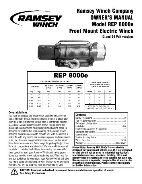
<strong>Ramsey</strong> <strong>Winch</strong> Company<br />
OWNER’S MANUAL<br />
Model <strong>REP</strong> <strong>8000e</strong><br />
Front Mount Electric <strong>Winch</strong><br />
12 and 24 Volt versions<br />
LINE PULL<br />
LINE SPEED<br />
(FPM)<br />
<strong>REP</strong> <strong>8000e</strong><br />
PERFORMANCE FIRST LAYER OF CABLE<br />
LINE SPEED<br />
(FPM)<br />
CURRENT<br />
(AMPS)<br />
CURRENT<br />
(AMPS)<br />
CABLE DRUM CAPACITY<br />
(5/16" (8 MM) DIA. CABLE)<br />
CUMULATIVE BY LAYER<br />
(lbs) (kg) 12V 24V 12V 24V LAYER FT.* M*<br />
0 0 15 18 40 10 1 15 4<br />
2,000 900 12 15 110 50 2 40 12<br />
4,000 1,810 10 12 170 100 3 70 21<br />
6,000 2,710 8 9 230 150 4 95 28<br />
8,000 3,620 6 6.5 310 210 * DEPENDS ON CABLE BEING<br />
UNIFORMLY WOUND ONTO DRUM.<br />
Congratulations<br />
You have purchased the finest winch available in its service<br />
class. The <strong>REP</strong> <strong>8000e</strong> features a highly efficient 3-stage planetary<br />
gear set. It transmits torque from a permanent magnet<br />
D.C. motor. A safe positive clutch allows free spooling for<br />
quick cable deployment. An automatic load holding brake is<br />
designed to hold the full rated capacity of the winch. It was<br />
designed and manufactured to provide you with the utmost in<br />
utility. As with any device that combines power and movement<br />
in its use, there are dangers if improperly used. At the same<br />
time, there are easier and faster ways for getting the job done<br />
if certain precautions are taken first. Please read this manual<br />
carefully. It contains useful ideas in obtaining the most efficient<br />
operation from your <strong>Ramsey</strong> <strong>Winch</strong> and safety procedures<br />
you need to know before beginning use. When you follow<br />
our guidelines for operation, your <strong>Ramsey</strong> <strong>Winch</strong> will give<br />
you many years of satisfying service. Thank you for choosing<br />
<strong>Ramsey</strong>. You will be glad you have one working for you.<br />
Contents<br />
Safety Precautions ......................................................2<br />
Tips for Safe Operation ................................................2<br />
Techniques of Operation ..............................................3<br />
Installation ................................................................4-6<br />
Electrical Connections & Operations ............................7<br />
Operating Instructions ..................................................7<br />
Maintenance ................................................................7<br />
Trouble Shooting Guide ................................................8<br />
<strong>Winch</strong> Parts List ....................................................9-10<br />
Warranty ......................................................Back Cover<br />
Please Note: <strong>Ramsey</strong> <strong>REP</strong> <strong>8000e</strong> Series winch is<br />
designed for front mount vehicle use. It is not designed<br />
for and should not be used in industrial applications<br />
(car haulers/carriers, wreckers, hoisting, etc.), and<br />
<strong>Ramsey</strong> does not warrant it to be suitable for such use.<br />
<strong>Ramsey</strong> makes a separate, complete line of winches for<br />
industrial/commercial use. Please contact the factory<br />
for further information.<br />
CAUTION: Read and understand this manual before installation and operation of winch.<br />
See Safety Precautions.
Safety Precautions To Guard Against<br />
Possible Injury…<br />
and finish spooling in cable by rotating the drum by<br />
hand with clutch disengaged. On hidden winches,<br />
spool in cable under power using supplied hook strap.<br />
A minimum of five wraps of cable around the drum<br />
barrel is necessary to hold the rated load. Cable<br />
clamp in not designed to hold the load.<br />
A. Keep yourself and others a safe distance to the side of<br />
the cable when pulling under load.<br />
B. Don't step over a cable, or near a cable under load.<br />
C. Use supplied hook strap when handling hook for<br />
spooling wire rope.<br />
D. Don't move the vehicle to pull a load on the winch<br />
cable. This could result in cable breakage.<br />
E. Use a heavy rag or gloves to protect hands from burrs<br />
when handling winch cable.<br />
F. Apply blocks to wheels when vehicle is on an incline.<br />
G. <strong>Winch</strong> clutch should be disengaged when winch is<br />
not in use and fully engaged when in use.<br />
H. Modification, alteration or deviation to the winch<br />
should only be made by <strong>Ramsey</strong> <strong>Winch</strong> Company.<br />
I. Keep the duration of your pulls as short as possible. If<br />
the motor becomes uncomfortably hot to the touch,<br />
stop and let it cool for a few minutes. Do not pull<br />
more than one minute at or near rated load. Do not<br />
maintain power to the winch if the motor stalls.<br />
Electric winches are for intermittent usage and should<br />
not used in constant duty applications.<br />
J. Disconnect the remote control switch from the winch<br />
when not in use. A <strong>Ramsey</strong> Part No. 282053 safety<br />
on-off switch in your vehicle is recommended.<br />
K. Note: Do not use winch in hoisting applications due to<br />
required hoist safety factors and features.<br />
L. Do not exceed maximum line pull ratings shown in<br />
tables. Shock loads must not exceed these ratings.<br />
M.To respool correctly, it is necessary to keep a slight<br />
load on the cable. This is accomplished by (wearing<br />
gloves) holding the cable with one hand and the<br />
remote control switch with the other, starting as far<br />
back and in the center as you can, walking up keeping<br />
load on the cable as the winch is powered in. Do not<br />
allow the cable to slip through your hand and do not<br />
approach the winch too closely. Turn off the winch<br />
and repeat the procedure until all the cable except a<br />
few feet is in. Disconnect the remote control switch<br />
Tips for Safe Operation<br />
Don't underestimate the potential danger in winching<br />
operations. Neither should you fear them. Do learn the<br />
basic dangers and avoid them.<br />
The uneven spooling of cable, while pulling a load, is not<br />
a problem, unless there is cable pileup on one end of<br />
drum. If this happens, reverse the winch to relieve the<br />
load and move your anchor point further to the center of<br />
the vehicle. After the job is done you can unspool and<br />
rewind for a neat lay of the cable.<br />
Store the remote control switch inside your vehicle<br />
where it will not become damaged. Inspect it before you<br />
plug it in.<br />
When ready to begin spooling in, plug in remote control<br />
switch with clutch disengaged. Do not engage clutch<br />
with motor running.<br />
Never connect the hook back to the cable. This causes<br />
cable damage. Always use a sling or chain of suitable<br />
strength as shown in the illustrations.<br />
Observe your winch while winching, if possible, while<br />
standing at a safe distance. If you use vehicle drive to<br />
assist, stop and get out every few feet to assure the<br />
cable is not piling up in one corner. Jamming cable can<br />
break your winch.<br />
Do not attach tow hooks to winch mounting apparatus.<br />
They must attach to vehicle frame.<br />
When double lining during stationary winching, the winch<br />
hook should be attached to the chassis of the vehicle.<br />
Since the greatest pulling power is achieved on the innermost<br />
layer of your winch, it is desirable to pull off as<br />
much line as you can for heavy pulls (remember, you<br />
must leave 5 wraps min. on the drum). If this is not<br />
practical, use a snatch block and double line arrangement<br />
(see illustration).<br />
Neat, tight spooling avoids cable binding, which is<br />
caused when a load is applied and the cable is pinched<br />
between two others. If this happens, alternately power<br />
the winch in and out a few inches. Do not attempt to<br />
work a bound cable under load; free by hand.<br />
2
Techniques of Operation<br />
The best way to get acquainted with how your winch<br />
operates is to make a few test runs before you actually<br />
need to use it. Plan your test in advance. Remember you<br />
hear your winch as well as see it operate. Get to recognize<br />
the sound of light steady pull, a heavy pull, and<br />
sounds caused by load jerking or shifting. Soon you will<br />
gain confidence in operating your winch and its use will<br />
become second nature with you.<br />
Your winch will not only pull your vehicle up or ease your<br />
vehicle down a steep grade, it will also pull another vehicle<br />
or a load while your vehicle is anchored in a stationary<br />
position. The following sketches show you a few<br />
techniques.<br />
When pulling a heavy load, place a blanket, jacket or tarpaulin<br />
over the cable five or six feet from the hook. It will<br />
slow the snap back in the event of a broken cable. Also<br />
open the vehicle hood for additional protection.<br />
Use the vehicle wheel power to help the winch, but don't<br />
overtake the winch line. Plan your pull. You can't always<br />
hook up and pull out in one step. Examine all the areas<br />
for anchoring possibilities as well as leverage situations,<br />
direction and goal.<br />
For basic self-recovery, anchor to a tree or heavy rock.<br />
When anchoring to a tree, always use a tree trunk protector.<br />
<strong>Winch</strong>es equipped with cable guide fairleads can pull<br />
from several different directions. Pull from an angle only<br />
to straighten up the vehicle--otherwise you can damage<br />
structural members or other parts of your vehicle and<br />
cause excess cable buildup on one end of the winch<br />
drum.<br />
Stakes driven into solid earth and chained together make<br />
a good anchor point for self-recovery when no solid<br />
anchor point is available.<br />
For a direct pull of 2,000 lbs. hitch a truck to a tree or<br />
solid anchor, and take out of gear.<br />
For a solid anchor, bury a log with earth or sand or place<br />
it in a deep ravine.<br />
To double the pull, use 2-part line and tie off the chassis.<br />
Take out of gear.<br />
3
Installation<br />
The winches shown in this owner's manual are solely and<br />
exclusively designed for vehicle mounted, non-industrial applications.<br />
All other applications will void warranty.<br />
Note: For specific bull-bar applications, the shifter lever on<br />
the winch may need to be repositioned. Refer to pages 5-6 for<br />
instructions on how to do this.<br />
It is very important that the winch be mounted on a flat surface<br />
so that the three major sections (the motor end, the cable<br />
drum and the gear housing end) are properly aligned. It is recommended<br />
that <strong>Ramsey</strong> kits be used to mount the winch.<br />
They are designed to align the winch and distribute up to the<br />
full rated load evenly, to avoid possible damage to the winch<br />
or vehicle. Note: If recommended mounting is not used, a kit<br />
of equal design must be used.<br />
Also available for mounting the <strong>REP</strong> <strong>8000e</strong> winch are the following<br />
winch mounting channels:<br />
#408052 Short length (23.63" black)<br />
#408120 Medium length (30.00" black)<br />
#408101 Long length (36.00" black)<br />
It is recommended that a <strong>Ramsey</strong> mounting channel be used<br />
in all non-<strong>Ramsey</strong> mountings.<br />
Position solenoid at about a 45° angle so that it clears lower<br />
winch guard tube of mounting kit. TIGHTEN CLAMP SECURE-<br />
LY.<br />
Attach fairlead to channel using hardware furnished with winch<br />
FIGURE 3<br />
(see FIGURE 3). Attach winch to channel. Place (4) flat washers<br />
and nuts into pockets of winch mounting feet and thread<br />
capscrews with lock washers through mounting holes in channel<br />
and into hardware in winch feet.<br />
Substitution of attaching hardware items (bolts, nuts or washers)<br />
different from those supplied with your winch and mounting<br />
kit can lead to failure causing damage or serious injury<br />
(use SAE grade 5 bolts or better and torque to 34 ft. lbs.)<br />
Place end of drum cable through fairlead and attach cable<br />
hook. Use clevis pin and cotter pin (see FIGURE 3).<br />
FIGURE 1<br />
When mounting winch, attach solenoid wires to motor terminals<br />
at end of motor. TIGHTEN NUTS ON MOTOR TERMINALS<br />
SECURELY (see FIGURE 1). Attach solenoid to mounting holes<br />
at end of long channel (see FIGURE 1) or use solenoid clamp<br />
to attach solenoid assembly to winch motor (see FIGURE 2).<br />
FIGURE 2<br />
4
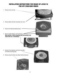
Repositioning the Shifter for Specific Bull Bar Applications<br />
Note: The shifter is positioned correctly for most applications. It will only need to be repositioned as necessary for<br />
specific bull bar applications.<br />
Refer to the Parts List and Exploded Parts Diagram for your specific winch elsewhere in this owner’s manual.<br />
1. Position winch as shown in Figure 4. Remove screws from tiebars. You may be able to loosen the screws at the<br />
motor end without removing them. Pull the Gear Housing assembly from the drum and shaft and set it down on<br />
the work bench with the Gear Housing Cover up. Remove the drum bushing from the Gear Housing assembly or<br />
the end of the drum. Set aside.<br />
2. Remove (6) capscrews<br />
from the Gear Housing<br />
Cover. Holding the Gear<br />
Housing Cover over the<br />
Gear Housing assembly,<br />
flip it over and set it on<br />
the workbench.<br />
Figure 4<br />
3. Gently lift the Gear Housing assembly,<br />
working the gears, bushings, etc. that<br />
are inside the Gear Housing out so that<br />
they are left stacked on the workbench.<br />
See Figure 5.<br />
4. Turn the Gear Housing assembly over<br />
and set on workbench. Remove the<br />
Retainer (item #37) by removing six<br />
capscrews (item #21) from Gear End<br />
Bearing (item 13). Once the retainer is<br />
removed, the Ring Gear (item #10),<br />
Cam Ring (item #36), and Locking<br />
Ring (item #34) can be lifted off the<br />
end bearing.<br />
Remove the six springs (item #38)<br />
from the end bearing.<br />
Figure 6<br />
5<br />
Figure 5
5. Determine position shifter knob needs to be for<br />
your application. Note: Shifter knob cannot be<br />
positioned too low or it will interfere with the feet<br />
on the Gear End Bearing (see Range of Position in<br />
Figure 7).<br />
6. To position the shifter knob, place locking ring in<br />
end bearing with stop post approximately 180°<br />
from where shifter knob needs to be positioned.<br />
Place cam ring over locking ring in proper position<br />
and confirm that shifter knob will move from<br />
engaged to disengaged position without interference.<br />
Mark position of stop post on end bearing.<br />
Figure 7<br />
7. Remove cam ring and locking ring from end bearing. Insert springs (item #38) into end bearing. When you<br />
replace the locking ring (item #34) over the springs, be sure the springs compress down into their recesses,<br />
and don’t bend sideways.<br />
8. Reassemble Gear Housing as shown in Figure 3. Make sure locking ring is positioned with stop post at marked<br />
location. The capscrews (item #38) for the retainer should be tightened to 40-45 in-lbs. Do not over-tighten.<br />
9. Place Gear Housing over the stacked gears, etc. that you removed in step 3. Gently work the housing over the<br />
stack, turning it as needed to mesh the planetary gears with the ring gear in the housing. Once they are all in the<br />
housing, flip the assembly over. Align the Gear Housing Cover and gasket with the holes in the ring gear. Replace<br />
the (6) capscrews that hold the Gear Housing Cover onto the Gear Housing. Tighten securely.<br />
10. Move the Shifter to the Disengaged position.<br />
11. Turn the Gear Housing over and set it on the work<br />
bench with the Gear Housing Cover down. See<br />
Figure 6.<br />
12. Install the drum bushing into the Gear Housing, confirming<br />
that the slot in the bushing is aligned with<br />
the key in the end bearing. See Figure 8. Pick up the<br />
rest of the winch (drum and motor end), and holding<br />
the drum, lower the winch onto the gear end.<br />
Stab the shaft into the gear end--you may need to<br />
turn the drum slightly to get the shaft to go all the<br />
way in.<br />
13. Place the tiebars on the motor end and gear end and<br />
fasten using (4) screws. Tighten securely.<br />
14. Once the winch is reassembled, turn it so that it is<br />
sitting on its feet. Confirm that the cable will<br />
freespool when the shifter is in the Disengaged position.<br />
Connect up the winch temporarily and confirm<br />
that the cable spools when the shifter is in the<br />
Engaged position.<br />
Figure 8<br />
6
Electrical Connections and Operations<br />
For normal self-recovery work, your existing electrical<br />
system is adequate. Your battery must be kept in good<br />
condition. A fully charged battery and proper connections<br />
are essential. Run the vehicle engine during winching<br />
operations to keep battery charged.<br />
Route red and black battery cables up to battery. CAU-<br />
TION: BE SURE BATTERY CABLES ARE NOT DRAWN<br />
TAUT ACROSS ANY SURFACES WHICH COULD POSSI-<br />
BLY DAMAGE THEM. Connect red cable to positive (+)<br />
battery terminal and black cable to negative (-) terminal.<br />
The remote control switch is waterproof. It has push button<br />
stations on either side. It is designed this way to prevent<br />
quick winch reversals, which lead to solenoid failure.<br />
Make sure the motor has stopped fully before<br />
reversing. To actuate winch simply plug remote control<br />
switch into receptacle in black solenoid cover of winch.<br />
Run winch forward and reverse to check connection and<br />
to determine winch operating directions.<br />
Snap appropriate "IN" and "OUT" disc into proper thumb<br />
cavity. The switch is also color coded to aid you in not<br />
having to guess at the direction your winch will run. DO<br />
NOT LEAVE SWITCH PLUGGED IN WHEN WINCH IS NOT<br />
IN USE.<br />
Operating Instructions<br />
The winch clutch allows rapid unspooling of the wire<br />
rope for hooking onto the load or anchor point. The<br />
clutch is operated by the shifter tab located on the gearhousing<br />
end of the winch as follows:<br />
1. To disengage the clutch, move the clutch shifter tab to<br />
the "OUT" position. Wire rope may now be freespooled<br />
off the drum.<br />
2. To engage the clutch, move the clutch shifter tab to<br />
the "IN" position. The winch is now ready for pulling.<br />
Maintenance<br />
All moving parts are permanently lubricated with high<br />
temperature lithium grease at the time of assembly.<br />
Under normal conditions factory lubrication will suffice.<br />
Lubricate cable periodically using light penetrating oil.<br />
Inspect the cable for broken strands and replace if necessary.<br />
If the cable becomes worn or damaged, it must<br />
be replaced.<br />
Corrosion on electrical connections will reduce perfomance<br />
or may cause a short. Clean all connections<br />
especially in remote control switch and receptacle. In<br />
salty environments use a silicone sealer to protect from<br />
corrosion.<br />
To minimize corrosion of the internal motor components<br />
that may occur due to condensation, power the winch in<br />
or out periodically. Energizing the motor will generate<br />
heat which will help dissipate any moisture buildup in the<br />
motor. This should be performed at periodic intervals<br />
(such as with each oil change to your vehicle). Note:<br />
Refer to the Troubleshooting Guide if the motor has been<br />
submerged.<br />
Cable Installation<br />
Unwind the new cable by rolling it out along the ground,<br />
to prevent kinking. Remove old cable and observe the<br />
manner in which it is attached to the cable drum flange.<br />
Before installing the new cable assembly, make sure end<br />
of cable is squarely cut and wrapped with tape to prevent<br />
fraying. Form a short 90° bend (approximately ½" long)<br />
in one end of the cable.<br />
Position the cable drum so that the large 13/32" diameter<br />
hole in the motor end drum flange is approximately on<br />
the top. Insert the bent end of cable into the 13/32" hole<br />
in the drum flange and then carefully run the winch in the<br />
"reel in" direction approximately ¾ revolution until the ¼"<br />
diameter threaded hole in the drum flange is on top.<br />
Secure the cable to the drum flange using cable anchor<br />
and capscrew shown in the parts drawing. Securely<br />
tighten the capscrew, but do not over-tighten.<br />
Wind 5 wraps of cable onto the drum. <strong>Winch</strong> on the rest<br />
of the cable by pulling in a light load to keep the tension<br />
constant. Allow the cable to swivel by using a length of<br />
chain or a block between the cable hook and the load.<br />
7
Troubleshooting Guide<br />
CONDITION POSSIBLE CAUSE CORRECTION<br />
MOTOR RUNS IN ONLY ONE<br />
DIRECTION<br />
(1) Defective solenoid or stuck solenoid (1) Jar solenoid to free contacts. Check by applying 12<br />
volts to coil terminal (it should make an audible click when<br />
energized)<br />
(2) Defective remote control switch (2) Disengage winch clutch, remove remote control switch<br />
plug from the socket and jump pins at 8 and 4 o’clock.<br />
Motor should run. Jump pins at 8 and 10 o’clock. Motor<br />
should run.<br />
MOTOR RUNS EXTREMELY HOT (1) Long period of operation (1) Cooling-off periods are essential to prevent<br />
overheating.<br />
MOTOR RUNS, BUT WITH<br />
INSUFFICIENT POWER, OR WITH<br />
LOW LINE SPEED<br />
(1) Insufficient battery (1) Check battery terminal voltage under load. If 10 volts or<br />
less, replace or parallel another battery to it.<br />
(2) Bad connection (2) Check battery cables for corrosion; clean and grease.<br />
(3) Insufficient charging system (3) Replace with larger capacity charging system.<br />
MOTOR RUNS, BUT DRUM DOES<br />
NOT TURN<br />
MOTOR WILL NOT OPERATE<br />
MOTOR WATER DAMAGED<br />
(1) Clutch not engaged (1) If clutch engaged but symptom still exists, it will be<br />
necessary to disassemble winch to determine cause and<br />
repair.<br />
(1) Defective solenoid or stuck solenoid (1) Jar solenoid to free contacts. Check solenoid by<br />
applying 12 volts to coil terminal (it should make an<br />
audible click when energized).<br />
(2) Defective remote control switch (2) Disengage winch clutch, remove remote control switch<br />
plug from the socket and jump pins at 8 and 4 o’clock.<br />
Motor should run. Jump pins at 8 and 10 o’clock. Motor<br />
should run.<br />
(3) Defective motor (3) If solenoids operate, check for voltage at armature<br />
post; replace motor.<br />
(4) Loose connections (4) Tighten connections on bottom side of hood and on<br />
motor.<br />
(1) Submerged in water or water from<br />
high pressure car wash<br />
(1) Allow to drain and dry thoroughly, then run motor<br />
without load in short bursts to dry windings.<br />
CABLE DRUM WILL NOT<br />
FREESPOOL OR IS DIFFICULT TO<br />
FREESPOOL<br />
(1) Clutch not disengaged (1) Check clutch operation according to nameplate. Make<br />
sure clutch shifter knob is fully at “OUT” position.<br />
(2) <strong>Winch</strong> not mounted squarely<br />
causing end bearing to bind drum<br />
(2) Check mounting to see that installation instructions on<br />
page 4 have been followed.<br />
(3) Some or all of the (6) 414861 flat<br />
head capscrews attaching the 479007<br />
ring gear retainer are too tight<br />
(3) Remove the gear housing cover, 413018, and all gears<br />
from inside the gear housing. Disengage the clutch and<br />
check to see that the ring gear will rotate by hand. If it will<br />
not, using a hex (allen) wrench, slightly loosen all the<br />
capscrews and then snugly re-tighten them in criss-cross<br />
pattern, but do not over-tighten. The ring gear must rotate<br />
by hand. Re-assemble winch.<br />
8
Hawse Fairlead<br />
Replacement Kit #251152<br />
Included with the <strong>REP</strong> <strong>8000e</strong><br />
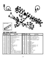
<strong>REP</strong> <strong>8000e</strong> PARTS LIST<br />
Item<br />
Item<br />
Qty. Parts No.<br />
Description<br />
Qty. Parts No.<br />
No.<br />
No.<br />
Description<br />
1 1 247004 Input Gear Carrier Ass’y.—12V 20 6 416273 Screw #6—32NCx3/8 Lg. Fil. Hd.<br />
1 247009 Input Gear Carrier Ass’y.—24V 21 4 418018 Nut 1/4—20NC Hx. Reg. Elastic Stop<br />
2 1 247007 Intermediate Gear Carrier Ass’y 22 4 418035 Nut 3/8—16NC Hx. Reg. Z/P<br />
3 1 247008 Output Gear Carrier Ass’y 23 4 418177 Lockwasher 3/8 ID Med. Sect. Plated<br />
4 1 251110 Switch Ass’y 24 4 418181 Washer—Flat 3/8 ID S.A.E., Plated<br />
5 1 251118 Cable Assembly-95’ 5/16” (8MM) Dia. 25 1 424023 Clamp<br />
6 1 278155 Solenoid Ass’y—12V 26 1 442207 Gasket<br />
1 278042 Solenoid Ass’y—24V 27 1 444048 Output Sun Gear<br />
7 1 296181 Brake/Shaft Ass’y 28 1 448046 Cable Anchor<br />
8 1 332128 Drum—Cable 29 2 448049 Tie Bar<br />
9 1 334143 Ring Gear 30 1 458109 Motor/End Bearing Ass’y.—12V<br />
10 1 334147 Intermediate Sun Gear 1 458046 Motor/End Bearing Ass’y.—24V<br />
11 1 334153 Input Sun Gear—12V 31 1 470053 Roll Pin 1/8 Dia. x 3/8<br />
1 334154 Input Sun Gear—24V 32 1 477002 Locking Ring<br />
12 1 338249 End Bearing 33 1 477003 Cam Ring<br />
13 2 412056 Bushing—Drum 34 2 477004 Ring—Half<br />
14 1 412061 Bushing—Shaft 35 1 479007 Retainer—Ring Gear<br />
15 1 413018 Cover—Gear Housing 36 6 494077 Spring<br />
16 4 414316 Capscrew 3/8—16NCx1-1/4Lg.Hx.Hd.Gr.5,Z/P 37 3 518020 Thrust Washer<br />
17 4 414829 Capscrew 1/4—20NCx1 Lg. Soc. Button Hd. 38 1 518027 Thrust Disc<br />
18 1 414830 Capscrew 1/4—20NCx3/8 Lg. Soc. Button Hd.<br />
19 6 414861 Capscrew 1/4—20NCx3/4 Lg. Flat Hd. Soc. NYLOK<br />
9
Solenoid Assembly Parts List <strong>REP</strong> <strong>8000e</strong><br />
278155--12V<br />
278042--24V<br />
Note: All unidentified hardware comes<br />
supplied with the solenoid.<br />
Item<br />
No.<br />
Qty.<br />
Req'd Part No. Description<br />
1 2 289168 Wire Assembly—Black 4 Ga. x 12” Lg.—12V<br />
2 289089 Wire Assembly—Black 6 Ga. x 12” Lg.—24V<br />
2 1 289090 Wire Assembly—Black 10 Ga. x 3” Lg<br />
3 1 289091 Wire Assembly—Black 16 Ga. x 1-1/2” Lg<br />
4 1 289169 Wire Assembly—Black 4 Ga. x 3-1/2” Lg—12V<br />
1 289092 Wire Assembly—Black 6 Ga. x 3-1/2” Lg—24V<br />
5 2 364002 Strap—Copper<br />
6 1 408102 Bracket<br />
7 1 413024 Cover—Solenoid<br />
8 3 414053 Capscrew 1/4—20NCx1-1/4Lg.Hx.Hd. Z/P<br />
9 7 416216 Screw #10—24NCX 1/2” Lg. Rd. Hd. Z/P<br />
10 2 416227 Screw #10—24NCX 3/4” Lg. Truss Hd. Black<br />
11 6 418004 Nut—Hx. Reg. #10—24NC Z/P<br />
12 6 418014 Nut—Hx. Reg 1/4—20NC Z/P<br />
13 4 418140 Washer #10 SAE Flat Z/P<br />
14 2 418141 Lockwasher #10 Med. Sect. Z/P<br />
15 3 418149 Lockwasher 1/4 Med. Sect. Z/P<br />
16 1 418165 Washer 5/16 Shakeproof External Teeth<br />
17 3 418411 Nutsert #10—24NC<br />
18 3 418514 Spacer<br />
19 1 430013 Connector Female—Molded<br />
20 2 440071 Terminal Tab<br />
21 2 440110 Solenoid—12V<br />
2 440114 Solenoid—24V<br />
22 1 440111 Strap—Copper<br />
23 1 440112 Wire Assembly—Battery Red 60”<br />
24 1 440113 Wire Assembly—Battery Black 60”<br />
25 1 482029 Cover—Female Connector<br />
10
NOTES
Warranty Information<br />
<strong>Ramsey</strong> <strong>Winch</strong>es are designed and built to exacting specifications. Care and skill go into every winch we make. If<br />
the need should arise, warranty procedure is outlined on the back of your self-addressed postage paid warranty<br />
card. Please read and fill out the enclosed warranty card and send it to <strong>Ramsey</strong> <strong>Winch</strong> Company. If you have problems<br />
with your winch, please follow instructions for proper service on all warranty claims.<br />
<strong>Ramsey</strong> <strong>Winch</strong> offers a limited lifetime warranty for each new<br />
<strong>Ramsey</strong> winch against manufacturing defects in workmanship and<br />
materials on all mechanical components.<br />
Warranty registration cards for each winch must be submitted at the<br />
time of purchase or within 30 days. Warranty will only be valid for<br />
the original purchase of the winch and installed on the vehicles with<br />
which they were originally registered.<br />
New cable assemblies are warranted against defects in workmanship<br />
and materials. No warranty applies after initial use.<br />
All <strong>Ramsey</strong> mounting kits and other accessories carry a 1-year limited<br />
warranty against defects in material and workmanship.<br />
Chrome finish warranted for one year against manufacturing defects.<br />
Cracking, scratching, or corrosion caused by winching not covered<br />
by warranty.<br />
This warranty is void if winch is used in commercial/industrial applications<br />
other than front mount self-recovery.<br />
Electrical components consisting of motors, solenoids, wiring, wire<br />
connectors and associated parts carry a 1-year limited warranty.<br />
Battery isolators carry a 90-day limited warranty.<br />
An optional extended 2-year limited warranty for all electrical components<br />
may be purchased.<br />
The obligation under this Warranty, statutory or otherwise, is limited<br />
to the replacement or repair at the manufacturer’s factory, or at a<br />
point designated by the manufacturer, upon inspection of such part,<br />
to have been defective in material or workmanship. This Warranty<br />
does not obligate <strong>Ramsey</strong> <strong>Winch</strong> Company to bear the cost of transportation<br />
charges in connection with the replacement or repair of<br />
defective parts, nor shall it apply to a product upon which repairs or<br />
alterations have been made, unless authorized by the manufacturer,<br />
or for equipment misused, neglected, or improperly installed.<br />
IMPORTANT NOTICE: To the fullest extent permitted by applicable<br />
law, the following aare hereby excluded and disclaimed:<br />
1. All warranties of fitness for a particular purpose; 2. All<br />
warranties of merchantability; 3. All claims for consequential<br />
or incidental damages. There are no warranties that extend<br />
beyond the description that appears on the face hereof.<br />
Some states do not allow the above exclusions or disclaimers<br />
in consumer transactions and as such this disclaimer/exclusion<br />
may not apply to your particular case.<br />
To the extent such warranties of fitness for a particular purpose<br />
or merchantability are deemed to apply to this product,<br />
they exist for only so long as the express limited warranty<br />
elsewhere set forth is in existence.<br />
<strong>Ramsey</strong> <strong>Winch</strong> Company makes no warranty in respect to accessories,<br />
same being subject to the warranties of their respective manufacturers.<br />
<strong>Ramsey</strong> <strong>Winch</strong> Company, whose policy is one of continuous product<br />
improvement, reserves the right improve any product through<br />
changes in design and materials as it may deem desirable without<br />
being obligated to incorporate such changes in products of previous<br />
manufacture.<br />
If field service at the request of the buyer is rendered and the fault is<br />
found not to be with <strong>Ramsey</strong> <strong>Winch</strong> Company’s product, the buyer<br />
shall pay the time and expense cost of the field representative. Bills<br />
for service, labor, or other exposes which have been incurred by the<br />
buyer without express approval or authorization by <strong>Ramsey</strong> <strong>Winch</strong><br />
Company wil not be accepted.<br />
This warranty gives you specific legal rights and you may also have<br />
other legal rights which vary from state to state.<br />
<strong>Ramsey</strong> <strong>Winch</strong> Company<br />
P.O. Box 581510 - Tulsa, OK 74158-1510 USA - Phone: (918) 438-2760 - Fax (918) 438-6688<br />
Visit us at http://www.ramsey.com<br />
OM-914101-0603-E