IMPORTANT NOTES! WARNING - Ramsey Winch
IMPORTANT NOTES! WARNING - Ramsey Winch
IMPORTANT NOTES! WARNING - Ramsey Winch

Create successful ePaper yourself
Turn your PDF publications into a flip-book with our unique Google optimized e-Paper software.
INSTALLATION INSTRUCTIONS FOR<br />
WRAPAROUND KIT #295356<br />
ON 1999-2004 FORD F250 – F550<br />
WITH RPH 12,000 FRONT MOUNT WINCH # 123305<br />
NOTICE<br />
<strong>Ramsey</strong> kits are designed for use with <strong>Ramsey</strong> <strong>Winch</strong>es only.<br />
Use or sales of kits for other winches or applications voids warranty.<br />
<strong>WARNING</strong><br />
<strong>Ramsey</strong> offers mounting kits and winches for various vehicles. In crash tests on a limited number<br />
of automotive manufacturer's vehicles, winches/mounting kits, which have been properly<br />
mounted, have not interfered with air bag operation.<br />
The user/customer, or their installer, must verify that the mounting kit does not interfere with the<br />
factory air bag sensors, which must not be relocated or modified in any way.<br />
The user/customer should follow the vehicle manufacturer's recommendations and those of a<br />
qualified mechanic to determine if the winch/mounting kit might interfere with the air bag<br />
operation. The user/customer should then determine the suitability of a winch/mounting kit on a<br />
particular vehicle.<br />
PLEASE BE ADVISED THAT THE VEHICLE'S AIR BAG SYSTEM MAY NOT OPERATE<br />
PROPERLY IF THE WINCH/MOUNTING KIT IS NOT MOUNTED IN COMPLIANCE WITH THE<br />
VEHICLE MANUFACTURER'S RECOMMENDATIONS.<br />
DO NOT ATTACH TOW HOOK TO ANY PART OF MOUNTING KIT UNLESS INSTRUCTED TO<br />
DO SO.<br />
DO NOT SUBSTITUTE ATTACHING HARDWARE ITEMS (BOLTS, NUTS, OR WASHERS).<br />
READ AND UNDERSTAND WINCH OWNER'S MANUAL BEFORE INSTALLATION AND<br />
OPERATION OF WINCH. SEE <strong>WARNING</strong>S, CAUTIONS, AND OPERATION.<br />
<strong>IMPORTANT</strong> <strong>NOTES</strong>!<br />
1. RIGHT AND LEFT HAND DIRECTIONS AS IF SEATED BEHIND STEERING WHEEL.<br />
2. ALL FASTENING HARDWARE MUST BE LOOSELY ASSEMBLED UNTIL DIRECTED TO TIGHTEN.<br />
RAMSEY WINCH COMPANY<br />
P.O. BOX 581510<br />
TULSA, OKLAHOMA 74158<br />
KI-913344-0803-D
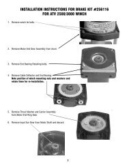
STEP 1<br />
Unfasten plastic splashguard from radiator support bracket. Remove vehicle tow hooks and vehicle<br />
bumper. Remove and discard shims hanging from front of vehicle frame.<br />
Enlarge rectangular cutout in bumper bracket by 1/2" at top and 1/4” at bottom. See REAR VIEW OF<br />
BUMPER below.<br />
Attach nut plate #4 to inside of bracket assembly #7 & #8 using (2) 1/2-13NC x 1-1/4 lg. capscrews<br />
#16 with lockwashers #21, and flatwashers #22, in the two front holes each side.<br />
You will need assistance for this step.<br />
While holding bumper in place, install end of R.H. and L.H. bracket assemblies through bumper and<br />
bumper brackets and into ends of R.H. and L.H. vehicle frame. Secure brackets to front of frame<br />
using (2) 1/2-13NC x 1-1/2 lg. capscrews #13, with lockwashers #21, nuts #19 and nut strips #1, each<br />
side. DO NOT TIGHTEN HARDWARE COMPLETELY.<br />
1
STEP 2<br />
Remove (4) bumper bracket bolts from each side of bumper. This allows bumper to move forward to<br />
provide access to lower bracket bolts. Use (3) 1/2-13NC x 1-1/2 lg. capscrews #13, with lockwashers<br />
#21 through bottom of vehicle frame and into nut plate attached to bracket assemblies, each side.<br />
Tighten hardware to full torque. (See torque value chart, page 6).<br />
Reattach bumper to bumper brackets and tighten all hardware to full torque. Use bracket assembly<br />
#7 & #8 as a template to drill (2) 9/16 DIA. holes through bumper brackets, as shown below. Install<br />
(2) 1/2-13NC x 1-1/2lg. capscrews #13, with lockwashers #21, nuts #19 and nut strips #1, each side.<br />
Reattach vehicle tow hooks to underside of bracket assembly #7 & #8 using M12 x 1.75 x 50mm<br />
capscrews. Discard the existing bolts. Tighten to full torque. (See torque value chart, page 6).<br />
Reattach splashguard.<br />
2
STEP 3<br />
Place frame assembly #3 between bracket assemblies #7 & #8 and R.H. & L.H. side plates #2 to the<br />
outsides of bracket assemblies. Use (3) 1/2-13NC x 1-1/2 lg. carriage bolts #15 and (1) 1/2-13NC x<br />
1-1/4 lg. carriage bolt #14, with lockwashers #21, and nuts #19 (each side), as shown, to attach side<br />
plates and brackets to frame assembly. DO NOT TIGHTEN HARDWARE.<br />
Install (1) tube assembly #6 at top between side plates #2, placing shims #23 between side plates<br />
and ends of tube. Secure using (1) 3/8-16 NC X 3/4 lg. hex socket button head capscrew #17 at<br />
each end. Attach light tube assemblies #9 to side plates, as shown. Use (2) 3/8-16NC x 1 lg.<br />
carriage bolts #10, with lockwashers #20 and nuts #18, each side.<br />
3
STEP 4<br />
Remove base tie bars from bottom of winch end bearings. Place winch in cavity of frame #3 on top of<br />
mounting plate. Place (2) base tie bars between the rear winch feet and the mounting plate. Place<br />
the other two base tie bars between the front winch feet and the mounting platform. Secure using (8)<br />
1/2-13NC X 1-1/2 lg. hex hd. capscrews inserted through 1/2” lockwashers then through mounting<br />
plate, base tie bars, and into tapped holes in winch feet. Tighten securely. (See torque value chart,<br />
page 6).<br />
Install remaining bottom tube assembly #6 between side plates #2, placing shims #23 between side<br />
plates and ends of tube. Secure using (1) 3/8-16 NC X 3/4 lg. hex socket button head capscrew #17<br />
at each end. Tighten all hardware to proper torque value (see Torque value chart, page 6).<br />
4
STEP 5<br />
Place roller fairlead over holes in mounting plate. Install (2) 3/8-16 NC X 1 lg. capscrews #11 through<br />
(2) 3/8” lockwashers #20, then through inside holes in mounting plate and into the threaded holes in<br />
bottom of roller guide. Install (2) 3/8-16 NC X 1-1/2 lg. capscrews #12 through outside holes of<br />
mounting plate and roller guide and secure using (2) 3/8 lockwashers #20, and (2) nuts #18. Tighten<br />
hardware to proper torque value (see Torque value chart, page 6).<br />
SEE PAGE 2 OF WINCH OWNER’S MANUAL FOR CABLE INSTALLATION, PAGE 3 FOR<br />
HYDRAULIC SCHEMATICS, AND PAGE 14 (VIEW A-A) FOR HYDRAULIC LINES INSTALLATION.<br />
REFER TO WINCH OWNER'S MANUAL FOR PROPER OPERATIONS.<br />
5
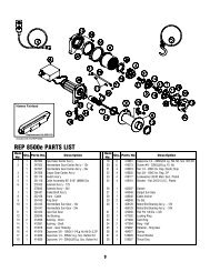
PARTS LIST FOR KIT #295356 (BLACK)<br />
ITEM NO. QTY. PART NO. DESCRIPTION<br />
1 4 364165 NUT STRIP<br />
2 2 265073 SIDE PLATE R.H. & L.H.-BLACK<br />
3 1 265083 FRAME ASSEMBLY-WINCH MNTG.<br />
4 2 350666 PLATE-NUT<br />
6 2 395272 TUBE ASSEMBLY (BLACK)<br />
7 1 395380 BRACKET ASSEMBLY-R.H.<br />
8 1 395381 BRACKET ASSEMBLY-L.H.<br />
9 2 395386 LIGHT TUBE ASSEMBLY (BLACK)<br />
10 4 414220 CARRIAGE BOLT 3/8-16NC X 1 LG. GR.5 BLACK<br />
11 2 414321 CAPSCREW 3/8-16NC X 1" LG. HX. HD. GR.5 BLACK<br />
12 2 414322 CAPSCREW 3/8-16NC X 1-1/2 LG. HX. HD. GR.5 BLACK<br />
13 14 414551 CAPSCREW 1/2-13NC X 1-1/2 LG. HX. HD. GR.5 BLACK<br />
14 2 414559 CARRIAGE BOLT 1/2-13NC X 1-1/4 LG. GR.5 BLACK<br />
15 6 414560 CARRIAGE BOLT 1/2-13NC X 1-1/2 LG. GR.5 BLACK<br />
16 4 414592 CAPSCREW 1/2-13NC x 1-1/4 LG. HX. HD. GR.5 BLACK<br />
17 4 414937 CAPSCREW 3/8-16NC X 3/4 LG. HX. SOC. BUTTON HD. BLK.<br />
18 6 418033 NUT 3/8-16NC HX. REG.-BLACK<br />
19 16 418072 NUT 1/2-13NC HX. REG.-BLACK<br />
20 8 418175 LOCKWASHER 3/8 MED. SECT.-BLACK<br />
21 26 418216 LOCKWASHER 1/2 MED. SECT.-BLACK<br />
22 4 418229 WASHER 1/2 FLAT<br />
23 4 488011 SHIM-PLASTIC<br />
24 6 415311 CAPSCREW M12 X 1.75 X 50 HX HD GR8.8 Z/P<br />
TORQUE VALUE CHART<br />
SIZE TORQUE FT./LB. NM<br />
3/8-16 39 52<br />
1/2-13 87 118<br />
6