
Create successful ePaper yourself
Turn your PDF publications into a flip-book with our unique Google optimized e-Paper software.
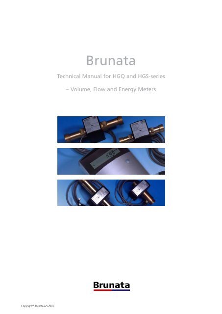
<strong>Brunata</strong><br />
Technical Manual for HGQ and HGS-series<br />
– Volume, Flow and Energy Meters<br />
Copyright ® <strong>Brunata</strong> a/s 2006
<strong>Brunata</strong> HG meters<br />
In 1999 <strong>Brunata</strong> took over HG International a/s, a modern<br />
wholly Danish owned company focusing on the development<br />
and production of electronic water and energy meters based<br />
on the magnetic induction metering principle. Thanks to an<br />
unswerving commitment to new technology we today supply<br />
some of the most advanced, reliable and accurate meters on<br />
the market.<br />
Since production began in 1953 the HG meters have undergone<br />
a considerable transformation. They have changed from being<br />
mechanical to fully electronic devices without a single moving<br />
part. The electronics have become increasingly compact, and<br />
the functionality has expanded enormously. Today’s meters<br />
are like small computers, with all the software contained on a<br />
single integrated circuit.<br />
Today, our range of products includes meters for hot and cold<br />
water and for energy metering in heating and cooling systems.<br />
We offer on of the widest selections of meters on the market,<br />
covering capacities from 1 l/h to 660 m 3 /h.<br />
The <strong>Brunata</strong> Group<br />
<strong>Brunata</strong> is a wholly Danish owned production and engineering<br />
company with approx. 400 employees that develops and manufactures<br />
mechanical and electronic equipment for the metering<br />
of heat and water and that also prepares the associated billing.<br />
In Denmark, <strong>Brunata</strong> has its head office in the outskirts<br />
of Copenhagen and is represented nationwide through local<br />
branches. Furthermore, the company exports to most European<br />
countries through subsidiaries and license partners.<br />
UK-QB 10.1481/11.04.2006<br />
<strong>Brunata</strong> a/s · Vesterlundvej 14 · DK-2730 Herlev · Phone +45 77 77 70 00 · Fax +45 77 77 70 01<br />
www.brunata.dk · brunata@brunata.dk<br />
Page of 32 Copyright ® <strong>Brunata</strong> a/s 2006
Table of contents<br />
1. Introduction......................................................... 4<br />
2. Reference documents........................................... 4<br />
2.1 Nomenclature list............................................ 4<br />
2.1.1 Temperatures....................................... 4<br />
2.1.2 Flow-rates............................................ 4<br />
2.1.3 Miscellaneous ..................................... 4<br />
2.2 List of appendixes........................................... 5<br />
3. General Description.............................................. 5<br />
3.1 HGQ / HGS Volume Meter.............................. 5<br />
3.2 HGQ / HGS Heat and Cooling Energy Meter... 6<br />
3.2.1 HGS-IV integration unit....................... 7<br />
3.3 Flow sensors................................................... 7<br />
3.4 HGQ / HGS Electronics.................................... 7<br />
3.5 Temperature sensors....................................... 7<br />
3.5.1 Direct sensors...................................... 7<br />
3.5.2 Pocket sensors with fixed cable............ 7<br />
3.5.3 Head sensors....................................... 8<br />
3.6 Type approvals................................................ 8<br />
3.7 Accuracy......................................................... 8<br />
3.7.1 The total MPE ..................................... 8<br />
3.7.2 MPE for subassemblies........................ 8<br />
3.8 Types and versions.......................................... 8<br />
4. Operating principles .......................................... 10<br />
4.1 Operating principles for HGQ/HGS meters.... 10<br />
4.2 HGS-IV integration unit............................... 10<br />
4.3 Volume measuring........................................ 10<br />
4.4 Temperature measuring................................ 10<br />
4.5 Energy calculation......................................... 10<br />
4.6 Menu structure and description.....................11<br />
4.7 Display functions...........................................11<br />
4.8 Accounting dates.......................................... 13<br />
4.9 Tariff function .............................................. 14<br />
4.10 Back light ............................................... 14<br />
4.11 Mean value algorithm............................. 14<br />
4.12 Reset function......................................... 14<br />
4.13 Flow rates above q s<br />
................................. 14<br />
4.14 Flow rates below q i<br />
................................. 15<br />
4.15 Back-up battery....................................... 15<br />
4.15.1 Battery Function................................. 15<br />
4.15.2 Change of battery.............................. 15<br />
4.16 Info and error codes................................ 15<br />
4.17 Stored data and recovery........................ 16<br />
5. Dimensions........................................................ 16<br />
5.1 Flow sensors................................................. 16<br />
5.1.1 HGQ.................................................. 16<br />
5.1.2 HGS................................................... 16<br />
5.2 Electronics................................................... 17<br />
5.2.1 standard............................................ 17<br />
5.2.2 OEM-version..................................... 17<br />
5.3 Temperature sensors..................................... 17<br />
5.3.1 Direct sensors DS................................. 17<br />
5.3.2 Pocket sensors PS with fixed cable ...... 17<br />
5.3.3 Head sensors....................................... 18<br />
6. Pressure ratings and .......................................... 18<br />
7. Input / Output.................................................... 19<br />
7.1 HGQ/HGS Standard electronics.................... 19<br />
7.2 HGQ/HGS – 107 electronics.......................... 19<br />
7.3 HGQ/HGS OEM electronics........................... 19<br />
7.4 Pulse input specifications.............................. 19<br />
7.4.1 Pulse Input (AUX1 & AUX2) - Connection.. 19<br />
7.4.2 Description of the AUX input .............. 20<br />
7.4.3 Prescaler.............................................. 20<br />
7.5 Pulse output specifications............................ 21<br />
7.5.1 Pulse Output - Connection<br />
(Galvanic separated).......................... 22<br />
7.5.2 Pulse Output - Connection (NOT galvanic<br />
separated)................................. 22<br />
7.5.3 Minimum Volume/Pulse value V p for q s... 22<br />
7.5.4 Volume/flow pulse value ..................... 22<br />
7.5.5 Max. measurable flow before limit ...... 23<br />
8. Data communication.......................................... 26<br />
8.1 Data protocol............................................... 26<br />
8.1.1 M-Bus protocol.................................... 26<br />
8.1.2 M-Bus telegram................................... 26<br />
8.2 Addressing of communicationmodules ........ 26<br />
8.3 RS232 module.............................................. 27<br />
8.4 M-Bus module.............................................. 27<br />
8.5 LON module................................................. 27<br />
8.6 Analogue output device............................... 27<br />
8.7 Communication modem .............................. 27<br />
9. Test and adjustment........................................... 28<br />
9.1 Displaying high resolution volume pulses...... 28<br />
9.2 Verification................................................... 28<br />
9.3 Calibration.................................................... 28<br />
9.4 Zeroing of peak values.................................. 29<br />
9.5 Clock adjustment.......................................... 29<br />
10. Installation requirements.................................... 29<br />
10.1 Installing the Flow Sensor........................ 29<br />
10.2 Mounting and connections of<br />
the electronic unit................................... 29<br />
10.3 Temperature sensors............................... 29<br />
10.4 Security seals........................................... 29<br />
10.5 Starting up the meter.............................. 29<br />
UK-QB 10.1481/11.04.2006<br />
Copyright ® <strong>Brunata</strong> a/s 2006<br />
Page of 32
1. Introduction<br />
This manual is intended for skilled technicians and accredited<br />
laboratory personal.<br />
The HGQ, HGS and HGS-IV Meters are designed as Volume<br />
Meters (versions 107 – 178) and Energy Meters (versions<br />
180 and 189) covering the flow range from 1.2 to 16 m 3 /h<br />
and are able to measure accurate flow rates of liquids with<br />
a conductivity > 20 μS/cm.<br />
This manual covers the HGQ and HGS versions EG; i.e. hardware<br />
version E and software version G.<br />
HGS-IV is an integration unit designed for using an external<br />
flowsensor.<br />
HGQ and HGS meters are designed for measuring of thermal<br />
heat energy in district heating and cooling systems or in the<br />
industry. The HGQ series is designed especially for individual<br />
one family houses and dwellings.<br />
This manual applies to all versions, the term HGQ/HGS means<br />
that HGQ as well as HGS and HGS-IV are covered.<br />
2. Reference documents<br />
2.1 Nomenclature list<br />
Reference: EN 1434<br />
2.1.1 Temperatures<br />
Θ max<br />
Θ min<br />
∆Θ<br />
The upper limit of the temperature range, q max<br />
is the<br />
highest temperature of the heat conveying liquid,<br />
at which the heat meter shall function without the<br />
Maximum Permissible Errors (MPE) being exceeded.<br />
The lower limit of the temperature range, q min<br />
is the<br />
lowest temperature of the heat conveying liquid, at<br />
which the heat meter shall function without the Maximum<br />
Permissible Errors (MPE) being exceeded.<br />
The temperature difference, ∆Θ, is the absolute value<br />
of the difference between the temperatures of the<br />
heat conveying liquid at the flow and return of the<br />
heat-exchange circuit.<br />
∆Θ max<br />
The upper limit of the temperature difference, ∆Θ max<br />
is the highest temperature difference, at which the<br />
heat meter shall function within the upper limit of<br />
thermal power without the Maximum Permissible<br />
Errors (MPE) being exceeded.<br />
∆Θ min<br />
t F<br />
t R<br />
t L<br />
t H<br />
The lower limit of the temperature difference, ∆Θ min<br />
is the lowest temperature difference, above which<br />
the heat meter shall function within the upper limit<br />
of thermal power without the Maximum Permissible<br />
Errors (MPE) being exceeded.<br />
Forward temperature, inlet<br />
Return temperature, outlet<br />
<br />
Temperature low is return temperature in heating systems<br />
and forward temperature in cooling systems.<br />
<br />
Temperature high is forward temperature in heating<br />
systems and return temperature in cooling systems.<br />
2.1.2 Flow-rates<br />
q s<br />
q p<br />
q i<br />
q<br />
According to EN 1434 the upper limit of the flow-rate,<br />
q s<br />
, is the highest flow-rate, at which the meter shall<br />
function for short periods (< 1h/day; < 200 h/year)<br />
without the Maximum Permissible Errors (MPE) being<br />
exceeded. HGQ/HGS meters have no period limitations.<br />
The permanent flow-rate, q p<br />
, is the highest flowrate,<br />
at which the meter shall function continuously<br />
without the Maximum Permissible Errors (MPE) being<br />
exceeded.<br />
The lower limit of the flow-rate, q i<br />
, is the lowest flowrate,<br />
above which the meter shall function for short<br />
periods (< 1h/day; < 200 h/year) without the Maximum<br />
Permissible Errors (MPE) being exceeded.<br />
Current flow-rare<br />
2.1.3 Miscellaneous<br />
UK-QB 10.1481/11.04.2006<br />
MPE<br />
t on<br />
t off<br />
T<br />
Maximum Permissible Error<br />
Time of the conducting state of an opto coupler input<br />
and output.<br />
Time of the non-conducting state of an opto coupler<br />
input and output.<br />
Pulse period. T = t on<br />
+ t off<br />
Page of 32 Copyright ® <strong>Brunata</strong> a/s 2006
V p<br />
v<br />
k<br />
BxRy<br />
EC<br />
Volume pulse value (litre/pulse)<br />
The water volume flow velocity<br />
The water heat coefficient (enthalpy) from heat<br />
enthalpy table, ref. EN 1434.<br />
Data bank x, Register y. Internal data, not accessible<br />
by the user.<br />
ErrorCode<br />
2.2 List of appendixes<br />
Following documents are enclosed as appendixes to this manual<br />
A.1 Volume Meters:<br />
A.1.1 Data sheet HGQ Volume Meter<br />
A.1.2 Data sheet HGS Volume Meter<br />
A.1.3 Data sheet HGQ/S OEM Flow Meter<br />
A.1.4 Users manual for HGQ & HGS Volume Meters<br />
A.1.5 Installation manual for HGQ Volume Meter<br />
A.1.6 Installation manual for HGS Volume Meter<br />
A.2 Energy meters:<br />
A.2.1 Data sheet HGQ Energy Meter<br />
A.2.2 Data sheet HGS Energy Meter<br />
A.2.3 Users manual for HGQ/HGS Energy Meters<br />
A.2.4 Display configuration HGQ/HGS Energy Meters<br />
A.2.5 Installation manual for HGQ Energy Meters<br />
A.2.6 Installation manual for HGS Energy Meters<br />
A.3 Analogue Box<br />
A.3.1 Data sheet HG Analogue Box<br />
A.3.2 Installation Guide HG Analogue Box (HG-420)<br />
A.4 Data sheet HG-LON module<br />
A.5 Communication protocol<br />
A.5.1 M-Bus protocol<br />
A.5.2 M-Bus data sheet<br />
A.6 Type Approvals<br />
A.6.1 Volume meter: OIML certificate R75 TS 27.01-085<br />
A.6.2 Volume meter: EN 1434 certificate TS 27.01-091<br />
A.6.3 Energy meter: OIML R75 certificate TS 27.01-082<br />
A.6.4 Energy meter: EN 1434 certificate TS 27.01-090<br />
A.6.5 OEM volume meter: EN 1434 certificate TS 27.01-123<br />
with extension<br />
A.6.6 Integrator: EN 1434 certificate TS 27.01-132<br />
3. General Description<br />
HGQ/HGS series meters are divided into Volume meters and<br />
Energy meters.<br />
The meter consists of a Flow Sensor with polished stainless<br />
steel electrodes and an advanced electronic unit for wall<br />
mounting. The HGQ/HGS-meter has low-pressure loss and<br />
contains no moving parts, which could be worn or choked<br />
up. The meter is very robust and is unaffected by excess flow.<br />
The Flow Sensor can be freely mounted horizontal, vertical<br />
or as required as long as it is always full of water. There is no<br />
need for straight length of pipe before or after the meter.<br />
General<br />
Accuracy OIML R75 Class 4 / EN 1434 Class 2<br />
Approvals EN 1434/<br />
OIML R75<br />
Environmental Class<br />
Dynamic range 1:250<br />
Flow sensor<br />
Connection<br />
EN 1434 Class C<br />
G¾B, G1B or G1¼B<br />
TS 27.01-091/<br />
TS 27.01-085<br />
Liner HGQ: Ultrason S HGS5 & 9:<br />
Polysulfone HGS16: PTFE<br />
Tube<br />
Special brass (CuZn36PbAs)<br />
Flange<br />
Mild steel (stainless steel on request)<br />
Required conductivity > 1 mS/m [10μS/cm]<br />
Electrodes AISI 316<br />
Protection Class<br />
IP54<br />
Fluid temperature Tmax = 130 ºC<br />
Pressure Class<br />
PN16 (P max<br />
= 16 bar abs.)<br />
Electronics<br />
Mains<br />
230 VAC 50Hz or 24 VAC 50Hz<br />
Power consumption<br />
< 5 Watt<br />
Pulse output<br />
Yes<br />
Analogue output<br />
Optional<br />
MBus-Protocol<br />
Yes<br />
RS232-Communikation<br />
Yes<br />
Pulse input (ext. meters) Yes max. 2<br />
Local indication and<br />
totalization 1)<br />
Yes<br />
Protection Class<br />
IP44<br />
1) For display version<br />
3.1 HGQ / HGS Volume Meter<br />
HG volume meters are designed to measure water flow and<br />
act as volume meter for energy measurement in District Heating-<br />
and cooling systems or in the industry. The flow sensor’s<br />
temperature operating range covers from -10°C to +120°C<br />
and measures cold or hot water with same accuracy.<br />
Following volume meter versions works with the whole<br />
range of flow sensors:<br />
• Version -174 is complete volume meters with display<br />
and remote reading options showing peak values,<br />
actual flow rates etc. The meter has pulse output and<br />
room for insertion of a communication module. As<br />
option storage facilities and pulse counter for other<br />
meters.<br />
UK-QB 10.1481/11.04.2006<br />
Copyright ® <strong>Brunata</strong> a/s 2006<br />
Page of 32
3.2 HGQ / HGS Heat and Cooling Energy<br />
Meter<br />
HGQ Volume Meter<br />
• Version -178 has same facilities as -174 and in addition<br />
tariff functions as described in chapter 4.7 Tariff function.<br />
• Version 107 is volume and flow meter with no display<br />
with volume pulse output for other manufacturers heat<br />
calculators. The measured volume output is provided as<br />
galvanic isolated pulses, see chapter 1.5 Pulse output<br />
specifications. The meter has pulse output and a pin<br />
header for insertion of a communication module.<br />
• Version 107S is a flow meter with no display and no<br />
remote reading options made for OEM-customers.<br />
The meter has a volume pulse output available only.<br />
This version is supplied as “black box” and may also<br />
be used in F4 casing with calculator from SVM North<br />
Node AB (previous ABB Metering) in Sweden. Refer to<br />
appendix A.1.4<br />
HGQ Energy Meter<br />
HGQ/HGS energy meters are designed for District Heating-<br />
and Cooling systems, Building management system<br />
and different industrial applications. The meter works with<br />
the same flow sensor as the volume meter. The electronic<br />
unit has connectors for temperature sensors and performs<br />
the calculation and integration of volume and temperature<br />
difference.<br />
Thus all energy meters can be used for measuring energy<br />
in heating or cooling systems. One version (-185) measures<br />
heating and cooling alternating in the same piping.<br />
Following energy meter versions works with the whole range<br />
of flow sensors:<br />
• Version -180 is designed for energy metering in flats<br />
with horisontal piping and other small applications. It<br />
comes only as HGQ and has standard 2 AUX-inputs for<br />
pulses from other meters for instance electricity, gas, or<br />
water meters.<br />
• Version -182 is the basic version for normal applications.<br />
The version has remote reading options, pulse<br />
UK-QB 10.1481/11.04.2006<br />
HGS Volume Meter<br />
HGS Energy Meter<br />
Page of 32 Copyright ® <strong>Brunata</strong> a/s 2006
output and room for insertion of a communication<br />
module. As options also storage facilities and AUXinputs<br />
for pulses from other meters.<br />
• Version -184 has same facilities as -182 and in addition<br />
peak values, actual flow rates etc.<br />
• Version -188 has same facilities as -184 plus tariff functions<br />
as described in chapter 4.9 Tariff function.<br />
• Version -185 is the combined heat and cooling meter<br />
where the measured heating and cooling energy are<br />
registered in two different registers.<br />
• In addition to the complete meters the HGS is made as<br />
a heat calculator with pulse input from any flow meter,<br />
version HGS-IV.<br />
3.2.1 HGS-IV Integration unit<br />
T h e H GS - I V i ntegrator<br />
is designed and approved<br />
for energy metering in district<br />
heating, cooling and<br />
other waterborne systems<br />
when used together with an<br />
approved and verified volume<br />
meter. Advanced software<br />
allows for the configuration of<br />
a very broad measuring range,<br />
see table.<br />
HGS-IV<br />
Normally, the integrator comes<br />
with paired temperature sensors.<br />
They can, however, be used<br />
with all approved and verified temperature sensors of the type<br />
Pt100 or Pt500.<br />
The meter has a logically structured menu and every month<br />
it records maximum values for flow, power and ∆t with information<br />
about date and time. The advanced version offers an<br />
extra tariff register allowing for summing up according to<br />
time, flow, temperature or supplied energy. Further options<br />
are: logging of historic data in the programmable menu,<br />
pulse collection and display of consumption from other water<br />
meters, district heating meters, electricity meters etc.<br />
3.4 HGQ / HGS Electronics<br />
The HGQ/HGS electronics is designed with the latest microprocessor<br />
technology and has a built-in clock which is backed<br />
up by a small long-life battery.<br />
Taken as a whole, the HGQ/HGS meters features following<br />
facilities:<br />
• Surveillance and remote reading through serial data<br />
bus, M-Bus protocol<br />
• »Easy to read« LCD-Display with self-explained icons<br />
• Display with back-light activated by the push button<br />
• Service and error indications<br />
• Visual indication of flow pulses<br />
• In case of power dropouts all data are saved in an<br />
EEPROM<br />
• Self start: Automatic data and set up recovery from<br />
EEPROM<br />
• Allows input and storage of pulses from other meters,<br />
such as electricity-, gas- and water meters. The pulses<br />
are programmed to actual pulse value and showed as<br />
real units in for instance kWh<br />
• Programmable pulse output (litre/pulse)<br />
• Saves peak and total values<br />
• Saves all registered data at 24 accounting dates<br />
selected by customer<br />
3.5 Temperature sensors<br />
HGQ/HGS energy meters are designed for 2-wired paired<br />
platinum sensors Pt100 or Pt500 matched and paired. All<br />
approved and verified temperature sensors can be used. A<br />
platinum sensor is a resistant sensor with a nominal resistance<br />
of 100 respectively 500 ohm at 0.00°C.<br />
The <strong>Brunata</strong> HG sensors are Pt500 equipped with silicone<br />
heat resistant cable manufactured according to EN 60751<br />
(IEC 751) and EN 1434.<br />
3.3 Flow sensors<br />
The HGQ/HGS-meter works fully electronic and has no<br />
moving parts. The meter tube is made of a special copper<br />
and zinc alloy lined with Ultrasone S, Polysulfone (PSU) and<br />
PVDF. The measuring principle is based on Faraday’s magnetic<br />
induction principle, where the water movement induces a<br />
voltage across the electrodes. The Faraday principle is used<br />
where high precision measuring of flow is needed.<br />
The HGQ/HGS-meter has an extended measuring range<br />
better than 1 to 250, which means that it can measure flow<br />
velocity down to 0,4 % of the maximum flow.<br />
The flow sensor’s temperature operating range covers from<br />
-10 °C to +120 °C and measures cold or hot water with same<br />
accuracy and shall always be kept together.<br />
Attention:<br />
The flow sensor cable must NOT be modified by any means.<br />
The sensor with its cable is calibrated as one unit together<br />
with the meter electronics. They share identical serial numbers.<br />
Copyright ® <strong>Brunata</strong> a/s 2006<br />
Page of 32<br />
3.5.1 Direct sensors<br />
The direct sensor type DS is<br />
designed for installation direct<br />
in the water stream to ensure<br />
fast response. The direct sensors<br />
are approved according to<br />
European standard EN 1434.<br />
The direct sensors are standard<br />
for HGQ energy meters,<br />
with 1.5 m cable. Max cable<br />
lenght is 8 m.<br />
3.5.2 Pocket sensors with fixed cable<br />
Pocket sensors can be<br />
replaced without shutting<br />
of the water. The pocket<br />
sensors are standard for<br />
HGS energy meters and are<br />
deliverable in various length,<br />
see table in chapter 11.3<br />
Temperature sensors.<br />
The pocket sensors are<br />
approved according to Euro-<br />
Fig 5: Direct sensors<br />
Pocket sensors<br />
UK-QB 10.1481/11.04.2006
pean standard EN 1434. The sensors with fixed cable are<br />
supplied from 1.5 to 8 metres length.<br />
3.5.3 Head sensors<br />
The head sensors are designed<br />
for industrial applications and<br />
for installations where very<br />
long cables are needed.<br />
They are delivered with pocket<br />
sensors in stainless steel and in<br />
various lenghts<br />
3.6 Type approvals<br />
The HGQ/HGS meter series is designed and approved according<br />
to European standard EN 1434 accuracy class 2, environmental<br />
class C (industrial applications). The meters are also approved<br />
according to the recommendation OIML R75. The approvals are<br />
enclosed as appendixes to this manual comprising:<br />
Approvals according to OIML R75 class 4<br />
Head sensors<br />
• Pattern approval certificate for HGQ and HGS volume<br />
meter TS 27.01-085, rev. 2. Certificate no. 1999-7053-<br />
1285, date 01.03.2002. Valid until 01.03.2010.<br />
• Pattern approval certificate for HGQ and HGS heat<br />
meter TS 27.01-082 rev. 2. Certificate no. 1999-7053-<br />
1267 ate 01.03.2002. Valid until 01.03.2010.<br />
3.7 Accuracy<br />
The accuracy of a complete heat meter are calculated as function<br />
of the temperature difference ratio (Δθ min<br />
/Δθ) and the<br />
flow rate ratio (q p<br />
/q). The HGQ and HGS meters are designed<br />
to fulfil the requirements of a class 2 meter according to the<br />
European standard EN 1434. The manufacturing tolerance<br />
lies normally within 60 % of the limits laid out in EN 1434.<br />
3.7.1 The total MPE<br />
The total MPE (Maximum Permissible Error) of a heat meter<br />
is the arithmetic sum of the MPEs of the subassemblies flow<br />
sensor (E f<br />
), temperature sensors (E t<br />
) and calculator (E c<br />
).<br />
MPE=E f<br />
+ E t<br />
+ E c<br />
The total MPE of a volume meter is the arithmetic sum of<br />
the MPEs of the subassemblies flow sensor (E f<br />
) and calculator<br />
(E c<br />
).<br />
MPE=E f<br />
+ E c<br />
3.7.2 MPE for subassemblies<br />
Flow sensor<br />
E f<br />
= ± (2+0.02 q p<br />
/q), max ±5%<br />
Temperature sensors<br />
E t<br />
= ± (0.5 + 3 ΔΘ min<br />
/ΔΘ)<br />
Calculator<br />
E c<br />
= ± (0.5 + ΔΘ min<br />
/ΔΘ)<br />
UK-QB 10.1481/11.04.2006<br />
Approvals according to EN 1434 class 2,<br />
environmental class C<br />
• Pattern approval certificate for HGQ and HGS volume<br />
meter TS 27.01-091, rev. 2. Certificate no. 1999-7053-<br />
1336, date 01.04.2001. Valid until 25.05.2009.<br />
• Pattern approval certificate for HGQ and HGS volume<br />
meter sub assembly (OEM version) without display TS<br />
27.01-123, rev. 1. Certificate no. 1999-7053-1597,<br />
date 01.04.2001.<br />
Supplement No. 1 to TS 27.01.123, date 23.06.2003.<br />
Valid until 01.04.2011.<br />
• Pattern approval certificate for HGQ and HGS heat<br />
meter sub assemblies (Calculator and Flow Sensor) TS<br />
27.01-090 rev. 2. Certificate no. 1999-7053-1335 date<br />
01.04.2001. Valid until 25.05.2009.<br />
• Pattern approval certificate for HGS-IV integrator<br />
TS27.01-132 certificate no. 2003-7053-1842 date<br />
24.03.2003. Valid until 2005.<br />
6<br />
5<br />
3<br />
0<br />
-3<br />
EN1434 cl. 2<br />
Factory tolerance<br />
OIML R75<br />
-5<br />
-6<br />
0.1% 1% 10% 100%<br />
Accuracy according to EN 1434 class 2<br />
3.8 Types and versions<br />
HGQ and HGS meter has following type description and<br />
ordering code.<br />
xx: Meter type:<br />
Q1: HGQ1<br />
Q3: HGQ3<br />
S5: HGS5<br />
S9: HGS9<br />
S16: HGS15<br />
S-IV: HGS-IV<br />
zz: Connection:<br />
R0: G¾Bx110<br />
R3: G1Bx130<br />
R4: G1Bx190<br />
R6: G1¼Bx260<br />
none: HGS-IV<br />
vvv: Menu/display:<br />
180: Special meter for<br />
flats<br />
182: Standard heat<br />
meter<br />
184: Special meter with<br />
peak values<br />
185 Combined heat and<br />
cooling meter<br />
188: Meters with peak<br />
values and tariff<br />
functions<br />
HGxx-zz-vvv/abcdef<br />
a: Power supply:<br />
1: 230 V AC<br />
2: 24 V AC<br />
b: Display backlight:<br />
B: With backlight<br />
-: No backlight<br />
c: No. of External meters:<br />
0, 1 or 2<br />
d: Communication module:<br />
M-Bus / LonWorks / RS232 /<br />
- none<br />
e: No. of accounting periods:<br />
0 / 6 / 12 / 24<br />
f: Programmed for glycol<br />
G20: 20 % glycol<br />
G25: 25 % glycol<br />
G30: 30 % glycol<br />
G35: 35 % glycol<br />
G40: 40 % glycol<br />
G50: 50 % glycol<br />
Example:<br />
HGS9-R4-184/1B2M24 is an energy meter with max flow 9<br />
m³/h, connection sixe R1B x 190 mm, display version 184,<br />
230 VAC connection, Display with back light, 2 pulse input,<br />
inserted M-Bus module and 24 accounting periods.<br />
Page of 32 Copyright ® <strong>Brunata</strong> a/s 2006
Meter type<br />
Meter<br />
type<br />
Permanent<br />
flow, q p<br />
C Version<br />
Voltage<br />
Backlight<br />
AUXmeters<br />
Communication<br />
Module<br />
Accounting<br />
periods<br />
HG x yy zz vvv / a b c d e f<br />
HGQ Q - - - - - - - - -<br />
HGS S - - - - - - - - -<br />
1.2 m 3 /h - 1 - - - - - - - -<br />
3 m 3 /h - 3 - - - - - - - -<br />
5 m 3 /h - 5 - - - - - - - -<br />
9 m 3 /h - 9 - - - - - - - -<br />
16 m 3 /h - 16 - - - - - - - -<br />
G¾B x 110 - - R0 - - - - - - -<br />
G¾B x 130 - - R1 - - - - - - -<br />
G¾B x 165 - - R2 - - - - - - -<br />
G1B x 130 - - R3 - - - - - - -<br />
G1B x 190 - - R4 - - - - - - -<br />
G1B x 220 - - R5 - - - - - - -<br />
G 5 ⁄4 B x 260 - - R6 - - - - - - -<br />
Volume meter without<br />
display<br />
- - - 107 - - - - - -<br />
Volume meter OEM-version - - - 107S - - - - - -<br />
Volume meter standard - - - 174 - - - - - -<br />
Volume meter tariff - - - 178 - - - - - -<br />
Energy meter basic version 1 - - - 180 - - - - - -<br />
Energy meter basic version 2 - - - 182 - - - - - -<br />
Energy meter standard<br />
version<br />
Combined meter heating/<br />
cooling<br />
- - - 184 - - - - - -<br />
- - - 185 - - - - - -<br />
Energy meter tariff version - - - 188 - - - - - -<br />
Voltage supply 230 V AC - - - - 1 - - - - -<br />
Voltage supply 24 V AC - - - - 2 - - - - -<br />
No backlight in display - - - - - - - - - -<br />
Backlight in display - - - - - B - - - -<br />
Nos of external meters - - - - - - 0 - - -<br />
Nos of external meters - - - - - - 1 - - -<br />
Nos of external meters - - - - - - 2 - - -<br />
Communication module<br />
None<br />
Communication module<br />
M-Bus<br />
Communication module RS<br />
232<br />
Communication module<br />
LonWorks<br />
- - - - - - - - - -<br />
- - - - - - - M - -<br />
- - - - - - - R - -<br />
- - - - - - - L - -<br />
Accounting periods - - - - - - - - 0 -<br />
Accounting periods - - - - - - - - 6 -<br />
Accounting periods - - - - - - - - 12 -<br />
Accounting periods - - - - - - - - 24 -<br />
Glycol percentage 5-50%<br />
(increments of 5) f.inst. 30%<br />
Glycol<br />
%<br />
- - - - - - - - - G30<br />
UK-QB 10.1481/11.04.2006<br />
Copyright ® <strong>Brunata</strong> a/s 2006<br />
Page of 32
4. Operating principles<br />
4.1 Operating principles for<br />
HGQ/HGS Meters<br />
Aux 1<br />
Aux 2<br />
Test pulse<br />
Flowsensor<br />
T forward<br />
T return<br />
/ Prescaler 1<br />
/ Prescaler 2<br />
A/D<br />
Fast<br />
pulse<br />
T forward<br />
T return<br />
DT<br />
Switch<br />
Fast<br />
pulse<br />
x K V<br />
Enthalpy<br />
table<br />
DV<br />
K<br />
DV<br />
Energy DE<br />
calculation<br />
Database<br />
(Sum<br />
Peak<br />
Tarif<br />
etc.)<br />
4.3 Volume measuring<br />
The measuring principle of the HGQ/HGS-meter is based on<br />
Faraday’s magnetic induction principle: When a conductor<br />
passes through a magnetic field a voltage is induced. The<br />
voltage is proportional to the velocity of the conductor. In<br />
the HG-meter the water act as moving conductor.<br />
The Digital Signal Processing circuit generates the magnetic<br />
field in the Flow Sensor and the entire measurement is<br />
synchronised with the mains 50 Hz. The magnetic field is<br />
operated as a pulsating DC field, with every second field in<br />
the negative direction to avoid DC offsets.<br />
DT<br />
The analogue section measures the flow and temperatures<br />
and converts them to digital values. The flow is represented<br />
as a fast pulse train (also used as test signal). The temperatures<br />
and the difference DT between t H<br />
and t L<br />
is sent to the<br />
enthalpy table. The energy for one measuring period (1.6 s)<br />
is calculated and sent to the database (DE) where the energy<br />
and flow is accumulated. The database section also handles<br />
the AUX inputs, and the calculation of min, max, mean temperatures<br />
etc.<br />
The Digital Signal Processing communicates simultaneously<br />
with HG’s service software (see chapt. 11), via the serial<br />
connection Test / Cal. / Adj.<br />
The serial data communication M-Bus / RS232 is handled by<br />
the communication unit. All registers within the Data Base<br />
Unit can be accessed via standard M-Bus protocol.<br />
In case of a volume meter the temperature measurement<br />
functions are omitted.<br />
4.2 HGS-IV integration unit<br />
The electronics and functions is the same as for HGQ / HGS,<br />
except that the meter is configured to receive flowpulses from<br />
an external flowsensor via AUX 1 input. See figure below.<br />
Therefore the AUX 1 can not be used for pulse counting.<br />
Reading of AUX 1 gives no meaning.<br />
The meter can be configured to almost any pulse value via<br />
two registers.<br />
The first register specifies the pulse value in ml.<br />
The magnetic field combined with the velocity of the water<br />
flow generates a signal U out , which is received by the Analogue<br />
Signal Processing. Subsequent to the analogue processing,<br />
the signal will be digitised and additionally processed by<br />
the Digital Signal Processing.<br />
The Digital Signal Processing, which has been carried out<br />
by the latest microprocessor technology, generates also the<br />
signals used for calibration purposes.<br />
4.4 Temperature measuring<br />
The HGQ and HGS meters are designed for use of platinum<br />
sensor with a nominal resistance of 100 or 500 ohm. The<br />
sensors are matched in pairs by computer to ensure maximum<br />
accuracy over the full measuring range.<br />
The meter performs a temperature measurement at each<br />
measuring period, meaning that the actual energy measurement<br />
always is correct.<br />
On the meter the values of forward and return temperatures<br />
are shown in one picture and the temperature difference in<br />
a separate picture with 2 decimals.<br />
UK-QB 10.1481/11.04.2006<br />
The second register specifies a multiplier raised to the power<br />
of 10.<br />
The pulse value can be in the range 1 ml to 1m 3 .<br />
<br />
<br />
<br />
<br />
<br />
<br />
<br />
<br />
<br />
<br />
<br />
<br />
<br />
<br />
<br />
<br />
<br />
<br />
<br />
<br />
<br />
<br />
<br />
<br />
<br />
<br />
<br />
<br />
<br />
<br />
<br />
<br />
<br />
<br />
<br />
4.5 Energy calculation<br />
The meter contains two volume registers. The first contains<br />
the value of water registration used for energy calculation<br />
and the second the total value. A comparison of the two<br />
registers will show whether and for what volume the meter<br />
has been out of order, due to for instance. manipulation or<br />
faulty temperature sensors.<br />
The energy is calculated according to the formula in EN 1434/<br />
OIML R75, which simplified can be summed up as follows:<br />
E = v x Δθ x k<br />
v is the water volume flow velocity<br />
Δθ is the mean value of difference between the flow and the<br />
return temperature (t F<br />
– t R<br />
)<br />
Page 10 of 32 Copyright ® <strong>Brunata</strong> a/s 2006
k is the water heat coefficient (enthalpy) from Dr. Stuck’s<br />
table. Refer to EN 1434-1.<br />
All current registers are automatically stored in EEPROM<br />
during operation. In case of power failure the meter configures<br />
itself during start up process.<br />
4.6 Menu structure and description<br />
While keeping the pushbutton pressed the display will run<br />
sequentially through the different menus. There are 4 menus<br />
available, they are indicated as 2, 3, 4 on the upper<br />
display section, however menu#1 has no such indication.<br />
<br />
<br />
<br />
<br />
<br />
<br />
<br />
<br />
<br />
<br />
<br />
<br />
<br />
<br />
4.7 Display functions<br />
The HGQ/HGS meter has free programmable selection and<br />
sequence of display. The display sequence of the HGQ/HGS<br />
meter is fully flexible and the different displays can be placed<br />
in any of the 4 menus. On a standard meter, however, the<br />
displays are organised as follows:<br />
User menu basic (no indication):<br />
The most relevant information for the user such as accumulated<br />
consumption, current error code, and elapsed<br />
operating hours.<br />
User menu extended [2]:<br />
Other user information such as temperatures, peak values,<br />
tariff consumption, actual flow and power etc.<br />
File menu [3]:<br />
Stored data, maximum 24 accounting periods. All registered<br />
data including mean values but not current values such as<br />
actual flow.<br />
Service menu [4]:<br />
Service information such as display test, clock, pulse values,<br />
communication address, serial no etc.<br />
In the following the different displays are illustrated. Above<br />
each display you’ll find the relevant menu for standard<br />
meters. Displays designed for an energy meter are not<br />
applied on a volume meter, and some versions have a limited<br />
number of displays.<br />
<br />
<br />
<br />
1 Error message with<br />
error code<br />
When the desired menu icon is displayed just release the<br />
button and the chosen menu will be active. In order to<br />
monitor the associated displays in this particular menu you<br />
click the pushbutton once repeatedly.<br />
A double click is only used when displaying the historic menu<br />
in order to switch to the following data set of the accounting<br />
date. Refer to chapter 4.8 Accounting dates.<br />
3 1<br />
2<br />
2 Accumulated energy<br />
consumption [MWh]<br />
3 Accumulated volume<br />
consumption [m³ ]<br />
used for integration of<br />
energy consumption<br />
4 Accumulated volume<br />
consumption [m³] registered<br />
by flow sensor<br />
5 Operating hours [h]<br />
6 Accumulated error<br />
time in hours [h]<br />
1 Menu number<br />
2 Unit<br />
5<br />
6<br />
4<br />
3 Accounting period number with stored data<br />
4 Decimal point and frame indicating decimal fraction<br />
5 numerical value<br />
6 Indicates cooling mode on combined heating and<br />
cooling meters<br />
7 Flow and return temperatures<br />
[°C] Standard<br />
energy meter<br />
Cooling mode on<br />
combined heating and<br />
cooling meter<br />
8 Temperature difference<br />
[°C]<br />
UK-QB 10.1481/11.04.2006<br />
Copyright ® <strong>Brunata</strong> a/s 2006<br />
Page 11 of 32
9 Actual power [kW]<br />
10 Actual flow [m³/h]<br />
11 Actual date and time<br />
[date is June 13, 2003<br />
and time is between<br />
10 and 11 hours]<br />
12 Latest error code and<br />
date/time it occurred<br />
13 Highest peak flow [m³/<br />
h] in current accounting<br />
period with date/time<br />
it occurred<br />
14 Highest peak power<br />
[ k W ] i n c u r r e n t<br />
accounting period with<br />
date/time it occurred<br />
15 Highest tempera -<br />
ture difference [°C]<br />
in current accounting<br />
period with date/time<br />
it occurred<br />
20 Display for customer<br />
code. Default setting<br />
is <strong>Brunata</strong> HG.<br />
21 Accumulated tariff<br />
energy consumption<br />
[$ + MWh]<br />
22 Accumulated tariff<br />
volume consumption<br />
[$ + m³]<br />
23 Criteria for tariff and<br />
special setting<br />
• Tariff based on minimum<br />
temperature difference<br />
[↓+ ∆t + $ + °C]<br />
• Tariff based on a period<br />
during the day [+ $]<br />
• Tariff based on maximum<br />
return temperature<br />
[↑ + t L<br />
+ $ + °C]<br />
• Tariff based on maximum<br />
power level [↑+<br />
$ + kW]<br />
• Tariff based on maximum<br />
flow level [↑+ $<br />
+ m³/h]<br />
• Tariff based on energy<br />
calculation having an<br />
fixed return temperature<br />
• Cooling mode on<br />
combined heating and<br />
cooling meter [COOL +<br />
$ + °C]<br />
16 Highest return temperature<br />
in heating<br />
systems [°C] in current<br />
accounting period<br />
and the corresponding<br />
flow temperature with<br />
date/time it occurred<br />
17 Mean temperature difference<br />
[°C] in current<br />
accounting period<br />
18 The meters manufacturing<br />
(serial) number.<br />
24 Display test<br />
25 External meter no. 1 [in<br />
this example programmed<br />
as m³]<br />
26 External meter no. 2<br />
[ in this example programmed<br />
as kWh]<br />
27 Glycol-% on a glycol<br />
heat meter<br />
UK-QB 10.1481/11.04.2006<br />
19 C o m m u n i c a t i o n<br />
address. Default setting<br />
is last 2 digits in<br />
serial number.<br />
28 Flow sensor position<br />
• Flow sensor in pipe with<br />
lowest temperature [FS<br />
+ t L<br />
] meaning return<br />
pipe in heating installations<br />
and flow pipe in<br />
cooling systems<br />
Page 12 of 32 Copyright ® <strong>Brunata</strong> a/s 2006
• Flow sensor in pipe<br />
with highest temperature<br />
[FS + t H<br />
] meaning<br />
flow pipe in heating<br />
installations and return<br />
pipe in cooling systems<br />
29 Latest error code corrected<br />
with date<br />
30 Latest date/time the<br />
meters has been read<br />
remote<br />
31 Programmed volume<br />
pulse value [litres per<br />
pulse]<br />
32 Flow counter, only for<br />
test purpose<br />
33 Flow counter, only for<br />
test purpose<br />
34 A c c o u n t i n g d a t e<br />
sequence<br />
• Store data every day<br />
[Fr. d01]<br />
• Store data every<br />
seven days [Fr. d07]<br />
• Store data every<br />
month [Fr. C1]<br />
• Store data every quarter<br />
[Fr. C3]<br />
• Store data once a<br />
year [Fr. C12]<br />
60 Date and time for<br />
stored data. First display<br />
in all accounting<br />
periods<br />
Note:<br />
The underlined display numbers indicate values stored in<br />
File Menu.<br />
4.8 Accounting dates<br />
Storing of data at selected accounting dates means that you<br />
always have the metered consumption available at the exact<br />
accounting date even if the meter have not been read. The<br />
user can always go back and find the relevant information<br />
in the storage of the meter (menu #3, file menu). Up to 24<br />
accounting dates can be factory programmed. The storing of<br />
data occurs always at midnight at 00:01 (can not be altered).<br />
They can be seen on the display and are not accessible via<br />
the remote readout function.<br />
There are 4 modes the accounting dates can be (factory)<br />
programmed:<br />
• One selected day each month<br />
• Two selected days each month<br />
• Each x day<br />
• Each x month<br />
The contents and the sequence of this menu #3 depend on<br />
the contents of menu #1, #2, and #4.<br />
The data stored in File Menu (see chapter 4.7 Display functions)<br />
are indicated by an underlined display number, like<br />
14.<br />
Tariff energy and tariff volume is registered only when the<br />
programmed prerequisites are fulfilled. Refer to chapter 4.9<br />
Tariff function.<br />
The stored data menu will be empty and is displayed as<br />
_ _._ _._ _._ _ until the first accounting date has passed.<br />
In connection with the automatic remote readout the peak values<br />
and mean temperature values in user menu#2 are reset.<br />
35 Mean high temperature<br />
[°C] in current<br />
accounting period<br />
36 Mean low temperature<br />
[°C] in current<br />
accounting period<br />
37 Programmed mean<br />
temperature information<br />
[°C] stored in<br />
accounting dates. In this<br />
example: mean temperature<br />
difference<br />
38 Accumulated HF-pulses<br />
from flow sensor<br />
4.9 Tariff function<br />
Refer to appendix User manuals.<br />
The meter can be factory programmed to register energy and<br />
volume in special (tariff-)registers, when certain conditions<br />
and criteria are fulfilled:<br />
• Code for tariff criteria<br />
• Conditions for tariff registration<br />
• Stop time for tariff criteria<br />
Tarif criteria can be relected amongst the 7 different types,<br />
see display no. 23 in chapter 4.7 Display functions.<br />
In case the criteria is fulfilled normally energy and volume<br />
are registered in the 2 tariff registers in the extended user<br />
menu#2.<br />
NB: The meter does NOT take summer/winter time into<br />
account!<br />
UK-QB 10.1481/11.04.2006<br />
Copyright ® <strong>Brunata</strong> a/s 2006<br />
Page 13 of 32
4.10 Back light<br />
In order to make the meter display readable even under dark<br />
light condition the meter is provided with a back light which<br />
function can be factory programmed in 3 modes:<br />
• No back light (standard)<br />
• Automatic back light (standard)<br />
• Back light on all the time (optional)<br />
In automatic mode the back-light is lit, whenever the pushbutton<br />
is pushed and extinguishes after one minute. Whenever an<br />
error code is displayed the back-light will flash simultaneously.<br />
4.11 Mean value algorithm<br />
Calculation of mean temperatures:<br />
The temperature is measured every 4.8 s and summed.<br />
Every 10 minutes the mean value is calculates by dividing the<br />
summed value by 125 (4.8s x 125 = 10 minutes). This value is<br />
then summed in a register. The mean value displayed is based<br />
on this register (value divided by number of accumulations),<br />
and can only be reset by resetting the meter.<br />
Thus: The mean temperatures are updated every 10 minutes.<br />
The meter is factory programmed as to which one of the<br />
three mean temperatures is to be displayed in the mean<br />
temperature display. The register of the chosen display will<br />
be stored on accounting dates and it will replace the mean<br />
temperature difference. None of the two other mean temperature<br />
readings are stored at the accounting date.<br />
Mean temperature is registered in the format XXX.X – i.e.<br />
one decimal – irrespective of any difference or the temperature<br />
displayed.<br />
Error Time 0 h<br />
Flow 0,000 m 3 /h<br />
Peak Flow, Date 01-01-1990 -<br />
Flow, Time 00:00:00 -<br />
Low Temp, Crsp. High Temp 73.37 °C<br />
Peak<br />
Low Temp, Date 28-05-2003 -<br />
Low Temp, Time 11:43:00 -<br />
Low Temperature 58.25 °C<br />
Power 0,000 kW<br />
Peak Power, Date 01-01-1990 -<br />
Power, Time 00:00:00 -<br />
Temp Diff 15.19 K<br />
Peak Temp Diff, Date 28-05-2003 -<br />
Temp Diff, Time 11:43:00 -<br />
4.13 Flow rates above q s<br />
When the flow rate exceeds 150 % of the permanent flow<br />
q p<br />
, the meter will constantly register 150 % (q s<br />
= 1,5 q p<br />
),<br />
which means there is no stop or interferences at higher<br />
flow rates.<br />
1.2 x q p =q s<br />
qp<br />
q<br />
Error<br />
UK-QB 10.1481/11.04.2006<br />
4.12 Reset function<br />
A number of parameters can be reset.<br />
• RESET is accomplished by the black push button while<br />
the hardware lock jumper is removed. Beware of the<br />
sealing!<br />
• Push the button in exceed of 0.6 seconds and - while<br />
still keeping the button pushed - mount the hardware<br />
lock jumper.<br />
• After the jumper has been mounted it is necessary<br />
to keep the button pushed for at least additional 3<br />
seconds to accomplish the desired RESET.<br />
The following data are affected by the RESET:<br />
• All peak and mean variables/times, which otherwise<br />
are zeroet at the beginning of the closing dates<br />
• Accumulated error time (B0R12)<br />
• Latest error code (B0R0)<br />
• If current error code register (B0R30) is empty – irrespective<br />
a possible Power On error – the Time error<br />
happened register (B0R29) would be reset.<br />
• The table below shows an example of the RESET function<br />
q i<br />
0<br />
q i<br />
(q p /1000)<br />
q s 200%qs 300%q s<br />
When the flow rate enters the normal measurement range<br />
again the meter again registers correct.<br />
Note:<br />
It is not possible to damage the Flow Sensor by overload!<br />
4.14 Flow rates below q i<br />
At very low flow rates<br />
qp<br />
0,25 q i<br />
< q < q i<br />
a special signal validation technique is used in order to eliminate<br />
errors occur due to the unavoidable noise of the very<br />
weak flow signal. Every sample is compared to the previous<br />
one and only if there are 5 successive validated sample signals<br />
the 5 measurements will be used for further processing and<br />
registered as valid signals. This means that the meter does<br />
not register faulty signals.<br />
Qabs<br />
Page 14 of 32 Copyright ® <strong>Brunata</strong> a/s 2006
4.15 Back-up battery<br />
4.15.1 Battery Function<br />
The meter is provided with a back up battery Lithium 3 V<br />
type CR 2032 for:<br />
• Date and time<br />
• Data and meter set up<br />
The meters microcontroller and its memory is supplied either<br />
from the internal power supply (as long as the mains is supplied)<br />
or the battery via couple of diodes.<br />
In case of low battery a warning battery icon and an Error-<br />
Code #5 is displayed. It is recommended to change the battery<br />
soonest possible. The battery is in function only during<br />
times, when the meter is NOT mains operated and has an<br />
expected live time of at least 10 years.<br />
Whenever the mains supply is connected (or in connection<br />
with a battery renewal after a low battery state) a self-start<br />
automatic data and set up recovery from EEPROM is established.<br />
The ErrorCode #9 indicates the date and time failure.<br />
In order to set the date and time a PC and a the HGQ/HGS<br />
service program is needed.<br />
The internal data back up to the EEPROM is accomplished daily<br />
at 00:01. Refer to chapter 11 HGQ/HGS Service Program.<br />
4.15.2 Change of battery<br />
The Lithium battery may be changed by qualified personnel<br />
only!<br />
The battery MUST ALWAYS be changed with the mains connected<br />
– otherwise the microcontroller reset will not function<br />
properly, the meter will not work correct and the battery will<br />
discharge very fast afterwards.<br />
In order to get access to the battery the PCB has to be<br />
unscrewed from the case and lifted up. With the mains supplied<br />
(!) and the meter running, the battery can be pulled out<br />
of the battery holder and can be replaced by a new one.<br />
Do NOT use metallic tools in order to avoid short-circuiting<br />
the battery during this process.<br />
4.16 Info and error codes<br />
Error handler: Running once every minute. Up to one minute<br />
to clear the error code.<br />
The last ten error events are accessible on the display.<br />
Remote reading:<br />
• HGQ/HGS Versions from EG: Remote reading: Via<br />
M-Bus (EC) or LON (nvoErrorCode) the meter can<br />
transmit two ErrorCode bytes showing the current<br />
ErrorCode. The current error also can be shown in the<br />
meter display together with its date and time stamp.<br />
Be aware of the different ways these codes appear,<br />
depending upon the mode of representation.<br />
• Versions before EG: Via M-Bus (EC) or LON (nvoErrorCode<br />
) the meter can read out an error code byte. This byte<br />
contains the previous error code, while the current error<br />
code and time/date appear in the meter display. The date<br />
and time of the previous error appear from the M-bus<br />
(EC) or LON (nvoError Code).<br />
The error code can be compounded of more than one element,<br />
meaning that it is possible to display several simultaneous<br />
errors.<br />
Example 1:<br />
Display shows: ERROR 43<br />
Current error with the following meaning: Error #4 and<br />
error #3<br />
Error codes:<br />
0. No current errors<br />
1. Interruption of Power Supply<br />
2. No water pulses were detected within the last 24 hours<br />
while the temperature difference was more than 20 °C<br />
3. t H<br />
temperature sensor failure<br />
4. t L<br />
temperature sensor failure<br />
5. Low voltage of back-up battery<br />
6. *Flow sensors magnet coil short circuit to ground or<br />
disconnected<br />
7. *Error in the meter configuration<br />
8. *Negative Δt. Heat meter temperature sensors are<br />
swapped (This error does not occur in cooling meters)<br />
9. **The clock has not been set<br />
*from version EG1, Error 6 does not occur when the H/W lock is open!<br />
**from version EG2<br />
The 9 bits interpretation of the 2 byte error code:<br />
Example 2:<br />
Read out via M-Bus (EC) or LON (nvoErrorCode): 12<br />
This current error means: The decimal value 12 is the sum of<br />
8 + 4, corresponding to the error codes 4 and 3. This is an<br />
indication of the errors #4 and #3.<br />
Some other examples of possible error codes presentation:<br />
Decimal value<br />
Errorcode element<br />
Eksample:<br />
Error #4 and #3<br />
256 128 64 32 16 8 4 2 1<br />
9 8 7 6 5 4 3 2 1<br />
Display<br />
43<br />
SUM<br />
LON<br />
12<br />
Error examples<br />
Error codes 0 and 1 are not shown in the display.<br />
Whenever an ErrorCode is displayed the back-light will flash<br />
simultaneously.<br />
Register<br />
Bank 8<br />
HGQ/HGS<br />
Display<br />
Errors<br />
M-Bus<br />
telegram<br />
Decimal<br />
values<br />
0 - - - 0<br />
80 Error 8 8 128 128<br />
100 Error 9 9 256 256<br />
110 Error 95 9 & 5 272 256+16<br />
190 Error 985<br />
9 & 8<br />
& 5<br />
400 256+128+16<br />
A0 Error 86 8 & 6 160 128+32<br />
UK-QB 10.1481/11.04.2006<br />
Copyright ® <strong>Brunata</strong> a/s 2006<br />
Page 15 of 32
4.17 Stored data and recovery<br />
Whenever the mains supply is connected (or in connection<br />
with a battery renewal after a low battery state) a self-start<br />
automatic data and set up recovery from EEPROM is established.<br />
The ErrorCode #9 indicates the date and time failure.<br />
In order to set the date and clock a PC and a dedicated service<br />
program is needed.<br />
The internal data back up to the EEPROM is accomplished<br />
daily at 00:01.<br />
5. Dimensions<br />
5.1 Flow sensors<br />
5.1.1 HGQ<br />
Type and maximum<br />
flow<br />
D Thread B1<br />
B2<br />
H<br />
L<br />
HGQ1<br />
1,2m 3 /h<br />
HGQ3<br />
3m 3 /h<br />
[mm]<br />
[mm]<br />
[mm]<br />
[mm]<br />
-R0-<br />
110<br />
-R1- 1) 15 G 3 / 4<br />
B<br />
130<br />
-R2- 1) 165<br />
42 60 79<br />
-R3-<br />
130<br />
-R4- 20 G1B<br />
190<br />
-R5- 1) 220<br />
1) with adaptor<br />
5.1.2 HGS<br />
Type and maximum flow D Thread L<br />
HGS5<br />
5m 3 /h<br />
HGS9<br />
9m 3 /h<br />
HGS16<br />
16m 3 /h<br />
[mm]<br />
-R4-<br />
G1B 190<br />
20<br />
-R5- G1B 1) 220<br />
-R6-<br />
G1 1 / 4<br />
B<br />
25<br />
R4-DN25 DN25 2)<br />
260<br />
R4-DN32 32 DN32 2)<br />
R4-DN40 40 DN40 2) 300<br />
UK-QB 10.1481/11.04.2006<br />
R4-DN50 50 DN50 2) 270<br />
1) With adapter<br />
2) With flanged screwed on the meter<br />
Page 16 of 32 Copyright ® <strong>Brunata</strong> a/s 2006
5.2 Electronics<br />
5.2.1 Standard<br />
<br />
<br />
<br />
<br />
HG<br />
Q<br />
<br />
<br />
Sensor<br />
Thread<br />
G<br />
Diameter<br />
D [mm]<br />
Length<br />
EL [mm]<br />
Length<br />
AL [m]<br />
DS M10 x 1 Ø8.4 27.5 Max 8<br />
Dimensions of DS-sensor<br />
5.2.2 OEM-version<br />
<br />
Cable<br />
length<br />
[metres]<br />
Cable<br />
dimension<br />
[mm²]<br />
Max<br />
sensor<br />
temp.<br />
[°C]<br />
Max<br />
cable<br />
temp.<br />
[°C]<br />
Max<br />
temp.<br />
diff.<br />
[Kelvin]<br />
Sensor<br />
tip<br />
material<br />
Cable<br />
material<br />
70 mm<br />
1.5<br />
3.0<br />
5.0<br />
8.0<br />
2 x 0.22 180 180 3-150<br />
Stainless<br />
steel<br />
Silicon<br />
Direct sensors DS<br />
5.3.2 Pocket sensors PS with fixed cable<br />
120 mm<br />
Pocket sensors PS are standard for HGS meters with pocket<br />
length 85 mm. One sensor is installed in flow pipe and the<br />
other in return. For large pipes longer sensor pockets may<br />
be applicable.<br />
Dimensions, see sketch and table below<br />
5.3 Temperature sensors<br />
5.3.1 Direct sensors DS<br />
Direct sensors DS are standard for HGQ meters where one<br />
sensor is installed directly into the flow sensor and the second<br />
sensor in the piping. The sensor tip is made in stainless steel<br />
with in diameter 3.3 mm, see sketch and table below. For<br />
installation in the piping adapter with thread R½ or R¾ is<br />
supplied.<br />
UK-QB 10.1481/11.04.2006<br />
Copyright ® <strong>Brunata</strong> a/s 2006<br />
Page 17 of 32
Sensor<br />
Diameter<br />
D [mm]<br />
Length<br />
EL<br />
[mm]<br />
Pocket<br />
thread<br />
[inch]<br />
Length<br />
AL [m]<br />
Pocket<br />
material<br />
Pocket<br />
length<br />
[mm]<br />
6. Pressure ratings and<br />
flow ranges<br />
PS Ø6 50 R½ Max 8<br />
Brass<br />
(standard)<br />
Stainless<br />
steel<br />
(option)<br />
60<br />
85<br />
120<br />
210<br />
kPa<br />
100.0<br />
HGQ1<br />
HGQ3 HGS5 HGS9<br />
HGS16<br />
bar<br />
1<br />
Dimensions of PS-sensor<br />
10.0<br />
0.1<br />
Cable<br />
length<br />
[metres]<br />
1.5<br />
3.0<br />
5.0<br />
8.0<br />
Cable<br />
dimension<br />
[mm²]<br />
5.3.3 Head sensors<br />
Max<br />
sensor<br />
temp.<br />
[°C]<br />
Max<br />
cable<br />
temp.<br />
[°C]<br />
Max<br />
temp.<br />
diff.<br />
[Kelvin]<br />
2 x 0.22 180 180 3-150<br />
Sensor<br />
tip<br />
material<br />
Cable<br />
material<br />
Stainless<br />
steel<br />
Silicon<br />
Pocket sensors PS<br />
Pocket sensors without cable are use where longer cables as<br />
8 metres are needed, or for special installation f.inst. where<br />
more sensors are needed in one pipe.<br />
Cable<br />
length<br />
[metres]<br />
Cable<br />
dimension<br />
[mm²]<br />
5 0.75<br />
8 0.75<br />
10 1.00<br />
12 1.00<br />
15 1.00<br />
18 1.50<br />
20 1.50<br />
Cable material<br />
Max. cable<br />
temp.<br />
[°C]<br />
Silicone 175<br />
25 1.50<br />
Fig 19 Head temperature sensors without cable<br />
1.0<br />
0.1<br />
0.01<br />
1 10<br />
3<br />
Flow m /h 100<br />
Pressure loss<br />
The volume flow rate is a function of the flow velocity and the size<br />
of the liner. That’s why the pressure losses for all e.g. HGQ1´s are<br />
the same, regardless of the physical meter versions (see chapter<br />
5.1 Flow sensors).<br />
Meter<br />
Minimum<br />
flow<br />
(q i )<br />
[l/h]<br />
Permanent<br />
flow<br />
(q p )<br />
[m 3 /h]<br />
Pressure<br />
drop<br />
at (q p )<br />
[kPa]<br />
Maximum<br />
flow<br />
(q s )<br />
[m 3 /h]<br />
Pressure<br />
drop<br />
at (q s )<br />
[kPa]<br />
HGQ1-RY-ZZ 4.8 1.2 19 1.5 35<br />
HGQ3-RY-ZZ 12 3.0 23 3.6 35<br />
HGS5-RY-ZZ 20 5.0 25 6.0 38<br />
HGS9-RY-ZZ 36 9.0 25 10.8 38<br />
HGS16-RY-ZZ 64 16.0 25 19.2 38<br />
RY: Size R1, R2, R3, R4, R5 or R6 (see “dimensions”)<br />
Flow ranges<br />
Flow<br />
Max. sensor Max. temp.<br />
Pocket<br />
sensor Material<br />
temp. difference<br />
dimensions<br />
size<br />
[°C] [Kelvin]<br />
G½ x 85 mm DN 40-50 Stainless steel<br />
G½ x 120 mm DN 65-100 AISI 316T 180 3-180<br />
G½ x 210 mm DN 125-150<br />
(1.4571)<br />
Fig 20: Pockets for head sensors<br />
UK-QB 10.1481/11.04.2006<br />
Page 18 of 32 Copyright ® <strong>Brunata</strong> a/s 2006
7. Input / Output<br />
7.1 HGQ/HGS Standard electronics<br />
7.2 HGQ/HGS – 107 electronics<br />
Same as above but without display, and pushbutton.<br />
7.3 HGQ/HGS OEM electronics<br />
Application of OEM electronics in a ABB Metering F4 case<br />
14<br />
13<br />
12<br />
11<br />
5<br />
3<br />
6<br />
10<br />
Note:<br />
The sensor cable must not be modified by any means. The<br />
sensor with its cable is calibrated together with the meter<br />
electronics. They share identical serial numbers.<br />
Nr. Name Function / Specification<br />
1 Flow Sensor Flow Sensor input<br />
2<br />
1) 2)<br />
3<br />
1) 2)<br />
Pt. Forward<br />
(High)<br />
Pt. Return (Low)<br />
The connection of Pt100/Pt500 temperature<br />
sensor in the Flow pipe<br />
The connection of Pt100/Pt500 temperature<br />
sensor in the Return pipe<br />
4 Mains 230 Volt +10 % -15 % 50 Hz<br />
5 A1, B1 1. Serial communication connection<br />
MBus<br />
6 A2, B2 2. Serial communication connection<br />
MBus parallel to A1, B1<br />
7 Volume pulse<br />
output<br />
8<br />
1) 2)<br />
1<br />
2<br />
3<br />
4<br />
Energy pulse<br />
output<br />
9 1. Extern. pulse<br />
input<br />
10 2. Extern. pulse<br />
input<br />
Darlington opto coupler pulse output<br />
max. 20 mA 28 Volt. (Refer to 6.4)<br />
Darlington opto coupler pulse output<br />
max. 20 mA 28 Volt. (Refer to 6.4)<br />
1. Pulse input from external meter /<br />
counter. (Refer to 6.5)<br />
2. Pulse input from external meter /<br />
counter. (Refer to 6.5)<br />
11 +5V +5 Volt max. 5mA (for ext. calculator)<br />
12 M52 Serial communication in use for configuration<br />
and test<br />
13 M57 High resolution volume output (see test<br />
and adjustment)<br />
14 2) Push button To step through the menus.<br />
1) Only in use when configured as energy meters<br />
2) Not available in -07 version<br />
This also apply for the energy integrator HGS-IV<br />
9<br />
5 6 7 8<br />
1<br />
Note:<br />
The sensor cable must not be modified by any means. The<br />
sensor with its cable is calibrated together with the meter<br />
electronics. They share identical serial numbers.<br />
Nr. Name Function / Specification<br />
1 M31: 230VAC Mains 230 Volt +10 % -15 % 50 Hz<br />
2 M11 & M12:<br />
Flow Sensor<br />
Flow Sensor input<br />
3 M52 Serial communication in use for configuration<br />
and test<br />
4 M51 Connection to calculator<br />
5 M53 For external 3V Lithium battery<br />
(optional)<br />
6 M57 High resolution volume output (see<br />
test and adjustment)<br />
7 M54 Volume<br />
pulse output<br />
Single transistor opto coupler pulse<br />
output max. 0.8 mA 28 Volt. Refer to<br />
6.4. The OEM version is provided with<br />
a single transistor opto coupler output<br />
with a max. Von < 0.6V<br />
7.4 Pulse input specifications<br />
7.4.1 Pulse Input (AUX1 & AUX2) - Connection<br />
Not applicable for the OEM version - no AUX inputs available.<br />
HGQ/HGS has two (galvanic separated) opto coupler inputs:<br />
+AUX1- and +AUX2-.<br />
These are (opto coupler) diode inputs and the polarity of the<br />
connections has to be observed.<br />
4<br />
7<br />
2<br />
UK-QB 10.1481/11.04.2006<br />
Copyright ® <strong>Brunata</strong> a/s 2006<br />
Page 19 of 32
+5V<br />
Contact<br />
100R<br />
1 2<br />
Active<br />
external<br />
source<br />
+<br />
-<br />
+<br />
AUX1<br />
-<br />
10K<br />
+<br />
10K<br />
Potentialfree<br />
pulse contact<br />
+<br />
AUX2<br />
-<br />
-<br />
0V<br />
AUX1 galvanic isolated. AUX2 not isolated<br />
AUX1 galvanic isolated - AUX2 not isolated<br />
V on<br />
V off<br />
> 2,5 Volt<br />
< 0,9 Volt<br />
+V max<br />
< 48 Volt<br />
t on<br />
t off<br />
> 50 ms<br />
> 50 ms<br />
Input specification<br />
AUX inputs galvanic isolated<br />
7.4.2 Description of the AUX input<br />
The AUX1 & AUX2 inputs permit the registration of pulsebased<br />
inputs from various signal sources such as volume,<br />
flow, energy, time and others. The internal sampling timing<br />
is 20 ms and pulses (t on<br />
and t off<br />
) as short as of 30 ms can<br />
be registered.<br />
These pulse count registrations are completely independent<br />
of the normal registration from the flow sensor and are<br />
visible on the display as AC1 and AC2 with 6 digits*) with<br />
appropriate units or a non-unit »BLANK«.<br />
UK-QB 10.1481/11.04.2006<br />
AUX inputs not isolated<br />
7.4.3 Prescaler<br />
The prescalers of the AUX inputs are programmable according<br />
to the different input source scale factors and the desired<br />
display resolution. The prescaler setting is not available from<br />
the display.<br />
The prescaler (divider) setting determines how many input<br />
pulses are necessary for a correct change of the last display<br />
digit (LSD):<br />
As an example you may have a volume signal source<br />
with 2.5 litre /pulse and you may wish to display<br />
the m 3 display with 3 decimals. This is not possible,<br />
because the last digit of a 3 decimal display represents 1<br />
litre. With the appropriate choice of 2 decimals the last digit<br />
displays 10 litres and will change for every 4 pulses at the<br />
input, i.e. the prescaler has to be 4.<br />
The AUX registrations are also readable (rounded to 6 digits*)<br />
via the communication port (M-Bus, LON etc), and will be<br />
stored in the file menu.<br />
Number of decimals: 0, 1, 2 and 3<br />
Page 20 of 32 Copyright ® <strong>Brunata</strong> a/s 2006
Volume units: m 3<br />
Flow units: m 3 /h<br />
Energy units:<br />
Time units:<br />
Prescaler input divider:<br />
GJ, MWh and kWh<br />
hours<br />
1 to 30,000 (Integers only).<br />
0 = disabled<br />
*) 999999 or 99999.9 or 9999.99 or 999.999. The position of the decimal<br />
point can be chosen to be 1 2 or 3, where the pulse-factor (unit/pulse) has<br />
to be considered. You may not choose 3 decimals at 0.25 litre/pulse, because<br />
the last digit position correspondences to 0.1 litre/pulse. 0.25 litre/pulse<br />
requires max. 2 decimals.<br />
The normal display for energy and volume shows up to 9 digits<br />
[999999999]. The following count will reset the internal register and<br />
display to 0.<br />
Prescaler examples:<br />
In order to illustrate the prescaler function, let’s assume the<br />
display is set to m 3 with 1 decimal and shows 102.4 m 3 .<br />
The input pulse represents 0.01 litre/pulse.<br />
The last decimal indicates 0.1 m 3 = 100 litres<br />
To increment the display unit (= 1 m 3 ) there must appear<br />
(1,000 litre) / (0.01 litre/pulse) = 100,000 pulses at the AUX<br />
terminals.<br />
However, the resolution of the display is 100 litres. Hence the<br />
prescaler has to be: 100 litre / 0.01 litre/pulse = 10,000.<br />
The low-resolution pulses are directly accessible by the user,<br />
while the high-resolution pulses appear as an serial data<br />
stream at the M57 connector. Refer to the chapter 9 Test<br />
and adjustment for details. The accumulated high-resolution<br />
pulses can be displayed.<br />
HGQ/HGS Energy Meter has two (galvanic separated) opto<br />
coupler outputs: -VOL+ and -ENERGY+ and the Volume<br />
Meter only the -VOL+ terminal pair.<br />
These are (opto coupler) transistor switch outputs and the<br />
polarity of the connections must be observed. The standard<br />
version has a Darlington, the OEM version a single phototransistor<br />
output.<br />
ON is defined to be a conducting transistor with a LOW<br />
output.<br />
+V<br />
V on<br />
GND<br />
1,6s<br />
T<br />
ton<br />
t off<br />
Output pulse timing<br />
Number of pulses<br />
to increment the<br />
display unit<br />
Pulse factor<br />
7.5 Pulse output specifications<br />
For volume as well as energy consumption there are to types<br />
of pulses inherent in the meter:<br />
• High resolution pulses<br />
• Low resolution pulses<br />
Display<br />
unit<br />
Number of<br />
decimals<br />
on display<br />
Choice<br />
of prescaler<br />
100,000 0.01 l m 3 1 10,000<br />
100,000 0.01 l m 3 2 1,000<br />
100,000 0.01 l m 3 3 100<br />
40,000 0.025 l m 3 1 4,000<br />
40,000 0.025 l m 3 2 400<br />
40,000 0.025 l m 3 3 40<br />
100,000 0.01 Wh kWh 1 10,000<br />
100,000 0.01 Wh kWh 2 1,000<br />
100,000 0.01 Wh kWh 3 100<br />
10,000,000 0.1 Wh MWh 3 10,000<br />
4,000,000 0.25 Wh MWh 3 4,000<br />
100,000 0.01 kWh MWh 1 10,000<br />
100,000 0.01 kWh MWh 2 1,000<br />
100,000 0.01 kWh MWh 3 100<br />
40,000 0.025 kWh MWh 1 4,000<br />
100 0.01 kWh kWh 0 100<br />
100 0.01 kWh kWh 1 10<br />
40 0.025 kWh kWh 0 40<br />
40 0.025 kWh kWh 1 4<br />
10 0.1 kWh kWh 0 10<br />
10 0.1 kWh kWh 1 1<br />
Prescaler examples<br />
STD<br />
OEM<br />
+V max<br />
28 Volt<br />
I max<br />
20 mA 0.8mA<br />
V on max<br />
1,5 Volt 0.6V<br />
Output specification<br />
1. Tolerance of t on<br />
: ± 5ms<br />
2. t off<br />
≥ t on<br />
3. Pulse period T = t on<br />
+ t off<br />
4. t on min<br />
= 20 ms (with increments of 20 ms)<br />
T min<br />
= 40 ms (with increments of 40 ms)<br />
Output pulse timing<br />
+V<br />
Standard & 07<br />
R=<br />
+ V - 1.5<br />
5 mA<br />
Approx. R for<br />
I = 5mA<br />
R=<br />
OEM<br />
- V - 0.6<br />
0.8 mA<br />
Approx. R for<br />
I = 0.8 mA<br />
3V - 3 kΩ<br />
5V 700 Ω 5.5 kΩ<br />
10V 1.7 kΩ 11 kΩ<br />
15V 2.7 kΩ 18 kΩ<br />
20V 3.7 kΩ 25 kΩ<br />
24V 4.5 kΩ 30 kΩ<br />
28V 5.3 kΩ 35 kΩ<br />
UK-QB 10.1481/11.04.2006<br />
Copyright ® <strong>Brunata</strong> a/s 2006<br />
Page 21 of 32
t on<br />
and t off<br />
are programmable in increments of 20 ms, i.e.<br />
increments of T = 40 ms.<br />
The volume/pulse factor V p<br />
has to be set accordingly. Refer<br />
to the following pages.<br />
7.5.1 Pulse Output - Connection (Galvanic separated)<br />
7.5.2 Pulse Output - Connection (NOT galvanic separated)<br />
I<br />
I<br />
+<br />
-VOL+<br />
Terminal pair<br />
+<br />
-<br />
-VOL+<br />
Terminal pair<br />
-<br />
+V<br />
Output galvanic isolated<br />
Output NOT isolated<br />
7.5.3 Minimum Volume/Pulse value V p for q s<br />
HGQ1 HGQ3 HGS5 HGS9 HGS16<br />
q p<br />
m 3 /h 1.2 3 5 9 16<br />
q s<br />
litre/h 1,440 3,600 6,000 10,800 19,200<br />
T = t on<br />
+t off<br />
Pulse period<br />
[ms]<br />
Minimum volume/pulse value V p<br />
(litre/pulse)<br />
For 1.2·q p<br />
at a given pulse period<br />
40 0.025 0.1 0.1 0.25 0.25<br />
80 0.1 0.1 0.25 0.25 1<br />
120 0.1 0.25 0.25 1 1<br />
160 0.1 0.25 1 1 1<br />
200 0.1 0.25 1 1 2.5<br />
240 0.25 1 1 1 2.5<br />
280 0.25 1 1 1 2.5<br />
320 0.25 1 1 1 2.5<br />
360 0.25 1 1 2.5 2.5<br />
400 0.25 1 1 2.5 2.5<br />
440 0.25 1 1 2.5 10<br />
480 0.25 1 1 2.5 10<br />
520 0.25 1 1 2.5 10<br />
560 1 1 2.5 2.5 10<br />
600 1 1 2.5 2.5 10<br />
640 1 1 2.5 2.5 10<br />
680 1 1 2.5 2.5 10<br />
720 1 1 2.5 2.5 10<br />
760 1 1 2.5 2.5 10<br />
800 1 1 2.5 2.5 10<br />
840 to 1,560 1 2.5 10 10 10<br />
Connection of pulse output<br />
7.5.4 Volume/flow pulse value<br />
For other flow values - not covered by the table above - the<br />
volume/pulse value V p<br />
can be calculated:<br />
• Choose a pulse length ton (20 ms ≤ t on<br />
< 800 ms)<br />
resulting in a pulse period of T = 2t on<br />
= t on<br />
+ t off<br />
(40 ms<br />
≤ T < 1.6 s)<br />
• Maximum number of complete output pulse periods T<br />
during the measurement period of 1.6s:<br />
N=1.6 s/T<br />
Get the integer N from this.<br />
• Divide this integer N by 1.6 s and multiply by 3,600 s<br />
in order to obtain the maximum number of complete<br />
output pulse periods per hour:<br />
M=3,600*N/1.6<br />
• Now the minimum volume/pulse value V p<br />
for a given<br />
max. flow q s<br />
can be calculated:<br />
V p<br />
= q s /M<br />
• Choose the next possible higher volume/pulse value.<br />
UK-QB 10.1481/11.04.2006<br />
Example:<br />
HGS16 (with a max. measurable flow of q s<br />
= 1,2 * 16 m 3 /h<br />
= 19.2 m 3 /h)<br />
If you want to measure a max. flow of q max<br />
=15 m 3 /h:<br />
T = 280 ms<br />
Page 22 of 32 Copyright ® <strong>Brunata</strong> a/s 2006
n = (1.6/0.28) = 5.7 pulses/measurement period<br />
The integer of this is:<br />
N = 5 and M = (5*3,600/1,6) = 11,250 complete pulse<br />
periods per hour<br />
V p<br />
= (15,000/11,250) = 1.33 litre/pulse<br />
The next possible higher value is V p act<br />
= 2.5 litre/pulse has<br />
to be chosen in order not to exceed the maximum possible<br />
pulses/ hour of 11,250.<br />
Recalculation of the actual pulse periods/hour:<br />
M act<br />
= (q s<br />
/ V p<br />
) = 15,000 litre/h /2.5 litre/pulse = 6,000 complete<br />
pulse periods per hour<br />
which (of course) is less than 11,250.<br />
7.5.5 Max. measurable flow before limit<br />
Refer to tables on following pages showing the dependency<br />
of pulse period T, pulse value Vp and the associated maximum<br />
flow where a limitation occurs.<br />
During the measuring period of 1.6s a pulse train appears<br />
with a pulse period T and a pulse value Vp (litre/pulse).<br />
Whenever the pulse count times the pulse period time T<br />
exceeds the measuring period, the maximum measurable<br />
flow is exceeded and limited according to the table values.<br />
Bold numbers indicate the absolute maximum flow of the<br />
meter itself; the other ones show the limited flow due to the<br />
choice of pulse period T and the litre/pulse scaling.<br />
Example: HGQ1: 0.25 litre/pulse. Up to 520 ms the maximum<br />
flow is the meters inherent maximum of 1440 litre/h.<br />
For T>520 ms the max. measurable flow is limited to 563<br />
litre/h.<br />
UK-QB 10.1481/11.04.2006<br />
Copyright ® <strong>Brunata</strong> a/s 2006<br />
Page 23 of 32
HG meter type HGQ 1 HGQ 3 HGS 5 HGS 9 HGS 16 HGQ 1 HGQ 3 HGS 5 HGS 9 HGS 16<br />
q p<br />
l/h 1200 3000 5000 9000 16000 1200 3000 5000 9000 16000<br />
1,2 x q p<br />
1440 3600 6000 10800 19200 1440 3600 6000 10800 19200<br />
T =t on<br />
+t off<br />
Pulse value = 0.01 liter/pulse Pulse value = 0.025 liter/pulse<br />
[ms]<br />
[l/h]<br />
40 900 900 900 900 900 1440 2250 2250 2250 2250<br />
80 450 450 450 450 450 1125 1125 1125 1125 1125<br />
120 293 293 293 293 293 731 731 731 731 731<br />
160 225 225 225 225 225 563 563 563 563 563<br />
200 180 180 180 180 180 450 450 450 450 450<br />
240 135 135 135 135 135 338 338 338 338 338<br />
280 113 113 113 113 113 281 281 281 281 281<br />
320 113 113 113 113 113 281 281 281 281 281<br />
360 90 90 90 90 90 225 225 225 225 225<br />
400 90 90 90 90 90 225 225 225 225 225<br />
440 68 68 68 68 68 169 169 169 169 169<br />
480 68 68 68 68 68 169 169 169 169 169<br />
520 68 68 68 68 68 169 169 169 169 169<br />
560 45 45 45 45 45 113 113 113 113 113<br />
600 45 45 45 45 45 113 113 113 113 113<br />
640 45 45 45 45 45 113 113 113 113 113<br />
680 45 45 45 45 45 113 113 113 113 113<br />
720 45 45 45 45 45 113 113 113 113 113<br />
760 45 45 45 45 45 113 113 113 113 113<br />
800 45 45 45 45 45 113 113 113 113 113<br />
840 to 1560 23 23 23 23 23 56 56 56 56 56<br />
HG meter type HGQ 1 HGQ 3 HGS 5 HGS 9 HGS 16 HGQ 1 HGQ 3 HGS 5 HGS 9 HGS 16<br />
q p<br />
l/h 1200 3000 5000 9000 16000 1200 3000 5000 9000 16000<br />
1,2 x q p<br />
1440 3600 6000 10800 19200 1440 3600 6000 10800 19200<br />
T =t on<br />
+t off<br />
Pulse value = 0.1 liter/pulse Pulse value = 0.25 liter/pulse<br />
[ms]<br />
[l/h]<br />
40 1440 3600 6000 9000 9000 1440 3600 6000 10800 19200<br />
80 1440 3600 4500 4500 4500 1440 3600 6000 10800 11250<br />
120 1440 2925 2925 2925 2925 1440 3600 6000 7313 7313<br />
160 1440 2250 2250 2250 2250 1440 3600 5625 5625 5625<br />
200 1440 1800 1800 1800 1800 1440 3600 4500 4500 4500<br />
240 1350 1350 1350 1350 1350 1440 3375 3375 3375 3375<br />
280 1125 1125 1125 1125 1125 1440 2813 2813 2813 2813<br />
320 1125 1125 1125 1125 1125 1440 2813 2813 2813 2813<br />
360 900 900 900 900 900 1440 2250 2250 2250 2250<br />
400 900 900 900 900 900 1440 2250 2250 2250 2250<br />
440 675 675 675 675 675 1440 1688 1688 1688 1688<br />
480 675 675 675 675 675 1440 1688 1688 1688 1688<br />
520 675 675 675 675 675 1440 1688 1688 1688 1688<br />
560 450 450 450 450 450 1125 1125 1125 1125 1125<br />
600 450 450 450 450 450 1125 1125 1125 1125 1125<br />
640 450 450 450 450 450 1125 1125 1125 1125 1125<br />
UK-QB 10.1481/11.04.2006<br />
680 450 450 450 450 450 1125 1125 1125 1125 1125<br />
720 450 450 450 450 450 1125 1125 1125 1125 1125<br />
760 450 450 450 450 450 1125 1125 1125 1125 1125<br />
800 450 450 450 450 450 1125 1125 1125 1125 1125<br />
840 to 1560 225 225 225 225 225 563 563 563 563 563<br />
Page 24 of 32 Copyright ® <strong>Brunata</strong> a/s 2006
HG meter type HGQ 1 HGQ 3 HGS 5 HGS 9 HGS 16 HGQ 1 HGQ 3 HGS 5 HGS 9 HGS 16<br />
q p<br />
l/h 1200 3000 5000 9000 16000 1200 3000 5000 9000 16000<br />
1,2 x q p<br />
1440 3600 6000 10800 19200 1440 3600 6000 10800 19200<br />
T =t on<br />
+t off<br />
Pulse value = 1 liter/pulse Pulse value = 2.5 liter/pulse<br />
[ms]<br />
[l/h]<br />
40 1440 3600 6000 10800 19200 1440 3600 6000 10800 19200<br />
80 1440 3600 6000 10800 19200 1440 3600 6000 10800 19200<br />
120 1440 3600 6000 10800 19200 1440 3600 6000 10800 19200<br />
160 1440 3600 6000 10800 19200 1440 3600 6000 10800 19200<br />
200 1440 3600 6000 10800 18000 1440 3600 6000 10800 19200<br />
240 1440 3600 6000 10800 13500 1440 3600 6000 10800 19200<br />
280 1440 3600 6000 10800 11250 1440 3600 6000 10800 19200<br />
320 1440 3600 6000 10800 11250 1440 3600 6000 10800 19200<br />
360 1440 3600 6000 9000 9000 1440 3600 6000 10800 19200<br />
400 1440 3600 6000 9000 9000 1440 3600 6000 10800 19200<br />
440 1440 3600 6000 6750 6750 1440 3600 6000 10800 16875<br />
480 1440 3600 6000 6750 6750 1440 3600 6000 10800 16875<br />
520 1440 3600 6000 6750 6750 1440 3600 6000 10800 16875<br />
560 1440 3600 4500 4500 4500 1440 3600 6000 10800 11250<br />
600 1440 3600 4500 4500 4500 1440 3600 6000 10800 11250<br />
640 1440 3600 4500 4500 4500 1440 3600 6000 10800 11250<br />
680 1440 3600 4500 4500 4500 1440 3600 6000 10800 11250<br />
720 1440 3600 4500 4500 4500 1440 3600 6000 10800 11250<br />
760 1440 3600 4500 4500 4500 1440 3600 6000 10800 11250<br />
800 1440 3600 4500 4500 4500 1440 3600 6000 10800 11250<br />
840 to 1560 1440 2250 2250 2250 2250 1440 3600 5625 5625 5625<br />
HG meter<br />
type<br />
HGQ 1 HGQ 3 HGS 5 HGS 9 HGS 16<br />
q p<br />
l/h 1200 3000 5000 9000 16000<br />
1,2 x q p<br />
1440 3600 6000 10800 19200<br />
T =t on<br />
+t off<br />
Pulse value >= 10 liter/pulse<br />
[ms]<br />
[l/h]<br />
40 to 1560 1440 3600 6000 10800 19200<br />
UK-QB 10.1481/11.04.2006<br />
Copyright ® <strong>Brunata</strong> a/s 2006<br />
Page 25 of 32
UK-QB 10.1481/11.04.2006<br />
8. Data communication<br />
8.1 Data protocol<br />
8.1.1 M-Bus protocol<br />
Remote reading of the meter data requires an appropriate<br />
program, such as MCOM from SVM North Node AB (former<br />
ABB Metering) in Sweden.<br />
When using RS232 and M-Bus automatic remote reading<br />
time can be programmed, while The LON- module has a fixed<br />
readout interval of 20 seconds and cannot be altered.<br />
In connection with the automatic remote readout the peak<br />
values and mean temperature values in user menu#2 are<br />
reset.<br />
Communication modules within the calculator unit handle<br />
the serial data communication with its hardware modules<br />
M-Bus, RS232 and LON.<br />
The available modules are small plug-in circuits on a pin<br />
strip. The modules can be used in all <strong>Brunata</strong> volume and<br />
energy meters. The modules are powered from the meter.<br />
Essential registers within the calculator unit can be accessed<br />
via standard M-Bus protocol, as specified in the European<br />
standard EN 1434, part 3.<br />
When reading the meter remote using RS232 or M-Bus the<br />
exact time for the remote reading is registered and is readable<br />
on the display.<br />
8.1.2 M-Bus telegram<br />
Example from HGQ acquired by the MCOM software version<br />
2.91<br />
14:21 22-05-2003:<br />
Copenhagen Road 69 Bill Haley<br />
Aux1 Hot Water 64 m 3<br />
Aux2 Meter 725 KW/h<br />
Average High Temperature 111.84 °C<br />
Low Temperature 74.81 °C<br />
Temperature Difference<br />
36,98 K<br />
Errors Error None<br />
Error Code 0<br />
Error Time<br />
Identification Address 110<br />
32,955 h<br />
Error, Date 22-05-2003<br />
Error, Time 11:24:00<br />
Customer Data<br />
Hardware Version 8<br />
AVEDØRE<br />
ID Copenhagen Road 69<br />
Manufacturer ID<br />
Meter ID 30000001<br />
Name<br />
Bill Haley<br />
BHG<br />
Software Version 58<br />
Version 5<br />
Peak Flow 2.092 m 3 /h<br />
Flow, Date 07-03-2003<br />
Flow, Time 15:13:00<br />
Low Temp, Crsp. High Temp<br />
86,23 °C<br />
Low Temp, Date 14-03-2003<br />
Low Temp, Time 09:34:00<br />
Low Temperature 129.50 °C<br />
Power<br />
340.229 kW<br />
Power, Date 14-03-2003<br />
Power, Time 09:57:00<br />
Temp Diff 139.43<br />
Temp Diff, Date 14-03-2003<br />
Temp Diff, Time 09:37:00<br />
Readout Energy 3.176 GJ<br />
K<br />
Flow 0.838 m 3 /h<br />
Power<br />
35.356 kW<br />
Volume 100,011.592 m 3<br />
Volume (Flow Sensor)<br />
11,767 m 3<br />
Status Access Number 20<br />
Position Heat: outlet<br />
Tariff Energy 3.588 GJ<br />
Tariff Criterium 1 2,500<br />
Tariff Criterium 2 0<br />
Tariff Type 1<br />
Volume 161.316 m 3<br />
Temperature Difference 37.01 K<br />
High 111.80 °C<br />
Low 74.76 °C<br />
Time Date 22-05-2003<br />
PC Date 22-05-2003<br />
PC Time 14:20:25<br />
Runtime 65,607 h<br />
Time 14:13:00<br />
8.2 Addressing of communication<br />
modules<br />
M-Bus primary and secondary addresses are programmed<br />
according the M-Bus standard.<br />
Primary M-Bus address is a numeric value between 1 and<br />
250, default programmed as the last two digits in the serial<br />
number (can be read on the side of the meter). If the serial<br />
number ends with 00, the M-Bus primary address is 100.<br />
On request the meter will be delivered with custom specified<br />
primary M-Bus address. The user can not change the primary<br />
M-Bus address. On meters with custom primary M-Bus<br />
address the address will be displayed in menu 4.<br />
Page 26 of 32 Copyright ® <strong>Brunata</strong> a/s 2006
Secondary M-Bus address is the 8-digit serial number, and is<br />
factory programmed. The number can be read on the side<br />
of the meter.<br />
8.3 RS232 module<br />
The <strong>Brunata</strong> RS232 module is<br />
designed according to RS232<br />
standard, thus a d-sub plug<br />
can be connected directly into<br />
a PC and the cable terminated<br />
to the meter.<br />
8.4 M-Bus module<br />
The Mbus communication<br />
module is a small Plug In<br />
module, which is to be<br />
mounted on a pin strip in all<br />
<strong>Brunata</strong> volume and energy<br />
meters. It is powered from<br />
the meter.<br />
RS232 Module<br />
8.7 Communication<br />
modem<br />
To communicate using a<br />
modem, the meter needs<br />
the RS232 module installed.<br />
Modems can be either for<br />
PSTN, GSM, GPRS and IPmodem.<br />
The modem shall<br />
have support for 11-bit communication.<br />
GSM Modem<br />
Several modems can provide<br />
support for either 10-bit or<br />
11-bit communication. Each of these modems is factory<br />
configured for default 10-bit communication. To configure a<br />
local modem for 11-bit communication, consult the manual<br />
for the modem.<br />
The baudrate used in the meter is 2400 baud.<br />
Mbus module<br />
8.5 LON module<br />
Refer to Appendix A.4 HGLON.<br />
Using LON module the meter<br />
can communicate according to<br />
FTT10A standard used in for<br />
example building automation<br />
systems.<br />
Using the LON-module for<br />
communication the remote<br />
reading occurs every 20<br />
second and the display will<br />
be updated accordingly each<br />
20 second.<br />
LON module<br />
8.6 Analogue<br />
output device<br />
There are two converters<br />
available:<br />
For regulation purpose the<br />
HG-F/I-420SD flow-to-current<br />
converter can be used. This<br />
converter uses a data output<br />
in the flowmeter, and therefore<br />
updates every 1.6 s.<br />
HG Analogue Box<br />
The HG-F/I-420 converter uses the pulse output in the meter,<br />
and converts the pulse frequency to current. This converter<br />
are recommended for the energy output, but should not be<br />
used for regulation purpose hence the output are updated<br />
more slowly.<br />
Both converters are galvanic isolated, and contains an active<br />
current source. Further information in appendix 3.<br />
UK-QB 10.1481/11.04.2006<br />
Copyright ® <strong>Brunata</strong> a/s 2006<br />
Page 27 of 32
9. Test and adjustment<br />
Reference conditions:<br />
Fluid temperature: 20 ºC ± 5 K<br />
Ambient temperature: 20 ºC ± 5 K<br />
Warm Up time: 30 Minutes<br />
High-resolution volume pulses:<br />
• After a suitable volume e.g. 1. 5 or 10 litre’s, the accumulated<br />
pulses is compared to the wanted number<br />
of pulses. The OFFSET factor is adjusted with the<br />
HG-STOOL*) program so that the number of pulses is<br />
within the wanted accuracy. E.g. ±0.5 % equals 100 ±<br />
0.5 pulses every 1.6 s.<br />
J1<br />
M57<br />
M52<br />
M52<br />
M57<br />
J1<br />
9.1 Displaying high resolution volume<br />
pulses<br />
The high resolution pulses can be accumulated and shown<br />
on the display, which is a very convenient feature during the<br />
test and type approvals during the verification of the q min<br />
accuracy and performance.<br />
There is room for a maximum 9 digit display of 999.999.999<br />
pulses. The next pulse will reset this counter register to 0. At<br />
q max<br />
this will this overrun occur after approx. 14 hours.<br />
Simultaneously with this programmable function the summing<br />
icon (water drop) is displayed<br />
The summing register will be cleared at power on.<br />
UK-QB 10.1481/11.04.2006<br />
HGQ1 HGQ3 HGS5 HGS9 HGS16<br />
Pulses / litre 46875 18750 11250 6250 3516,63<br />
The five-pin connector M57 is a data output for high-resolution<br />
volume pulses, which can be converted into real pulses<br />
by means of the external HG High frequency Pulse converter.<br />
The FH-Pulses have the following values:<br />
These pulses trains are transmitted once every 1.60 seconds.<br />
Adjustment of water flow:<br />
• The flow is set to maximum permanent flow (q p<br />
). This<br />
makes the meter generate 25,000 pulses per 1.60 s.<br />
• The GAIN factor is adjusted with the HG-STOOL*)<br />
program so that the number of pulses is within the<br />
wanted accuracy. E.g. ±0.5 % equals 25,000 ± 125<br />
pulses per 1.6 s.<br />
• The flow is set to minimum flow (q i<br />
). This makes the<br />
meter generate 100 pulses per 1.60 s.<br />
9.2 Verification<br />
Verification sealing:<br />
Programming and communication terminal M52 or jumper<br />
J1 is sealed with VOID -label.<br />
After installation the meters in casing can be sealed through<br />
the holes in the transparent lid and bottom. However, meters<br />
delivered after June 2000 can be sealed and locked at the<br />
same time using a special plastic seal, which will brake when<br />
the meter is opened.<br />
9.3 Calibration<br />
The resistance thermometers can be measured, paired and<br />
certified at temperatures between 20 and 200 °C in any<br />
accredited test laboratory.<br />
Page 28 of 32 Copyright ® <strong>Brunata</strong> a/s 2006
9.4 Zeroing of peak values<br />
Refer to chapter 4.10 Reset function<br />
9.5 Clock adjustment<br />
Refer to chapter 11 HGQ/HGS Service Program<br />
10. Installation requirements<br />
10.1 Installing the Flow Sensor<br />
The flow sensor must be installed in the return pipe, unless it<br />
is specified for the flow pipe, see data on the meter label. The<br />
arrow on the flow sensor must point in the flow direction<br />
The arrow on the flow sensor label must point in the flow direction.<br />
There are no requirements regarding straight pipe sections<br />
before or after the flow sensor, only the meter must always be<br />
filled with water. Never insulate the housing of the flow sensor<br />
10.2 Mounting and connections of the<br />
electronic unit<br />
The HGQ/HGS is a wall mounted piece of equipment, which<br />
should be installed in suitable distance from the flow sensor<br />
and in an indoor environment. Mount the unit an even surface<br />
with 3 screws.<br />
All connections to the meter must be installed before connecting<br />
with power.<br />
10.3 Temperature sensors<br />
The two sensors are marked red and blue indicating high<br />
and low temperature. The HGS energy meter is delivered<br />
with pocket sensors, but it can also be delivered with sensors<br />
for direct installation. HGQ energy meters come with direct<br />
sensors, and they can be installed using a R½” connecting<br />
piece, f.inst. in a T-piece.<br />
When using pocket sensors a min. of 20mm of the pocket<br />
must be placed in the middle of the water flow. To install<br />
the sensors they are pushed into the pocket, and the cable<br />
should be twisted backwards and forwards a few times to be<br />
sure that the sensor goes down into teh bottom of the sensor<br />
pocket. The terminal screw must be fastened completely and<br />
hereafter slackened to the first slot opposite the hole of the<br />
seal. By later dismounting of the sensor, the terminal screw<br />
must be removed completely.<br />
Sensor cables should not be fastened to neither cold nor<br />
warm pipes.<br />
10.4 Security seals<br />
The electronic unit is sealed with VOID labels when delivered.<br />
The box is closed and sealed with <strong>Brunata</strong> HG special<br />
seal made of plastic, which is pushed into the narrow hole<br />
on the bottom of the box. The seal can be removed with<br />
a screwdriver. The broken piece of the seal is to be pushed<br />
into the box with the screwdriver and hereafter the box can<br />
be opened. Alternatively the box can be closed with the<br />
enclosed screw and sealed with thread through the hole<br />
next to the screw for the lid.<br />
The flow sensor is sealed with thread through the hole in<br />
the screwed connections and the same method is used for<br />
the temperature sensors.<br />
10.5 Starting up the meter<br />
When the meter is connected to the mains for the first time<br />
the display will always show ”Error 1”, as the meter has been<br />
powerless during transportation. By pushing the button once<br />
the error sign will disappear, and the meter is then ready. If<br />
there is no water in the system the meter will not be damaged,<br />
however it meter will register a random flow.<br />
UK-QB 10.1481/11.04.2006<br />
Copyright ® <strong>Brunata</strong> a/s 2006<br />
Page 29 of 32
UK-QB 10.1481/11.04.2006<br />
Page 30 of 32 Copyright ® <strong>Brunata</strong> a/s 2006
UK-QB 10.1481/11.04.2006<br />
Copyright ® <strong>Brunata</strong> a/s 2006<br />
Page 31 of 32
UK-QB 10.1481/11.04.2006<br />
<strong>Brunata</strong> a/s · Vesterlundvej 14 · DK-2730 Herlev · Phone +45 77 77 70 00 · Fax +45 77 77 70 01<br />
www.brunata.dk · brunata@brunata.dk<br />
Page 32 of 32 Copyright ® <strong>Brunata</strong> a/s 2006