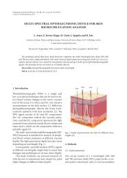
A photoplethysmography device for multipurpose blood circulatory ...
A photoplethysmography device for multipurpose blood circulatory ...
A photoplethysmography device for multipurpose blood circulatory ...

You also want an ePaper? Increase the reach of your titles
YUMPU automatically turns print PDFs into web optimized ePapers that Google loves.
A <strong>photoplethysmography</strong> <strong>device</strong> <strong>for</strong> <strong>multipurpose</strong> <strong>blood</strong> <strong>circulatory</strong><br />
system assessment<br />
E. Kviesis-Kipge, J. Zaharans, O. Rubenis, A. Grabovskis<br />
Bio-optics and Fiberoptics Laboratory, Institute of Atomic Physics and Spectroscopy,<br />
University of Latvia, Riga, Latvia<br />
e-mail: cobba@inbox.lv<br />
ABSTRACT<br />
A novel method <strong>for</strong> <strong>photoplethysmography</strong> (PPG) signal detection has been proposed and implemented in a three channel<br />
prototype <strong>device</strong>. The current design is simple, low cost and does not require sophisticated analogue circuits. The<br />
prototype was evaluated by physiological measurements and recorded PPG signals from conduit arteries of human subject.<br />
1. INTRODUCTION<br />
Photoplethysmography (PPG) [1] is an optical, non-invasive measuring technique that provides immediate diagnostic<br />
in<strong>for</strong>mation on the cardiovascular state. PPG signals reflect the change in <strong>blood</strong> volume caused by <strong>blood</strong> vessel expansion<br />
and contraction, which can be detected by a photodiode if external light is illuminated into the tissue. Time intervals<br />
between the PPG peaks can be converted into the heart rate or pulse, but the wave<strong>for</strong>m characteristics of each individual<br />
PPG pulse contain hemodynamic in<strong>for</strong>mation. There are two types of PPG sensors: reflection and remission. The first<br />
one consists of an infrared LED and photodiode that are both located on the same side of the PPG sensor, but in the remission<br />
sensor design, they are separated. By using the reflection type sensor it is possible to detect <strong>blood</strong> pulsations<br />
from ~ 1 – 3 mm deep under the skin’s surface. The PPG signal consists of two components- a slow, varying DC offset<br />
representing the skin: <strong>blood</strong> volume in the probe-covered area, and a fast, alternating AC component that reflects the<br />
<strong>blood</strong> volume pulsations. The amplitude of the AC-component is only 0,5 – 4% of the DC offset in a PPG signal.<br />
Dynamics of <strong>blood</strong> transport in the human vascular system can be monitored at various body locations with relatively<br />
simple and convenient, optical PPG contact probes. The PPG technique has good potential <strong>for</strong> express diagnostics and<br />
early screening of cardiovascular pathologies, as well as <strong>for</strong> scientific research (physiological measurements) and selfmonitoring<br />
of vascular conditions [2].<br />
There are commercially available PPG <strong>device</strong>s, but those are based on the standard remission <strong>photoplethysmography</strong>,<br />
which limits their use - signal can be measured only from finger, ear, and small sides of body where infrared radiation<br />
can pass through. However, reflection PPG sensors are necessary in the determination of the properties of the arteries<br />
and <strong>blood</strong> circulation dynamics.<br />
Photoplethysmography successfully can be used in physiological measurements and supplement ultrasound, ECG, and<br />
other methods. Physiological measurements require an accurate and easy to use PPG signal measuring <strong>device</strong> that ensures<br />
low signal noise and high spatial and temporal resolution (at least 1 kHz). Such <strong>device</strong>s are not produced commercially,<br />
so a custom-made prototype was developed.<br />
The main problem is that the conventional PPG <strong>device</strong>s are technologically complicated. Usually these <strong>device</strong>s contain<br />
an expensive analogue to digital converter, low noise operational amplifiers, and other complex hardware. These increase<br />
manufacturing costs and time <strong>for</strong> the end product. A simple, low cost <strong>photoplethysmography</strong> signal capturing<br />
<strong>device</strong> can be designed with using only two transistors, a photodiode, and a microcontroller.<br />
The goal of this work was to develop and to test a new precise measuring <strong>device</strong>, which can be used <strong>for</strong> scientific research<br />
purposes. This article describes a <strong>photoplethysmography</strong> measurement system based on the measurements of the<br />
discharge time of the photodiode [3]. The discharge time is proportional to the amount of light detected by the photodi-<br />
Novel Biophotonic Techniques and Applications, edited by Henricus J. C. M. Sterenborg, I. Alex Vitkin, Proc. of SPIE-OSA<br />
Biomedical Optics, SPIE Vol. 8090, 80900W · © 2011 SPIE-OSA · CCC code: 1605-7422/11/$18 · doi: 10.1117/12.889654<br />
SPIE-OSA/ Vol. 8090 80900W-1<br />
Downloaded from SPIE Digital Library on 22 Jun 2012 to 85.254.232.1. Terms of Use: http://spiedl.org/terms
ode. The result is the PPG signal shape can be quickly restored digitally without the standard ADC-conversion. The<br />
equipment novelties are the abandonment from the standard sensors, the equipment design simplicity, and the digital<br />
signal directly in the PPG sensor.<br />
2. METHOD AND EQUIPMENT<br />
A new approach to capture PPG signal used a 32-bit timer built in the central processor. LED emitted 30-microsecond<br />
radiation pulses that periodically discharged the photodiode and the discharge time was captured by a microcontroller<br />
after each pulse. The PPG signal was restored by measuring the discharge time of the photodiode with a following CPU -<br />
processing [4]. Analog amplifiers and filters as well as their noise can be avoided this way. The captured data were sent<br />
to computer with further data processing, imaging and storage.<br />
The parameters that can be measured with this <strong>device</strong> are the pulse shape of the <strong>photoplethysmography</strong> signal and the<br />
signal delay time, if two or three senor probes are used. The sensors are placed on the extremities at different locations<br />
and then the acquired signals’ time shifts are compared. Pulse transit time can be calculated by software in real time or<br />
post processing. This gives useful in<strong>for</strong>mation about the patient’s cardiovascular condition and arterial occlusions [5].<br />
Calculations are necessary to pinpoint the PPG signal "footprint" or minimum. In turn, this means that the signal cannot<br />
be filtered because the filter changes the signal shape and makes a phase shift.<br />
Our developed set up consists of: a PPG sensor, a <strong>photoplethysmography</strong> capture system - control unit and a Li-ion accumulator.<br />
The scheme’s design is based on the photodiode discharge time measurement using a 32-bit timer built into<br />
the microcontroller. A special reflection PPG sensor probe was created and adapted to the artery measurement specifics,<br />
and provided the possibility to take contact PPG measurements virtually from any site of the body.<br />
In general, this <strong>device</strong> was built to capture high resolution, low noise <strong>photoplethysmography</strong> signal from arteries. The<br />
equipment was designed <strong>for</strong> stationary use when patient is in recumbence with no movement and was tested in collaboration<br />
with colleagues from the Department of Human and Animal Physiology in the Faculty of Biology at the University<br />
of Latvia.<br />
2.1. Design of the <strong>device</strong><br />
This prototype is a custom made 3-channel digital PPG <strong>device</strong> with a sampling rate: 1 kHz per channel, 875 nm LED,<br />
and photodiodes with a daylight filter and peak spectral response wavelength of 880nm. Originally this <strong>device</strong> was designed<br />
<strong>for</strong> scientific purposes, which require an analog signal output to one common data acquisition system. There<strong>for</strong>e,<br />
the digital PPG signals were converted using a built in 12-bit eight-channel digital-to-analog converter (TLV5610). The<br />
block diagram of the equipment is shown in Figure 1.<br />
The <strong>device</strong> had an integrated LED driver which provided stable power throughout the battery’s discharge range. LEDs<br />
were driven by 55 ± 15 mA (5 mA stepping), so that no perceptible warming of the upper tissue layer was produced.<br />
Three channels of DAC were used to regulate the LED current.<br />
An important improvement was the use of a solid state digital field transistor which was physically close to the photodiode.<br />
In this case, it was necessary to place the sensor ~ 1 – 1,5 m away from the measuring unit. Thus, the impact of the<br />
movements during the measurements would cause PPG signal to be corrupted. The key novelty was the absence of analog<br />
amplifiers, filters, and capacitors in the signal input circuit.<br />
SPIE-OSA/ Vol. 8090 80900W-2<br />
Downloaded from SPIE Digital Library on 22 Jun 2012 to 85.254.232.1. Terms of Use: http://spiedl.org/terms
Figure 1. Block diagram of the <strong>device</strong>.<br />
The only filter integrated in the design was a digital second order Butterworth low pass filter with the cut off frequency<br />
of 42Hz @ 3dB. This filter did not distort the <strong>photoplethysmography</strong> signal shape and phase because the typical bandwidth<br />
of the PPG signal is 0,05 – 40Hz. The measured noise level of the <strong>device</strong> was -30 to -40dB compared to the PPG<br />
signal level. The true physiological noise was considered as a signal recorded from sensor placed on the skin with completely<br />
occluded <strong>blood</strong> circulation.<br />
The time was captured in the hardware and there<strong>for</strong>e, did not require software resources. The appliance stored the data<br />
using a 255 point FIR digital filter. It removed noise from the electrical network and ambient light. It is important to<br />
mention, that this filter worked in real time with a known constant time delay to the actual signal. To obtain specific data<br />
<strong>for</strong> further analysis, the filter could be disabled with the push of a button.<br />
The <strong>device</strong> dimensions are 90 x 47 x 145 mm, weight 300 grams, one 2x16 character liquid crystal display, with three<br />
rotary encoder and push buttons which are shown in Figure 2. The sensors are connected using three DE9 9-pin D-sub<br />
RS232 connectors. The outputs are 3 gold-plated RCA jacks. The signal output is single ended 0 – 5V. The <strong>device</strong> has<br />
ten discrete digital gain levels.<br />
Figure 2. Complete measuring <strong>device</strong>.<br />
SPIE-OSA/ Vol. 8090 80900W-3<br />
Downloaded from SPIE Digital Library on 22 Jun 2012 to 85.254.232.1. Terms of Use: http://spiedl.org/terms
2.2. Sensor construction<br />
Three custom-made, reflection type PPG probes were created and adapted to meet criteria necessary <strong>for</strong> the measurements<br />
of arterial <strong>blood</strong> pulsations from the skin over the conduit artery. The PPG method is very sensitive to tissue<br />
movement and to the sensor-to-tissue contact <strong>for</strong>ce. There<strong>for</strong>e, to prevent signal artifacts, the arterial PPG sensors were<br />
fastened with custom-made holders.<br />
Figure 3. Photoplethysmography sensor.<br />
The sensor is built on a small PCB that contains an electronic circuit shown in Figure 4. The entire sensors dimensions<br />
are 10x15x8 mm. LED is the only element in the sensor which consumes a lot of power 30 – 50mA (depending on the<br />
place where the sensor is located on the patient’s body).<br />
A selected silicon PIN photodiode OSRAM - BPW34-FA - with daylight filter and the active surface area of 7mm 2 and<br />
the peak spectral response wavelength of 880nm was used. A SMD type of an infrared radiant diode model which is<br />
SIR91-21C/F7 was used with a peak wavelength of 875 nm, a transmission angle of 20°, and a diameter of 1,9 mm. A<br />
sensor’s housing material is cured polyurethane sealant, which is especially suitable <strong>for</strong> mounting the electronic circuit<br />
components. A special screening barrier <strong>for</strong> the photodiode was made within the sensor to lower the influence of ambient<br />
light. A barrier is located between the LED and the photodiode and is 5mm from the edge of sensors end (darker vertical<br />
line Figure 3).<br />
In the sensors, there is an integrated signal conversion scheme (Fig. 4). The PPG method uses N-channel transistors that<br />
are digital FET. The transistor Q2 charges the capacitor C15 and a photodiode with a supply voltage of +3,3V. While Q1<br />
converts the signal level from analog to digital, the resistor R12 is a pull-down resistor that discharges capacitor C15 and<br />
diode D4. R10 is a pull-up resistor, so that the cable length connecting the sensor to the main circuit board is almost<br />
irrelevant because of the transmitted logic levels of +3,3V.<br />
Figure 4. Electronic circuit of the sensor.<br />
Figure 5. Digital PPG wave<strong>for</strong>m captured with oscilloscope<br />
(TDS2002B).<br />
The added capacitor C15 with a capacity of 1nF is parallel to the photodiode D4. The photodiode capacity following the<br />
manufacturer's specifications is 72pF, which is little compared to the C15 that acts as ballast. If the duration of the discharge<br />
is prolonged, this will increase the signal amplitude, but reduce the sample rate. The discharge time is fixed to<br />
1ms, which corresponds to the 1000 measurements per second that is considered as more than enough <strong>for</strong> the PPG measurements<br />
and analysis. Capacitor C15 and photodiode D4 are charged with the clock frequency of 1 kHz. The capacitor<br />
SPIE-OSA/ Vol. 8090 80900W-4<br />
Downloaded from SPIE Digital Library on 22 Jun 2012 to 85.254.232.1. Terms of Use: http://spiedl.org/terms
charging time is constant - 30us (lower wave<strong>for</strong>m Figure 5). The tests were per<strong>for</strong>med with different charging times and<br />
the minimum required to charge the 1nF capacitor was discovered. After each charging cycle, the discharge takes place,<br />
which is measured and depending on the photodiode, the incident radiation intensity is also measured.<br />
Using this measuring technique, one must consider that the more light that photodiode D4 captures, the quicker capacitor<br />
C15 discharges and results a signal with lower resolution. And vice versa situation if less light fall on photodiode D4,<br />
capacitor C15 discharges slowly, and if there is no light, the whole process is stopped. This effect is considered as a<br />
disadvantage, because if a signal from deeper tissue layers is desired, usually the LED brightness is increased. However,<br />
if that is done with this measuring technique, the signal amplitude decreases. The only solution is to adjust the value of<br />
capacitor C15 to achieve the required resolution. A lower capacitor value is suitable <strong>for</strong> small and shallow <strong>blood</strong> vessels,<br />
and a larger value <strong>for</strong> deeper vessels. Capacitors are matched experimentally, depending on measurement methodology<br />
and the needs of researcher.<br />
In general, the capacitor discharge is an exponential curve (Figure 6); the <strong>device</strong> had a sampling rate of 1 KHz, which is<br />
fast enough to consider each captured time interval is a linear discharge.<br />
Figure 6. Digital PPG capacitor discharge curve.<br />
The only condition <strong>for</strong> the <strong>device</strong> to fully operate and to gain analyzing PPG signals with a resolution of 1ms is to use a<br />
high-speed microcontroller. The <strong>device</strong> design uses NXP LPC2148 ARM7, which works at 48MHz clock frequency.<br />
Also, a micro-timer built-in capture module was used to automatically maintain the capacitor discharge time value. One<br />
measurement composes a single point on the time-axis and the PPG signal is restored by an accumulation of such points.<br />
The software code was written in C with an optimization of the sleep time that resulted in minimal power consumption<br />
~15mA@48MHz (only <strong>for</strong> CPU).<br />
Each volunteer was subjected to three five minute measurement series. During the experiment, a subject was held in a<br />
supine position on an ergonomic pedestal at room temperature (24°C) in quiet and com<strong>for</strong>table conditions. Prior to data<br />
recording, the PPG sensors were placed while the subject adapted. The volunteers were cautioned not to intake any caffeine<br />
or eat a meal within 2 hours be<strong>for</strong>e the experiment.<br />
3. RESULTS OF THE MEASUREMENTS<br />
High quality <strong>photoplethysmography</strong> signals were acquired by using the proposed technique and <strong>device</strong>. The <strong>device</strong> was<br />
used in parametric studies of the leg arteries. High demands on the signal to noise ratio ensured clean PPG signals from a<br />
single artery. The requirement <strong>for</strong> equipment error was to be less than fluctuations in the physiological parameters. It was<br />
essential that the <strong>device</strong> did not introduce additional errors.<br />
18 to 26 years old volunteers (2 males, 4 females) with a healthy lifestyle and a body mass index range of 16,2<br />
to 25,9 kg/m 2 and no signs or symptoms of cardiovascular diseases gave their in<strong>for</strong>med consent to participate. The Scien-<br />
SPIE-OSA/ Vol. 8090 80900W-5<br />
Downloaded from SPIE Digital Library on 22 Jun 2012 to 85.254.232.1. Terms of Use: http://spiedl.org/terms
tific Research Ethics Committee of the University of Latvia, Institute of Experimental and Clinical Medicine approved<br />
the research protocol.<br />
Photoplethysmography sensors were placed as follows: over popliteal artery in the popliteal fossa, over posterior tibial<br />
artery near the ankle and on leg’s big toe. Distances between sensors were noted to derive the pulse wave velocities from<br />
the pulse transit time – delay time of the pulse wave reached all three PPG sensors consecutively.<br />
Results of the measurements are illustrated in Figure 7A and comparisons of the previous digital PPG <strong>device</strong> outputs are<br />
presented in Figure 7B. Acquired PPG signal is considered as a significant improvement of the method, <strong>device</strong> and<br />
equipment. The signal had low noise and directly outputted from the <strong>device</strong> without post processing on a PC. Resolution<br />
is high <strong>for</strong> further analysis and conclusions about the arteries. The best PPG signal amplitudes corresponded to decay<br />
times of about 800 – 1500 us (AC component of the <strong>photoplethysmography</strong> signal), and is considered as very good result.<br />
CPU timer capture runs at 48MHz, so that the mean PPG signal is about 1/48 from the whole scale and is ~2% of<br />
the DC component.<br />
2800<br />
Big toe<br />
Ankle<br />
Popliteal fossa<br />
2600<br />
2400<br />
Original PPG signal<br />
Digitaly smoothed signal<br />
2200<br />
1000<br />
Decay Time, us<br />
2000<br />
1800<br />
1600<br />
1400<br />
1200<br />
1000<br />
800<br />
600<br />
400<br />
1260 1261 1262 1263 1264 1265 1266 1267<br />
Time, s<br />
Decay Time, uS<br />
900<br />
800<br />
700<br />
600<br />
500<br />
400<br />
300<br />
200<br />
100<br />
0<br />
0 1 2 3 4 5<br />
Time, s<br />
A<br />
B<br />
Figure 7. Photoplethysmography signals measured within the infrared spectrum (875 nm). A - Shows signal captured with the improved<br />
methodology and <strong>device</strong>. The wave<strong>for</strong>m is original, unfiltered, and directly outputted from the <strong>device</strong>, B - represents a signal<br />
output from the earlier <strong>device</strong> (from finger) [4].<br />
Sensors were placed on the skin over the conduit arteries. Pulse transit time also was measured and analyzed because of<br />
<strong>device</strong>’s high resolution of 1ms. Since physiology measurements require several <strong>device</strong>s, like PPG, ECG, pressure monitoring,<br />
ultrasound, and sphygmogram, they must be connected to one common data acquisition module – in other words,<br />
it is necessary that the entire system is driven by the same clock. The analog signals from the developed PPG <strong>device</strong> and<br />
a Finometer (beat per beat pressure monitoring) were captured simultaneously by a 12-bit ADC USB data acquisition<br />
module at 1 kHz per channel, and stored in a PC. Later, a PPG signal was processed offline with custom developed<br />
Matlab software (signal smoothing with wavelet and Savitsky-Golay filters to reduce signal artifacts and ADC stepping<br />
noise). Foot-to-foot pulse wave transit time and wave<strong>for</strong>m second derivative parameters were computed <strong>for</strong> each PPG<br />
signal in a beat per beat manner.<br />
4. CONCLUSIONS<br />
A new method and equipment <strong>for</strong> acquiring <strong>photoplethysmography</strong> signals were developed and successfully tested. The<br />
<strong>device</strong> showed good measurements and accuracy sufficient <strong>for</strong> PPG scientific research. The sampling rate of 1 KHz<br />
seems to be enough <strong>for</strong> the <strong>photoplethysmography</strong> signal shape characterization. The digital signal already in the sensor<br />
SPIE-OSA/ Vol. 8090 80900W-6<br />
Downloaded from SPIE Digital Library on 22 Jun 2012 to 85.254.232.1. Terms of Use: http://spiedl.org/terms
(using only two transistors) is a way to transmit low level PPG signal <strong>for</strong> about two meters without inducting additional<br />
noise. This approach does not require any expensive operation amplifiers, low noise power supply, analog multiplexors<br />
or ADC.<br />
Equipment advantages are the low noise, low power, low weight, the digital PPG signal in the sensor, and professionally<br />
produced remission PPG sensor, as well as there is no need <strong>for</strong> <strong>device</strong> calibration and high tolerance resistors. The method<br />
is inexpensive, easy to build and particularly appropriate <strong>for</strong> small, low cost, portable <strong>device</strong>s – <strong>for</strong> example, integrating<br />
it into a garment (smart clothes). By using this method, it is easy to create a <strong>device</strong> that measures PPG signals at<br />
different wavelengths of radiant diodes, i.e., multispectral <strong>device</strong> with a one perceptive photodiode [6].<br />
However, setting up the sensors <strong>for</strong> measurement from the arteries requires special skills. Also, a screening barrier and a<br />
photodiode with daylight filter are essential. The main disadvantage of this PPG signal capture <strong>device</strong> is the capacitor<br />
discharge dependence on light intensity. To resolve this, fast capture and separate sensors <strong>for</strong> capturing PPG signals from<br />
various sites of the body can be an option. When using this approach, only remission PPG sensors can be used because<br />
transmission <strong>photoplethysmography</strong> signal is too weak to reach the threshold of photodiode discharge level.<br />
ACKNOWLEDGMENTS<br />
The financial support of the European Social Fund (grant #2009/0211/1DP/1.1.1.2.0/09/APIA/VIAA/077) is highly<br />
appreciated.<br />
REFERENCES<br />
[1] J. Allen, “Photoplethysmography and its application in clinical physiological measurement”, Physiol. Meas. Vol. 28, p. 1-39<br />
(2007).<br />
[2] Spigulis J., “Optical non-invasive monitoring of skin <strong>blood</strong> pulsations”, Appl. Opt., 44, 1850-1857 (2005).<br />
[3] R. Stojanovic, D. Karadaglic, “A LED–LED-based <strong>photoplethysmography</strong> sensor”, Physiol. Meas. Vol. 28, p. 19-27 (2007).<br />
[4] Kviesis-Kipge E., “A new technique <strong>for</strong> optical detection of biosignals”, Latv. J. Phys. Tehn. Sci., N3, Vol. 46, p. 64 – 69<br />
(2009).<br />
[5] R. Erts, J. Spigulis, I. Kukulis and M. Ozols, “Bilateral <strong>photoplethysmography</strong> studies of the leg arterial stenosis”, Physiol.<br />
Meas. Vol. 26, p. 865-874 (2005).<br />
[6] L. Asare, “Multi-spectral <strong>photoplethysmography</strong> biosensor”, Proc. SPIE Vol. 8073A (2011).<br />
SPIE-OSA/ Vol. 8090 80900W-7<br />
Downloaded from SPIE Digital Library on 22 Jun 2012 to 85.254.232.1. Terms of Use: http://spiedl.org/terms