Digital Frequency Discriminators - Akon, Inc.
Digital Frequency Discriminators - Akon, Inc.
Digital Frequency Discriminators - Akon, Inc.

Create successful ePaper yourself
Turn your PDF publications into a flip-book with our unique Google optimized e-Paper software.
Table of Contents<br />
.................................................................................................................<br />
General<br />
4 Mission Statement<br />
4 Our Team<br />
4 Our Commitment<br />
5 Facilities<br />
5 Engineering<br />
6 Manufacturing<br />
7 Quality Assurance<br />
8 Environmental Stress Screening<br />
8 High-Rel and Space-Rel Screening Options<br />
9 Major Programs Supplied<br />
Components<br />
.................................................................................................................<br />
10 Power Dividers/Equalizers<br />
Datasheet 115: Miniature Power Dividers/Combiners<br />
Datasheet 116: Miniature Fixed Gain Equalizers (Negative Slope)<br />
Datasheet 301: Wideband Equalizer, 0.5-18 GHz<br />
15 <strong>Digital</strong> Phase Shifters<br />
Datasheet 300: X-Band Phase Shifter, 8.0-8.4 GHz<br />
18 <strong>Digital</strong>ly Controlled Attenuators<br />
Datasheet 242: <strong>Digital</strong>ly Controlled Attenuator, 1.0-18.0 GHz<br />
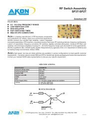
21 Switches<br />
Datasheet 259: SP2T Switch<br />
Datasheet 252: SP5T Switch<br />
Datasheet 258: SP3T-SP2T Switch Assembly<br />
28 Band Pass Filters<br />
Datasheet 267: Bandpass Filter, 2.0-6.0 GHz<br />
Datasheet 268: Bandpass Filter, 6.0-10.0 GHz<br />
Datasheet 269: Bandpass Filter, 10.0-11.0 GHz<br />
Datasheet 270: Bandpass Filter, 12.0 GHz<br />
Datasheet 271: Bandpass Filter, 10.0-14.0 GHz<br />
Datasheet 272: Bandpass Filter, 14.0-18.0 GHz<br />
35 Log Components<br />
Datasheet 121C: Fast Rise & Fall Time, 2.0-18.0 GHz, 60dB SDLA<br />
Datasheet 123A: Fast Rise & Fall Time 75dB ERDLVA 0.5 - 2.0 GHz<br />
Datasheet 124A: 46dB Dynamic Range DLVA<br />
Datasheet 134C: Fast Rise & Fall Time, 75dB ERDLVA<br />
Datasheet 303: High Speed SDLAs<br />
Datasheet 136: High Speed SDLAs with Limited RF Output<br />
2135 Ringwood Ave. • San Jose, CA 95131 • Tel. (408) 432-8039 • Fax (408) 432-1089<br />
www.akoninc.com • sales@akoninc.com<br />
2
Table of Contents<br />
..............................................................................................................<br />
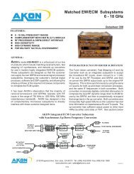
Integrated Microwave Assemblies and Subsystems<br />
4 Tuners<br />
Datasheet 285: Downconverter, 2-6 GHz to 1-2 GHz Baseband<br />
Datasheet 302: Downconverter 6-18 GHz to 2-6 Ghz Baseband<br />
Datasheet 306: 0.8-20 GHz Pre-Channelized Dual Conversion Selectable<br />
IF Bandwidth Miniature Receiver<br />
Datasheet 239: Wideband Microwave Assembly, 0.5-18.0 GHz<br />
Datasheet 203: Microwave Assembly, 1.0-18.0 GHz<br />
Datasheet 146: 0.4-18 GHz Pre-Channelized SIngle Conversion, IF B.W.<br />
2.0-6.0 GHz Miniature Receiver<br />
6Fast Stepping LO Assemblies<br />
Datasheet 275: LO Assembly<br />
Datasheet 238: LO Assembly with BITE Source<br />
hreat Simulator RF Sources<br />
Datasheet 231: Threat Simulator RF Source, 6.0-18.0 GHz<br />
Datasheet 233: Threat Simulator RF Source, 0.5-18.0 GHz<br />
<br />
Switch Matrices<br />
Datasheet 236: Switching Matrix, 6.0-18.0 GHz<br />
Datasheet 237: Switching Matrix, 2.0-18.0 GHz<br />
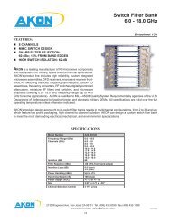
3ilter Banks and Switch Filter Banks<br />
Datasheet 151: Switch Filter Bank, 6.0-18.0 GHz<br />
<br />
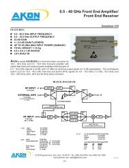
Receiver Subsystems<br />
Datasheet 294: Five Channel Channelized Receiver, 1.0-18.0 GHz<br />
atasheet 173: Phase Matched Receiver for Interferometer DF Systems,<br />
2.0-8.0, 8.0-18.0 GHz<br />
Datasheet 174: Integrated ECM Receiver Subassembly 6.0-18.0 GHz<br />
91 <strong>Digital</strong> <strong>Frequency</strong> <strong>Discriminators</strong><br />
Datasheet 297: <strong>Digital</strong> <strong>Frequency</strong> Discriminator, 2.0-6.0 GHz<br />
Datasheet 298: <strong>Digital</strong> <strong>Frequency</strong> Discriminator, 6.0-18.0 GHz<br />
Datasheet 299: <strong>Digital</strong> <strong>Frequency</strong> Discriminator, 2.0-18.0 GHz<br />
Datasheet 295: <strong>Digital</strong> <strong>Frequency</strong> Discriminator, 239-386 MHz<br />
Datasheet 251: <strong>Digital</strong> <strong>Frequency</strong> Discriminator, 4.3- 5.3 GHz<br />
105 Glossary of Terms- Logging Products<br />
112 Glossary of Terms- Tuners<br />
2135 Ringwood Ave. • San Jose, CA 95131 • Tel. (408) 432-8039 • Fax (408) 432-1089<br />
www.akoninc.com • sales@akoninc.com<br />
3
Mission Statement<br />
AKON’s mission is to fulfill our customers’ requirements for<br />
the highest quality RF/Microwave components and subsystems<br />
by focusing on all aspects of product performance,<br />
reliability, delivery and competitive price.<br />
Our Team<br />
AKON is composed of highly skilled individuals dedicated to<br />
working in unison to produce a “built-in quality” product and<br />
to provide the best customer service possible. <strong>Akon</strong> encourages<br />
creativity, growth, and improvement from every member<br />
of its team.<br />
Our Commitment<br />
Excellence:<br />
Integrity:<br />
Teamwork:<br />
Responsibility:<br />
We are committed to providing the highest levels of customer service and<br />
satisfaction through continuous improvement of our facilities, personnel and products.<br />
We are committed to the highest standards of ethics, integrity and professionalism.<br />
We value teamwork and effective communications by and between our<br />
company, our customers, our employees and our suppliers.<br />
We act responsibly toward our community and our environment.<br />
2135 Ringwood Ave. • San Jose, CA 95131 • Tel. (408) 432-8039 • Fax (408) 432-1089<br />
www.akoninc.com • sales@akoninc.com<br />
4
Facilities<br />
AKON, <strong>Inc</strong>. is located in San Jose, California, in the heart<br />
of Silicon Valley and less than ten minutes by car from<br />
San Jose International Airport (SJC). It is comprised of<br />
approximately 45,000 square feet of state-of-the-art manufacturing,<br />
engineering design, and general offi ce space.<br />
The manufacturing and testing area is designed and maintained<br />
to simulate an advanced development laboratory-type<br />
environment. It is an enclosed area that is environmentally<br />
controlled with respect to airborne particles, temperature,<br />
humidity, air fl ow patterns, air motion, and lighting. We<br />
have built an ESD-protected raised fl oor underneath and<br />
overhead an air-fi ltration system keeps air circulating to<br />
a better than Class 100,000 level. All employees must<br />
be properly gowned with protective hair and shoe coverings<br />
to prevent unnecessary contamination of the area.<br />
Being a U.S. government cleared facility, AKON’s facility as a whole is a tight security area with badge access<br />
only. Security cameras are placed throughout the building to protect us and our customers. All departments<br />
are themselves independent security areas - with card access given only to department employees.<br />
Engineering<br />
In its 28 years in business, AKON has built up a reputation<br />
of engineering design excellence that is evident in every unit<br />
that is shipped. For more than a quarter century, AKON’s<br />
engineering team has focused solely on designing, developing,<br />
and maintaining the highest quality RF/microwave subsystems<br />
and components for the electronic warfare community. AKON<br />
designs and fabricates hardware for airborne, seaboard and<br />
space applications ranging from log components to major subsystems.<br />
In support of its design activities, AKON has established separately managed in-house laboratories<br />
2135 Ringwood Ave. • San Jose, CA 95131 • Tel. (408) 432-8039 • Fax (408) 432-1089<br />
www.akoninc.com • sales@akoninc.com<br />
5
for the design and development of components such as, for example, miniature switches and fi lters.<br />
These laboratories design components specifi c to customer requirements and signifi cantly reduce<br />
prototype development times by eliminating long lead-times associated with procurement from outside<br />
vendors and allows for real-time feedback on component performance and modifi cations, when<br />
necessary.<br />
AKON engineers have the knowledge, tools and experience<br />
to design, manage and deliver even the most technically<br />
challenging projects. Their experience includes all aspects<br />
of the product design and development life cycle: research<br />
and development design and analysis, fabrication and<br />
manufacturing and maintenance and diagnostics.<br />
Design analysis using computer-based simulation and<br />
modeling programs provide an assessment of each design’s<br />
reliability, reproducibility, testability, and maintainability.<br />
Simulation software reduces the time and costs required to perform circuit analyses while modeling<br />
allows identifi cation and correction of design problems before the circuit is prototyped.<br />
All engineering work is subject to AKON’s 100% Quality Assurance Procedures and a dedicated document<br />
control department to ensure full project documentation with complete traceability available to<br />
the customer.<br />
Manufacturing<br />
AKON’s considerable manufacturing capability<br />
is the result of combining state of the art<br />
facilities and equipment with multi-talented<br />
personnel at all levels with a procurement and<br />
manufacturing strategy that maximizes value<br />
to our customers.<br />
All AKON units are assembled, tuned and<br />
tested by experienced and highly skilled individuals.<br />
Each employee plays an important<br />
role in the continuous improvement and quality enhancement of our products and our manufacturing<br />
lines are structured in a way that reduces set-up times and maximizes fi rst-time quality.<br />
2135 Ringwood Ave. • San Jose, CA 95131 • Tel. (408) 432-8039 • Fax (408) 432-1089<br />
www.akoninc.com • sales@akoninc.com<br />
6
Close relationships between all employees- from<br />
line-level personnel to management- is encouraged<br />
to facilitate communication and to guarantee realtime<br />
and unifi ed action by the organization.<br />
Our procurement strategy is similarly focused on<br />
maximizing value to our customers by bringing inhouse<br />
the manufacture of key components- fi lters,<br />
switches, digitally controlled attenuators, amplifiers,<br />
etc. - which traditionally are procured from outside<br />
vendors. This minimizes the impacts caused by<br />
late supplier delivery, component quality issues<br />
and unexpectedly high material cost. For items we<br />
do procure, our close relationships with suppliers<br />
contribute to lower costs and higher quality as suppliers deliver parts as they are needed. Procured<br />
components are subjected to rigorous inspection and testing prior to sending to manufacturing fl oor.<br />
Quality Assurance<br />
AKON considers quality a major element of product<br />
and management performance. Its quality<br />
system conforms to MIL-I-45208. Requirements<br />
beyond this, including elements of MIL-STD-883<br />
and MIL-I-38510, are common but are applied to<br />
specific customer contracts. Receiving Inspection<br />
of all incoming material conformance to the purchase<br />
order and <strong>Akon</strong> drawings and specifications<br />
is performed. In-process quality inspections are<br />
performed at the completion of housing assembly,<br />
pre-tune, pre-cap, and fi nal assembly and testing stages. To further ensure the best possible quality,<br />
in-process monitoring of the manufacturing process is conducted on an ongoing random basis.<br />
2135 Ringwood Ave. • San Jose, CA 95131 • Tel. (408) 432-8039 • Fax (408) 432-1089<br />
www.akoninc.com • sales@akoninc.com<br />
7
Environmental Stress Screening (ESS)<br />
AKON has a fully instrumented environmental testing laboratory. MIL-STD-167, MIL-STD-202,<br />
MIL-STD-750, MIL-STD-810, and MIL-STD-883 are the basis of most tests. Following is list of<br />
commonly performed testing at <strong>Akon</strong>.<br />
Stabilization Bake<br />
Thermal Shock<br />
Mechanical Shock<br />
Vibration<br />
Thermovac<br />
Temperature-Humidity<br />
Temperature Cycling<br />
DC Burn-In<br />
RF Burn-In<br />
Leak Rate Testing<br />
Microprocessor Controlled +125°C.<br />
Air to Air. Microprocessor Controlled. Temperatures: -54°C or -65°C to +125°C<br />
(typ). Soak Times: 30-60 mins.<br />
Drop Machine: 50 G, 11 ms, 1/2 sine wave. 100 G, 6 ms, 1/2 sine wave1500<br />
G, 1/2 ms, 1/2 sine wave. Shaker Shock<br />
Random, Sine, and combined Random/Sine. 2,200 force pounds.<br />
Microprocessor controlled. Thermal platform temperature range:-54°C to<br />
+95°C.<br />
Microprocessor controlled. Temperatures to +95°C. Relative humidity of 5% to<br />
95%.<br />
Microprocessor controlled. DC power application at any point within the program.<br />
RF power application.<br />
Microprocessor controlled. Temperatures to +95°C.<br />
Microprocessor controlled.Temperatures to +95°C.<br />
Hermetic Packages: Helium Fine Leak Rate Testing to 1 x 10⁻¹⁰ ATM cm3/s.<br />
Gross Leak Testing.<br />
Non-Hermetic Packages: Bubble Leak Testing.<br />
High Rel and Space Rel Screening Options<br />
AKON’s design and construction techniques set the standard<br />
for rugged construction and long operating life. It has<br />
developed a high-reliability capability to serve its customers’<br />
growing needs for space qualifi ed high reliability microwave<br />
products and the necessary controls and processes to supply<br />
this demanding customer segment have been put in place to<br />
insure the highest quality product. Many space level screening<br />
and qualifi cation testing procedures can be performed<br />
in-house, along with the necessary documentation control,<br />
program management, and process tracking to keep any high<br />
reliability project on track Data is kept on fi le for vibration, mechanical shock, temperature cycling,<br />
life tests and electrical tests over temperature. Additional test data is also available for package related<br />
tests such as water vapor content and hermeticity. Test methods used are from MIL-STD-883,<br />
MIL-STD-810, and MIL-STD-202.<br />
2135 Ringwood Ave. • San Jose, CA 95131 • Tel. (408) 432-8039 • Fax (408) 432-1089<br />
www.akoninc.com • sales@akoninc.com<br />
8
Major Programs Supplied by AKON<br />
Alenia (Italy) - EFA<br />
AEG -Germany FL-1800<br />
Anaren - Canadian Fighter<br />
CSIST - Shipboard Radar Update<br />
Ford - Harm Seeker<br />
India Govt. - Aircraft Radar<br />
ITT - IDECM Advanced ECM<br />
Japan - FSX, Several RWR Programs<br />
JPL-MLS (complex Converter Assy.)<br />
JPL-MIRO (complex IMA)<br />
Litton - A12 Carrier Stealth Aircraft<br />
Loral - ALQ-131<br />
Loral - ALR-56C (F-15 Fighter)<br />
Loral - ALR-56M (F-16 Fighter)<br />
Marconi (UK) - Airborne Programs<br />
Raytheon - ALQ-142<br />
Raytheon - SLQ-32<br />
Raytheon-ULQ-18<br />
Sanders-USM-406C<br />
Sanders-USM-464<br />
USN PMR -Range Radar<br />
BAE/MiKES - SPEWS II F-16 RWR<br />
NRL- HGHS<br />
Westinghouse - ASPJ Multi-Platform<br />
U.S. Navy - SLQ-32<br />
Raytheon/Envisioneering - SeaRAM Program<br />
<strong>Akon</strong> <strong>Inc</strong>. has delivered in excess of 75,000 units for these programs.<br />
2135 Ringwood Ave. • San Jose, CA 95131 • Tel. (408) 432-8039 • Fax (408) 432-1089<br />
www.akoninc.com • sales@akoninc.com<br />
9
Power Dividers/Equalizers<br />
offers miniature power<br />
dividers and gain (slope) equalizers covering<br />
the frequency range of 1.0 to 18.0<br />
GHz. These units can be provided in<br />
connectorized or drop-in packages.<br />
2135 Ringwood Ave. • San Jose, CA 95131 • Tel. (408) 432-8039 • Fax (408) 432-1089<br />
www.akoninc.com • sales@akoninc.com<br />
10
Miniature Power Dividers<br />
& Power Combiners<br />
FEATURES:<br />
Datasheet 115<br />
•COMPACT SIZE<br />
•COAXIAL AND DROP-IN CONFIGURATIONS<br />
•2.0-18.0 GHz FREQUENCY RANGE<br />
•HERMETIC PACKAGE OPTIONS<br />
•LOW INSERTION LOSS<br />
•EXCELLENT PHASE AND AMPLITUDE TRACKING<br />
•SIZE: 0.87” x 0.95” x 0.22”<br />
AKON is a leading manufacturer of RF/microwave components and<br />
subsystems for military, space and commercial applications. <strong>Akon</strong>’s<br />
product line includes high reliability, custom integrated microwave<br />
assemblies, DFD receivers, microwave receiver front-ends, RF<br />
switching matrices, frequency synthesizers, custom LO assemblies, frequency converters, RF switches, digitally controlled<br />
attenuators, phase shifters, miniature RF filters and switches, and microwave amplifiers covering the 0.5-18.0 GHz<br />
frequency range (up to 40.0 GHz for some applications). <strong>Akon</strong> is qualifi ed to MIL-I-45208 Quality System Requirements<br />
by agencies of the U.S. Department of Defense and by leading foreign and domestic military OEMs. All specifi cations<br />
are valid over the full operating temperature unless otherwise indicated.<br />
AKON’s product line of power dividers and power combiners operate over the 0.5-18.0 GHz frequency band with inherent<br />
thin fi lm reliability. Models are available with optimized performance over 2.0-6.0 GHz and 6.0-18.0 GHz bands in<br />
either coaxial or drop-in packages. Optional hermetic packaging is also available. SMA connectors are fi eld replaceable<br />
and removable. Units exhibit excellent optional phase and amplitude tracking.<br />
SPECIFICATIONS:<br />
Model Number PCS-2060 PCS-6018 PCS-2018<br />
<strong>Frequency</strong> Range (GHz) 2.0-6.0 6.0-18.0 2.0-18.0<br />
Insertion Loss (dB) 1.0 1.2 1.8<br />
<strong>Frequency</strong> Flatness (dB) +/-0.30 (max) +/-0.50 (max) +/-1.00 (max)<br />
Isolation (dB) 15 (min) 15 (min) 15 (min)<br />
VSWR 1.8:1 (max) 1.8:1 (max) 2.0:1 (max)<br />
Amplitude Balance (dB) +/-0.2 (nom) +/-0.3 (nom) +/-0.4 (nom)<br />
Phase Balance (º) +/-4.0 (nom) +/-7.0 (nom) +/-10.0 (nom)<br />
2135 Ringwood Ave. • San Jose, CA 95131 • Tel. (408) 432-8039 • Fax (408) 432-1089<br />
www.akoninc.com • sales@akoninc.com<br />
DS115 REVF<br />
11
Miniature Power Dividers<br />
& Power Combiners<br />
OUTLINE DRAWING:<br />
Datasheet 115<br />
2135 Ringwood Ave. • San Jose, CA 95131 • Tel. (408) 432-8039 • Fax (408) 432-1089<br />
www.akoninc.com • sales@akoninc.com<br />
12<br />
DS115 REVF
Miniature Fixed Gain Equalizers<br />
(Negative Slope)<br />
FEATURES:<br />
•SMALL SIZE<br />
•2.0-18.0 GHz FREQUENCY RANGE<br />
•LOW VSWR AND LOSS<br />
•THIN FILM RELIABILITY<br />
•WIDE SELECTION OF ATTENUATION SLOPES<br />
•SIZE: 1.095” x 0.67” x 0.22”<br />
Datasheet 116<br />
AKON is a leading manufacturer of RF/microwave components<br />
MODEL GEX-2018-N1<br />
and subsystems for military, space and commercial applications.<br />
<strong>Akon</strong>’s product line includes high reliability custom integrated microwave<br />
assemblies, DIFM receivers, microwave receiver front-ends, RF switching matrices, frequency synthesizers, custom<br />
LO assemblies, frequency converters, RF switches, digitally controlled attenuators, miniature RF fi lters and switches,<br />
and microwave amplifi ers covering 0.5-18.0 GHz frequency range (up to 40.0 GHz for some applications). <strong>Akon</strong> is qualifi<br />
ed to MIL-I-45208 Quality System Requirements by agencies of the US Department of Defense and by leading foreign<br />
and domestic military OEMs. All specifi cations are valid over the full operating temperature unless otherwise indicated.<br />
AKON’s miniature fi xed slope gain equalizers cover the full 0.5-18.0 GHz frequency range with a wide variety of attenuation<br />
slopes. Units are of thin fi lm construction and utilize proven passive and absorptive designs resulting in excellent<br />
reliability. Units are available in drop-in confi gurations. Coaxial models feature SMA fi eld replaceable connectors which<br />
can be removed for stripline applications. Optional in-house screening to MIL-STD-883 is available.<br />
SPECIFICATIONS:<br />
Model Number GEX-2018-N1 GEX-2018-N2 GEX-2018-N3 GEX-2018-N4 GEX-2018-N5 GEX-2018-N6<br />
<strong>Frequency</strong> Range (GHz) 2.0-18.0 2.0-18.0 2.0-18.0 2.0-18.0 2.0-18.0 2.0-18.0<br />
Insertion Loss (dB) 7.0 @2 GHz<br />
3.0 @18 GHz<br />
6.5 @2 GHz<br />
3.0 @18 GHz<br />
6.0 @2 GHz<br />
3.0 @18 GHz<br />
5.5 @2 GHz<br />
2.5 @18 GHz<br />
5.0 @2 GHz<br />
2.5 @18 GHz<br />
4.5 @2 GHz<br />
2.0 @18 GHz<br />
Ripple (dB) +/-0.75 (max) +/-0.75 (max) +/-0.75 (max) +/-0.50 (max) +/-0.50 (max) +/-0.50 (max)<br />
Slope (dB/GHz) 0.25 (nom) 0.22 (nom) 0.19 (nom) 0.19 (nom) 0.16 (nom) 0.16 (nom)<br />
VSWR 2:0:1 2:0:1 2:0:1 2:0:1 2:0:1 2:0:1<br />
OUTLINE DRAWING:<br />
PERFORMANCE CHARACTERISTICS:<br />
2X 0.098<br />
SMA MALE<br />
CONNECTOR<br />
J1<br />
AKON<br />
5V234<br />
MODEL GEX-2018-N1<br />
J2<br />
S/N_____<br />
D/C_____<br />
MADE IN<br />
U.S.A.<br />
2135 Ringwood Ave. • San Jose, CA 95131 • Tel. (408) 432-8039 • Fax (408) 432-1089<br />
www.akoninc.com • sales@akoninc.com<br />
13<br />
DS116 REVE
Wideband Equalizer<br />
0.5-18 GHz<br />
FEATURES:<br />
Datasheet 301<br />
•0.5-18.0 GHz FREQUENCY RANGE<br />
•QUALIFIED TO MIL-STD-810F<br />
•EXTENDED TEMPERATURE RANGE<br />
•EXCELLENT GAIN FLATNESS<br />
•LOW RIPPLE<br />
•2.0:1 VSWR<br />
•SIZE: 1.09” x 0.67” x 0.22”<br />
MODEL GEX-2018-N7<br />
AKON is a leading manufacturer of RF/microwave components<br />
and subsystems for military, space and commercial applications.<br />
<strong>Akon</strong>’s product line includes high reliability, custom integrated microwave assemblies, DFD receivers, microwave receiver<br />
front-ends, RF switching matrices, frequency synthesizers, custom LO assemblies, frequency converters, RF switches,<br />
digitally controlled attenuators, phase shifters, miniature RF fi lters and switches, and microwave amplifi ers covering the<br />
0.5-18.0 GHz frequency range (up to 40.0 GHz for some applications). <strong>Akon</strong> is qualifi ed to MIL-I-45208 Quality System<br />
Requirements by agencies of the U.S. Department of Defense and by leading foreign and domestic military OEMs. All<br />
specifi cations are valid over the full operating temperature unless otherwise indicated.<br />
AKON’s wideband equalizers are of thin fi lm construction and utilize proven passive and absorptive designs resulting in<br />
excellent reliability. Units are available in drop-in confi gurations. Coaxial models feature SMA fi eld replaceable connectors<br />
which can be removed for stripline applications. Optional in-house screening to MIL-STD-883 is available.<br />
Model Number<br />
GEX-2018-N7<br />
<strong>Frequency</strong> Range (GHz) 0.5-18.0<br />
Insertion loss (dB)<br />
Ripple (dB)<br />
VSWR<br />
Slope (dB/GHz)<br />
13 @ 0.5 GHz (max)<br />
2 @ 18 GHz (max)<br />
±0.5 (max)<br />
2.0:1 max<br />
0.625 (nom)<br />
Temperature Range (°C) -40 to +71<br />
SPECIFICATIONS:<br />
OUTLINE DRAWING:<br />
SMA MALE<br />
CONNECTOR<br />
J1<br />
AKON<br />
5V234<br />
MODEL GEX-2018-N7<br />
J2<br />
S/N_____<br />
D/C_____<br />
MADE IN<br />
U.S.A.<br />
2135 Ringwood Ave. • San Jose, CA 95131 • Tel. (408) 432-8039 • Fax (408) 432-1089<br />
www.akoninc.com • sales@akoninc.com<br />
14<br />
DS301 REVD
<strong>Digital</strong>ly Controlled Phase Shifters<br />
offers a line of digitally<br />
controlled RF phase shifters that operate<br />
over the band of 2.0 to 18.0 GHz, providing<br />
up to 360º of phase shift relative to<br />
insertion phase. Phase adjustment resolution<br />
can be as high as 6 bits. Phase<br />
shift speeds are on the order of 500 nS.<br />
Possible applications include phased arrays,<br />
solid-state frequency serrodyning,<br />
phase and vector modulators and amplifier<br />
feedback linearizers.<br />
2135 Ringwood Ave. • San Jose, CA 95131 • Tel. (408) 432-8039 • Fax (408) 432-1089<br />
www.akoninc.com • sales@akoninc.com<br />
15
X-Band Phase Shifter<br />
8.0-8.4 GHz<br />
FEATURES:<br />
•8.0-8.4 GHz FREQUENCY RANGE<br />
•HIGH RELIABILITY<br />
•20 dB POWER GAIN<br />
•EXCELLENT GAIN FLATNESS<br />
•LOW INSERTION LOSS<br />
•4 DEGREES PHASE ACCURACY<br />
•SIZE: 3.0” x 2.5” x 0.79<br />
Datasheet 300<br />
AKON is a leading manufacturer of RF/microwave components and<br />
subsystems for military, space and commercial applications. <strong>Akon</strong>’s<br />
product line includes high reliability, custom integrated microwave<br />
assemblies, DFD receivers, microwave receiver front-ends, RF<br />
MODEL A50-8X003<br />
switching matrices, frequency synthesizers, custom LO assemblies,<br />
frequency converters, RF switches, digitally controlled attenuators, phase shifters, miniature RF fi lters and switches, and<br />
microwave amplifi ers covering the 0.5-18.0 GHz frequency range (up to 40.0 GHz for some applications). <strong>Akon</strong> is qualifi<br />
ed to MIL-I-45208 Quality System Requirements by agencies of the U.S. Department of Defense and by leading foreign<br />
and domestic military OEMs. All specifi cations are valid over the full operating temperature unless otherwise indicated.<br />
AKON’s X-Band Band Phase Shifter, Model Number A50-8X003 can be offered as a total hermetic unit. The design<br />
approach used in this unit is fi eld proven and uses a series of amplifi ers, a 5 bit phase shifter, a four throw switch (SP4T)<br />
and four medium power amplifi ers.<br />
Model Number<br />
A50-8X003<br />
<strong>Frequency</strong> (GHz) 8.0-8.4<br />
Output Power (dBm)<br />
Power Gain (dB)<br />
SPECIFICATIONS:<br />
+20 @ 1 dB compression for all conditions<br />
20 (typical)<br />
Gain Flatness (dB) ± 0.5<br />
Gain Variation (dB)<br />
± 0.5 (max)(over frequency/operating temp)<br />
IM product level (dB)<br />
20 down (min)(@ 1 dB compression)<br />
VSWR<br />
1.5:1 (typical)<br />
Phase Shift Range (°) 360<br />
Phase Shift Control (bits) 5<br />
Phase Linearity<br />
Linear over 8.0 to 8.4 GHz<br />
Phase Accuracy (° RMS) 4<br />
Harmonics(dBc)<br />
-20 (typical)<br />
Spurious (dBc) -50<br />
Power Supply (VDC)<br />
+6.5 @ 660 mA; -6.5 @ 75 mA<br />
Package<br />
Hermetic<br />
Temperature Range (°C) -15 to +60<br />
Size (inches) 3.0” x 2.5" x 0.79"<br />
2135 Ringwood Ave. • San Jose, CA 95131 • Tel. (408) 432-8039 • Fax (408) 432-1089<br />
www.akoninc.com • sales@akoninc.com<br />
16<br />
DS300 REVB
X-Band Phase Shifter<br />
8.0-8.4 GHz<br />
Datasheet 300<br />
BLOCK DIAGRAM:<br />
RF OUT<br />
RF IN<br />
6 BITS<br />
S<br />
P<br />
4<br />
T<br />
RF OUT<br />
RF OUT<br />
RF OUT<br />
OUTLINE DRAWING:<br />
<br />
<br />
<br />
<br />
<br />
<br />
<br />
<br />
<br />
<br />
<br />
<br />
<br />
<br />
<br />
<br />
<br />
<br />
<br />
<br />
<br />
<br />
<br />
<br />
<br />
<br />
<br />
<br />
<br />
<br />
<br />
2135 Ringwood Ave. • San Jose, CA 95131 • Tel. (408) 432-8039 • Fax (408) 432-1089<br />
www.akoninc.com • sales@akoninc.com<br />
17<br />
DS300 REVB
<strong>Digital</strong>ly Controlled Attenuators<br />
offers a line of digitally<br />
controlled RF attenuators that operate<br />
over the range of 1.0 to 20.0 GHz and<br />
can provide attenuation up to 60 dB. Attenuation<br />
is fl at over the entire band with<br />
no suck-outs and remains relatively fl at<br />
regardless of attenuation setting. Control<br />
is single-ended TTL with up to 8 bits<br />
of resolution. Response time is typically<br />
under 100 nS.<br />
2135 Ringwood Ave. • San Jose, CA 95131 • Tel. (408) 432-8039 • Fax (408) 432-1089<br />
www.akoninc.com • sales@akoninc.com<br />
18
<strong>Digital</strong>ly Controlled Attenuator<br />
1.0-18.0 GHz<br />
FEATURES:<br />
•1.0-18.0 GHz FREQUENCY RANGE<br />
•TTL COMPATIBLE LOGIC<br />
•HIGH SPEED SWITCHING<br />
•LOW DC POWER CONSUMPTION<br />
•STABLE ATTENUATION<br />
•HIGH RF POWER HANDLING<br />
•SIZE: 2” x 2” x 0.45”<br />
Datasheet 242<br />
AKON is a leading manufacturer of RF/microwave components and<br />
subsystems for military, space and commercial applications. <strong>Akon</strong>’s<br />
product line includes high reliability, custom integrated microwave<br />
assemblies, DFD receivers, microwave receiver front-ends, RF<br />
switching matrices, frequency synthesizers, custom LO assemblies,<br />
MODEL A50-MH009<br />
frequency converters, RF switches, digitally controlled attenuators,<br />
miniature RF fi lters and switches, and microwave amplifi ers covering 0.5-18.0 GHz frequency range (up to 40.0 GHz<br />
for some applications). <strong>Akon</strong> is qualifi ed to MIL-I-45208 Quality System Requirements by agencies of the U.S. Department<br />
of Defense and by leading foreign and domestic military OEMs. All specifi cations are valid over the full operating<br />
temperature unless otherwise indicated.<br />
SPECIFICATIONS:<br />
Model Number<br />
A50-MH009<br />
<strong>Frequency</strong> Range (GHz) 1.0-18.0<br />
Attenuation Range (dB) +5 to +65<br />
Attenuation Step Size (dB) 0.3<br />
<strong>Digital</strong> Control<br />
TTL Logic Control; 8 bit<br />
Insertion Loss (dB)<br />
5.0 (nom)<br />
Attenuation Linearity (dB)<br />
+/-1.0 (nom)<br />
Attenuation Flatness (dB)<br />
+/-2.0 (max)<br />
Power Handling (dBm)<br />
+20 CW (operating)<br />
Switching Speed (nS)<br />
650 (max)<br />
VSWR<br />
2.2:1 (max)<br />
Impedance (Ohms) 50<br />
RF Connectors<br />
SMA-F<br />
Control and Power Supply Connector<br />
D-Type<br />
Power Supply (VDC) +12, -12V<br />
Size 2” x 2” x 0.455”<br />
Operating Temperature (°C) -40 to +71<br />
2135 Ringwood Ave. • San Jose, CA 95131 • Tel. (408) 432-8039 • Fax (408) 432-1089<br />
www.akoninc.com • sales@akoninc.com<br />
19<br />
DS242 REVD
<strong>Digital</strong>ly Controlled Attenuator<br />
1.0-18.0 GHz<br />
Datasheet 242<br />
OUTLINE DRAWING:<br />
<br />
<br />
<br />
<br />
<br />
<br />
<br />
J3<br />
CONTROL<br />
<br />
<br />
<br />
J1 input<br />
5V234<br />
, inc<br />
DIGITAL ATTENUATOR<br />
Model: A50-MH009<br />
Ser No.______<br />
D.Code______<br />
<br />
<br />
J2 output<br />
<br />
AREA = 1.465 in<br />
2<br />
TYPICAL PERFORMANCE:<br />
ATTENUATION RESPONSE @25ºC<br />
ATTENUATION (dB)<br />
0<br />
-10<br />
-20<br />
-30<br />
-40<br />
-50<br />
-60<br />
2.0 6.0 10.0 14.0 18.0<br />
FREQUENCY (GHz)<br />
2135 Ringwood Ave. • San Jose, CA 95131 • Tel. (408) 432-8039 • Fax (408) 432-1089<br />
www.akoninc.com • sales@akoninc.com<br />
DS242 REVD<br />
20
Switches<br />
offers a line of high performance,<br />
high speed and high isolation<br />
RF switches. These switches are available<br />
in standard confi gurations such as<br />
SPST through SP8T, as well as in nearly<br />
any custom confi guration the customer<br />
can imagine. Switching speeds are typically<br />
on the order of 100 nanoseconds, but<br />
higher speed units, to under 10 nanoseconds<br />
are also optionally available. Switch<br />
off state isolation can be 60 db or greater,<br />
or a standard 30 to 35 dB. Both reflective<br />
and absorptive confi gurations are available.<br />
<strong>Frequency</strong> band coverage is model<br />
dependent but ranges from 500 MHz to<br />
40 GHz. Connector options include SMA,<br />
GPO, TNC, type N or an extended pin for<br />
drop-in. Standard control logic is single<br />
ended TTL. Industry standard housings<br />
are available or custom packaging and<br />
integrated switching assemblies as well.<br />
2135 Ringwood Ave. • San Jose, CA 95131 • Tel. (408) 432-8039 • Fax (408) 432-1089<br />
www.akoninc.com • sales@akoninc.com<br />
21
RF Switch<br />
SP2T (with silent arm)<br />
FEATURES:<br />
•2.0-18.0 GHz FREQUENCY RANGE<br />
•LOW INSERTION LOSS<br />
•HIGH ISOLATION<br />
•FAST SWITCHING TIMES<br />
•SMA OR GPO CONNECTORS<br />
Datasheet 259<br />
AKON is a leading manufacturer of RF/microwave components<br />
and subsystems for military, space and commercial applications.<br />
<strong>Akon</strong>’s product line includes high reliability, custom integrated<br />
microwave assemblies, DFD receivers, microwave receiver frontends,<br />
RF switching matrices, frequency synthesizers, custom LO MODEL A35-MH139<br />
assemblies, frequency converters, RF switches, digitally controlled<br />
attenuators, miniature RF fi lters and switches, and microwave amplifi ers covering 0.5-18.0 GHz frequency range (up<br />
to 40.0 GHz for some applications). <strong>Akon</strong> is qualifi ed to MIL-I-45208 Quality System Requirements by agencies of the<br />
U.S. Department of Defense and by leading foreign and domestic military OEMs.<br />
AKON’s high speed, low loss pin diode switches are available in various confi gurations to meet specifi c customer requirements.<br />
Connector options include SMA and GPO to handle high density packaging and lowest loss requirements.<br />
Contact your nearest AKON sales representative to discuss your specifi c requirement.<br />
SPECIFICATIONS:<br />
Model Number<br />
A35-MH139<br />
<strong>Frequency</strong> Range (GHz) 2.0-18.0<br />
Switching Speed (nS)<br />
100 (typ)<br />
Isolation (dB)<br />
60 (typ)<br />
Insertion Loss (dB)<br />
3 (max)<br />
VSWR<br />
2.0:1 (max)<br />
Type<br />
Refl ective<br />
Power Supply (VDC) +/-12<br />
J1<br />
RF IN<br />
J2<br />
RF IN<br />
BLOCK DIAGRAM:<br />
DESCRETE<br />
LIMITER<br />
LIMITER<br />
LIMITER<br />
1.8 dB @18 GHz<br />
3.0 dB @18 GHz<br />
50 Ω<br />
SILENT ARM<br />
J0<br />
DESCRETE<br />
SP3T<br />
DESCRETE COMBINATION:<br />
5.0 – 6.0 dB<br />
VSWR INTERACTION<br />
OUTLINE DRAWING:<br />
S/N _____<br />
J0<br />
D/C _____<br />
J2<br />
A35-MH139<br />
5V234<br />
-V L2 L1 +5V GND<br />
J1<br />
2135 Ringwood Ave. • San Jose, CA 95131 • Tel. (408) 432-8039 • Fax (408) 432-1089<br />
www.akoninc.com • sales@akoninc.com<br />
22<br />
DS259 REVE
RF Switch<br />
SP2T (with silent arm)<br />
Datasheet 259<br />
TYPICAL PERFORMANCE:<br />
J 0 - J 1<br />
LOG MAGNITUDE REF= 0.000 dB 12.000 dB/DIV<br />
INSERTION LOSS<br />
ISOLATION<br />
0.500000000 GHz 18.5000000<br />
J 0 - J 2<br />
2<br />
CH1: A -M -2.41 dB<br />
2.0 dB/ REF 0.00 dB<br />
CH4: B -M +1.090 SWR<br />
1.00 / REF 2.000 SWR<br />
1<br />
INSERTION LOSS<br />
5<br />
-2.3 dB<br />
4<br />
2<br />
VSWR<br />
5<br />
STRT 1.00000 GHz MKR 18.0000 GHz STOP 18.5000 GHz<br />
2135 Ringwood Ave. • San Jose, CA 95131 • Tel. (408) 432-8039 • Fax (408) 432-1089<br />
www.akoninc.com • sales@akoninc.com<br />
23<br />
DS259 REVE
RF Switch<br />
SP5T<br />
FEATURES:<br />
•2.0-18.0 GHz FREQUENCY RANGE<br />
•LOW INSERTION LOSS<br />
•HIGH ISOLATION<br />
•FAST SWITCHING TIME<br />
•SMA OR GPO CONNECTORS<br />
Datasheet 252<br />
AKON is a leading manufacturer of RF/microwave components<br />
and subsystems for military, space and commercial applications.<br />
<strong>Akon</strong>’s product line includes high reliability, custom<br />
integrated microwave assemblies, DFD receivers, microwave<br />
receiver front-ends, RF switching matrices, frequency synthesizers,<br />
custom LO assemblies, frequency converters, RF<br />
MODEL A35-MH137<br />
switches, digitally controlled attenuators, miniature RF fi lters and switches, and microwave amplifi ers covering 0.5-18.0<br />
GHz frequency range (up to 40.0 GHz for some applications). <strong>Akon</strong> is qualifi ed to MIL-I-45208 Quality System Requirements<br />
by agencies of the U.S. Department of Defense and by leading foreign and domestic military OEMs.<br />
AKON’s high speed, low loss pin diode switches are available in various confi gurations to meet specifi c customer requirements.<br />
Connector options include SMA and GPO to handle high density packaging and lowest loss requirements.<br />
Contact your nearest AKON sales representative to discuss your specifi c requirement.<br />
SPECIFICATIONS:<br />
BLOCK DIAGRAM:<br />
Model Number<br />
A35-MH137<br />
<strong>Frequency</strong> Range (GHz) 2.0-18.0<br />
Switching Speed (nS)<br />
50 (typ)<br />
Isolation (dB)<br />
60 (typ)<br />
Insertion Loss (dB)<br />
3 (max)<br />
VSWR<br />
2.0:1 (max)<br />
Type<br />
Refl ective<br />
Power Supply (VDC) +/-12<br />
OUTLINE DRAWING:<br />
GND<br />
A0<br />
A1<br />
EN<br />
J2<br />
D/C____<br />
J1<br />
J3<br />
5V234<br />
AKON<br />
A35-MH137<br />
J0<br />
J4<br />
S/N____<br />
J5<br />
GND<br />
A2<br />
-5V<br />
+5V<br />
2135 Ringwood Ave. • San Jose, CA 95131 • Tel. (408) 432-8039 • Fax (408) 432-1089<br />
www.akoninc.com • sales@akoninc.com<br />
24<br />
DS252 REVD
RF Switch<br />
SP5T<br />
Datasheet 252<br />
TYPICAL PERFORMANCE:<br />
LOG MAGNITUDE REF= 0.000 dB 10.000 dB/DIV<br />
J 0 - J 1<br />
INSERTION LOSS<br />
J 0 - J 2<br />
INSERTION LOSS<br />
LOG MAGNITUDE REF= 0.000 dB 10.000 dB/DIV<br />
ISOLATION<br />
0.500000000 GHz 18.500000000<br />
ISOLATION<br />
0.500000000 GHz 18.500000000<br />
LOG MAGNITUDE REF= 0.000 dB 10.000 dB/DIV<br />
J 0 - J 3<br />
INSERTION LOSS<br />
J 0 - J 4<br />
INSERTION LOSS<br />
LOG MAGNITUDE REF= 0.000 dB 10.000 dB/DIV<br />
ISOLATION<br />
ISOLATION<br />
0.500000000 GHz 18.500000000<br />
0.500000000 GHz 18.500000000<br />
LOG MAGNITUDE REF= 0.000 dB 10.000 dB/DIV<br />
J 0 - J 5<br />
INSERTION LOSS<br />
J 0 - J 5<br />
12 ><br />
CH1: A -M CH2: A -M<br />
2.0 dB/ REF 2.0 dB/ REF 0.00 dB 0.00 dB<br />
CH3: B -M CH4: B -M<br />
1.0 / REF 1.00 / REF 2.000 SWR 2.000 SWR<br />
INSERTION LOSS<br />
VSWR<br />
34 ><br />
ISOLATION<br />
0.500000000 GHz 18.500000000<br />
STRT 1.000 GHz<br />
STOP 18.5000 GHz<br />
2135 Ringwood Ave. • San Jose, CA 95131 • Tel. (408) 432-8039 • Fax (408) 432-1089<br />
www.akoninc.com • sales@akoninc.com<br />
25<br />
DS252 REVD
RF Switch<br />
SP3T-SP2T<br />
FEATURES:<br />
•2.0-18.0 GHz FREQUENCY RANGE<br />
•LOW INSERTION LOSS<br />
•HIGH ISOLATION<br />
•FAST SWITCHING TIMES<br />
•SMA OR GPO CONNECTORS<br />
Datasheet 258<br />
AKON is a leading manufacturer of RF/microwave components<br />
and subsystems for military, space and commercial applications.<br />
<strong>Akon</strong>’s product line includes high reliability, custom<br />
integrated microwave assemblies, DFD receivers, microwave<br />
receiver front-ends, RF switching matrices, frequency synthesizers,<br />
custom LO assemblies, frequency converters, RF<br />
MODEL A35-MH138<br />
switches, digitally controlled attenuators, miniature RF fi lters and switches, and microwave amplifi ers covering 0.5-18.0<br />
GHz frequency range (up to 40.0 GHz for some applications). <strong>Akon</strong> is qualifi ed to MIL-I-45208 Quality System Requirements<br />
by agencies of the U.S. Department of Defense and by leading foreign and domestic military OEMs.<br />
AKON’s high speed, low loss pin diode switches are available in various confi gurations to meet specifi c customer requirements.<br />
Connector options include SMA and GPO to handle high density packaging and lowest loss requirements.<br />
Contact your nearest AKON sales representative to discuss your specifi c requirement.<br />
SPECIFICATIONS:<br />
BLOCK DIAGRAM:<br />
Model Number<br />
A35-MH138<br />
<strong>Frequency</strong> Range (GHz) 2.0-18.0<br />
Switching Speed (nS)<br />
50 (typ)<br />
Isolation (dB)<br />
60 (typ)<br />
Insertion Loss (dB)<br />
3 (max)<br />
VSWR<br />
2.0:1 (max)<br />
Type<br />
Refl ective<br />
Power Supply (VDC) +/-12<br />
J1<br />
RF IN<br />
J2<br />
RF IN<br />
LIMITER<br />
SW1 SW2<br />
SILENT ARM<br />
LIMITER<br />
50 Ω<br />
DESCRETE COMBINATIONS<br />
LIMITER: 1.8 dB<br />
SW1: 3.0 dB<br />
8.0 dB<br />
SW2: 3.0 dB<br />
J3<br />
J4<br />
OUTLINE DRAWING:<br />
J2<br />
-5V<br />
L1<br />
L2<br />
S/N _____<br />
J1<br />
J3<br />
A35-MH138<br />
5V234<br />
L3<br />
GND<br />
L4<br />
+5V<br />
D/C _____<br />
J4<br />
2135 Ringwood Ave. • San Jose, CA 95131 • Tel. (408) 432-8039 • Fax (408) 432-1089<br />
www.akoninc.com • sales@akoninc.com<br />
26<br />
DS258 REVE
RF Switch<br />
SP3T-SP2T<br />
Datasheet 258<br />
TYPICAL PERFORMANCE:<br />
TYPICAL “ON” J 1<br />
-J 4<br />
“OFF” J 1<br />
-J 3<br />
LOG MAGNITUDE REF= 0.000 dB 12.000 dB/DIV<br />
INSERTION LOSS<br />
ISOLATION<br />
0.500000000 GHz 18.5000000<br />
TYPICAL J 1<br />
-J 4<br />
CH1: A -M CH2: A -M<br />
2.0 dB/ REF 0.00 dB 2.0 dB/ REF 0.00 dB<br />
CH3: B -M CH4: B -M<br />
1.0 / REF 2.000 SWR 1.00 / REF 2.000 SWR<br />
12 ><br />
INSERTION LOSS<br />
-3.5 dB<br />
34 ><br />
VSWR<br />
STRT 800.000 MHz<br />
STOP 18.3000 GHz<br />
2135 Ringwood Ave. • San Jose, CA 95131 • Tel. (408) 432-8039 • Fax (408) 432-1089<br />
www.akoninc.com • sales@akoninc.com<br />
27<br />
DS258 REVE
Band Pass Filters<br />
is a worldwide leader in<br />
the design and manufacture of custom<br />
band pass filters. Low cost, custom fi lters<br />
are available in prototypes to production<br />
quantities with high performance,<br />
low loss designs. A full range of technologies<br />
is available for a wide variety<br />
of commercial and military applications.<br />
2135 Ringwood Ave. • San Jose, CA 95131 • Tel. (408) 432-8039 • Fax (408) 432-1089<br />
www.akoninc.com • sales@akoninc.com<br />
28
Band Pass Filter<br />
2.0-6.0 GHz<br />
FEATURES:<br />
•COMPACT/LIGHTWEIGHT PACKAGE SIZE<br />
•HIGH SELECTIVITY<br />
•LOW INSERTION LOSS<br />
•CUSTOMIZABLE PACKAGING<br />
•EXCELLENT TEMPERATURE STABILITY<br />
•OPTIONAL GPO CONNECTOR<br />
•SIZE: 2.9” x 0.7” x 0.488”<br />
Datasheet 267<br />
AKON is a leading manufacturer RF/microwave components<br />
and subsystems for military, space and commercial<br />
applications. Our compact fi lters are available in<br />
all topologies for Low Pass, High Pass, Band Pass and<br />
MODEL A65-MH005<br />
Band Reject requirements. Filters are all custom specifi<br />
ed per individual customer requirements. Please provide all necessary information and specifi cations for frequency<br />
breakpoints, skirt sharpness, passband ripple and loss, VSWR, power handling and operating temperature range.<br />
SPECIFICATIONS:<br />
Model Number<br />
A65-MH005<br />
Pass Band (GHz) 2.0-6.0<br />
Insertion Loss (dB)<br />
2.5 (max)<br />
VSWR<br />
2.0:1 (max) Passband<br />
Stop Band (dB)<br />
60 (min)<br />
Power Handling (dBm)<br />
+37 (max)<br />
Size 2.9” x 0.7” x 0.488”<br />
OUTLINE DRAWING:<br />
AKON, <strong>Inc</strong> .<br />
A65-MH005<br />
SER NO.______<br />
D.CODE_____<br />
TYPICAL PERFORMANCE:<br />
LOG MAGNITUDE REF= 0.000 dB 10.000 dB/DIV<br />
1.000625000 GHz 7.998125000<br />
FREQUENCY RESPONSE<br />
STRT 1.00000 GHz<br />
INSERTION/RETURN LOSS<br />
STOP 8.00000 GHz<br />
2135 Ringwood Ave. • San Jose, CA 95131 • Tel. (408) 432-8039 • Fax (408) 432-1089<br />
www.akoninc.com • sales@akoninc.com<br />
29<br />
DS267 REVC
Band Pass Filter<br />
6.0-10.0 GHz<br />
FEATURES:<br />
•COMPACT/LIGHTWEIGHT PACKAGE SIZE<br />
•HIGH SELECTIVITY<br />
•LOW INSERTION LOSS<br />
•CUSTOMIZABLE PACKAGING<br />
•EXCELLENT TEMPERATURE STABILITY<br />
•OPTIONAL GPO CONNECTOR<br />
•SIZE: 2.9” x 0.58” x 0.50”<br />
Datasheet 268<br />
AKON is a leading manufacturer RF/microwave components<br />
and subsystems for military, space and commercial<br />
applications. Our compact fi lters are available in<br />
all topologies for Low Pass, High Pass, Band Pass and<br />
MODEL A65-MH002<br />
Band Reject requirements. Filters are all custom specifi<br />
ed per individual customer requirements. Please provide all necessary information and specifi cations for frequency<br />
breakpoints, skirt sharpness, passband ripple and loss, VSWR, power handling and operating temperature range.<br />
SPECIFICATIONS:<br />
Model Number<br />
A65-MH002<br />
Pass Band (GHz) 6.0-10.0<br />
Insertion Loss (dB)<br />
1.0 (max)<br />
VSWR<br />
2.0:1 (max) Passband<br />
Stop Band (dB)<br />
-70 (min)<br />
Power Handling (dBm)<br />
+40 (max)<br />
Size 2.9” x 0.58” x 0.50”<br />
OUTLINE DRAWING:<br />
AKON, <strong>Inc</strong>.<br />
A65-MH002<br />
SERNO._____<br />
D.CODE______<br />
TYPICAL PERFORMANCE:<br />
LOG MAGNITUDE REF= 0.000 dB 10.000 dB/DIV<br />
2.0000 GHz 14.015000000<br />
FREQUENCY RESPONSE<br />
STRT 4.50000 GHz<br />
INSERTION/RETURN LOSS<br />
STOP 11.50000 GHz<br />
2135 Ringwood Ave. • San Jose, CA 95131 • Tel. (408) 432-8039 • Fax (408) 432-1089<br />
www.akoninc.com • sales@akoninc.com<br />
30<br />
DS268 REVC
Band Pass Filter<br />
10.0-11.0 GHz<br />
FEATURES:<br />
•COMPACT/LIGHTWEIGHT PACKAGE SIZE<br />
•HIGH SELECTIVITY<br />
•LOW INSERTION LOSS<br />
•CUSTOMIZABLE PACKAGING<br />
•EXCELLENT TEMPERATURE STABILITY<br />
•OPTIONAL GPO CONNECTOR<br />
•SIZE: 2.25” x 0.60” x 0.38”<br />
Datasheet 269<br />
AKON is a leading manufacturer RF/microwave components<br />
and subsystems for military, space and commercial<br />
applications. Our compact fi lters are available in<br />
all topologies for Low Pass, High Pass, Band Pass and<br />
MODEL A65-MH012<br />
Band Reject requirements. Filters are all custom specifi<br />
ed per individual customer requirements. Please provide all necessary information and specifi cations for frequency<br />
breakpoints, skirt sharpness, passband ripple and loss, VSWR, power handling and operating temperature range.<br />
SPECIFICATIONS:<br />
Model Number<br />
A65-MH012<br />
Pass Band (GHz) 10.0-11.0<br />
Insertion Loss (dB)<br />
1.0 (max)<br />
VSWR<br />
2.0:1 (max) Passband<br />
Stop Band (dB)<br />
-65 (min)<br />
Power Handling (dBm)<br />
+40 (max)<br />
Size 2.25” x 0.60” x 0.38”<br />
OUTLINE DRAWING:<br />
AKON, <strong>Inc</strong>.<br />
A65-MH012<br />
SERNO.______<br />
D.CODE______<br />
TYPICAL PERFORMANCE:<br />
LOG 10 dB/REF -30 dB<br />
START 8.0000 GHz<br />
STOP 13.00000000 GHz<br />
STRT 9.436000 GHz<br />
STOP 11.66500 GHz<br />
FREQUENCY RESPONSE<br />
INSERTION/RETURN LOSS<br />
2135 Ringwood Ave. • San Jose, CA 95131 • Tel. (408) 432-8039 • Fax (408) 432-1089<br />
www.akoninc.com • sales@akoninc.com<br />
31<br />
DS269 REVC
Band Pass Filter<br />
12.0 GHz<br />
FEATURES:<br />
•COMPACT/LIGHTWEIGHT PACKAGE SIZE<br />
•HIGH SELECTIVITY<br />
•LOW INSERTION LOSS<br />
•CUSTOMIZABLE PACKAGING<br />
•EXCELLENT TEMPERATURE STABILITY<br />
•OPTIONAL GPO CONNECTOR<br />
•SIZE: 2.25” x 0.63” x 0.38”<br />
Datasheet 270<br />
AKON is a leading manufacturer RF/microwave components<br />
and subsystems for military, space and commercial<br />
applications. Our compact fi lters are available in<br />
all topologies for Low Pass, High Pass, Band Pass and<br />
MODEL A65-MH011<br />
Band Reject requirements. Filters are all custom specifi<br />
ed per individual customer requirements. Please provide all necessary information and specifi cations for frequency<br />
breakpoints, skirt sharpness, passband ripple and loss, VSWR, power handling and operating temperature range.<br />
SPECIFICATIONS:<br />
Model Number<br />
A65-MH011<br />
Passband (GHz) 12.0<br />
Insertion Loss (dB)<br />
1.8 (max)<br />
VSWR<br />
1.5:1 (max) Passband<br />
Stopband (dB)<br />
-70 (min)<br />
Power Handling (dBm)<br />
+40 (max)<br />
Size 2.25” x 0.63” x 0.38”<br />
OUTLINE DRAWING:<br />
AKON, inc<br />
A65-MH011<br />
SERNO.______<br />
D.CODE______<br />
TYPICAL PERFORMANCE:<br />
LOG 10 dB/REF -30 dB<br />
CH 1: 5.0 dB/ REF<br />
CH 2: 1.0 dB/ REF<br />
START 11.4000 GHz<br />
STOP 12.60000 GHz<br />
STRT 11.832000 GHz<br />
STOP 12.16900 GHz<br />
INSERTION LOSS/RETURN LOSS<br />
2135 Ringwood Ave. • San Jose, CA 95131 • Tel. (408) 432-8039 • Fax (408) 432-1089<br />
www.akoninc.com • sales@akoninc.com<br />
32<br />
DS270 REVC
Band Pass Filter<br />
10.0-14.0 GHz<br />
FEATURES:<br />
•COMPACT/LIGHTWEIGHT PACKAGE SIZE<br />
•HIGH SELECTIVITY<br />
•LOW INSERTION LOSS<br />
•CUSTOMIZABLE PACKAGING<br />
•EXCELLENT TEMPERATURE STABILITY<br />
•OPTIONAL GPO CONNECTOR<br />
•SIZE: 2.90” x 0.54” x 0.50”<br />
Datasheet 271<br />
AKON is a leading manufacturer RF/microwave components<br />
and subsystems for military, space and commercial<br />
applications. Our compact fi lters are available in<br />
all topologies for Low Pass, High Pass, Band Pass and<br />
MODEL A65-MH003<br />
Band Reject requirements. Filters are all custom specifi<br />
ed per individual customer requirements. Please provide all necessary information and specifi cations for frequency<br />
breakpoints, skirt sharpness, passband ripple and loss, VSWR, power handling and operating temperature range.<br />
SPECIFICATIONS:<br />
Model Number<br />
A65-MH003<br />
Passband (GHz) 10.0-14.0<br />
Insertion Loss (dB)<br />
1.0 (max)<br />
VSWR<br />
2.0:1 (max) Passband<br />
Stopband (dB)<br />
-70 (min)<br />
Power Handling (dBm)<br />
+40 (max)<br />
Size 2.90” x 0.54” x 0.50”<br />
OUTLINE DRAWING:<br />
AKON, <strong>Inc</strong>.<br />
A65-MH003<br />
SERNO.______<br />
D.CODE______<br />
TYPICAL PERFORMANCE:<br />
LOG MAGNITUDE REF= 0.000 dB 10 dB/DIV<br />
CH 1: 4.0 dB/ REF<br />
CH 2: 1.0 dB/ REF<br />
6.995000 GHz 18.02000000<br />
FREQUENCY RESPONSE<br />
STRT 8.50000 GHz<br />
INSERTION/RETURN LOSS<br />
STOP 15.5000 GHz<br />
2135 Ringwood Ave. • San Jose, CA 95131 • Tel. (408) 432-8039 • Fax (408) 432-1089<br />
www.akoninc.com • sales@akoninc.com<br />
33<br />
DS271 REVC
Band Pass Filter<br />
14.0-18.0 GHz<br />
FEATURES:<br />
•COMPACT/LIGHTWEIGHT PACKAGE SIZE<br />
•HIGH SELECTIVITY<br />
•LOW INSERTION LOSS<br />
•CUSTOMIZABLE PACKAGING<br />
•EXCELLENT TEMPERATURE STABILITY<br />
•OPTIONAL GPO CONNECTOR<br />
•SIZE: 2.90” x 0.54” x 0.50”<br />
Datasheet 272<br />
AKON is a leading manufacturer RF/microwave components<br />
and subsystems for military, space and commercial<br />
applications. Our compact fi lters are available in<br />
all topologies for Low Pass, High Pass, Band Pass and<br />
MODEL A65-MH004<br />
Band Reject requirements. Filters are all custom specifi<br />
ed per individual customer requirements. Please provide all necessary information and specifi cations for frequency<br />
breakpoints, skirt sharpness, passband ripple and loss, VSWR, power handling and operating temperature range.<br />
SPECIFICATIONS:<br />
Model Number<br />
A65-MH004<br />
Passband (GHz) 14.0-18.0<br />
Insertion Loss (dB)<br />
1.0 (max)<br />
VSWR<br />
2.0:1 (max) Passband<br />
Stopband (dB)<br />
-70 (min)<br />
Power Handling (dBm)<br />
+40 (max)<br />
Size 2.9” x 0.54” x 0.50”<br />
OUTLINE DRAWING:<br />
AKON, <strong>Inc</strong>.<br />
A65-MH004<br />
SERNO.______<br />
D.CODE______<br />
TYPICAL PERFORMANCE:<br />
LOG 10 dB/ REF 0 dB<br />
START 10.00000 GHz<br />
STOP 22.00000 GHz<br />
STRT 12.0000 GHz<br />
STOP 20.0000 GHz<br />
FREQUENCY RESPONSE<br />
INSERTION/RETURN LOSS<br />
2135 Ringwood Ave. • San Jose, CA 95131 • Tel. (408) 432-8039 • Fax (408) 432-1089<br />
www.akoninc.com • sales@akoninc.com<br />
34<br />
DS272 REVC
Log Components<br />
SDLAs<br />
offers standard<br />
SDLA’s covering the 2.0-6.0, 6-18.0,<br />
and 2.0-18.0 GHz frequency ranges.<br />
Rise times down to 10 nano seconds<br />
are available. Fall times in the order<br />
of 60 nanoseconds for 60 dB drop<br />
from 90 % of the trailing edge are also<br />
available. Unlike most SDLVA’s available<br />
in the market, our units maintain<br />
a fairly constant slope as a function<br />
of frequency and temperature. If required,<br />
units can also include limited<br />
RF output with excellent second and<br />
third harmonic performance.<br />
Our SDLAs are completely fabricated<br />
using a “chip and wire”<br />
technique. We have shipped units<br />
using this cableless method with up<br />
to 90+ dB RF gain.<br />
DLVAs<br />
The basic single detector DLVA is<br />
available in 0.5-2.0, 2.0-6.0, and<br />
2.0-18.0 GHz ranges as connectorized<br />
or drop-in units. A built- in limiter<br />
or attenuator can be incorporated for<br />
improved input VSWR . Units with external<br />
analog or digital control for C.W.<br />
or noise cancellation are available.<br />
2135 Ringwood Ave. • San Jose, CA 95131 • Tel. (408) 432-8039 • Fax (408) 432-1089<br />
www.akoninc.com • sales@akoninc.com<br />
35
Fast Rise & Fall Time<br />
ERDLVA<br />
0.5-2.0 GHz; 75dB<br />
FEATURES:<br />
•FAST RISE AND FALL TIMES<br />
•EXCELLENT LINEARITY<br />
•COMPUTER TUNED AND TESTED<br />
•PRODUCTION READY<br />
•SIZE: 3.10” x 2.95” x 0.42”<br />
Datasheet 123A<br />
AKON is a leading manufacturer of RF/microwave components and subsystems<br />
for military, space and commercial applications. <strong>Akon</strong>’s product<br />
line includes high reliability, custom integrated microwave assemblies, MODEL A15-MH082<br />
DFD receivers, microwave receiver front-ends, RF switching matrices,<br />
frequency synthesizers, custom LO assemblies, frequency converters, RF switches, digitally controlled attenuators,<br />
miniature RF filters and switches, and microwave amplifi ers covering 0.5-18.0 GHz frequency range (up to 40.0 GHz<br />
for some applications). <strong>Akon</strong> is qualifi ed to MIL-I-45208 Quality System Requirements by agencies of the U.S. Department<br />
of Defense and by leading foreign and domestic military OEMs. All specifi cations are valid over the full operating<br />
temperature unless otherwise indicated.<br />
ERDLVAs such as AKON’s A15-MH082 are available which cover the 0.5-2.0, 2.0-6.0, 6.0-18.0 and 2.0-18.0 GHz frequency<br />
ranges. These units exhibit dynamic ranges which can exceed 80 dB with a very tight accuracy windows over<br />
the entire operating frequency and temperature range. A15-MH082 exhibits 77 dB dynamic range with 250 nanosecond<br />
recovery time. Typical fall time is 100 nanosecond at +4 dBm input.<br />
SPECIFICATIONS:<br />
Model Number<br />
A15-MH082<br />
<strong>Frequency</strong> Range (GHz) 0.5-2.0<br />
Dynamic Range (dBm)<br />
77 (T.S.S. to end of logging)<br />
T.S.S. (dBm) -73<br />
Logging Range (dBm) -70 to +4<br />
<strong>Frequency</strong> Flatness (dB)<br />
+/-1.7 (max); +/-1.0 (typ)<br />
Log Linearity (dB)<br />
+/-1.3 (max); +/-1.0 (typ)<br />
Log Slope (mV/dB) 50<br />
Rise Time (nS)<br />
20 (max); 15 (typ)<br />
Fall Time (nS)<br />
150 (max); 100 (typ)<br />
Recovery Time (nS)(90% to +/-1.0 dB of baseline) 250 (max)<br />
Propagation Delay (nS)(50% RF to 10% Video) 20<br />
Power Supply (VDC)<br />
+12 @ 500mA;12 @ 150mA<br />
Video Impedance (Ohms) 100 +0.5/100 -0.5<br />
Coupling DC<br />
Operating Temperature (ºC) -20 to +71<br />
VSWR<br />
2.0:1 (max)<br />
Temperature Variation (dB)<br />
+/-1.25 (max); 1.0 (typ)<br />
2135 Ringwood Ave. • San Jose, CA 95131 • Tel. (408) 432-8039 • Fax (408) 432-1089<br />
www.akoninc.com • sales@akoninc.com<br />
36<br />
DS123A REVD
Fast Rise & Fall Time<br />
ERDLVA<br />
0.5-2.0 GHz; 75dB<br />
Datasheet 123A<br />
OUTLINE DRAWING:<br />
<br />
<br />
<br />
<br />
<br />
<br />
<br />
<br />
<br />
<br />
<br />
<br />
<br />
<br />
<br />
<br />
<br />
2135 Ringwood Ave. • San Jose, CA 95131 • Tel. (408) 432-8039 • Fax (408) 432-1089<br />
www.akoninc.com • sales@akoninc.com<br />
DS123A REVD<br />
37
Fast Rise & Fall Time SDLA<br />
2.0-18.0 GHz; 60 dB<br />
FEATURES:<br />
•FAST RISE AND FALL TIMES<br />
•EXCELLENT LINEARITY<br />
•COMPUTER TUNED AND TESTED<br />
•PRODUCTION READY<br />
•SIZE: 3.20” x 1.85” x 0.40”<br />
Datasheet 121C<br />
AKON is a leading manufacturer of RF/microwave components and<br />
subsystems for military, space and commercial applications. <strong>Akon</strong>’s<br />
MODEL A15-MH069<br />
product line includes high reliability, custom integrated microwave<br />
assemblies, DFD receivers, microwave receiver front-ends, RF switching matrices, frequency synthesizers, custom LO<br />
assemblies, frequency converters, RF switches, digitally controlled attenuators, miniature RF fi lters and switches, and<br />
microwave amplifi ers covering 0.5-18.0 GHz frequency range (up to 40.0 GHz for some applications).<br />
Model A15-MH069 is an ultra-fast miniature SDLA. In slightly over 2.0 cubic inches, the unit features 60 dB dynamic<br />
range and exceptionally fast 40 nanosecond fall time.<br />
SPECIFICATIONS:<br />
Model Number<br />
A15-MH069<br />
<strong>Frequency</strong> Range (GHz) 2.0-18.0<br />
Dynamic Range (dBm) 60<br />
T.S.S. (dBm) -66<br />
Logging Range (dBm) -60 to 0<br />
<strong>Frequency</strong> Flatness (dB)<br />
+/-2.0 (max); +/-1.75 (typ)<br />
Log Linearity (dB)<br />
+/-1.5 (max);+/-1.0 (typ)<br />
Log Slope (mV/dB) 15<br />
Rise Time (nS) 10<br />
Fall Time (nS) 40<br />
Propagation Delay (nS) (50% RF to 10% Video) 10<br />
Recovery Time (nS) (90% to +/-1.0 dB of baseline) 125 (typ); 200 (max)<br />
Power Supply (VDC)<br />
+12 @500mA; -12 @125mA<br />
Coupling<br />
DC<br />
Operating Temperature (ºC) -20 to +71<br />
VSWR<br />
2.0:1 (max)<br />
OUTLINE DRAWING:<br />
<br />
<br />
<br />
<br />
<br />
<br />
<br />
<br />
<br />
<br />
<br />
<br />
<br />
<br />
<br />
<br />
<br />
<br />
<br />
<br />
2135 Ringwood Ave. • San Jose, CA 95131 • Tel. (408) 432-8039 • Fax (408) 432-1089<br />
www.akoninc.com • sales@akoninc.com<br />
38<br />
DS121C REVC
Detector Log Video Amplifiers<br />
46 dB Dynamic Range<br />
FEATURES:<br />
•LOW DC POWER CONSUMPTION<br />
•MINIATURE SIZE<br />
•DROP-IN & COAXIAL CONFIGURATIONS<br />
•FAST RISE AND FALL TIMES<br />
•EXCELLENT ABSOLUTE ACCURACY<br />
•SMALL LOG SLOPE VARIATION<br />
Datasheet 124A<br />
AKON is a leading manufacturer of RF/microwave components<br />
and subsystems for military, space and commercial applications.<br />
<strong>Akon</strong>’s product line includes high reliability, custom integrated<br />
MODEL A15-ML053<br />
microwave assemblies, DFD receivers, microwave receiver frontends,<br />
RF switching matrices, frequency synthesizers, custom LO assemblies, frequency converters, RF switches, digitally<br />
controlled attenuators, miniature RF fi lters and switches, and microwave amplifi ers covering 0.5-18.0 GHz frequency<br />
range (up to 40.0 GHz for some applications). <strong>Akon</strong> is qualifi ed to MIL-I-45208 Quality System Requirements by agencies<br />
of the U.S. Department of Defense and by leading foreign and domestic military OEMs. All specifi cations are valid<br />
over the full operating temperature unless otherwise indicated.<br />
SPECIFICATIONS:<br />
Model Number A15-ML053 A15-ML054 A15-ML055<br />
<strong>Frequency</strong> Range (GHz) 0.5-2.0 2.0-6.0 2.0-18.0<br />
T.S.S. (dBm) -44 -43 -42<br />
Logging Range (dBm) -40 to +4 -40 to +4 -40 to +4<br />
<strong>Frequency</strong> Flatness (dB) +/-0.75 (nom) +/-1.0 (nom) +/-1. 5 (nom)<br />
Log Linearity (dB)<br />
+/-0.5 (-40 to 0 dBm)<br />
+0.5 to -1.2 (0 to +4 dBm)<br />
+/-0.5 (-40 to 0 dBm)<br />
+0.5 to -1.2 (0 to +4 dBm)<br />
+/-0.5 (-40 to 0 dBm)<br />
+0.5 to -1.2 (0 to +4 dBm)<br />
Log Linearity (dB)<br />
(-40ºC to +85ºC)<br />
+/-1.00 (-40 to 0 dBm)<br />
+0.65 to -1.40 (0 to +4 dBm)<br />
+/-1.00 (-40 to 0 dBm)<br />
+0.65 to -1.40 (0 to +4 dBm)<br />
+/-1.00 (-40 to 0 dBm)<br />
+0.65 to -1.40 (0 to +4 dBm)<br />
Log Slope (mV/dB) 50 +/-1 50 +/-1 50 +/-1<br />
Rise Time (nS) 20 (nom) 20 (nom) 20 (nom)<br />
Fall Time (nS) 150 (nom) 150 (nom) 150 (nom)<br />
Recovery Time (nS)<br />
300 300 300<br />
(90% to +/-1.0 dB of baseline fi nal value)<br />
Propagation Delay (nS)<br />
20 (nom) 20 (nom) 20 (nom)<br />
(50% RF to 10% Video)<br />
Power Supply (VDC) +/-12 +/-12 +/-12<br />
Current (mA) 20 (max) 20 (max) 20 (max)<br />
Coupling DC DC DC<br />
VSWR 2.2:1 2.7:1 3.2:1<br />
Size (<strong>Inc</strong>hes) 2.5” x 1.5” x 0.44” 2.5” x 1.5” x 0.44” 2.5” x 1.5” x 0.44”<br />
Operating Temperature (ºC) -40 to +85 -40 to +85 -40 to +85<br />
2135 Ringwood Ave. • San Jose, CA 95131 • Tel. (408) 432-8039 • Fax (408) 432-1089<br />
www.akoninc.com • sales@akoninc.com<br />
39<br />
DS124A REVC
Fast Rise & Fall Time ERDLVAs<br />
75 dB<br />
FEATURES:<br />
•FAST RISE AND FALL TIMES<br />
•EXCELLENT LINEARITY<br />
•COMPUTER TUNED AND TESTED<br />
•PRODUCTION READY<br />
•SIZE: 3.10” x 2.95” x 0.42”<br />
Datasheet 134C<br />
AKON is a leading manufacturer of RF/microwave components<br />
and subsystems for military, space and commercial applications.<br />
<strong>Akon</strong>’s product line includes high reliability, custom<br />
integrated microwave assemblies, DFD receivers, microwave<br />
receiver front-ends, RF switching matrices, frequency synthesizers,<br />
custom LO assemblies, frequency converters, RF<br />
MODEL A15-MH096<br />
switches, digitally controlled attenuators, miniature RF fi lters<br />
and switches, and microwave amplifi ers covering the 0.5-18.0 GHz frequency range (up to 40.0 GHz for some applications).<br />
<strong>Akon</strong> is qualifi ed to MIL-I-45208 Quality System Requirements by agencies of the U.S. Department of Defense<br />
and by leading foreign and domestic military OEMs. All specifi cations are valid over the full operating temperature unless<br />
otherwise indicated.<br />
SPECIFICATIONS:<br />
Model Number A15-MH094 A15-MH095 A15-MH096<br />
<strong>Frequency</strong> Range (GHz) 2.0-6.0 6.0-18.0 2.0-18.0<br />
Dynamic Range (dB) 77 75 74<br />
T.S.S. (dBm) -73 -70 -69<br />
Logging Range (dBm) -71 to +4 -68 to +5 -67 to +5<br />
Log Slope (mV/dB) 50 50 50<br />
<strong>Frequency</strong> Flatness (dB)<br />
+/-1.5 (max)<br />
+/-1.0 (80% of band)<br />
+/-2.0 (max)<br />
+/-1.4 (80% of band)<br />
+/-2.75 (max)<br />
+/-1.75 (80% of band)<br />
Log Linearity (dB)<br />
+/-1.0 (max)<br />
+/-1.0 (80% of band)<br />
+/-1.2 (max)<br />
+/-1.0 (80% of band)<br />
+/-1.35 (max)<br />
+/-1.0 (80% of band)<br />
Temperature Variation (dB) +/-1.0 (max) +/-1.25 (max) +/-1.25 (max)<br />
Rise Time (nS)<br />
20 (max)<br />
15 (typ)<br />
20 (max)<br />
15 (typ)<br />
20 (max)<br />
15 (typ)<br />
Fall Time (nS) 150 150 150<br />
Recovery Time (nS) 200<br />
250 (max)<br />
Propagation Delay (nS)<br />
(50% RF to 10% Video)<br />
18 (max)<br />
15 (typ)<br />
200<br />
250 (max)<br />
18 (max)<br />
15 (typ)<br />
200<br />
250 (max)<br />
18 (max)<br />
15 (typ)<br />
Power Supply (VDC) +/-12 +/-12 +/-12<br />
Current (mA) +550<br />
-150<br />
+550<br />
-150<br />
+550<br />
-150<br />
VSWR 2.0:1 2.0:1 2.0:1<br />
Coupling DC DC DC<br />
Operating Temperature (ºC) -20 to +85 -20 to +85 -20 to +85<br />
2135 Ringwood Ave. • San Jose, CA 95131 • Tel. (408) 432-8039 • Fax (408) 432-1089<br />
www.akoninc.com • sales@akoninc.com<br />
40<br />
DS134C REVB
High Speed SDLAs<br />
with Limited RF Output<br />
FEATURES:<br />
•LIMITED RF OUTPUT<br />
•FLAT FREQUENCY RESPONSE<br />
•EXCELLENT LOG LINEARITY<br />
•EXCELLENT TEMPERATURE PERFORMANCE<br />
•DC COUPLED<br />
Datasheet 136<br />
AKON is a leading manufacturer of RF/microwave components and<br />
subsystems for military, space and commercial applications. <strong>Akon</strong>’s<br />
product line includes high reliability, custom integrated microwave<br />
assemblies, DFD receivers, microwave receiver front-ends, RF<br />
switching matrices, frequency synthesizers, custom LO assemblies,<br />
frequency converters, RF switches, digitally controlled attenuators, MODEL A15-MH120<br />
miniature RF filters and switches, and microwave amplifiers covering<br />
0.5-18.0 GHz frequency range (up to 40.0 GHz for some applications). <strong>Akon</strong> is qualifi ed to MIL-I-45208 Quality System<br />
Requirements by agencies of the U.S. Department of Defense and by leading foreign and domestic military OEMs. All<br />
specifi cations are valid over the full operating temperature unless otherwise indicated.<br />
This series of log components offer SDLA performance with ERDLVA accuracy. Absolute accuracies of +/-3.0 dB over<br />
frequency, temperature and power can be offered over an extended range of 2-18GHz, while resulting in 10 ns of propagation<br />
delay, 10 ns rise time and 60 ns recovery time.<br />
SPECIFICATIONS:<br />
Model Number A15-MH138 A15-MH120 A15-MH121 A15-MH155<br />
<strong>Frequency</strong> Range (GHz) 0.5-2.0 2.0-6.0 6.0-18.0 2.0-18.0<br />
T.S.S. (dBm) -73 -73 -73 -73<br />
Logging Range (dBm) -70 to 0 -70 to 0 -70 to 0 -70 to 0<br />
<strong>Frequency</strong> Flatness (dB) +/-1.5 +/-1.5 +/-2.0 +/-3.0<br />
Limited Output (dB) +13 +/-2.0 +13 +/-2.0 15 +/-3.0 13 +/-3.0<br />
Harmonics (dBc) 8 8 8 8<br />
VSWR 2.0:1 2.0:1 2.0:1 2.0:1<br />
Log Linearity (dB) +/-1.0 +/-1.0 +/-1.0 +/-1.0<br />
Log Accuracy (dB)<br />
+/-2.5 +/-2.5 +/-3.0 +/-3.0<br />
(over termperature at a given frequency)<br />
Rise Time (nS) 10 10 10 10<br />
Recovery Time (nS)<br />
60 60 60 60<br />
(60 dB drop)<br />
Propagation Delay (nS)<br />
10 10 10 10<br />
(50% RF to 10% Video)<br />
Log Slope (mV/dB) 25 25 25 25<br />
Operating Temperature (ºC) -20 to +85 -20 to +85 -20 to +85 -20 to +85<br />
Power Supply (VDC) +/-12<br />
+650 mA/-150 mA<br />
+/-12<br />
+650mA/-150mA<br />
+/-12<br />
+750mA/-150mA<br />
+/-12<br />
+750mA/-150mA<br />
DC Offset (mV) 25 +/-25 25 +/-25 25 +/-25 25 +/-25<br />
Size 3.5” x 2.6” x 0.5” 4.0” x 2.6” x 0.5” 4.5” x 2.6” x 0.4” 4.5” x 2.6” x 0.5”<br />
2135 Ringwood Ave. • San Jose, CA 95131 • Tel. (408) 432-8039 • Fax (408) 432-1089<br />
www.akoninc.com • sales@akoninc.com<br />
41<br />
DS136 REVF
High Speed SDLAs<br />
with Limited RF Output<br />
Datasheet 136<br />
OUTLINE DRAWINGS:<br />
3.750<br />
0.500<br />
0.350<br />
0.125<br />
3.225<br />
0.150<br />
<br />
<br />
0.350<br />
2.600<br />
2.350<br />
1.915<br />
<br />
<br />
<br />
<br />
<br />
<br />
<br />
<br />
<br />
<br />
<br />
<br />
<br />
<br />
<br />
0.885<br />
1.275<br />
1.915<br />
<br />
<br />
3.500<br />
0.250<br />
0.350<br />
4.00<br />
3.50<br />
0.300<br />
0.340<br />
0.160<br />
2.600<br />
2.350<br />
<br />
<br />
<br />
<br />
<br />
<br />
<br />
<br />
0.320<br />
0.740<br />
0.950<br />
1.130<br />
2.150<br />
<br />
<br />
<br />
<br />
<br />
<br />
<br />
<br />
<br />
0.380 0.380<br />
0.350<br />
0.500<br />
2135 Ringwood Ave. • San Jose, CA 95131 • Tel. (408) 432-8039 • Fax (408) 432-1089<br />
www.akoninc.com • sales@akoninc.com<br />
42<br />
DS136 REVF
High Speed SDLAs<br />
with Limited RF Output<br />
Datasheet 136<br />
OUTLINE DRAWINGS:<br />
4.500<br />
3.990<br />
0.200<br />
0.125<br />
0.125<br />
0.337<br />
2.150<br />
2.600<br />
2.350<br />
<br />
<br />
J2<br />
RF OUT<br />
MFG. AKON INC.<br />
5V234<br />
A15-MH121<br />
S/N ______<br />
D/C ______<br />
MADE IN U.S.A.<br />
J3<br />
VID OUT<br />
E1 GND<br />
E2 +12V<br />
E3 -12V<br />
J1<br />
RF IN<br />
<br />
<br />
<br />
<br />
0.740<br />
0.950<br />
1.180<br />
2.150<br />
MOUNTING<br />
SURFACE<br />
SMA FEMALE CONN.<br />
3X<br />
0.375<br />
3.865<br />
0.375 0.200<br />
0.400<br />
#2-56UNC X .16 DP.<br />
HELICOIL INSERT<br />
4X, FARSIDE<br />
4.500<br />
3.990<br />
0.250<br />
0.125<br />
2.150<br />
2.600<br />
2.350<br />
<br />
J2<br />
RF OUT<br />
MFG. AKON INC.<br />
5V234<br />
A15-MH155<br />
S/N ______<br />
D/C ______<br />
MADE IN U.S.A.<br />
J3<br />
VID OUT<br />
E1 GND<br />
E2 +12V<br />
E3 -12V<br />
J1<br />
RF IN<br />
<br />
0.337<br />
0.740<br />
0.950<br />
1.180<br />
2.150<br />
MOUNTING<br />
SURFACE<br />
SMA FEMALE CONN.<br />
3X<br />
0.375<br />
3.865<br />
0.375<br />
0.500<br />
#2-56UNC X .16 DP.<br />
HELICOIL INSERT<br />
4X, FARSIDE<br />
2135 Ringwood Ave. • San Jose, CA 95131 • Tel. (408) 432-8039 • Fax (408) 432-1089<br />
www.akoninc.com • sales@akoninc.com<br />
43<br />
DS136 REVF
High Speed SDLAs<br />
FEATURES:<br />
•0.5-18 GHz FREQUENCY COVERAGE<br />
•10 NS RISE TIME<br />
•60 NS RECOVERY TIME<br />
•EXCELLENT LOG LINEARITY<br />
•FLAT FREQUENCY RESPONSE<br />
Datasheet 303<br />
AKON is a leading manufacturer of RF/microwave components<br />
and subsystems for military, space and commercial applications.<br />
<strong>Akon</strong>’s product line includes high reliability, custom<br />
integrated microwave assemblies, DFD receivers, microwave<br />
receiver front-ends, RF switching matrices, frequency synthesizers,<br />
custom LO assemblies, frequency converters, RF<br />
MODEL A15-MH225<br />
switches, digitally controlled attenuators, miniature RF fi lters<br />
and switches, and microwave amplifi ers covering 0.5-18.0 GHz frequency range (up to 40.0 GHz for some applications).<br />
<strong>Akon</strong> is qualifi ed to MIL-I-45208 Quality System Requirements by agencies of the U.S. Department of Defense and by<br />
leading foreign and domestic military OEMs. All specifi cations are valid over the full operating temperature unless otherwise<br />
indicated.<br />
This series of log components offer SDLA performance with ERDLVA accuracy. Absolute accuracies of +/-3.0 dB over<br />
frequency, temperature and power can be offered over an extended range of 0.5-18GHz, while resulting in 10 ns of<br />
propagation delay, 10 ns rise time and 60 ns recovery time.<br />
SPECIFICATIONS:<br />
Model Number A15-MH226 A15-MH227 A15-MH228 A15-MH225<br />
<strong>Frequency</strong> Range (GHz) 0.5-2.0 2.0-6.0 6.0-18.0 2.0-18.0<br />
T.S.S. (dBm) -73 -73 -73 -73<br />
Logging Range (dBm) -70 to 0 -70 to 0 -70 to 0 -70 to 0<br />
<strong>Frequency</strong> Flatness (dB) +/-1.5 +/-1.5 +/-2.0 +/-3.0<br />
VSWR 2.0:1 2.0:1 2.0:1 2.0:1<br />
Log Linearity (dB) +/-1.0 +/-1.0 +/-1.0 +/-1.0<br />
Log Accuracy (dB)<br />
+/-2.5 +/-2.5 +/-3.0 +/-3.0<br />
(over termperature at a given<br />
frequency)<br />
Rise Time (nS) 10 10 10 10<br />
Recovery Time (nS)<br />
60 60 60 60<br />
(60 dB drop)<br />
Propagation Delay (nS)<br />
10 10 10 10<br />
(50% RF to 10% Video)<br />
Log Slope (mV/dB) 25 25 25 25<br />
Operating Temperature (ºC) -55 to +85 -55 to +85 -55 to +85 -55 to +85<br />
Power Supply (VDC) +/-12<br />
+650 mA<br />
-150 mA<br />
+/-12<br />
+650mA<br />
-150mA<br />
+/-12<br />
+750mA<br />
-150mA<br />
+/-12<br />
+650mA<br />
-150mA<br />
DC Offset (mV) 25 +/-25 25 +/-25 25 +/-25 25 +/-25<br />
Size 3.5” x 2.6” x 0.5” 4.0” x 2.6” x 0.5” 4.5” x 2.6” x 0.4” 4.5” x 2.6” x 0.4”<br />
Outline A B C C<br />
2135 Ringwood Ave. • San Jose, CA 95131 • Tel. (408) 432-8039 • Fax (408) 432-1089<br />
www.akoninc.com • sales@akoninc.com<br />
44<br />
DS303 REVB
High Speed SDLAs<br />
Datasheet 303<br />
OUTLINE A<br />
<br />
<br />
<br />
<br />
<br />
<br />
<br />
<br />
<br />
<br />
<br />
<br />
<br />
<br />
<br />
<br />
<br />
OUTLINE B<br />
<br />
<br />
<br />
<br />
<br />
<br />
<br />
<br />
<br />
<br />
<br />
<br />
<br />
<br />
<br />
<br />
<br />
OUTLINE C<br />
4.500<br />
<br />
<br />
<br />
<br />
<br />
<br />
<br />
<br />
<br />
<br />
<br />
<br />
<br />
<br />
<br />
<br />
<br />
.400<br />
2135 Ringwood Ave. • San Jose, CA 95131 • Tel. (408) 432-8039 • Fax (408) 432-1089<br />
www.akoninc.com • sales@akoninc.com<br />
DS303 REVB<br />
45
Tuners<br />
manufactures Microwave<br />
Tuners in several confi gurations<br />
which address multiple system level<br />
requirements for the downconversion of<br />
signals in wide bandwidths from 0.5 to 18<br />
GHz, and providing a 1 GHz IF output to<br />
customer’s signal processor. There are<br />
a number of existing designs, and <strong>Akon</strong><br />
additionally provides custom product design<br />
and development capability for newer<br />
system requirements, different IF output<br />
frequencies and bandwidths, different RF<br />
input frequency ranges, etc. <strong>Akon</strong> tuners<br />
provide high dynamic range, excellent<br />
spurious response, good noise figure<br />
and sensitivity. Local Oscillator sources<br />
can be either <strong>Akon</strong> or customer supplied.<br />
Typical applications include ESM, ELINT,<br />
ECM and RWR systems. <strong>Akon</strong> tuners<br />
are built to the highest quality standards<br />
associated with military airborne and ship<br />
board applications.<br />
2135 Ringwood Ave. • San Jose, CA 95131 • Tel. (408) 432-8039 • Fax (408) 432-1089<br />
www.akoninc.com • sales@akoninc.com<br />
46
AKON MICROWAVE TUNERS - OVERVIEW<br />
• Wideband Input: 0.5-18 GHz typical.<br />
• 1 GHz output at 500 MHz bandwidth, or selectable IF bandwidth<br />
• Single or Dual Conversion.<br />
• Multichannel Input Preselector.<br />
• Two Architectures:<br />
Type 1:<br />
Type 2-A:<br />
Type 2-B:<br />
LNA prior to preselector filters<br />
LNA after preselector filters<br />
LNAs in each preselector channel<br />
• Input Limiter, Input BITE Switch Frequently <strong>Inc</strong>luded.<br />
• Input Dynamic Range Extender included as required.<br />
• Main Attributes:<br />
Type 1:<br />
Type 2-A:<br />
Type 2-B:<br />
Best Sensitivity and Noise Figure.<br />
Typically -70 dBm<br />
Good Spurious Free Dynamic Range 40 to 45 dB<br />
Best Spurious Free Dynamic Range 60 to 65 dB<br />
Good Sensitivity and Noise Figure<br />
Typically -65 dBm<br />
Spurious Free Dynamic Range of 65 dB (typical).<br />
• Tunes the Bands in Steps of 10 MHz to 500 MHz<br />
2135 Ringwood Ave. • San Jose, CA 95131 • Tel. (408) 432-8039 • Fax (408) 432-1089<br />
www.akoninc.com • sales@akoninc.com<br />
47
TYPE 1 TUNER:<br />
• BEST NOISE FIGURE<br />
• LIMITED SFDR<br />
BPF<br />
LNA<br />
S<br />
P<br />
4<br />
T<br />
BPF<br />
BPF<br />
S<br />
P<br />
4<br />
T<br />
BPF<br />
TYPE 2A TUNER:<br />
• BEST SFDR<br />
• ACCEPTABLE NOISE FIGURE<br />
BPF<br />
S<br />
P<br />
4<br />
T<br />
BPF<br />
BPF<br />
S<br />
P<br />
4<br />
T<br />
LNA<br />
BPF<br />
TYPE 2B TUNER:<br />
• BEST SFDR<br />
• GOOD NOISE FIGURE<br />
BPF<br />
LNA<br />
S<br />
P<br />
4<br />
T<br />
BPF<br />
BPF<br />
LNA<br />
LNA<br />
S<br />
P<br />
4<br />
T<br />
BPF<br />
LNA<br />
2135 Ringwood Ave. • San Jose, CA 95131 • Tel. (408) 432-8039 • Fax (408) 432-1089<br />
www.akoninc.com • sales@akoninc.com<br />
48
Tuner/Downconverter<br />
2-6 GHz to 1-2 GHz Baseband<br />
FEATURES:<br />
•TYPE 1 TUNER<br />
•2-6 GHz INPUT FREQUENCY<br />
•1-2 GHz IF OUTPUT<br />
•25 dB IF OUT NET GAIN<br />
•HERMETIC PACKAGE OPTIONS<br />
•EXCELLENT TEMPERATURE STABILITY<br />
•SIZE: 4.98” x 3.42” x 0.89”<br />
Datasheet 285<br />
AKON’s A60-ML008 is a high gain downconverter which accepts<br />
inputs in the 2 to 6 GHz frequency band, incorporates a 4-channel MODEL A60-ML008<br />
preselector fi lter, each channel being 1 GHz wide, and individually<br />
down converts those channels to a 1 to 2 GHz IF output. Conversion gain is approximately 25 dB, and dynamic range<br />
is 52 dB. 0 dB SNR threshold is -72 dBm. Deselected channel isolation is over 60 dB and switching time is less than<br />
200 ns typical.<br />
SPECIFICATIONS:<br />
Model Number<br />
A60-ML008<br />
<strong>Frequency</strong> Range (GHz) 2-6<br />
IF output (GHz) 1-2<br />
Noise Figure (dB) 10<br />
Switching Time (nS)<br />
200 (for switch fi lter bank)<br />
Survival power (W)<br />
2 max CW or 200 W 1% duty ratio<br />
SP3T Switch isolation (dB)<br />
50 min<br />
SP4T Switch isolation (dB)<br />
30 min<br />
SP3T Controls (TTL)<br />
2 bit<br />
SP4T Controls (TTL)<br />
2 bit ganged<br />
VSWR<br />
2.5:1 max for all RF and IF ports<br />
LO input (dBm)<br />
-10 min (suitable amplifi er to be used to meet the LO drive requirement of<br />
the mixer)<br />
LO radiation (dBc)<br />
-90 max<br />
Output frequency bandwidth (GHz) 2 - 6<br />
Aux RFout Net Gain (dB) 12 ±1<br />
1dB compression point (dBm)<br />
+12 at output<br />
Rejection for input less than 1.7 GHz -50 min<br />
(dBc)<br />
IFout Output <strong>Frequency</strong> Bandwidth 1 - 2<br />
(GHz)<br />
lFout Net gain (dB) 25 ±2<br />
Rejection at IF Output of 1-2 GHz (dBc)
Tuner/Downconverter<br />
2-6 GHz to 1-2 GHz Baseband<br />
Datasheet 285<br />
BLOCK DIAGRAM:<br />
RF IN<br />
LIMITER<br />
BITE<br />
AUX<br />
S<br />
P<br />
3<br />
T<br />
HPF<br />
20 dB<br />
A1<br />
A2<br />
A3<br />
S<br />
P<br />
4<br />
T<br />
2-3<br />
3-4<br />
4-5<br />
5-6<br />
AUX OUT<br />
2-6 GHz<br />
S<br />
P<br />
4<br />
T<br />
A5<br />
F2<br />
IF OUT<br />
1-2 GHz<br />
LO<br />
4, 5, 6 GHz<br />
A4<br />
OUTLINE DRAWING:<br />
<br />
<br />
<br />
<br />
<br />
<br />
<br />
<br />
<br />
<br />
<br />
<br />
<br />
<br />
<br />
J4<br />
IF OUT 1<br />
J5<br />
IF OUT 2<br />
J6<br />
IF OUT 3<br />
J7<br />
IF OUT 4<br />
J3<br />
DC-H<br />
INPUT<br />
J2<br />
BITE<br />
AKON <strong>Inc</strong>.<br />
A60-ML008<br />
5V234<br />
SERNO ______<br />
D.C. ______<br />
MADE IN USA<br />
J1<br />
RF<br />
IN<br />
J10<br />
POWER<br />
SUPPLY<br />
CONTROL<br />
J9<br />
AUX OUT<br />
J8<br />
LO<br />
<br />
<br />
<br />
<br />
<br />
<br />
<br />
<br />
<br />
<br />
2135 Ringwood Ave. • San Jose, CA 95131 • Tel. (408) 432-8039 • Fax (408) 432-1089<br />
www.akoninc.com • sales@akoninc.com<br />
50<br />
DS285 REVD
Tuner/Downconverter<br />
6-18 GHz to 2-6 GHz Baseband<br />
FEATURES:<br />
•TYPE 1 TUNER<br />
•6-18 GHz INPUT FREQUENCY<br />
•2-6 GHz IF OUTPUT<br />
• -10 dBm LO INPUT<br />
•200 NS SWITCHING SPEED<br />
•6-18 GHz AUXILIARY OUTPUT<br />
•-30 dBc INBAND SPURIOUS<br />
Datasheet 302<br />
AKON‘s A60-ML006 is a medium-gain downconverter which accepts<br />
inputs in the 6 to 18 GHz band, incorporates a 3-channel<br />
preselector filter, each channel being 4 GHz wide, and individually<br />
MODEL A60-ML006<br />
down converts those channels to a 2 to 6 GHz IF output. Conversion gain is roughly 12 dB, and dynamic range is 48 dB.<br />
0 dB SNR threshold is -68 dBm. Deselected channel isolation is over 60 dB and switching time is less than 200 ns typical.<br />
SPECIFICATIONS:<br />
Model Number<br />
A60-ML006<br />
<strong>Frequency</strong> Range (GHz) 6-18<br />
IF Output (GHz) 2-6<br />
Noise Figure (dB)<br />
10 (max)<br />
Switching Speed (ns) 200<br />
Survival Power (W)<br />
2 (max)<br />
SP2T Switch Isolation (dB)<br />
50 (min)<br />
SP3T Switch Isolation (dB)<br />
30 (min)<br />
SP2T Controls<br />
2 bit TTL<br />
SP3T Controls<br />
2 bit TTL ganged<br />
LO Input (dBm)<br />
-10 (min)<br />
VSWR<br />
2.5:1 (max)<br />
LO Radiation (dBc)<br />
-90 (max)<br />
Aux RF Out Net Gain (dB)<br />
12± 1 dB in 6-14 GHz 12± 2 dB in 14-18 GHz<br />
IF Output <strong>Frequency</strong> Bandwidth (GHz) 2-6<br />
IF Out Net Gain (dB)<br />
3 ±2 dB (6-14 GHz RF input) 3 ±3 dB (14-18 GHz RF input)<br />
In Band Harmonics (dBc)<br />
Tuner/Downconverter<br />
6-18 GHz to 2-6 GHz Baseband<br />
Datasheet 302<br />
BLOCK DIAGRAM:<br />
Control 2 bits<br />
Control 2 bits<br />
LO ASSEMBLY-H<br />
LO Input<br />
12, 16 GHz<br />
-10 dBm<br />
RF INPUT<br />
6-18 GHz<br />
LIMITER<br />
S<br />
P<br />
2<br />
T<br />
HPF<br />
>6 GHz<br />
6-18 GHz<br />
20 dB<br />
PD<br />
S<br />
P<br />
3<br />
T<br />
6-10<br />
S<br />
10-14<br />
P<br />
3<br />
HPF<br />
T<br />
14-18<br />
6-18 GHz<br />
15 dB<br />
BPF Assembly<br />
LO AMPLIFIER<br />
BPF<br />
2-6 GHz<br />
IF OUT<br />
2-6 GHz<br />
BITE<br />
AUX RF OUT<br />
OUTLINE DRAWING:<br />
<br />
<br />
<br />
<br />
<br />
<br />
<br />
J2 J1<br />
J6<br />
RF IN BITE POWER<br />
SUPPLY<br />
CONTROL<br />
J5<br />
AUX OUT<br />
AKON <strong>Inc</strong>.<br />
A60-ML006<br />
5V234<br />
SERNO ______<br />
J4<br />
LO<br />
<br />
<br />
<br />
<br />
<br />
<br />
<br />
<br />
<br />
J3<br />
IF OUT<br />
D.C. ______<br />
MADE IN USA<br />
<br />
<br />
2135 Ringwood Ave. • San Jose, CA 95131 • Tel. (408) 432-8039 • Fax (408) 432-1089<br />
www.akoninc.com • sales@akoninc.com<br />
52<br />
DS302 REVC
0.8-20.0 GHz Pre-Channelized<br />
Dual Conversion Selectable<br />
IF Bandwidth Miniature Tuner<br />
FEATURES:<br />
•TYPE 1 TUNER<br />
•70 dB DYNAMIC RANGE<br />
•8 PRECONVERSION CHANNELS<br />
•50 dB SPURIOUS FREE RANGE<br />
•5 dB CONVERSION GAIN<br />
•1.0 GHz IF OUTPUT<br />
•±250MHz, ±125MHz, 25MHz INSTANTANEOUS BW<br />
•SIZE: 7.5”x 4.8” x 1.23”<br />
Datasheet 306<br />
AKON’s A20-MX164 is a 0.8 to 20 GHz microwave tuner of the<br />
classical type. It features a 30 dB dynamic range expander, an MODEL A20-MX164<br />
integrated input switch/limiter and launches through the LNA. The<br />
unit feathers an 8-channel fi lter bank preselector which eliminates received image frequencies. The unit features dual<br />
conversion steps to a fi nal IF output frequency of 1 GHz. Output bandwidth is also selectable between 500 and 50 MHz.<br />
Conversion gain is 5 dB, Dynamic range extends to -70 dBm, of which the fi rst 50 dB is spurious-free. LO sources are<br />
customer supplied.<br />
Model Number<br />
A20-MX164<br />
<strong>Frequency</strong> Range (GHz) 0.8 - 20<br />
IF Output (GHz) 1.0<br />
IF 1 dB Bandwidth (MHz) 500, 250, 50<br />
Conversion Gain (dB) 5<br />
Pre-Selector Bands (GHz)<br />
Band 1: 0.8 – 1.3; Band 2: 1.3 – 2.0; Band 3: 2.0 – 3.5; Band<br />
4: 3.5 – 5.5; Band 5: 5.5 – 9.0; Band 6: 9.0 – 12.0; Band 7:<br />
12.0 – 16.0; Band 8: 16.0 – 20.0.<br />
Gain Window (dB)<br />
Bands 1 – 6 +/- 2.0 (max)<br />
(over frequency @ constant temp.<br />
Bands 7 - 8 +/- 2.5 (max)<br />
Gain Variation vs. Temp. (dB)<br />
+/- 2.0 (max)<br />
Input 1 dB Compression Point(dBm)<br />
-10 (min); -8 (typ)<br />
Input Instantaneous Dynamic Range (dB) 60 (-70 to -10 dBm)<br />
Input Power for 0 dB SNR in 500 MHz BW (dBm) -70<br />
Input Level (dBm) -24<br />
Spurious @ -24 dBm Input (dBc)<br />
Band 7, 8, Low side LO Used (dBc)<br />
Band 7, 8, High side LO Used (dBc)<br />
Noise Figure (dB)<br />
Dynamic Range Extender (dB) 30<br />
LO 1 Input (+3 dBm, +/- 2 dB) (GHz)<br />
LO 2 Input (+13 dBm min) (GHz)<br />
SPECIFICATIONS:<br />
-50 (typ), -45 (min)<br />
-25 (over narrow BW)<br />
-50 (typ), -45 (min)<br />
15 (typ), 16 (max)<br />
7.0 – 17.0<br />
5.5<br />
Power Supply (VDC, A) +15 @ 1.4, -15 @ 0.2<br />
Operating Temperature (Deg. C) -40 to +54<br />
Environment<br />
MIL Airborne<br />
Control Signals<br />
TTL<br />
2135 Ringwood Ave. • San Jose, CA 95131 • Tel. (408) 432-8039 • Fax (408) 432-1089<br />
www.akoninc.com • sales@akoninc.com<br />
53<br />
DS306 REVB
0.8-20.0 GHz Pre-Channelized<br />
Dual Conversion Selectable<br />
IF Bandwidth Miniature Tuner<br />
Datasheet 306<br />
BLOCK DIAGRAM:<br />
2135 Ringwood Ave. • San Jose, CA 95131 • Tel. (408) 432-8039 • Fax (408) 432-1089<br />
www.akoninc.com • sales@akoninc.com<br />
54<br />
DS306 REVB
0.8-20.0 GHz Pre-Channelized<br />
Dual Conversion Selectable<br />
IF Bandwidth Miniature Tuner<br />
Datasheet 306<br />
OUTLINE DRAWING:<br />
2135 Ringwood Ave. • San Jose, CA 95131 • Tel. (408) 432-8039 • Fax (408) 432-1089<br />
www.akoninc.com • sales@akoninc.com<br />
55<br />
DS306 REVB
Wideband Microwave Tuner<br />
0.5-18.0 GHz<br />
FEATURES:<br />
•TYPE 1 TUNER<br />
•0.5-18.0 GHz INPUT FREQUENCY<br />
•-65 TO 0 dBm INPUT DYNAMIC RANGE<br />
•4 INPUT CHANNELS<br />
•2 PROCESSED CHANNELS<br />
•77.6 WATTS POWER CONSUMPTION<br />
•SIZE: 9.2” x 5.7” x 1.8”<br />
•3.0 KG<br />
Datasheet 239<br />
AKON‘s 0.5-18.0 GHz Wideband Microwave Tuner A20-MX010 is preceded<br />
by a front-end low noise amplifi er (limiter - low noise amplifi er - 10<br />
meter cable - equalizer - bias tee on both sides of the RF cable). (FEA is<br />
separately specifi ed). The net front-end FEA gain is 20 dB with 5 dB maximum<br />
(4.0 dB nominal) noise fi gure and +23 dBm minimum output power.<br />
The 10 meter cable with equalizer and bias tee has 8.0 dB loss. Thus the<br />
input dynamic range of -65 to 0 dBm is translated to -53 dBm to +12 dBm<br />
MODEL A90-MX010<br />
at the input of the tuner. <strong>Akon</strong> is qualifi ed to MIL-I-45208 Quality System<br />
requirements by agencies of the U.S. D.O.D. and leading military OEMs. Screening to requirements of MIL-STD-883 is<br />
available. All specifications described below are over the full operating temperature.<br />
BLOCK DIAGRAM:<br />
RF IN<br />
-53 + 12 dBm<br />
RF IN<br />
7<br />
A1<br />
7<br />
S<br />
P<br />
3<br />
T<br />
-4<br />
VVA<br />
0.5 – 2.0<br />
S VVA 2 - 6<br />
P<br />
5<br />
VVA 6 - 10<br />
T VVA 10 -14<br />
S<br />
P<br />
5<br />
T<br />
-51 to +14<br />
VIDEO 1<br />
SDLA<br />
#1<br />
Stronger<br />
Signal<br />
TRIGGER<br />
-53 + 12 dBm<br />
RF IN<br />
-53 + 12 dBm<br />
RF IN<br />
-53 + 12 dBm<br />
A2<br />
7<br />
A3<br />
7<br />
A4<br />
S<br />
P<br />
3<br />
T<br />
S<br />
P<br />
3<br />
T<br />
S<br />
P<br />
3<br />
T<br />
-4<br />
VVA<br />
14 - 18<br />
VVA 0.5 – 2.0<br />
S<br />
P<br />
5<br />
T<br />
VVA<br />
VVA<br />
VVA<br />
2 - 6<br />
6 - 10<br />
10 -14<br />
VVA<br />
14 - 18<br />
S<br />
P<br />
5<br />
T<br />
-3<br />
S<br />
P<br />
2<br />
T<br />
TRIG 1<br />
SDLA<br />
#2<br />
VIDEO 2<br />
-51 to +11<br />
DOWN<br />
CONVERTER<br />
-49 to +16<br />
2-6 GHz 2-6 GHz Output<br />
TO DFD<br />
TRIG<br />
EXT TRIG<br />
12 Bit<br />
EXTERNAL DFD<br />
1.0 MHz resolution<br />
2.0 MHz RMS accuracy<br />
2135 Ringwood Ave. • San Jose, CA 95131 • Tel. (408) 432-8039 • Fax (408) 432-1089<br />
www.akoninc.com • sales@akoninc.com<br />
56<br />
DS239 REVF
Wideband Microwave Tuner<br />
0.5-18.0 GHz<br />
Datasheet 239<br />
SPECIFICATIONS:<br />
Model Number<br />
A90-MX010<br />
Number of Input Channels 4 Total (J1, J2, J3, J4)<br />
Number of Output Channels 12 Total: 4-To Narrow Band Receiver; 4-To Bite Input; 4- to Vid 1,2,3,4<br />
Output <strong>Frequency</strong> Data<br />
Output : Monitor Prior to DFD (dBm) -51 to +14<br />
Isolation (dB)<br />
Harmonics (dBc)<br />
Spurious (dBc)<br />
14 bits + 1 bit (Signal Present)<br />
60 (min); 65 (nom)<br />
-8 (min)<br />
-50 (min)<br />
Input <strong>Frequency</strong> (GHz) 0.5 – 18.0<br />
Processing Bands (GHz) 0.5–2.0, 2.0–6.0, 6.0–10, 10–14, 14–18.0<br />
Filter Rejection 15% from band edges (dBc) -65<br />
Input RF Processing Range (dBm) -55 to +10<br />
Input Equivalent Dynamic Range at FEA Input (dBm) -65 to 0<br />
T.S.S. @ FEA Input (dBm)<br />
-72 (nom)<br />
Input Log Dynamic Range (@FEA Input)(dBm) -72 to 0<br />
Log Slope (mV/dB) 25<br />
Absolute accuracy of power measurement (dB)<br />
±2.0 (typ); ± 3.0 (max)<br />
Channel to Channel isolation (dB) 65<br />
Input V.S.W.R 2.0 : 1<br />
Log Linearity over frequency and temperature (dB) ±1.5<br />
Pulse Rise Time (10% - 90%) (ns) 25<br />
Pulse Settling Time (ns) 40<br />
Recovery Time (ns) 75<br />
Input Control Bits<br />
3- Band Select.BITE <strong>Frequency</strong>; 1- INT/EXT Select; 1- N/S, E/W Select;<br />
1- DFD INT/EXT Trigger; 1- DFD External Command<br />
Power Supply (VDC)<br />
+12 @1.0A; +8@ 6.2A;-8@2.0A<br />
2135 Ringwood Ave. • San Jose, CA 95131 • Tel. (408) 432-8039 • Fax (408) 432-1089<br />
www.akoninc.com • sales@akoninc.com<br />
DS239 REVF<br />
57
1<br />
2<br />
0<br />
3<br />
7<br />
1<br />
1<br />
4<br />
2<br />
5<br />
Wideband Microwave Tuner<br />
0.5-18.0 GHz<br />
Datasheet 239<br />
OUTLINE DRAWING:<br />
MOUNTING<br />
SURFACE<br />
1.85<br />
1.85<br />
5.90<br />
SERIES 255 "CARD-LOCK"<br />
RETAINER (EACH END )<br />
MOUNTING<br />
SURFACE<br />
25-Contact<br />
Hermetic D-Sub Connector<br />
per M24308<br />
for POWER/VIDEO<br />
J15<br />
DFD PRE-MONITOR<br />
INC.<br />
J5 BITE (BOTTOM)<br />
5V234<br />
WIDE BAND RECEIVER<br />
MODEL A90-MX010<br />
Ser. No._______<br />
J13<br />
POWER<br />
D.Code_______<br />
J1 RF INPUT 1 (TOP)<br />
J2 RF INPUT 2 (TOP)<br />
MADE IN USA<br />
37-Contact<br />
Hermetic D-Sub Connector<br />
per M24308<br />
for DIGITAL CONTROL<br />
9.17<br />
J3<br />
RF INPUT 3 (TOP)<br />
J9 TO N.B. RECEIVER 1 (BOTTOM)<br />
J4 RF INPUT 4 (TOP)<br />
J10 TO N.B. RECEIVER 1 (BOTTOM)<br />
J14<br />
CONTROL<br />
J11 T0 N.B. RECEIVER 2 (BOTTOM)<br />
J12 TO N.B. RECEIVER 2 (BOTTOM)<br />
1.35<br />
2135 Ringwood Ave. • San Jose, CA 95131 • Tel. (408) 432-8039 • Fax (408) 432-1089<br />
www.akoninc.com • sales@akoninc.com<br />
58<br />
DS239 REVF
Microwave Assembly<br />
1.0-18.0 GHz<br />
FEATURES:<br />
•TYPE 1 TUNER<br />
•65 dB INSTANTANEOUS DYNAMIC RANGE<br />
•-65 dBm CHANNEL SENSITIVITY<br />
•PRECONVERSION CHANNELS: 8 EACH;<br />
-65 dBc; 15% FROM BAND EDGES<br />
•-60 dB CHANNEL TO CHANNEL ISOLATION<br />
•BUILT-IN 65 dB LOG VIDEO OUT @1.0GHz<br />
•-60 dB CHANNEL TO CHANNEL ISOLATION<br />
•BUILT-IN 65 dB LOG VIDEO OUT @1.0GHz<br />
Datasheet 203<br />
AKON is a leading manufacturer of high quality converter assemblies. Model A20-MX152 covers the 1.0 -18.0 GHz<br />
input range. Using 8 pre-mixer channels and dual conversion, the input band is translated to 1.0 GHz. At 1.0 GHz, IF<br />
bandwidths of +/-250, +/-125, +/-25 and extremely narrow +/-10MHz are available. Log Video (SDLA’s) at 1.0 GHz and<br />
1.0 -18.0GHz is built-in. Capability exists for the unit to receive an external signal of 750-1250 MHz and upconvert it to<br />
1-18 GHz using unique architecture. <strong>Akon</strong> is qualifi ed to MIL-I-45208 Quality System Requirements by agencies of the<br />
U,S, Department of Defense and well as by leading foreign and domestic military OEMs. Screening to requirements of<br />
MIL-STD-883 is available. All specifi cations described below are over the full operating temperature.<br />
J5 RF OUTPUT 1-18 GHz<br />
J1<br />
ANTENNA 1-18 GHz<br />
J3<br />
BITE<br />
J4<br />
J9<br />
750-1250 MHz<br />
MICROWAVE ASSEMBLY<br />
1-18 GHz<br />
J6 750-1250 MHz<br />
J7 -2 dBm +/-2 dB<br />
J8 IF OUTPUT<br />
J10 LOG VIDEO<br />
J13 LOG VIDEO (1-18 GHz)<br />
J11 LO-1<br />
J13 LO-2<br />
INTERFACE BLOCK DIAGRAM<br />
MODEL A20-MX152<br />
2135 Ringwood Ave. • San Jose, CA 95131 • Tel. (408) 432-8039 • Fax (408) 432-1089<br />
www.akoninc.com • sales@akoninc.com<br />
59<br />
DS203 REVE
Microwave Assembly<br />
1.0-18.0 GHz<br />
J1<br />
1.0 to 18.0 GHz J2<br />
-65 to 0 dBm<br />
(From A-8 Output; Input Conn.)<br />
J3<br />
BITE<br />
0.75–18.0 GHz<br />
J13<br />
LOG VIDEO #2<br />
J4<br />
SDLA<br />
50 Ohms<br />
S<br />
P<br />
5<br />
T<br />
S 1<br />
S<br />
P<br />
4<br />
T<br />
Datasheet 203<br />
BLOCK DIAGRAM:<br />
S2<br />
S8<br />
0 to -65 dBm<br />
S<br />
-9<br />
P<br />
2<br />
S6<br />
A3<br />
F1: 16-18.3<br />
T<br />
S<br />
S<br />
J5<br />
28dB<br />
S<br />
F2: 12-16.3<br />
P<br />
P<br />
RF OUTPUT<br />
12<br />
P<br />
4 F3: 7.8-12.3 4 2<br />
S3<br />
A2 T<br />
T T<br />
-65 to 0 dBm<br />
F4: 5.5 -8.1<br />
15<br />
COND.<br />
EXT.<br />
F5: 3.5-5.8<br />
9dB<br />
A1<br />
S<br />
S S<br />
A4<br />
CKT<br />
SYNTH<br />
NF= 2.6 dB<br />
F6: 2.0-3.8<br />
P<br />
P P<br />
-65 to 0 dBm<br />
J11<br />
5 Bit<br />
(0.5 dB)<br />
4 F7: 1.5-2.3 4 2<br />
LO1<br />
T<br />
T T<br />
9dB<br />
(EXTERNAL SYNTHESIZER)<br />
S1<br />
F8: 1.0-1.8<br />
A5<br />
-65 to 0 dBm<br />
S7<br />
-6<br />
S4<br />
F11: 750-1250<br />
-65 to 0 dBm<br />
S<br />
S<br />
M2 S<br />
F10: 6.2 – 6.8<br />
F12: 875-1125<br />
P<br />
P<br />
P<br />
22dB<br />
4<br />
T<br />
F13: 975-1025 4<br />
2<br />
T<br />
F9: 4.2 - 4.8<br />
S A6<br />
T<br />
1 F14: 990-1010<br />
S2<br />
J6<br />
S 3<br />
LINEAR OUTPUT<br />
LO2 (M2)<br />
S4<br />
(-60 to +5 dBm)<br />
S 5<br />
J7<br />
LOG LIMITER F15: 750 -1250<br />
J10<br />
LOG VIDEO #1<br />
F16: BPF<br />
J8<br />
IF OUTPUT<br />
S5<br />
J9 (INPUT)<br />
-6 to +6<br />
750 -1250 MHz Input<br />
M3<br />
M6<br />
LO2 (M6)<br />
5.5 GHz<br />
9dB<br />
A7<br />
S<br />
P<br />
2<br />
T<br />
F17: 4.2-4.8<br />
F18: 6.5 ±0.3<br />
M4<br />
LO1<br />
F19: 5.5 - 18<br />
F20: 1.0 – 5.5<br />
S<br />
P<br />
2<br />
T<br />
16<br />
A8<br />
TO J2<br />
0 dB<br />
2135 Ringwood Ave. • San Jose, CA 95131 • Tel. (408) 432-8039 • Fax (408) 432-1089<br />
www.akoninc.com • sales@akoninc.com<br />
60<br />
DS203 REVE
Microwave Assembly<br />
1.0-18.0 GHz<br />
Datasheet 203<br />
Model Number<br />
SPECIFICATIONS:<br />
A20-MX152<br />
INPUT PORTS<br />
<strong>Frequency</strong> Range (GHz) Port J1 (Antenna) ............................. 1.0-18.0<br />
Port J2 (Internal Connection) ............... 1.0-18.0<br />
Port J3 (BITE) ...................................... 1.0-18.0<br />
Port J9 (External Input) ........................ 0.75-1.250; -6 to +6 dBm<br />
Port J11 (LO-1)................................... 7.5-16.8; 0 dBm (max)<br />
Port J12 (LO-2) .................................... 5.5; 0 dBm (max)<br />
Noise Figure (dB)<br />
17 (max);16 (nom)<br />
Dynamic Range (dBm)<br />
-65 to 0 (1.0 dB compression)<br />
Input Pre-Selection Channel <strong>Frequency</strong> Stop-Band (-60 dBc)<br />
CH:1 1.0-1.8 GHz DC-850 GHz; 2.07 to 18.0 GHz<br />
CH:2 1.5-2.3 GHz DC-1.3 GHz; 2.64 to 18.0 GHz<br />
CH:3 2.0-3.8 GHz DC-1.73 GHz; 4.37 to 18.0 GHz<br />
CH:4 3.5-5.8 GHz DC-3.0 GHz; 6.3 to 18.0 GHz<br />
CH:5 5.5 –8.1 GHz DC-4.7 GHz; 9.315 to 18.0 GHz<br />
CH:6 7.8-12.3 GHz DC-6.8 GHz; 14.14 to 18.0 GHz<br />
CH:7 12.0-16.3 GHz DC-10.4 GHz; 18.745 to 24.0 GHz<br />
CH:8 16.0-18.0 GHz DC-13.9 GHz<br />
OUTPUT PORTS<br />
Port J5 <strong>Frequency</strong> Range: 1-18 GHz; +19 dBm (max); +13 dBm (min)<br />
Port J6 Linear Receiver Gain: 5.0 dB Nom.<br />
Output:<br />
-60 to +5 dBm<br />
<strong>Frequency</strong> Ripple:<br />
+/-2.0 dB<br />
Total Power Uncertainty: +/-3.0 dB<br />
Port J7 (Band Limited) Output -2 dBm +/-2.0dB @750-1250MHz<br />
Harmonics:<br />
-50 dBc<br />
Port J8 (Band limited) Output: +5 to +9 dBm @750-1250 MHz<br />
Harmonics:<br />
-50 dBc<br />
Port J10 (Log Video Output) <strong>Frequency</strong>: 0.75-1.25 GHz<br />
Dynamic Range:<br />
-65 to 0 dBm<br />
Rise Time:<br />
10 nS<br />
Fall Time:<br />
75 nS<br />
Log Linearity:<br />
+/-1.0 dB<br />
Localized DLVA Flatness: +/-1.0 dB (nom)<br />
Port J13 (SDLA) <strong>Frequency</strong> Range: 750 MHz-18.0<br />
Dynamic Range:<br />
-65 to 0 dBm<br />
Log Linearity :<br />
+/-1.0 dB (nom);+/-2.0 (max)<br />
Localized Flatness: +/-2.5 (dB)<br />
Rise Time:<br />
10 nS<br />
Recovery Time:<br />
100 nS<br />
Log Slope:<br />
25 mV/dB<br />
IF Bandwidth Center <strong>Frequency</strong> 1.0 GHz<br />
BW1:<br />
+/-10 MHz<br />
BW2:<br />
+/-25 MHz<br />
BW3:<br />
+/-125 MHz<br />
BW4:<br />
+/-250 MHz<br />
<strong>Digital</strong> Attenuator <strong>Frequency</strong> Range: 1.0-18.0 +/-1.0 (nom)<br />
Response Time:<br />
100 nS<br />
Dynamic Range:<br />
15.5 dBm<br />
Accuracy:<br />
+/-1.0 dB<br />
Step Size:<br />
0.5 dB<br />
Power Supply (VDC)<br />
+8 @ 2800 mA; -8 @ 700 mA<br />
Power Consumption (W) 28<br />
2135 Ringwood Ave. • San Jose, CA 95131 • Tel. (408) 432-8039 • Fax (408) 432-1089<br />
www.akoninc.com • sales@akoninc.com<br />
61<br />
DS203 REVE
Microwave Assembly<br />
1.0-18.0 GHz<br />
Datasheet 203<br />
OUTLINE DRAWING:<br />
Control Signals (Bits) 2 - SP4T<br />
5 - DCA<br />
3 - 8 Channel Pre-selector<br />
1 - SP2T S6<br />
1 - SP2T S7<br />
1 - SP2T S8<br />
2 - SP4T-IF-SFB<br />
1 - Upconverter<br />
4.5/5.5 –18 GHz<br />
6.5/1.0 –5.8 GHz<br />
2135 Ringwood Ave. • San Jose, CA 95131 • Tel. (408) 432-8039 • Fax (408) 432-1089<br />
www.akoninc.com • sales@akoninc.com<br />
62<br />
DS203 REVE
0.4-18.0 GHz Pre-Channelized<br />
Single Conversion, IF B.W.<br />
2.0-6.0 GHz Miniature Tuner<br />
FEATURES:<br />
•TYPE 2 TUNER<br />
•0.4-18.0 GHz INPUT FREQUENCY RANGE<br />
•PRE-FILTERED TO AVOID HARMONICS<br />
•2.0-6.0 GHz OUTPUT<br />
•21 dB TOTAL GAIN<br />
•OUTPUT AMPLIFIER WITH +20 dBm OUTPUT POWER<br />
•SIZE: 6.8” x 5.1” x 1.0”<br />
Datasheet 146<br />
AKON’s A20-MX084 us an ultra wideband, three input 0.4 – 18 GHz<br />
combination up and down converter. Signals in the 0.4 to 2.0 band<br />
pass through a two channel filter preselector, and these channels are MODEL A20-MX084<br />
individually upconverted into the 2 to 6 GHz band. Signals in the 2<br />
to 6 GHz band pass through the unit without frequency conversion, only amplifi cation. Signals in the 6 to 18 GHz band<br />
pass through a three channel fi lter preselector and are then individually downconverted to the 2 to 6 GHz band. Input<br />
NF is band dependent and varies from 8.5 to 12 db. Conversion gain is 21 dB typical, and deselected channel isolation<br />
is typically 60 dB.<br />
SPECIFICATIONS:<br />
Model Number<br />
A20-MX084<br />
<strong>Frequency</strong> Range (GHz) J1: 0.4-2.0<br />
J2: 2.0-6.0<br />
J3: 6.0-18.0<br />
LO Input<br />
J5: +20 dBm (typ)<br />
Harmonics: -40 dBc (max)<br />
Spurious: -60 dBc (max)<br />
RF Frequencies (GHz) 0.4 -1.0 GHz: 6.4<br />
1.0-2.0 GHz: 6.4<br />
6.0-10.0 GHz: 12.0<br />
10.0-14.0 GHz: 16.0<br />
14.0-18.0 GHz: 12.0<br />
Gain (dB)<br />
21 (nom), +/-3 (max) , +/-2 (85% BW)<br />
VSWR<br />
2.0:1 nom; 60; Post-mixing -35 (nom)<br />
Image Rejection/Spurious (dBc) 0.4-1.0 GHz: -40<br />
1.0-2.0 GHz: -40<br />
6.0-10.0 GHz: -38<br />
10.0-14.0 GHz: -40<br />
Input 1 dB Compression (dBm)<br />
J1: -2 (typ)<br />
J2: -3 (typ)<br />
J3: -4 (typ)<br />
Power Supply (VDC)<br />
+12 @1.7A (max)<br />
-12 @ 0.4A (max)<br />
Noise Figure (dB)<br />
J1: 10.5 (max)<br />
J2: 8.5 (max)<br />
J4: 12.0 (max)<br />
Isolation (dBm)<br />
60 (min)<br />
Filter Rejection (dBc)<br />
-60 @15% out of band<br />
2135 Ringwood Ave. • San Jose, CA 95131 • Tel. (408) 432-8039 • Fax (408) 432-1089<br />
www.akoninc.com • sales@akoninc.com<br />
63<br />
DS146 REVD
0.4-18.0 GHz Pre-Channelized<br />
Single Conversion, IF B.W.<br />
2.0-6.0 GHz Miniature Tuner<br />
Datasheet 146<br />
OUTLINE DRAWING:<br />
BLOCK DIAGRAM:<br />
J1<br />
RF IN<br />
0.4 – 2.0 GHz<br />
S<br />
P<br />
D<br />
T<br />
0.4 – 1.0 GHz<br />
I.L. = 1 dB<br />
ATTN<br />
1.0 – 2.0 GHz<br />
I.L. = 1 dB<br />
ATTN<br />
I.L. = 1.5 dB<br />
BPF<br />
I.L. = 1.5 dB<br />
BPF<br />
Gain = 21 dB<br />
NF = 3.5 dB<br />
Comp = 14 dBm<br />
A1<br />
A2<br />
Gain = 6.5 dB<br />
Comp = 8 dBm<br />
S<br />
P<br />
D<br />
T<br />
CL=6.5 dB<br />
Comp = 8 dBm (Input)<br />
LO =+13 dBm<br />
I.L. = 7 dB<br />
ATTN<br />
J5<br />
LO<br />
6.1 GHz, 8 GHz, 12 GHz, 16 GHz<br />
I.L. = 2.5 dB<br />
J2<br />
RF IN<br />
2.0 – 6.0 GHz<br />
J3<br />
RF IN<br />
6.0 – 18.0 GHz<br />
S<br />
P<br />
3<br />
T<br />
6.4 – 10.0 GHz<br />
I.L. = 1 dB<br />
Gain = 14 dB<br />
NF = 3.0 dB<br />
0.5 – 2.0 GHz<br />
Gain = 23 dB<br />
I.L. = 2 dB<br />
S<br />
NF = 3.5 dB<br />
I.L. = 12.5 dB<br />
I.L. = 1.5 dB<br />
Comp = 10 dBm<br />
A6 ATTN<br />
Comp = 20 dBm<br />
P<br />
BPF A7<br />
3<br />
2-6 GHz<br />
T<br />
I.L. = 1.5 dB<br />
I.L. = 2.0 dB<br />
ATTN BPF A3<br />
10.0 – 14.0 GHz<br />
S<br />
I.L. = 1 dB I.L. = 1.5 dB<br />
P<br />
I.L. = 2.0 dB<br />
ATTN BPF A4<br />
3<br />
ATTN<br />
14.0 – 18.0 GHz<br />
CL=6.5 dB<br />
I.L. = 1 dB I.L. = 1.5 dB<br />
T<br />
Comp = 8 dBm (Input)<br />
ATTN BPF A5<br />
LO =+13 dBm<br />
J4<br />
RF OUT<br />
2.0-6.0 GHz<br />
6.0 – 18.0 GHz<br />
I.L. = 3.5 dB<br />
2135 Ringwood Ave. • San Jose, CA 95131 • Tel. (408) 432-8039 • Fax (408) 432-1089<br />
www.akoninc.com • sales@akoninc.com<br />
64<br />
DS146 REVD
0.4-18.0 GHz Pre-Channelized<br />
Single Conversion, IF B.W.<br />
2.0-6.0 GHz Miniature Tuner<br />
Datasheet 146<br />
TYPICAL PERFORMANCE:<br />
CH1: A -M +.77 dB<br />
3.0 dB/ REF 0.00 dB<br />
CH4: B -M +3.052 SWR<br />
2.00 REF 2.000 SWR<br />
/<br />
CH1: A -M -.65 dB<br />
3.0 dB/ REF 0.00 dB<br />
CH4: B -M +2.583 SWR<br />
2.00 REF 2.000 SWR<br />
/<br />
STRT 300.000 MHz<br />
STOP 1.1000 GHz<br />
STRT 900.000 MHz<br />
STOP 2.1000 GHz<br />
CH1: A -M +0.24 dB<br />
3.0 dB/ REF 0.00 dB<br />
CH4: B -M +1.285 SWR<br />
2.00 REF 2.000 SWR<br />
/<br />
CH1: A -M +1.63 dB<br />
3.0 dB/ REF 0.00 dB<br />
CH4: B -M +3.765 SWR<br />
2.00 REF 2.000 SWR<br />
/<br />
STRT 1.9000 GHz<br />
STOP 6.1000 GHz<br />
STRT 5.9000 GHz<br />
STOP 10.1000 GHz<br />
CH1: A -M -0.11 dB<br />
3.0 dB/ REF 0.00 dB<br />
CH4: B -M +3.199 SWR<br />
2.00 REF 2.000 SWR<br />
/<br />
CH1: A -M +0.16 dB<br />
3.0 dB/ REF 0.00 dB<br />
CH4: B -M +3.165 SWR<br />
2.00 REF 2.000 SWR<br />
/<br />
STRT 9.9000 GHz<br />
STOP 14.1000 GHz<br />
STRT 13.9000 GHz<br />
STOP 18.1000 GHz<br />
2135 Ringwood Ave. • San Jose, CA 95131 • Tel. (408) 432-8039 • Fax (408) 432-1089<br />
www.akoninc.com • sales@akoninc.com<br />
65<br />
DS146 REVD
Fast Stepping LO Assemblies<br />
offers an expanding line<br />
of supercomponents which now includes<br />
custom LO Assemblies. <strong>Akon</strong>’s LO Assemblies<br />
use a crystal oscillator (TCXO<br />
or OCXO) as a reference. Active multiplication<br />
with fi ltering is used to achieve<br />
frequencies up to 20.0 GHz.<br />
2135 Ringwood Ave. • San Jose, CA 95131 • Tel. (408) 432-8039 • Fax (408) 432-1089<br />
www.akoninc.com • sales@akoninc.com<br />
66
FAST STEPPING LO ASSEMBLIES - OVERVIEW<br />
• Complimentary Product to AKON’s Tuner Line.<br />
• Provide variable (stepped) and fixed frequency outputs.<br />
• Step size 10 MHz to 500 MHz depending on Tuner requirements.<br />
• Tuning Speed < 100 nanoseconds.<br />
• External Reference Input<br />
• High stability OCXO<br />
• Frequencies generated by direct multiplication, mixing, filtering, switching.<br />
• Multiple outputs can drive multiple tuners.<br />
2135 Ringwood Ave. • San Jose, CA 95131 • Tel. (408) 432-8039 • Fax (408) 432-1089<br />
www.akoninc.com • sales@akoninc.com<br />
67
LO Assembly<br />
FEATURES:<br />
•4, 5 and 6 GHz FREQUENCY RANGES<br />
•
LO Assembly<br />
Datasheet 275<br />
OUTLINE DRAWING:<br />
<br />
<br />
<br />
<br />
<br />
<br />
J1<br />
J2<br />
J3<br />
J4<br />
J5<br />
J6<br />
J13<br />
AKON <strong>Inc</strong>.<br />
A85-12X003<br />
5V234<br />
SERNO ______<br />
D.C. ______<br />
MADE IN USA<br />
J7 J8 J9 J10 J11 J12<br />
2135 Ringwood Ave. • San Jose, CA 95131 • Tel. (408) 432-8039 • Fax (408) 432-1089<br />
www.akoninc.com • sales@akoninc.com<br />
69<br />
DS275 REVC
LO Assembly<br />
with BITE Source<br />
FEATURES:<br />
•FREQUENCY RANGE: 7.0 – 18.0 GHz<br />
•AMPLITUDE MATCHING:
Threat Simulator RF Source<br />
now offers a comprehensive<br />
line of frequency synthesizer<br />
products, available in two basic varieties.<br />
For general purpose applications, we<br />
offer a VCO based solution which can<br />
provide tuning speeds in the order of 110<br />
microseconds. For high performance applications,<br />
we offer units utilizing Direct<br />
<strong>Digital</strong> Synthesis (DDS). VCO based units<br />
feature 1.0 MHz step size while DDS units<br />
feature 10 MHz step size. Both types are<br />
available with optional output pulse modulators<br />
and digitally controlled attenuators,<br />
making them ideal for use in EW threat<br />
simulators.<br />
2135 Ringwood Ave. • San Jose, CA 95131 • Tel. (408) 432-8039 • Fax (408) 432-1089<br />
www.akoninc.com • sales@akoninc.com<br />
71
Threat Simulator RF Source<br />
6.0-18.0 GHz<br />
FEATURES:<br />
•6.0-18.0 GHz FREQUENCY RANGE<br />
•100 nS RESPONSE TIME<br />
•TTL INTERFACE<br />
•AMPLITUDE CONTROL OVER 60 dB<br />
•HARMONICS -20 dBc (-60 dBc WITH SFB)<br />
•LOW PHASE NOISE<br />
•100 MHz STEP SIZE<br />
•CRYSTAL REFERENCE<br />
Datasheet 231<br />
AKON is a leading manufacturer of RF/microwave components<br />
and subsystems for military, space and commercial<br />
applications. <strong>Akon</strong>’s product line includes high reliability,<br />
custom integrated microwave assemblies, DFD receivers,<br />
microwave receiver front-ends, RF switching matrices,<br />
MODEL A75-WH002<br />
frequency synthesizers, custom LO assemblies, frequency<br />
converters, RF switches, digitally controlled attenuators, miniature RF fi lters and switches, and microwave amplifi ers<br />
covering 2.0-18.0 GHz frequency range (up to 40.0 GHz for some applications). <strong>Akon</strong> is qualifi ed to MIL-I-45208 Quality<br />
System Requirements by agencies of the U.S. Department of Defense and by leading foreign and domestic military<br />
OEMs. All specifications are valid over the full operating temperature unless otherwise indicated.<br />
SPECIFICATIONS:<br />
Model Number<br />
A75-WH002<br />
RF Output Port 1 (GHz)<br />
5.5 (Fixed)<br />
RF Output Port 2 (GHz)<br />
6.0-18.0 (Tunable)<br />
Step Size (MHz) 100<br />
Setting Accuracy (ppm) ±30<br />
Setting Time (nS)<br />
100 (max)<br />
Output Power Level (dBm)<br />
10 (min)<br />
Spurious (dBc) -50<br />
Harmonics (dBc) -60<br />
Phase Noise (dBc/Hz)<br />
-70 @100 KHz<br />
-90 @1 KHz<br />
-110 @10 KHz<br />
-115 @100 Khz<br />
Power Supply (VDC) ±8 or ±15<br />
Synthesizer Control Discrete Lines<br />
<strong>Digital</strong> Tuning (TTL Logic)<br />
Operating Temperature (°C) -40 to +71<br />
2135 Ringwood Ave. • San Jose, CA 95131 • Tel. (408) 432-8039 • Fax (408) 432-1089<br />
www.akoninc.com • sales@akoninc.com<br />
72<br />
DS231 REVD
Threat Simulator RF Source<br />
6.0-18.0 GHz<br />
Datasheet 231<br />
OUTLINE DRAWING:<br />
8.6610<br />
8.2440<br />
5V234<br />
INC.<br />
MICROWAVE ASSEMBLY<br />
RF GENERATOR/SYNTHESIZER<br />
MODEL: A75-WH002<br />
SERNO. _____<br />
D/CODE _____<br />
MADE IN U.S.A.<br />
5.7000<br />
CONTROL<br />
J1<br />
EXTERNAL<br />
REFERENCE IN<br />
J3<br />
RF OUT<br />
J2<br />
0.4100<br />
<br />
<br />
7.6565<br />
7.7560<br />
<br />
0.2850<br />
1.3000<br />
0.7870<br />
1.7375<br />
<br />
<br />
<br />
2135 Ringwood Ave. • San Jose, CA 95131 • Tel. (408) 432-8039 • Fax (408) 432-1089<br />
www.akoninc.com • sales@akoninc.com<br />
73<br />
DS231 REVD
Threat Simulator RF Source<br />
0.5-18.0 GHz<br />
FEATURES:<br />
•0.5-18.0 GHz<br />
•SPURIOUS AT -60 dBc<br />
•HARMONICS AT -60 dBc<br />
•AMPLITUDE CONTROL OVER 63 dB<br />
•1.0 MHz STEP SIZE<br />
Datasheet 233<br />
AKON is a leading manufacturer of RF/microwave components and<br />
subsystems for military, space and commercial applications. <strong>Akon</strong>’s<br />
product line includes high reliability, custom integrated microwave<br />
assemblies, DFD receivers, microwave receiver front-ends, RF<br />
switching matrices, frequency synthesizers, custom LO assemblies,<br />
frequency converters, RF switches, digitally controlled attenuators, MODEL A25-MH217<br />
miniature RF filters and switches, and microwave amplifiers covering<br />
2.0-18.0 GHz frequency range (up to 40.0 GHz for some applications). <strong>Akon</strong> is qualifi ed to MIL-I-45208 Quality System<br />
Requirements by agencies of the U.S. Department of Defense and by leading foreign and domestic military OEMs. All<br />
specifi cations are valid over the full operating temperature unless otherwise indicated.<br />
SPECIFICATIONS:<br />
Model Number<br />
A25-MH217<br />
<strong>Frequency</strong> Range (GHz) 0.5-18.0<br />
<strong>Frequency</strong> Accuracy (ppm) +/-40<br />
Accuracy (KHz)<br />
100 (max) @2.0 GHz<br />
400 (max) @10.0 GHz<br />
800 (max) @18.0 GHz<br />
Step Size (MHz) 1.0<br />
<strong>Frequency</strong> Control Bits 11-14<br />
Settling Time (uS)<br />
110 (max)<br />
Power Output (dBm)<br />
+13 (min)<br />
Amplitude Control Bits<br />
6 (1 dB resolution)<br />
Amplitude Control Range (dB) 63<br />
Absolute Accuracy (dB)<br />
+/- 3 (max)<br />
Amplitude Linearity (dB)<br />
+/-1.5 (max)<br />
Harmonics (dBc)<br />
-60 @-10 dBm output<br />
-50 @0 dBm output<br />
-45 @+13 dBm output<br />
Spurious (Non-Harmonic) dBc Better than -65<br />
ON/OFF Isolation (dB)<br />
Better than 65 (min)<br />
Rise Time/Fall Time (nS)<br />
10 (max)<br />
Response Time (nS)<br />
30 (max)<br />
Power Supply (VDC) +12 V +/- 5% @ 2.0 A<br />
-12 V +/- 5% @ 0.3 A<br />
Phase Noise (dBc/Hz)<br />
Better than -70 @10 KHz<br />
Better than -90 @100 KHz<br />
Control Interface<br />
Single Ended TTL<br />
2135 Ringwood Ave. • San Jose, CA 95131 • Tel. (408) 432-8039 • Fax (408) 432-1089<br />
www.akoninc.com • sales@akoninc.com<br />
74<br />
DS233 REVE
Threat Simulator RF Source<br />
0.5-18.0 GHz<br />
Datasheet 233<br />
OUTLINE DRAWING:<br />
2135 Ringwood Ave. • San Jose, CA 95131 • Tel. (408) 432-8039 • Fax (408) 432-1089<br />
www.akoninc.com • sales@akoninc.com<br />
75<br />
DS233 REVE
Switch Matrices<br />
is one of the leading<br />
suppliers of switch matrix products. All<br />
switch matrices are custom built to customer<br />
specifi cations. These matrices are<br />
used on variety of test platforms, simulator<br />
systems etc.<br />
2135 Ringwood Ave. • San Jose, CA 95131 • Tel. (408) 432-8039 • Fax (408) 432-1089<br />
www.akoninc.com • sales@akoninc.com<br />
76
Switching Matrix<br />
6.0-18.0 GHz<br />
FEATURES:<br />
•3 x 6 MATRIX<br />
•HIGH SPEED ABSORPTIVE SWITCHES<br />
•MULTIPLE CROSSOVERS<br />
•6 dB NOISE FIGURE<br />
•20 nS RECOVERY TIME<br />
•70 dB ISOLATION<br />
Datasheet 236<br />
AKON is a leading manufacturer of RF/microwave components and<br />
subsystems for military, space and commercial applications. <strong>Akon</strong>’s<br />
product line includes high reliability, custom integrated microwave<br />
assemblies, DFD receivers, microwave receiver front-ends, RF<br />
switching matrices, frequency synthesizers, custom LO assemblies, MODEL A90-MX003<br />
frequency converters, RF switches, digitally controlled attenuators,<br />
miniature RF filters and switches, and microwave amplifi ers covering 2.0-18.0 GHz frequency range (up to 40.0 GHz<br />
for some applications). <strong>Akon</strong> is qualifi ed to MIL-I-45208 Quality System Requirements by agencies of the U.S. Department<br />
of Defense and by leading foreign and domestic military OEMs. All specifi cations are valid over the full operating<br />
temperature unless otherwise indicated.<br />
SPECIFICATIONS:<br />
Model Number<br />
A90-MX003<br />
<strong>Frequency</strong> Range (GHz) 6.0-18.0<br />
Power Handling (dBm)<br />
-50 to + 8 (min)<br />
Small Signal Gain (dB) 9 to 11<br />
<strong>Frequency</strong> Flatness (dB)
Switching Matrix<br />
6.0-18.0 GHz<br />
Datasheet 236<br />
BLOCK DIAGRAM:<br />
2<br />
SP6T<br />
ALL PORT<br />
ABSORPTIVE<br />
SP4T<br />
ALL PORT<br />
ABSORPTIVE<br />
SP4T<br />
ALL PORT<br />
ABSORPTIVE<br />
16<br />
17<br />
3<br />
SP6T<br />
ALL PORT<br />
ABSORPTIVE<br />
SP4T<br />
ALL PORT<br />
ABSORPTIVE<br />
SP4T<br />
ALL PORT<br />
ABSORPTIVE<br />
19<br />
12<br />
4<br />
SP6T<br />
ALL PORT<br />
ABSORPTIVE<br />
SP4T<br />
ALL PORT<br />
ABSORPTIVE<br />
SP4T<br />
ALL PORT<br />
ABSORPTIVE<br />
9<br />
10<br />
2135 Ringwood Ave. • San Jose, CA 95131 • Tel. (408) 432-8039 • Fax (408) 432-1089<br />
www.akoninc.com • sales@akoninc.com<br />
78<br />
DS236 REVD
Switching Matrix<br />
6.0-18.0 GHz<br />
Datasheet 236<br />
OUTLINE DRAWING:<br />
<br />
<br />
<br />
<br />
<br />
<br />
<br />
<br />
<br />
<br />
<br />
<br />
<br />
<br />
<br />
<br />
<br />
<br />
<br />
<br />
<br />
<br />
<br />
<br />
<br />
<br />
<br />
<br />
<br />
<br />
<br />
2135 Ringwood Ave. • San Jose, CA 95131 • Tel. (408) 432-8039 • Fax (408) 432-1089<br />
www.akoninc.com • sales@akoninc.com<br />
79<br />
DS236 REVD
Switching Matrix<br />
2.0-18.0 GHz<br />
FEATURES:<br />
•8 x 8 MATRIX<br />
•HIGH SPEED ABSORPTIVE SWITCHES<br />
•MULTIPLE AMPLIFIERS, SWITCHES, POWER<br />
DIVIDERS<br />
•20 nS RECOVERY TIME<br />
•65 dB ISOLATION BETWEEN ANY TWO PORTS<br />
Datasheet 237<br />
AKON is a leading manufacturer of RF/microwave components and<br />
subsystems for military, space and commercial applications. <strong>Akon</strong>’s<br />
product line includes high reliability, custom integrated microwave<br />
assemblies, DFD receivers, microwave receiver front-ends, RF<br />
switching matrices, frequency synthesizers, custom LO assemblies, MODEL A90-MX004<br />
frequency converters, RF switches, digitally controlled attenuators,<br />
miniature RF fi lters and switches, and microwave amplifi ers covering 2.0-18.0 GHz frequency range (up to 40.0 GHz<br />
for some applications). <strong>Akon</strong> is qualifi ed to MIL-I-45208 Quality System Requirements by agencies of the U.S. Department<br />
of Defense and by leading foreign and domestic military OEMs. All specifi cations are valid over the full operating<br />
temperature unless otherwise indicated.<br />
SPECIFICATIONS:<br />
Model Number<br />
A90-MX004<br />
<strong>Frequency</strong> Range (GHz) 2.0-18.0<br />
Power Handling (dBm)<br />
-70 to +13 (P4-P7)<br />
-65 to +22 (P11-P10)<br />
-15 to +15 (P2-P3)<br />
<strong>Frequency</strong> Flatness (dB) +/-2<br />
Noise Figure (dB)<br />
8 (max)<br />
Output Power (dBm)<br />
< +23 (max)<br />
Harmonics (dBc)<br />
-20.0 (2nd harmonic) (min) -30.0 (3rd harmonic)<br />
(min)<br />
Isolation (dB)<br />
70 (min)<br />
Recovery Time (nS)<br />
20 (max)<br />
Propogation Delay (nS)<br />
2.0 (max)<br />
VSWR<br />
2.0:1 (max)<br />
RF input Power (dBm)<br />
+23.0 (for CW mode)<br />
+27.0 (for pulse mode)<br />
Switching Speed (nS)<br />
50 (max)<br />
Power Supply (VDC)<br />
+12.0 @2A<br />
+5.0 @1A<br />
-12.0 @0.6A<br />
Size 7.4” x 6.8” 1.8”<br />
2135 Ringwood Ave. • San Jose, CA 95131 • Tel. (408) 432-8039 • Fax (408) 432-1089<br />
www.akoninc.com • sales@akoninc.com<br />
80<br />
DS237 REVD
Switching Matrix<br />
2.0-18.0 GHz<br />
Datasheet 237<br />
BLOCK DIAGRAM:<br />
1.0-2.0 dB Discrete<br />
Attenuator<br />
11<br />
10<br />
1.0-2.0 dB Discrete<br />
Attenuator<br />
SW14<br />
SW13<br />
M7<br />
SW16<br />
Discrete Attenuator<br />
Discrete Attenuator<br />
15<br />
16<br />
8<br />
9<br />
SW1<br />
SW2<br />
M1<br />
M2<br />
A1<br />
A2<br />
SW12<br />
SW11<br />
M8<br />
SW15<br />
Discrete Attenuator<br />
Discrete Attenuator<br />
17<br />
14<br />
4<br />
SW3<br />
M3<br />
A3<br />
5<br />
SW4<br />
M4<br />
A4<br />
M9<br />
SW10<br />
13<br />
6<br />
SW5<br />
M5<br />
A5<br />
M10<br />
SW9<br />
12<br />
7<br />
SW6<br />
M6<br />
A6<br />
M12<br />
SW7<br />
2<br />
CAL<br />
M11<br />
SW8<br />
SOURCE<br />
3<br />
Small Signal Gain / Loss (Gain window)<br />
Port 10, 11 to 14, 15, 16, 17<br />
Port 8, 9 to 14, 15, 16, 17<br />
Port 4, 5 to 14, 15, 16, 17<br />
Port 6, 7 to 14, 15, 16, 17<br />
Port 4, 5 to 12, 13<br />
Port 6, 7 to 12, 13<br />
Port 2, 3 to 14, 15, 16, 17<br />
Port 2, 3 to14, 15, 16, 17<br />
Port 2,3 to 14, 15, 16, 17<br />
Port 2,3 to 12, 13<br />
Port 2,3 to 12, 13<br />
-4.5 to -11.5 dB (±3.5dB)<br />
+1.0 to +8.0 dB (±3.5dB)<br />
+2.5 to -5.5 dB (±4.0dB)<br />
+13.5 to +5.5 dB (±4.0dB)<br />
+0.5 to +7.5 dB (±3.5dB)<br />
+11.5 to +18.5 dB(±3.5dB)<br />
-7.0 to +1.0 dB (±4.0dB)<br />
-4.0 to -14.5 dB (±5.25dB)<br />
+7.0 to -3.5 dB (±5.25dB)<br />
-0.5 to -8.0 dB (±3.75dB)<br />
+3.0 to +10.5dB(±3.75dB)<br />
2135 Ringwood Ave. • San Jose, CA 95131 • Tel. (408) 432-8039 • Fax (408) 432-1089<br />
www.akoninc.com • sales@akoninc.com<br />
81<br />
DS237 REVD
Switching Matrix<br />
2.0-18.0 GHz<br />
Datasheet 237<br />
OUTLINE DRAWING:<br />
189.0<br />
45.5<br />
41.0<br />
92.5<br />
JACKPOST M83513/05-07<br />
OR EQUIVALENT<br />
6.0<br />
30.0<br />
<br />
<br />
<br />
<br />
<br />
<br />
<br />
<br />
14.0<br />
174.0<br />
112.0<br />
AKON <strong>Inc</strong>.<br />
5V234<br />
SERNO ______<br />
D.C. ______<br />
MADE IN USA<br />
45°<br />
38.500<br />
12.0<br />
20.0<br />
<br />
<br />
<br />
<br />
<br />
<br />
TNC CONN.<br />
8 PLC'S<br />
68.2 118.0<br />
R<br />
39.7<br />
14.7<br />
<br />
<br />
SMA CONN.<br />
(2-HOLE FLANGE)<br />
8 PLC'S<br />
105.0<br />
<br />
20.0<br />
<br />
<br />
<br />
19.0<br />
14.0<br />
<br />
<br />
<br />
<br />
<br />
<br />
<br />
<br />
20.0<br />
CONNECTOR M83513/04-GN<br />
(51 SOCKET) OR EQUIVALENT<br />
11.0<br />
216.0<br />
2135 Ringwood Ave. • San Jose, CA 95131 • Tel. (408) 432-8039 • Fax (408) 432-1089<br />
www.akoninc.com • sales@akoninc.com<br />
82<br />
DS237 REVD
Filter Banks & Switch Filter Banks<br />
produces miniature fi lter<br />
banks and switch filter banks in the 2.0-18.0<br />
GHz range. Filters, amplifi ers, attenuators,<br />
and equalizers are put together using MIC<br />
techniques. Filter designs vary from lumped<br />
element to cavity or suspended substrate<br />
type, depending upon the requirements. The<br />
units can be tailored for specifi c customer<br />
requirements.<br />
2135 Ringwood Ave. • San Jose, CA 95131 • Tel. (408) 432-8039 • Fax (408) 432-1089<br />
www.akoninc.com • sales@akoninc.com<br />
83
Switch Filter Bank<br />
6.0-18.0 GHz<br />
FEATURES:<br />
•8 CHANNELS<br />
•MMIC-MIC SWITCH DESIGN<br />
•SHARP FILTER REJECTION:<br />
60 dBc; 15% FROM BAND EDGES<br />
•HIGH SWITCH ISOLATION: 62 dB<br />
Datasheet 151<br />
AKON is a leading manufacturer of RF/microwave components and<br />
subsystems for military, space and commercial applications. <strong>Akon</strong>’s<br />
product line includes high reliability, custom integrated microwave<br />
assemblies, DFD receivers, microwave receiver front-ends, RF<br />
switching matrices, frequency synthesizers, custom LO assemblies,<br />
frequency converters, RF switches, digitally controlled attenuators, MODEL A20-MH126<br />
miniature RF filters and switches, and microwave amplifiers covering<br />
0.5-18.0 GHz frequency range (up to 40.0 GHz for some applications). <strong>Akon</strong> is qualifi ed to MIL-I-45208 Quality System<br />
Requirements by agencies of the U.S. Department of Defense and by leading foreign and domestic military OEMs. All<br />
specifi cations are valid over the full operating temperature unless otherwise indicated.<br />
SPECIFICATIONS:<br />
Model Number<br />
A20-MH126<br />
<strong>Frequency</strong> Range (GHz) 6.0-18.0<br />
Channels (GHz) 6.0-8.0<br />
8.0-9.0<br />
9.0-10.0<br />
10.0-11.0<br />
11.0-12.0<br />
12.0-14.0<br />
14.0-16.0<br />
16.0-18.0<br />
Isolation (dB) 60<br />
Filter Rejection (dBc)<br />
-60 (15% from band edges)<br />
Insertion Loss (dB)<br />
8.0 (nom)<br />
9.0 (max)<br />
Power Handling (dBm) Up to +15<br />
Switching Speed (nS)<br />
100 (max)<br />
Power Supply (VDC) +/-12 or +/-15<br />
Size 3.91” x 3.71 x 0.55”<br />
2135 Ringwood Ave. • San Jose, CA 95131 • Tel. (408) 432-8039 • Fax (408) 432-1089<br />
www.akoninc.com • sales@akoninc.com<br />
84<br />
DS151 REVB
Switch Filter Bank<br />
6.0-18.0 GHz<br />
Datasheet 151<br />
BLOCK DIAGRAM:<br />
ATTN. MATCH<br />
6-8 GHz<br />
ATTN. MATCH<br />
RF IN<br />
ATTN. MATCH<br />
8-9 GHz<br />
ATTN. MATCH<br />
RF OUT<br />
ATTN. MATCH<br />
9-10 GHz<br />
ATTN. MATCH<br />
SP8T<br />
Switch<br />
ATTN. MATCH<br />
ATTN. MATCH<br />
10-11 GHz<br />
11-12 GHz<br />
ATTN. MATCH<br />
ATTN. MATCH<br />
SP8T<br />
Switch<br />
+12V<br />
-12V<br />
GND<br />
ATTN. MATCH<br />
ATTN. MATCH<br />
ATTN. MATCH<br />
12-14 GHz<br />
14-16 GHz<br />
16-18 GHz<br />
ATTN. MATCH<br />
ATTN. MATCH<br />
ATTN. MATCH<br />
2135 Ringwood Ave. • San Jose, CA 95131 • Tel. (408) 432-8039 • Fax (408) 432-1089<br />
www.akoninc.com • sales@akoninc.com<br />
85<br />
DS151 REVB
Receiver Subsystems<br />
offers a broad capability<br />
in the design and manufacture of custom<br />
high performance receiver front-ends for<br />
use in ESM receivers and other EW applications.<br />
These supercomponents can<br />
incorporate channelization fi lters, downconverters,<br />
LNAs and switching functions.<br />
Phase matching of channels is available<br />
for interferometer and monopulse applications.<br />
2135 Ringwood Ave. • San Jose, CA 95131 • Tel. (408) 432-8039 • Fax (408) 432-1089<br />
www.akoninc.com • sales@akoninc.com<br />
86
5-Channel Channelized<br />
Receiver Front-End<br />
1.0-18.0 GHz<br />
FEATURES:<br />
Datasheet 294<br />
•1.0-18.0 GHz COVERED IN 5 BANDS<br />
•RF OUTPUT FOR FREQUENCY MEASUREMENT<br />
•65 dB CHANNEL TO CHANNEL ISOLATION<br />
•FILTER SKIRT -60 dBc; 15%<br />
•70 dB DLVA FOR AMPLITUDE MEASUREMENT<br />
•T.S.S.: -75 dBm<br />
•-72 dBm TO 0 dBm LOG RANGE<br />
•ABSOLUTE ACCURACY PER CHANNEL: +/-2.0 dB<br />
•MATCHING BETWEEN CHANNELS: 2.0 dB P-P<br />
AKON is a leading manufacturer of a broad range of microwave MODEL A20-MH166<br />
components and integrated subassemblies in 0.5 to 20.0 GHz range.<br />
We specialize in concept through hardware realization of “custom” microwave components and integrated subassemblies<br />
(MIC and MMIC). The A20-MH166 is a 5-band RF amplifi er and fi lter-preselector, which channelizes the 1.0 to 18 GHz<br />
band into 5 sub-bands of 1.0 to 2.0, 2.0 to 6.0, 6.0 to 10.0, 10.0 to 14.0 and 14.0 to 18.0 GHz. There are two inputs,<br />
one for the RF source and the other for a test signal input. the unit provides some 35 dB of low noise gain. There is<br />
additionally included a DC soupled SDLA with TSS of -75 dBm which provides high speed detected video out as well as<br />
a limited RF output port in additioon to the linear output. Applications include front-end preselection and video recovery<br />
for EW RWR and ELINT receivers. <strong>Akon</strong> can customize this product to the individual customer’s specifi c requirements.<br />
SPECIFICATIONS:<br />
Model Number<br />
A20-MH166<br />
<strong>Frequency</strong> Range (GHz) 1.0-18.0 (5 Bands: 1-2 , 2-6, 6-10,<br />
10-14, 14-18)<br />
Band Overlap (MHz)<br />
Filter Rejection (dBc)<br />
T.S.S. (dBm)<br />
5 (min) from the band edge<br />
-65 (min)<br />
-75 (min)<br />
Dynamic Range (dBm) -72 to 0<br />
Absolute Accuracy (dB)<br />
+/-2.0 (nom);+/-3.0 (max)<br />
Channel to Channel Isolation (dB) 65<br />
Maximum Input Level (dBm) +30 (CW)<br />
+50 (Peak 1.0 us PW @1000 us PRF)<br />
VSWR<br />
3.0:1 (max); 2.5:1 (nom)<br />
Gain (dB) 35 +/-3.0<br />
Maximum Output Power (dBm) +13<br />
Harmonics (dBc) (In band) -8 (at saturation); -30 (in linear range)<br />
Band Switching Time (nS) 300 (max)<br />
(Input TTL to 90% of band)<br />
Rise Time (nS) (10% to 90%) 25<br />
Settling Time (nS)<br />
40<br />
(10 % to 0.5 dB of fi nal value)<br />
Recovery Time (nS)<br />
75 (0 dB to –72 dB below peak)<br />
Power Supply (VDC)<br />
+12 @ 540 mA; -12 @ 325 mA<br />
+8 @ 825 mA<br />
2135 Ringwood Ave. • San Jose, CA 95131 • Tel. (408) 432-8039 • Fax (408) 432-1089<br />
www.akoninc.com • sales@akoninc.com<br />
DS294 REVD<br />
87
5-Channel Channelized<br />
Receiver Front-End<br />
1.0-18.0 GHz<br />
Datasheet 294<br />
BLOCK DIAGRAM:<br />
RF<br />
1<br />
F1<br />
1-2<br />
A1<br />
F2<br />
1-2<br />
BITE<br />
2<br />
SP3T<br />
3<br />
SP2T<br />
F3<br />
2-18<br />
HPF<br />
A2<br />
S<br />
P<br />
4<br />
T<br />
F4<br />
2-6<br />
F5<br />
6-10<br />
F6<br />
10-14<br />
F7<br />
14-18<br />
S<br />
P<br />
5<br />
T<br />
X<br />
FROM PT. X<br />
DC COUPLED SDLA<br />
RF<br />
OUT<br />
VIDEO<br />
OUTPUT<br />
OUTLINE DRAWING:<br />
<br />
<br />
<br />
<br />
<br />
<br />
<br />
<br />
<br />
<br />
<br />
<br />
<br />
<br />
<br />
<br />
<br />
<br />
<br />
<br />
<br />
<br />
<br />
<br />
<br />
<br />
<br />
<br />
<br />
<br />
<br />
<br />
2135 Ringwood Ave. • San Jose, CA 95131 • Tel. (408) 432-8039 • Fax (408) 432-1089<br />
www.akoninc.com • sales@akoninc.com<br />
88<br />
DS294 REVD
Phase Matched Receiver<br />
for Interferometer DF Systems<br />
2.0-8.0 GHz and 8.0-18.0 GHz<br />
FEATURES:<br />
•MULTI-OCTAVE FREQUENCY COVERAGE<br />
•90 dB TEMPERATURE COMPENSATED AND<br />
PHASE MATCHED GAIN FOR LIMITED RF OUTPUT<br />
•BUILT-IN LIMITER AND BITE SWITCH<br />
•+/-15° PHASE MATCH AT 18 GHz<br />
Datasheet 173<br />
AKON line of products includes high reliability custom integrated<br />
microwave assemblies, DFD receivers, microwave receiver frontends,<br />
RF switching matrices, frequency synthesizers, custom LO<br />
assemblies, frequency converters, RF switches, RF attenuators and<br />
microwave amplifi ers covering 0.5-18.0 GHz frequency range (up to<br />
26.5 GHz for some applications). <strong>Akon</strong> is qualifi ed to MIL-I-45208 MODEL A20-MH025<br />
Quality System Requirements by agencies of the U.S. Department of<br />
Defense as well as various leading foreign and domestic military OEMs . All specifi cations are valid over the full operating<br />
temperature unless otherwise indicated.<br />
This subsystem consists of a limiter, SP2T BITE switch, 90 to 95 dB phase matched receiver, highly fl at RF amplifiers<br />
feeding a band Pass filter, and a four-way divider. In sum, the output feeds to the interferometer DF receiver processor. The<br />
unit results in a minimum +10 dBm output over -60 dBm to 0 dBm input while maintaining a phase match of +/-15 degrees at<br />
18.0 GHz and +/-10 degrees at 8 GHz. This receiver covers 2.0-8.0 and 8.0-18.0 GHz, but units can be designed over<br />
2.0-18.0 GHz bandwith similar performance. Please contact us directly to discuss specifi c applications to defi ne a unit<br />
exactly tailored to your needs.<br />
SPECIFICATIONS:<br />
Model Number A20-MH025 A20-MH026<br />
<strong>Frequency</strong> Range (GHz) 2.0-8.0 8.0-18.0<br />
Dynamic Range (dBm) -65 to 0 -64 to 0<br />
Noise Figure (dB) 9 10<br />
Gain (dB) 90 (min), 95 (typ) 90 (min), 95 (typ)<br />
<strong>Frequency</strong> Flatness (dB) +/-3.0 +/-3.0<br />
Phase Matched Flatness +/-12º +/-15º<br />
Output Port/Port +/-5º +/-6º<br />
BLOCK DIAGRAM:<br />
RF IN<br />
LIMITER<br />
PIN SWITCH<br />
High Isolation<br />
60 dB<br />
RF<br />
AMPLIFIER<br />
LIMITING<br />
AMPLIFIER<br />
50 dB 40 dB<br />
BANDPASS<br />
FILTER<br />
15% @-60 dBc<br />
FOUR<br />
WAY<br />
DIVIDER<br />
RF #1<br />
RF #2<br />
RF #3<br />
RF #4<br />
BITE<br />
PORT<br />
TTL<br />
CONTROL<br />
2135 Ringwood Ave. • San Jose, CA 95131 • Tel. (408) 432-8039 • Fax (408) 432-1089<br />
www.akoninc.com • sales@akoninc.com<br />
89<br />
DS173 REVB
Integrated ECM Receiver<br />
6.0-18.0 GHz<br />
FEATURES:<br />
Datasheet 174<br />
•ULTRA BROAD FREQUENCY RANGE<br />
•BUILT-IN HIGH POWER PROTECTION<br />
•BUILT-IN BITE CIRCUIT<br />
•BUILT-IN DLVA<br />
•RF OUTPUT FOR FREQUENCY MEASUREMENT<br />
•EXCELLENT LINEARITY<br />
AKON line of products includes high reliability custom integrated<br />
microwave assemblies, DFD receivers, microwave receiver frontends,<br />
RF switching matrices, frequency synthesizers, custom LO<br />
assemblies, frequency converters, RF switches, RF attenuators and MODEL A20-MH065<br />
microwave amplifi ers covering 2.0-18.0 GHz frequency range (up to<br />
26.5 GHz for some applications). <strong>Akon</strong> is qualifi ed to MIL-I-45208 Quality System Requirements by agencies of the U.S.<br />
Department of Defense as well as various leading foreign and domestic military OEMs. All specifi cations are valid over<br />
the full operating temperature unless otherwise indicated.<br />
BLOCK DIAGRAM:<br />
J1<br />
20 dB TEMPERATURE<br />
COMPENSATED AMPLIFIER<br />
20 dB<br />
10 dB AMPLIFIER<br />
10 dB<br />
SPST<br />
J4<br />
SP2T<br />
J5<br />
30 dB 6-bit 0.5 dB RESOLUTION<br />
DIGITALLY CONTROLLED ATTENUATOR<br />
16 dB<br />
DIGITAL VVA<br />
0.5 dB/30 dB<br />
6 bit<br />
J3<br />
HIGH ISOLATION SPST AND SP2T<br />
PIN DIODE SWITCHES<br />
16 dB AMPLIFIER<br />
8 CHANNEL SWITCH FILTER BANK<br />
ATTN. EQ<br />
6-7 GHz<br />
ATTN. EQ<br />
ATTN. EQ<br />
7-8 GHz<br />
ATTN. EQ<br />
ATTN. EQ<br />
8-9 GHz<br />
ATTN. EQ<br />
SP8T<br />
Switch<br />
ATTN. EQ<br />
ATTN. EQ<br />
9-10 GHz<br />
10-12 GHz<br />
ATTN. EQ<br />
ATTN. EQ<br />
SP8T<br />
Switch<br />
ATTN. EQ<br />
12-14 GHz<br />
ATTN. EQ<br />
ATTN. EQ<br />
14-16 GHz<br />
ATTN. EQ<br />
ATTN. EQ<br />
16-18 GHz<br />
ATTN. EQ<br />
20 dB<br />
POWER<br />
DIVIDER<br />
60 dB<br />
J6<br />
40 dB DLVA<br />
60 dB LIMITING<br />
AMPLIFIER<br />
Threshold<br />
(ACT. DET.)<br />
2135 Ringwood Ave. • San Jose, CA 95131 • Tel. (408) 432-8039 • Fax (408) 432-1089<br />
www.akoninc.com • sales@akoninc.com<br />
90<br />
DS174 REVC
<strong>Digital</strong> <strong>Frequency</strong> <strong>Discriminators</strong><br />
‘s <strong>Digital</strong> <strong>Frequency</strong> <strong>Discriminators</strong><br />
(DFD) are key components<br />
in many modern ESM and surveillance<br />
systems and can be designed to operate<br />
from 0.5 to 40.0 GHz. Measurement<br />
resolution can be as fine as 16 bits. These<br />
units can operate in the presence of simultaneous<br />
signals, including CW, and with<br />
input SNR as low as 0 dB. Optional output<br />
fl ags include CW, out of band, simultaneous<br />
signals and data valid. The units can<br />
be either of the triggered sampling type,<br />
or the continuous sampling type. Input<br />
sensitivity is typically -65 dBm. Response<br />
times are typically in the order of 200 nS.<br />
2135 Ringwood Ave. • San Jose, CA 95131 • Tel. (408) 432-8039 • Fax (408) 432-1089<br />
www.akoninc.com • sales@akoninc.com<br />
91
<strong>Digital</strong> <strong>Frequency</strong> Discriminator<br />
2.0-6.0 GHz<br />
FEATURES:<br />
•2.0-6.0 GHz FREQUENCY RANGE<br />
•50 nS to CW INPUT RF PULSE WIDTH<br />
•EXTERNALLY TRIGGERED<br />
•14 BITS FREQUENCY RESOLUTION<br />
•100 nS RECOVERY TIME<br />
•SIZE: 5.9” x 4.69” x 1.5”<br />
Datasheet 297<br />
AKON is a leading manufacturer of RF/microwave components and<br />
subsystems for military, space and commercial applications. <strong>Akon</strong>’s<br />
product line includes high reliability, custom integrated microwave<br />
assemblies, DFD receivers, microwave receiver front-ends, RF<br />
switching matrices, frequency synthesizers, custom LO assemblies, MODEL A20-MH204<br />
frequency converters, RF switches, digitally controlled attenuators,<br />
miniature RF fi lters and switches, and microwave amplifi ers covering 2.0-18.0 GHz frequency range (up to 40.0 GHz<br />
for some applications). <strong>Akon</strong> is qualifi ed to MIL-I-45208 Quality System Requirements by agencies of the U.S. Department<br />
of Defense and by leading foreign and domestic military OEMs. All specifi cations are valid over the full operating<br />
temperature unless otherwise indicated.<br />
SPECIFICATIONS:<br />
Model Number<br />
A20-MH204<br />
<strong>Frequency</strong> Range (GHz) 2 - 6<br />
Unambiguous BW (MHz) 4800<br />
<strong>Frequency</strong> Accuracy (MHz) RMS<br />
1.5 (max)<br />
<strong>Frequency</strong> Resolution (MHz)<br />
0.125 (14 bits)<br />
Mean Cell Width (MHz)<br />
0.3 (nom)<br />
Dynamic Range (dBm) Shall be -65 to +5<br />
Sensitivity (dBm) -65<br />
Signal Processing Capability<br />
Pulse (50 ns to CW)<br />
Input VSWR<br />
2:1 (max)<br />
Input Impedance (Ohms) 50<br />
Survival Power (dBm) +20<br />
Operating Mode<br />
External Clock Mode<br />
Recovery Time (ns)<br />
100 (max)<br />
Processing Shadow Time (ns)<br />
200 (max)<br />
Throughput Time (ns)<br />
200 ns from external trigger<br />
Data Ready<br />
The Data Ready output shall be inactive (TTL high)<br />
Output <strong>Frequency</strong> Data Word<br />
The frequency data word shall be:<br />
<strong>Frequency</strong>= (decimal word x 0.3 MHz) +1800 MHz<br />
14 bit<br />
Data Ready Output<br />
TTL high initially. TTL low when the frequency data of input<br />
RF signal has settled. Nominal pulse width 100 nanoseconds.<br />
After 100 ns, TTL releases to high.<br />
Power Supply (VDC)<br />
(Unit is protected from reverse polarity, transients,<br />
and turn-on sequence)<br />
+12 @200 mA<br />
+8V @1.3 A<br />
-8V @250 mA<br />
Operating Temperature Range (°C)<br />
-20 to +71 (higher temperatures available)<br />
Size (<strong>Inc</strong>hes) 5.9 x 4.69 x 1.5<br />
2135 Ringwood Ave. • San Jose, CA 95131 • Tel. (408) 432-8039 • Fax (408) 432-1089<br />
www.akoninc.com • sales@akoninc.com<br />
92<br />
DS297 REVA
OUTLINE DRAWING:<br />
J1<br />
SMA FEMALE<br />
4 HOLE FLANGE M OUNT<br />
CONNECTOR<br />
OR<br />
5 6 6 8-<br />
5 C C S F<br />
5668-5CCSF<br />
1<br />
<strong>Digital</strong> <strong>Frequency</strong> Discriminator<br />
2.0-6.0 GHz<br />
Datasheet 297<br />
GLENAIR 51 PIN<br />
M ICRO- D SOCKET<br />
CONNECTOR<br />
OR<br />
<strong>Inc</strong>.<br />
5V234<br />
DIGIT AL F REQUENCY DISCRIM INAT OR (DF D)<br />
M ODEL No. A20 -M H204<br />
FREQUENCY RANGE : 2 -6 GHz<br />
5 1<br />
Ser . No . _____<br />
D.C. ________<br />
56 6 8 -5 C C S F<br />
J2<br />
Made In USA<br />
BOTTOM COVER RECESSED .005<br />
MOUNTING SURFACE<br />
CONNECTED TO HEAT SINK<br />
2135 Ringwood Ave. • San Jose, CA 95131 • Tel. (408) 432-8039 • Fax (408) 432-1089<br />
www.akoninc.com • sales@akoninc.com<br />
93<br />
DS297 REVA
<strong>Digital</strong> <strong>Frequency</strong> Discriminator<br />
2.0-6.0 GHz<br />
TIMING DIAGRAM:<br />
Datasheet 297<br />
RF PULSES<br />
EXTERNAL<br />
TRIGGER<br />
50 ns min<br />
0 < t < 10 ns<br />
DATA READY<br />
210 to 220 ns<br />
FREQ data output<br />
≤ 180 ns<br />
2135 Ringwood Ave. • San Jose, CA 95131 • Tel. (408) 432-8039 • Fax (408) 432-1089<br />
www.akoninc.com • sales@akoninc.com<br />
94<br />
DS297 REVA
<strong>Digital</strong> <strong>Frequency</strong> Discriminator<br />
6.0-18.0 GHz<br />
FEATURES:<br />
•6.0-18.0 GHz FREQUENCY RANGE<br />
•50 nS to CW INPUT RF PULSE WIDTH<br />
•EXTERNALLY TRIGGERED<br />
•14 BITS FREQUENCY RESOLUTION<br />
•100 nS RECOVERY TIME<br />
•SIZE: 5.9” x 4.69” x 1.5”<br />
Datasheet 298<br />
AKON is a leading manufacturer of RF/microwave components and<br />
subsystems for military, space and commercial applications. <strong>Akon</strong>’s<br />
product line includes high reliability, custom integrated microwave<br />
assemblies, DFD receivers, microwave receiver front-ends, RF<br />
switching matrices, frequency synthesizers, custom LO assemblies, MODEL A20-MH205<br />
frequency converters, RF switches, digitally controlled attenuators,<br />
miniature RF fi lters and switches, and microwave amplifi ers covering 2.0-18.0 GHz frequency range (up to 40.0 GHz<br />
for some applications). <strong>Akon</strong> is qualifi ed to MIL-I-45208 Quality System Requirements by agencies of the U.S. Department<br />
of Defense and by leading foreign and domestic military OEMs. All specifi cations are valid over the full operating<br />
temperature unless otherwise indicated.<br />
Model Number<br />
A20-MH205<br />
<strong>Frequency</strong> Range (GHz) 6-18<br />
Unambiguous BW (MHz) 12900<br />
<strong>Frequency</strong> Accuracy (MHz) RMS<br />
3 (max)<br />
<strong>Frequency</strong> Resolution (MHz)<br />
0.125 (14 bits)<br />
Mean Cell Width (MHz)<br />
0.8 (nom)<br />
Dynamic Range (dBm) Shall be -63 to +7<br />
Sensitivity (dBm) -63<br />
Signal Processing Capability<br />
Pulse (50 ns to CW)<br />
Input VSWR<br />
2:1 (max)<br />
Input Impedance (Ohms) 50<br />
Survival Power (dBm) +20<br />
Operating Mode<br />
External Clock Mode<br />
Recovery Time (ns)<br />
100 (max)<br />
Processing Shadow Time (ns)<br />
200 (max)<br />
Throughput Time (ns)<br />
200 ns from external trigger<br />
Data Ready<br />
The Data Ready output shall be inactive (TTL high)<br />
Output <strong>Frequency</strong> Data Word<br />
The frequency data word shall be:<br />
<strong>Frequency</strong>= (decimal word x 0.8MHz) +5800 MHz<br />
14 bit<br />
Data Ready Output<br />
TTL high initially. TTL low when the frequency data of input<br />
RF signal has settled. Nominal pulse width 100 nanoseconds.<br />
After 100 ns, TTL releases to high.<br />
Power Supply (VDC)<br />
(Unit is protected from reverse polarity, transients,<br />
and turn-on sequence)<br />
Operating Temperature Range (°C)<br />
SPECIFICATIONS:<br />
Size (<strong>Inc</strong>hes) 5.9 x 4.69 x 1.5<br />
+12 @200 mA<br />
+8V @1.3 A<br />
-8V @250 mA<br />
-20 to +71 (higher temperatures available)<br />
2135 Ringwood Ave. • San Jose, CA 95131 • Tel. (408) 432-8039 • Fax (408) 432-1089<br />
www.akoninc.com • sales@akoninc.com<br />
95<br />
DS298 REVA
OUTLINE DRAWING:<br />
Datasheet 298<br />
J1<br />
SMA FEMALE<br />
4 HOLE FLANGE M OUNT<br />
CONNECTOR<br />
568-<br />
5CCSF<br />
568- 5CCSF<br />
51<br />
1<br />
<strong>Digital</strong> <strong>Frequency</strong> Discriminator<br />
6.0-18.0 GHz<br />
<strong>Inc</strong>.<br />
GLENAIR 51 PIN<br />
M ICRO -D SOCKET<br />
CONNECTOR<br />
5V234<br />
DIGIT AL F REQUENCY DISCRIM INAT OR (DF D)<br />
MODEL No . A20-MH205<br />
FREQUENCY RANGE : 6 -18 GHz<br />
Ser . No. _____<br />
D. C.________<br />
Made In USA<br />
5668- 5CCSF<br />
J2<br />
BOTTOM COVER RECESSED .005<br />
MOUNTING SURFACE<br />
CONNECTED TO HEAT SINK<br />
2135 Ringwood Ave. • San Jose, CA 95131 • Tel. (408) 432-8039 • Fax (408) 432-1089<br />
www.akoninc.com • sales@akoninc.com<br />
DS298 REVA<br />
96
<strong>Digital</strong> <strong>Frequency</strong> Discriminator<br />
6.0-18.0 GHz<br />
TIMING DIAGRAM:<br />
Datasheet 298<br />
RF PULSES<br />
EXTERNAL<br />
TRIGGER<br />
50 ns min<br />
0 < t < 10 ns<br />
DATA READY<br />
210 to 220 ns<br />
FREQ data output<br />
≤ 180 ns<br />
2135 Ringwood Ave. • San Jose, CA 95131 • Tel. (408) 432-8039 • Fax (408) 432-1089<br />
www.akoninc.com • sales@akoninc.com<br />
97<br />
DS298 REVA
<strong>Digital</strong> <strong>Frequency</strong> Discriminator<br />
239-386 MHz<br />
FEATURES:<br />
•239-386 MHz FREQUENCY RANGE<br />
•HIGH SENSITIVITY<br />
•MULTIPLE SIGNAL HANDLING<br />
•TTL COMPATIBLE<br />
•300 nS PROCESSING TIME<br />
•1 MHz FREQUENCY ACCURACY<br />
•BUILT-IN SDLA<br />
Datasheet 295<br />
AKON is a leading manufacturer of RF/microwave components and<br />
subsystems for military, space and commercial applications. <strong>Akon</strong>’s<br />
product line includes high reliability, custom integrated microwave MODEL A55-OL018<br />
assemblies, DFD receivers, microwave receiver front-ends, RF<br />
switching matrices, frequency synthesizers, custom LO assemblies, frequency converters, RF switches, digitally controlled<br />
attenuators, miniature RF fi lters and switches, and microwave amplifi ers covering 2.0-18.0 GHz frequency range<br />
(up to 40.0 GHz for some applications). <strong>Akon</strong> is qualifi ed to MIL-I-45208 Quality System Requirements by agencies of<br />
the U.S. Department of Defense and by leading foreign and domestic military OEMs. All specifi cations are valid over<br />
the full operating temperature unless otherwise indicated.<br />
SPECIFICATIONS:<br />
Model Number<br />
A55-OL018<br />
<strong>Frequency</strong> Range (MHz) 239-386<br />
Dynamic Range (dBm) -65 to -5<br />
Operating Bandwidth (MHz) 147<br />
Signal to Noise Ration (dB) 5<br />
Pulse Width (nS)<br />
50 (min) (up to CW)<br />
<strong>Frequency</strong> Resolution (MHz)<br />
0.14 (10 bits)<br />
<strong>Frequency</strong> Accuracy (MHz)<br />
<strong>Digital</strong> <strong>Frequency</strong> Discriminator<br />
239-386 MHz<br />
Datasheet 295<br />
OUTLINE DRAWING:<br />
<br />
<br />
<br />
<br />
<br />
<br />
J1<br />
IF IN<br />
J3<br />
VIDEO<br />
OUTPUT<br />
J4<br />
POWER<br />
SUPPLY<br />
CONTROL<br />
J2<br />
CLOCK IN<br />
AKON, INC.<br />
A55-0L018<br />
5V234<br />
SERNO ______<br />
D.C. ______<br />
MADE IN U.S.A.<br />
<br />
<br />
PIN CONFIGURATION<br />
<br />
<br />
<br />
<br />
<br />
<br />
<br />
<br />
<br />
<br />
<br />
<br />
<br />
<br />
<br />
<br />
<br />
<br />
<br />
<br />
<br />
<br />
<br />
<br />
<br />
2135 Ringwood Ave. • San Jose, CA 95131 • Tel. (408) 432-8039 • Fax (408) 432-1089<br />
www.akoninc.com • sales@akoninc.com<br />
99<br />
DS295 REVC
<strong>Digital</strong> <strong>Frequency</strong> Discriminator<br />
2.0-18.0 GHz<br />
FEATURES:<br />
•2.0-18.0 GHz FREQUENCY RANGE<br />
•50 nS to CW INPUT RF PULSE WIDTH<br />
•EXTERNALLY TRIGGERED<br />
•1.0 MHz FREQUENCY RESOLUTION<br />
•100 nS RECOVERY TIME<br />
•SIZE: 5.9” x 4.69” x 1.5”<br />
Datasheet 299<br />
AKON is a leading manufacturer of RF/microwave components and<br />
subsystems for military, space and commercial applications. <strong>Akon</strong>’s<br />
product line includes high reliability, custom integrated microwave<br />
assemblies, DFD receivers, microwave receiver front-ends, RF<br />
switching matrices, frequency synthesizers, custom LO assemblies, MODEL A20-MH206<br />
frequency converters, RF switches, digitally controlled attenuators,<br />
miniature RF fi lters and switches, and microwave amplifi ers covering 2.0-18.0 GHz frequency range (up to 40.0 GHz<br />
for some applications). <strong>Akon</strong> is qualifi ed to MIL-I-45208 Quality System Requirements by agencies of the U.S. Department<br />
of Defense and by leading foreign and domestic military OEMs. All specifi cations are valid over the full operating<br />
temperature unless otherwise indicated.<br />
SPECIFICATIONS:<br />
Model Number<br />
A20-MH206<br />
<strong>Frequency</strong> Range (GHz) 2-18<br />
Unambiguous BW (MHz) 16300<br />
<strong>Frequency</strong> Accuracy (MHz) RMS<br />
5.0 (max)<br />
<strong>Frequency</strong> Resolution (MHz)<br />
0.125 (14 bits)<br />
Mean Cell Width (MHz)<br />
1.0 (nom)<br />
Dynamic Range (dBm) Shall be -60 to +7<br />
Sensitivity (dBm) -60<br />
Signal Processing Capability<br />
Pulse (50 ns to CW)<br />
Input VSWR<br />
2:1 (max)<br />
Input Impedance (Ohms) 50<br />
Survival Power (dBm) +20<br />
Operating Mode<br />
External Clock Mode<br />
Recovery Time (ns)<br />
100 (max)<br />
Processing Shadow Time (ns)<br />
200 (max)<br />
Throughput Time (ns)<br />
200 ns from external trigger<br />
Data Ready<br />
The Data Ready output shall be inactive (TTL high)<br />
Output <strong>Frequency</strong> Data Word<br />
The frequency data word shall be:<br />
<strong>Frequency</strong>= (decimal word x 1.0 MHz) +1900 MHz<br />
14 bit<br />
Data Ready Output<br />
TTL high initially. TTL low when the frequency data of input<br />
RF signal has settled. Nominal pulse width 100 nanoseconds.<br />
After 100 ns, TTL releases to high.<br />
Power Supply (VDC)<br />
(Unit is protected from reverse polarity, transients,<br />
and turn-on sequence)<br />
Operating Temperature (°C)<br />
Size (<strong>Inc</strong>hes) 5.9 x 4.69 x 1.5<br />
+12 @200 mA<br />
+8V @1.3 A<br />
-8V @250 mA<br />
-20 to +71 (higher temperatures available)<br />
2135 Ringwood Ave. • San Jose, CA 95131 • Tel. (408) 432-8039 • Fax (408) 432-1089<br />
www.akoninc.com • sales@akoninc.com<br />
100<br />
DS299 REVA
Datasheet 299<br />
J1<br />
SMA FEMALE<br />
4 HOLE FLANGE M OUNT<br />
CONNECTOR<br />
568-<br />
5 CCSF<br />
5668-5CCSF<br />
51<br />
1<br />
<strong>Digital</strong> <strong>Frequency</strong> Discriminator<br />
2.0-18.0 GHz<br />
OUTLINE DRAWING:<br />
<strong>Inc</strong>.<br />
GLENAIR 51 PIN<br />
M ICRO -D SOCKET<br />
CONNECTOR<br />
5V234<br />
DIGIT AL F REQUENCY DISCRIM INAT OR (DF D)<br />
MODEL No . A20-MH206<br />
FREQUENCY RANGE : 2 -18 GHz<br />
Ser . No. _____<br />
D. C.________<br />
Made In USA<br />
5668- 5CCSF<br />
J2<br />
BOTTOM COVER RECESSED .005<br />
MOUNTING SURFACE<br />
CONNECTED TO HEAT SINK<br />
2135 Ringwood Ave. • San Jose, CA 95131 • Tel. (408) 432-8039 • Fax (408) 432-1089<br />
www.akoninc.com • sales@akoninc.com<br />
DS299 REVA<br />
101
<strong>Digital</strong> <strong>Frequency</strong> Discriminator<br />
2.0-18.0 GHz<br />
Datasheet 299<br />
TIMING DIAGRAM:<br />
RF PULSES<br />
EXTERNAL<br />
TRIGGER<br />
50 ns min<br />
0 < t < 10 ns<br />
DATA READY<br />
210 to 220 ns<br />
FREQ data output<br />
≤ 180 ns<br />
2135 Ringwood Ave. • San Jose, CA 95131 • Tel. (408) 432-8039 • Fax (408) 432-1089<br />
www.akoninc.com • sales@akoninc.com<br />
102<br />
DS299 REVA
<strong>Digital</strong> <strong>Frequency</strong> Discriminator<br />
4.3-5.3 GHz<br />
FEATURES:<br />
•4.3-5.3 GHz FREQUENCY RANGE<br />
•HIGH SENSITIVITY<br />
•MULTIPLE SIGNAL HANDLING<br />
•TTL COMPATIBLE<br />
•300 nS PROCESSING TIME<br />
•0.25 MHz FREQUENCY ACCURACY<br />
Datasheet 251<br />
AKON is a leading manufacturer of RF/microwave components<br />
and subsystems for military, space and commercial applications.<br />
<strong>Akon</strong>’s product line includes high reliability, custom integrated<br />
microwave assemblies, DFD receivers, microwave receiver frontends,<br />
RF switching matrices, frequency synthesizers, custom LO<br />
MODEL A55-MX008<br />
assemblies, frequency converters, RF switches, digitally controlled<br />
attenuators, miniature RF fi lters and switches, and microwave amplifi ers covering 2.0-18.0 GHz frequency range (up<br />
to 40.0 GHz for some applications). <strong>Akon</strong> is qualifi ed to MIL-I-45208 Quality System Requirements by agencies of the<br />
U.S. Department of Defense and by leading foreign and domestic military OEMs. All specifi cations are valid over the full<br />
operating temperature unless otherwise indicated.<br />
SPECIFICATIONS:<br />
Model Number<br />
A55-MX008<br />
<strong>Frequency</strong> Range (GHz) 4.3–5.3<br />
Unambiguous <strong>Frequency</strong> Range (GHz) 3.9–5.8<br />
<strong>Frequency</strong> Resolution (MHz)<br />
0.125 MHz (14 bits)<br />
<strong>Frequency</strong> Accuracy (MHz RMS) 0.25<br />
Trigger<br />
Internal & External<br />
Sensitivity (dBm) -55<br />
Dynamic Range (dB) 50<br />
Processing Time (nS)<br />
300 (from RF leading edge)<br />
Pulse Width Range (nS)<br />
100 to CW<br />
Binary Zero (MHz) 3776<br />
<strong>Frequency</strong> Value<br />
3776 + output data(decimal equivalent)*0.125 MHz<br />
Data for input frequency < 4290 MHz<br />
3FFF (hex)<br />
Data for input frequency > 5310 MHz<br />
3FFF (hex)<br />
Input RF SNR (dB) 25<br />
External Trigger<br />
TTL pulse 100 nS<br />
Flags<br />
1) CW Flag: TTL High if CW signal is detected<br />
2) Signal Present:100 nS pulse output 100 nS delay<br />
Power Supply (VDC)<br />
+/-12, +8 (well regulated)<br />
Operating Temperature (ºC) 10 to 40<br />
2135 Ringwood Ave. • San Jose, CA 95131 • Tel. (408) 432-8039 • Fax (408) 432-1089<br />
www.akoninc.com • sales@akoninc.com<br />
103<br />
DS251 REVC
1<br />
<strong>Digital</strong> <strong>Frequency</strong> Discriminator<br />
4.3-5.3 GHz<br />
Datasheet 251<br />
OUTLINE DRAWING:<br />
MICRO -D CONNECTOR<br />
31 PIN FEMALE<br />
MWDM 2L-31 S-6K7-18B<br />
2.52<br />
0.63<br />
0.05<br />
2.43<br />
0.18<br />
1.70<br />
1.37<br />
0.81<br />
31<br />
0.05<br />
1. 61<br />
J2<br />
AKON, <strong>Inc</strong>.<br />
5V234<br />
A55-MX008<br />
Ser No.____<br />
D/C_____<br />
5678-<br />
5CCSF<br />
J1<br />
RF In<br />
MADE IN U .S. A.<br />
MOUNTING<br />
SURFACE 0.42<br />
SMA JACK<br />
PER MIL-C-39012<br />
6-32UNC-2B X .375<br />
FROM BOTH SIDES<br />
4 CORNERS<br />
2135 Ringwood Ave. • San Jose, CA 95131 • Tel. (408) 432-8039 • Fax (408) 432-1089<br />
www.akoninc.com • sales@akoninc.com<br />
104<br />
DS251 REVC
VOLTAGE OUTPUT (mV)<br />
GLOSSARY OF TERMS - LOGGING PRODUCTS<br />
This is a general list of terms and relationships commonly used in specifying Detector Log Video<br />
Amplifi ers (DLVAs), Extended Range Detector Log Video Amplifi ers (ERDLVAs), RF Log Amplifi<br />
ers and Log IF Amplifi ers.<br />
Absolute Accuracy: This is a measure of total power uncertainty around a fi xed mathematical<br />
straight line (defi ned as a reference line) as the RF frequency, RF power and temperature are<br />
varied. The absolute accuracy includes the effects of log linearity, frequency, temperature variation<br />
and output D.C. offset variation and is measured in ±dBs. See Figure 1.<br />
LOG TRANSFER CURVE AT<br />
FREQUENCY Y, TEMPERATURE Y,<br />
AND MAXIMUM DEFINED SLOPE<br />
ABSOLUTE ACCURACY<br />
LOG CURVE AT FREQUENCY Y,<br />
TEMPERATURE X, AND MINIMUM<br />
DEFINED SLOPE<br />
RF POWER INPUT (dBm)<br />
Figure 1<br />
C.W. Immunity Dynamic Range: This defines the C .W. range above “threshold” sensitivity<br />
level so that a pulse level at threshold sensitivity level can be measured within a specifi ed error<br />
value, while rejecting the C.W. level.<br />
C.W. Rejection Time: This describes the time required by the device design to cancel the<br />
maximum specifi ed C.W. level so that the pulse level at the threshold sensitivity value can be<br />
measured within specifi ed error value. Rejection time can be different when C.W. turns “on” and<br />
when C.W. turns “off” and needs to be specified for a given device design.<br />
2135 Ringwood Ave. • San Jose, CA 95131 • Tel. (408) 432-8039 • Fax (408) 432-1089<br />
www.akoninc.com • sales@akoninc.com<br />
105
VOLTAGE OUTPUT (mV)<br />
Dynamic Range: Defi ned in dBs from T.S.S. to end of logging range. Dynamic range is a very<br />
popular term that is generally confused with logging range.<br />
D.C. Output Offset: This is defi ned as the output D.C. voltage with no RF signal applied and<br />
input RF port terminated into a 50 ohms.<br />
D.C. Output Offset Variation: This is defi ned as the output offset voltage variation with no RF<br />
signal applied and as the temperature is varied.<br />
Dwell Time (t d<br />
): This is defi ned as the minimum time for the output pulse to be “Flat” within ±X<br />
dB for the test condition of minimum required pulse width. It is generally equal to pulse width<br />
less settling time (t s<br />
). Known also as “Flat Top.”<br />
Fall Time (t f<br />
): This is defi ned as the time required for the trailing edge of the pulse to fall from<br />
90% value to 10% value for a given RF power level. Generally, the RF level is the highest<br />
power level of the “logging range.”<br />
<strong>Frequency</strong> Flatness: This is defi ned as the output voltage variation at a constant temperature<br />
and constant RF input power as the RF frequency is varied. It is expressed in ± dBs. See Figure<br />
2.<br />
TEMPERATURE: CONSTANT<br />
RF INPUT POWER: CONSTANT<br />
MAXIMUM<br />
POINT<br />
MINIMUM POINT<br />
FLATNESS<br />
(EXPRESSED IN dB's)<br />
=<br />
VOLTAGE OUTPUT (mV)<br />
LOG SLOPE (mV/dB)<br />
FREQUENCY<br />
Figure 2<br />
<strong>Inc</strong>remental Log Slope: This is defi ned as slope of the best fi t straight line or slope of a defi ned<br />
fi xed slope straight line which passes through the actual output voltage data over a limited logging<br />
dynamic range, say every 1.0 dB or 2.0 dB.<br />
2135 Ringwood Ave. • San Jose, CA 95131 • Tel. (408) 432-8039 • Fax (408) 432-1089<br />
www.akoninc.com • sales@akoninc.com<br />
106
VIDEO VOLTAGE OUTPUT (mV)<br />
Log Slope: This is defi ned as the slope of the best fi t straight line or slope of a defi ned fi xed<br />
slope straight line which passes through the actual output voltage data over the entire logging<br />
dynamic range. It is expressed in mV/dB ± % mV/dB.<br />
Log Linearity: Describes the deviation of the actual output voltage from a straight line behavior<br />
and is expressed in dBs. Log linearity can be defi ned in two ways:<br />
Deviation from a straight line whose slope is computed by the least squares<br />
method (best fi t),<br />
or<br />
Deviation from a straight line whose slope (mV/dB) is fi xed. This definition takes on<br />
added importance in direction fi nding systems or any time accurate measurement of the<br />
relative power between two signals is required.<br />
Linearity is defi ned at a given temperature and at a given frequency. See Figure 3.<br />
TEMPERATURE = K<br />
FREQUENCY = K<br />
IDEAL LOG SLOPE<br />
ACTUAL LOG CURVE<br />
SPEC. LIMIT<br />
LOG LINEARITY<br />
SPEC. LIMIT<br />
LOG RANGE<br />
MIN.<br />
INPUT RF POWER INPUT (dBm)<br />
MAX.<br />
Figure 3<br />
Logging Dynamic Range or Logging Range: Defi ned in decibels (dBs) from usable sensitivity<br />
to end of logging range. Essentially indicates the range over which the signal information is<br />
processed and exhibits a straight line relationship with defi ned linearity between RF input power<br />
2135 Ringwood Ave. • San Jose, CA 95131 • Tel. (408) 432-8039 • Fax (408) 432-1089<br />
www.akoninc.com • sales@akoninc.com<br />
107
expressed in dBm and linear video output voltage usually expressed in millivolts (mV). See<br />
Figure 4.<br />
USABLE<br />
LOG RANGE<br />
DYNAMIC<br />
RANGE<br />
Figure 4<br />
Partial Recovery Time: This parameter is critical when two pulse amplitudes need to be measured<br />
which are closely time spaced. This is defi ned as the time required for the output training<br />
edge to fall from 1.0 dB below peak to X dB below peak. Commonly, partial recovery is measured<br />
for a 16 dB or 20 dB drop in the output training edge voltage.<br />
Propagation Delay: This is commonly defined as the propagation delay from 50% RF input to<br />
50% video output. However, a more appropriate way of defi ning the delay time is from 50% RF<br />
input to 10% video output as the compression process changes the rise time as a function of<br />
power level. Sometimes called delay time. See Figure 5.<br />
100%<br />
50%<br />
0%<br />
RF INPUT<br />
ENVELOPE<br />
B<br />
100%<br />
A<br />
VOLTAGE<br />
OUTPUT<br />
PULSE<br />
50%<br />
10%<br />
0<br />
TIME<br />
Figure 5. Alternate Definitions of Propagation Delay<br />
2135 Ringwood Ave. • San Jose, CA 95131 • Tel. (408) 432-8039 • Fax (408) 432-1089<br />
www.akoninc.com • sales@akoninc.com<br />
108
Pulse-on-Pulse or Pulse-on-C.W.: This describes a requirement in the unit whereas pulse<br />
amplitude of the signal riding on a C.W. or RF noise level can be accurately measured. Usually,<br />
the pulse level can be either weaker or stronger than a specifi ed C.W. or noise level and in both<br />
cases needs to be measured accurately.<br />
Recovery Time (t rec<br />
): This is defi ned as the time difference between a threshold sensitivity minimum<br />
specified pulse width and a maximum logging range level pulse at the maximum specifi ed<br />
pulse width so that the threshold sensitivity pulse can be measured within ±X dB (usually ±1.0<br />
dB) of its value if the high level, wide pulse width would not be present. Generally, recovery time<br />
is defi ned from the 90% point of the falling video pulse to a point of ±1.0 dB of the base line.<br />
The DLVA is now “recovered” and able to accept a new RF pulse. Recovery time is sometimes<br />
known as Shadow Time because any new pulse occurring during recovery time would be “shadowed.<br />
RF Bandwidth or <strong>Frequency</strong> Range: This defines the frequency range over which the specifi<br />
ed performance and frequency fl atness is achieved. Generally, the bandwidth can exceed the<br />
normal frequency range. If a particular band-shape is required, then the amount of rejection at<br />
the low and/or high end of the frequency range should be specifi ed. This is particularly important<br />
in the case of Log IF Amplifiers. Filtering can be integrated, if necessary.<br />
Rise Time (t r<br />
): This is defined as the time response between 10% to 90% of the video output.<br />
See Figure 6.<br />
"OVERSHOOT"<br />
±0.5 dB<br />
100%<br />
90%<br />
t d<br />
OUTPUT VOLTAGE (mV)<br />
10%<br />
DWELL TIME<br />
"FLAT TOP"<br />
±1.0 dB<br />
0<br />
BASELINE<br />
t r<br />
RISE<br />
TIME SETTLING<br />
TIME<br />
t f<br />
FALL TIME<br />
t rec<br />
RECOVERY<br />
TIME<br />
TIME<br />
Figure 6.Pulse Characteristics<br />
2135 Ringwood Ave. • San Jose, CA 95131 • Tel. (408) 432-8039 • Fax (408) 432-1089<br />
www.akoninc.com • sales@akoninc.com<br />
109
Settling Time (t s<br />
): This is defi ned as the time from 10% video output to a time when the video<br />
output has settled to ± X dB (commonly ±0.5 dB) of its fi nal steady state value. It is generally 1.5<br />
x rise time t r<br />
.<br />
Tangential Signal Sensitivity (T.S.S.): This is the input RF power level (expressed in dBm) at<br />
which the device output exhibits a minimum Signal-to-Noise Ratio (SNR) of 8.0 dB at the specifi<br />
ed video bandwidth.<br />
Temperature Variation: This is defined as the output voltage variation referred to the input<br />
power (in dBs) at a given power level and given frequency, as temperature is varied.<br />
Threshold Sensitivity: Same as usable sensitivity.<br />
Total Response Time: This is defined as time from 50% RF to when the video output has<br />
settled within ± X dB (commonly ±0.5 dB) of its fi nal steady state value. It is usually equal to<br />
propagation delay plus settling time.<br />
Trailing Edge Discontinuity Range: This defines a range in dBs from a given peak value<br />
so that trailing edge does not show any perturbation, ringing, change of sign, etc. Usually, this<br />
range is from 1.0 dB below peak to 16 dB below peak level, and is critical when pulse width is<br />
required to be measured. Usually, discontinuity or perturbation is defi ned as abnormality wider<br />
than 5.0 nanoseconds in width.<br />
Trailing Edge Re -Entrance: This specifi cation describes and limits the trailing edge under<br />
shoot, its positive excursion and ringing behavior during the recovery time. Usually, the positive<br />
excursion or ringing of the trailing edge is specifi ed to be below a level equivalent to threshold<br />
sensitivity.<br />
Usable or Operational Sensitivity: The usable or operational sensitivity is generally equivalent<br />
to a 14 dB output Signal-to-Noise Ratio (SNR). In general terms, this is approximately 5 dB<br />
stronger than the equivalent Tangential Signal Sensitivity (T.S.S.).<br />
2135 Ringwood Ave. • San Jose, CA 95131 • Tel. (408) 432-8039 • Fax (408) 432-1089<br />
www.akoninc.com • sales@akoninc.com<br />
110
USEFUL EQUATIONS AND RELATIONSHIPS<br />
Minimum Detectable Signal (M.D.S.):<br />
M.D.S. = 144 + NF +10logB r<br />
B v<br />
-B v<br />
2<br />
Where<br />
NF = Noise Figure (dB)<br />
B<br />
r<br />
RF Bandwidth (MHz)<br />
B Video Band I (MHz)<br />
v<br />
Also known as maximum sensitivity, or S max<br />
.<br />
Tangential Signal Sensitivity (T.S.S.): Generally, a signal 4 dB stronger than minimum detectable<br />
signal.<br />
T.S.S. = M.D.S. + 4 dB<br />
Also defi ned as a pulse where signal-to-noise ratio (SNR) at RF is equal to 4 dB or<br />
video output SNR is equal to 8 dB.<br />
Usable Sensitivity (S u<br />
): The point where initiation of logging begins and RF Input Power and Video<br />
Output Voltage are (or approximate) a straight line. Generally, a signal 5 dB stronger than Tangential<br />
Sensitivity Signal<br />
Su = T.S.S. +5 dB<br />
Relationship Between Video Bandwidth (B v<br />
) and Rise Time (t r<br />
):<br />
0. 35<br />
Bv<br />
t r<br />
Bv = 0.5/t r<br />
where: B v<br />
is in Hz<br />
t r<br />
is in seconds<br />
2135 Ringwood Ave. • San Jose, CA 95131 • Tel. (408) 432-8039 • Fax (408) 432-1089<br />
www.akoninc.com • sales@akoninc.com<br />
111
GLOSSARY OF TERMS - TUNER, CONVERTER, RECEIVER PRODUCTS<br />
This is a general list of terms and relationships commonly used in specifying Tuners and Receiver<br />
products<br />
RF <strong>Frequency</strong> Range: The total input or output RF (microwave) frequency range, from low to<br />
high, covered or processed by the unit.<br />
IF <strong>Frequency</strong> Range: The lower frequency input or output frequency range, low to high, that<br />
the unit feeds to or accepts from the Customer’s equipment.<br />
Instantaneous Bandwidth: The total bandwidth of the signal that is processed by the equipment<br />
at a given time.<br />
Input Dynamic Range: The total range of input signal power levels, low to high, that the equipment<br />
is expected to process linearly, at any given time.<br />
Dynamic Range Extender: An attenuator on the equipment input port to allow the equipment<br />
to linearly process signals at higher power levels than those specifi ed at the top end of the Input<br />
Dynamic Range. Thus extending the Input Dynamic Range to higher levels.<br />
Spurious Free Dynamic Range (SFDR): The dynamic range, beginning at system threshold,<br />
up until harmonics or other spurious signals generated in the LNA or elsewhere, exceed system<br />
threshold level and become detectable.<br />
System Threshold: The lowest level signal that can be processed by the system. Determined<br />
to a great extent by noise fi gure and instantaneous bandwidth.<br />
Minimum Detectable Signal (MDS): The lowest level signal that is detectable by the equipment.<br />
It can be calculated to the first order by the equation:<br />
MDS=-114 + NF+10log(B r<br />
)<br />
NF is in dB<br />
B r<br />
= RF channel bandwidth (MHz)<br />
If detection video bandwidth is known, the equation becomes:<br />
MDS=-114 + NF+10log(√2B r<br />
B v<br />
– 2B v<br />
2<br />
)<br />
B v<br />
= video detection bandwidth (MHz)<br />
Tangential Sensitivity (TSS): MDS + 4 dB.<br />
Minimum Operating Sensitivity: TSS + 5 dB<br />
2135 Ringwood Ave. • San Jose, CA 95131 • Tel. (408) 432-8039 • Fax (408) 432-1089<br />
www.akoninc.com • sales@akoninc.com<br />
112
GLOSSARY OF TERMS - TUNER, CONVERTER, RECEIVER PRODUCTS<br />
(CONT’D)<br />
Noise Figure: The amount by which the signal to noise ratio is degraded when a signal is processed<br />
by a piece of equipment or component.<br />
Intermediate <strong>Frequency</strong> (IF): In a frequency converter assembly or tuner the input signal is<br />
frequently converted to one or more alternate frequencies before being converted to the fi nal<br />
frequency.<br />
Type 1 Tuner: A microwave tuner/downconverter architecture where the unit’s low noise amplifi<br />
er is located prior to the preselection bandpass fi ltering in the RF chain.<br />
Type 2 Tuner:<br />
Approach 1: A microwave tuner/downconverter architecture where the unit’s low noise amplifi<br />
er is located after the preselection bandpass fi ltering in the RF chain.<br />
Approach 2: A microwave tuner/downconverter architecture where the unit’s multiple low noise<br />
amplifi ers are located one in each of the preselection bandpass fi lter channels in the RF chain.<br />
Signal to Noise Ratio (SNR): The ratio of signal power to integrated noise power in an RF<br />
channel.<br />
Noise Spectral Density: The amount of noise power per unit of bandwidth.<br />
Conversion Gain: The signal power gain (or loss) from input to output.<br />
2135 Ringwood Ave. • San Jose, CA 95131 • Tel. (408) 432-8039 • Fax (408) 432-1089<br />
www.akoninc.com • sales@akoninc.com<br />
113