PC Control / Profi Control 645-12M Instruction Manual pdf - Kuhnke
PC Control / Profi Control 645-12M Instruction Manual pdf - Kuhnke PC Control / Profi Control 645-12M Instruction Manual pdf - Kuhnke
Interfaces 3.4.3. Setting interrupt "PC Control 645-12M -> PC" PC Control 645 can request an interrupt (PC-IRQ 3 or PC- IRQ5) from the PC. This is practical when information sent by PC Control 645 is to be directly processed further by the PC. Use switches SW5 and SW6 to change the interrupt settings: SW5 SW6 off on off on off Function no interrupt (default) o bligatory for KUBES (ONLINE PC) off PC-IRQ3 on PC-IRQ5 on Default SW5=off, SW6=off setting not allowed setting only allowed if an interrupt routine the PC has Interrupt mode requirements The PC is to provide an interrupt routine that can react to an interrupt request. You must also make sure to check for any conflicts with other devices that might use the same IRQ. Failure to meet these requirements will lead to a PC crash while one of the switches SW5 or SW6 is ON. Always use the default setting if you wish KUBES to communicate with PC Control 645-12M, using the "ONLINE PC" option (via the ISA interface). 3 - 6
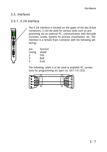
Hardware 3.5. Interfaces 3.5.1. V.24 interface The V.24 interface is located on the upper of the two D-Sub connectors. It can be used for various tasks such as programming via an external PC, communication with barcode scanners, scales, systems for process visualisation, etc. The interface is a female 9-pin connector with the following pin wiring: pin function casing shield 2 TxD 3 RxD 5 Gnd The following cable is to be used to establish PC connections for programming etc (part no. 657.151.03): 1 2 3 4 5 6 7 8 9 5 4 3 2 1 9 8 7 6 3 - 7
- Page 1 and 2: Kuhnke Electronics Instruction Manu
- Page 3 and 4: Table of contents Table of contents
- Page 5 and 6: Table of contents 4.5.2. External o
- Page 7 and 8: Table of contents B. PROFIBUS hardw
- Page 9 and 10: 1. Purpose of PC Control 645-12M In
- Page 11 and 12: Introduction Advantages of decentra
- Page 13 and 14: Introduction VEBES VEBES, the netwo
- Page 15 and 16: 2. Reliability and safety Reliabili
- Page 17 and 18: Reliability / safety 2.4. Safety Ou
- Page 19 and 20: Reliability / safety 2.5. Electroma
- Page 21 and 22: 2.5.5. Protection against external
- Page 23 and 24: 3. Hardware Hardware 3.1. Design 17
- Page 25 and 26: Hardware 3.2.2.1. Uninterrupted swi
- Page 27: Hardware 3.4.2. Setting the reset t
- Page 31 and 32: Hardware 3.6. Memory PC Control 645
- Page 33 and 34: Hardware 3.8.2. How to avoid addres
- Page 35 and 36: Hardware -- Activate the "Memory" o
- Page 37 and 38: Hardware To reserve a memory range
- Page 39 and 40: i n 0 2 4LV o g 0 2 4LV o Sa t da t
- Page 41 and 42: PC Control 645-12M used as PLC 4.1.
- Page 43 and 44: PC Control 645-12M used as PLC -- S
- Page 45 and 46: PC Control 645-12M used as PLC The
- Page 47 and 48: 4.2. Going online with KUBES PC Con
- Page 49 and 50: PC Control 645-12M used as PLC 4.2.
- Page 51 and 52: 4.3. Memory settings PC Control 645
- Page 53 and 54: 4.4. PLC working method PC Control
- Page 55 and 56: 4.5.1.1. Short description of local
- Page 57 and 58: 4.5.2. External operands as process
- Page 59 and 60: PC Control 645-12M used as PLC 4.5.
- Page 61 and 62: 4.5.3.1. Status of PROFIBUS master
- Page 63 and 64: 4.5.3.2. PEaxx.yy: DP slave status
- Page 65 and 66: 4.6. Summary of commands PC Control
- Page 67 and 68: PC Control 645-12M used as PLC 4.6.
- Page 69 and 70: PC Control 645-12M used as PLC 4.6.
- Page 71 and 72: PC Control 645-12M used as PLC 4.6.
- Page 73 and 74: 4.6.4. Shift and rotation commands
- Page 75 and 76: PC Control 645-12M used as PLC 4.6.
- Page 77 and 78: PC Control 645-12M used as PLC 4.6.
Hardware<br />
3.5. Interfaces<br />
3.5.1. V.24 interface<br />
The V.24 interface is located on the upper of the two D-Sub<br />
connectors. It can be used for various tasks such as programming<br />
via an external <strong>PC</strong>, communication with barcode<br />
scanners, scales, systems for process visualisation, etc. The<br />
interface is a female 9-pin connector with the following pin<br />
wiring:<br />
pin function<br />
casing shield<br />
2 TxD<br />
3 RxD<br />
5 Gnd<br />
The following cable is to be used to establish <strong>PC</strong> connections<br />
for programming etc (part no. 657.151.03):<br />
1 2 3 4 5<br />
6 7 8 9<br />
5 4 3 2 1<br />
9 8 7 6<br />
3 - 7


