PC Control / Profi Control 645-12M Instruction Manual pdf - Kuhnke
PC Control / Profi Control 645-12M Instruction Manual pdf - Kuhnke
PC Control / Profi Control 645-12M Instruction Manual pdf - Kuhnke

You also want an ePaper? Increase the reach of your titles
YUMPU automatically turns print PDFs into web optimized ePapers that Google loves.
PROFIBUS hardware installation<br />
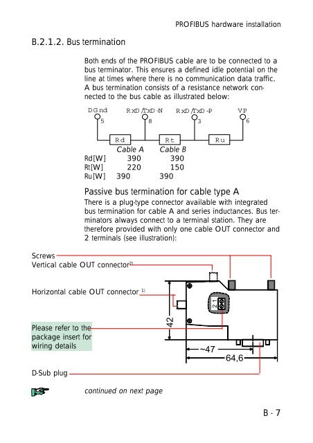
B.2.1.2. Bus termination<br />
Both ends of the PROFIBUS cable are to be connected to a<br />
bus terminator. This ensures a defined idle potential on the<br />
line at times where there is no communication data traffic.<br />
A bus termination consists of a resistance network connected<br />
to the bus cable as illustrated below:<br />
DGnd RxD/TxD-N RxD/TxD-P VP<br />
5<br />
8 3 6<br />
Rd<br />
Rt<br />
Cable A Cable B<br />
Rd [W] 390 390<br />
Rt [W] 220 150<br />
Ru [W] 390 390<br />
Screws<br />
Vertical cable OUT connector 2)<br />
Passive bus termination for cable type A<br />
There is a plug-type connector available with integrated<br />
bus termination for cable A and series inductances. Bus terminators<br />
always connect to a terminal station. They are<br />
therefore provided with only one cable OUT connector and<br />
2 terminals (see illustration):<br />
Ru<br />
Horizontal cable OUT connector 1)<br />
21<br />
Please refer to the<br />
package insert for<br />
wiring details<br />
42<br />
~47<br />
64,6<br />
D-Sub plug<br />
continued on next page<br />
B - 7