PC Control / Profi Control 645-12M Instruction Manual pdf - Kuhnke
PC Control / Profi Control 645-12M Instruction Manual pdf - Kuhnke
PC Control / Profi Control 645-12M Instruction Manual pdf - Kuhnke

Create successful ePaper yourself
Turn your PDF publications into a flip-book with our unique Google optimized e-Paper software.
PROFIBUS hardware installation<br />
B.2. Connection of bus stations<br />
When connecting the bus cable to the bus stations, make<br />
sure not to twist the data lines.<br />
Use pins 3 and 8 for communication connections to partner<br />
stations:<br />
Tip: Make a basic all-time decision as to which colour<br />
core is to be used for the data lines.<br />
We recommend:<br />
Pin Function Colour<br />
3 RXD/TXD-P red or white (lighter colour)<br />
8 RXD/TXD-N green or brown (darker colour)<br />
Both terminating stations are to be connected to a bus terminator<br />
(see chapter "B.2.1.2. Bus termination").<br />
B.2.1. Bus cable connectors<br />
There are various types of bus cables connectors available.<br />
The basic distinction is to be made between bus nodes – interfacing<br />
between two bus stations – and bus terminators –<br />
for terminating bus stations.<br />
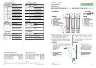
Terminal stat. <strong>Profi</strong> I/O 690E+ further stations<br />
6 7 8 9<br />
1 2 3 4 5<br />
Bus termination<br />
required!<br />
6 7 8 9<br />
1 2 3 4 5<br />
Bus node<br />
RxD/TxD-N<br />
RxD/TxD-P<br />
Shield<br />
Ill.: Bus network consisting of at least 3 stations<br />
B - 5