You also want an ePaper? Increase the reach of your titles
YUMPU automatically turns print PDFs into web optimized ePapers that Google loves.
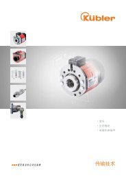
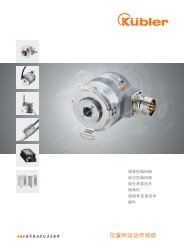
<strong>Absolute</strong> <strong>Encoders</strong> – <strong>Multiturn</strong><br />
Functional Safety, optical<br />
Sendix 5863 SIL / 5883 SIL (Shaft / Hollow shaft)<br />
SSI / BiSS-C + SinCos<br />
The absolute multiturn encoders Sendix 5863 SIL and 5883 SIL are<br />
perfectly suited for use in safety-related applications up to SIL3<br />
according to DIN EN ISO 61800-5-2 or PLe to DIN EN ISO 13849.<br />
The extra strong Safety-Lock Design interlocked bearings, the<br />
high integration density of the components based on OptoASIC<br />
technology and the rugged die-cast housing make these devices<br />
ideal also for demanding applications outdoors.<br />
RoHS<br />
Mechanical<br />
drive<br />
Safety-Lock TM<br />
High rotational<br />
speed<br />
Temperature<br />
IP<br />
High protection<br />
level<br />
High shaft load<br />
capacity<br />
Shock / vibration<br />
resistant<br />
Magnetic field<br />
proof<br />
Reverse polarity<br />
protection<br />
SinCos<br />
Seawater-resistant<br />
version on request<br />
Certified Safety<br />
• Certified by the BGIA - Institute for Occupational Safety and Health<br />
• Suitable for SIL3 applications acc. to DIN EN ISO 61800-5-2<br />
• Suitable for PLe applications acc. to DIN EN ISO 13849<br />
• SSI or BiSS-C interface with incremental SinCos tracks<br />
Flexible<br />
• Shaft and hollow shaft versions<br />
• Cable and connector variants<br />
• Various mounting options available<br />
Order code<br />
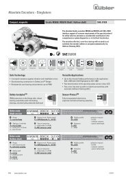
Shaft version<br />
8.5863SIL<br />
Type<br />
.<br />
1 X X X<br />
a<br />
b<br />
c<br />
d<br />
.<br />
X X 2 X<br />
e<br />
f<br />
g<br />
h<br />
If for each parameter of an encoder the underlined preferred option is selected,<br />
then the delivery time will be 10 working days for a maximum of 10 pieces.<br />
Qts. up to 50 pcs. of these types generally have a delivery time of 15 working days.<br />
a Flange<br />
1 = clamping flange, ø 58 mm, IP65<br />
b Shaft (ø x L)<br />
2 = 10 x 20 mm, with flat<br />
A = 10 x 20 mm, with feather key<br />
c Interface / Power supply<br />
3 = SSI or BiSS-C + 2048 ppr SinCos track /<br />
5 V DC<br />
4 = SSI or BiSS-C + 2048 ppr SinCos track /<br />
10 ... 30 V DC<br />
d Type of connection<br />
1 = axial cable (1 m PVC)<br />
2 = radial cable (1 m PVC)<br />
3 = M23 connector, 12-pin, axial<br />
4 = M23 connector, 12-pin, radial<br />
e Code<br />
B = SSI, Binary<br />
C = BiSS-C, Binary<br />
G = SSI, Gray<br />
f Resolution 1)<br />
A = 10 bit ST + 12 bit MT<br />
1 = 11 bit ST + 12 bit MT<br />
2 = 12 bit ST + 12 bit MT<br />
3 = 13 bit ST + 12 bit MT<br />
4 = 14 bit ST + 12 bit MT<br />
7 = 17 bit ST + 12 bit MT<br />
g Input / output 1)<br />
2 = SET, DIR inputs<br />
h Options (Service)<br />
1 = no Option<br />
2 = status LED<br />
3 = SET button and status LED<br />
optional on request<br />
- seawater-resistant<br />
- special cable length<br />
Order code<br />
Hollow shaft<br />
8.5883SIL<br />
Type<br />
.<br />
X X X X<br />
a<br />
b<br />
c<br />
d<br />
.<br />
X X 2 X<br />
e<br />
f<br />
g<br />
h<br />
If for each parameter of an encoder the underlined preferred option is selected,<br />
then the delivery time will be 10 working days for a maximum of 10 pieces.<br />
Qts. up to 50 pcs. of these types generally have a delivery time of 15 working days.<br />
a Flange<br />
A = with torque stop set, IP65<br />
B = with stator coupling, IP65<br />
b Hollow shaft<br />
3 = ø 10 mm<br />
4 = ø 12 mm<br />
5 = ø 14 mm<br />
K = ø 10 mm, tapered shaft<br />
c Interface / Power supply<br />
3 = SSI or BiSS-C + 2048 ppr SinCos track /<br />
5 V DC<br />
4 = SSI or BiSS-C + 2048 ppr SinCos track /<br />
10 ... 30 V DC<br />
d Type of connection<br />
2 = radial cable (1 m PVC)<br />
4 = M23 connector, 12-pin, radial<br />
E = tangential cable outlet<br />
cable length 1 m (PVC cable)<br />
e Code<br />
B = SSI, Binary<br />
C = BiSS-C, Binary<br />
G = SSI, Gray<br />
f Resolution 1)<br />
A = 10 bit ST + 12 bit MT<br />
1 = 11 bit ST + 12 bit MT<br />
2 = 12 bit ST + 12 bit MT<br />
3 = 13 bit ST + 12 bit MT<br />
4 = 14 bit ST + 12 bit MT<br />
7 = 17 bit ST + 12 bit MT<br />
g Input / output 1)<br />
2 = SET, DIR inputs<br />
h Options (Service)<br />
1 = no Option<br />
2 = status LED<br />
3 = SET button and status LED<br />
optional on request<br />
- seawater-resistant<br />
- special cable length<br />
1) Resolution, preset value and count direction are factory-programmable<br />
© Fritz Kübler GmbH, subject to errors and changes. 10/2012<br />
www.kuebler.com<br />
59
<strong>Absolute</strong> <strong>Encoders</strong> – <strong>Multiturn</strong><br />
Functional Safety, optical<br />
Sendix 5863 SIL / 5883 SIL (Shaft / Hollow shaft)<br />
SSI / BiSS-C + SinCos<br />
Connection technology<br />
Connector, self-assembly (straight)<br />
Cordset, pre-assembled with 2 m PVC cable<br />
M23 8.0000.5012.0000<br />
M23 8.0000.6901.0002.0031<br />
Further accessories can be found in the accessories section or in the accessories area of our website at: www.kuebler.com/accessories.<br />
Additional connectors can be found in the connection technology section or in the connection technology area of our website at: www.kuebler.com/connection_technology.<br />
You will find an overview of our systems and components for Functional Safety under www.kuebler.com/safety<br />
Notes regarding “Functional Safety”<br />
These encoders are suitable for use in safety-related systems up to SIL3 to<br />
DIN EN ISO 61800-5-2 and PLe to DIN EN ISO 13849 in conjunction with<br />
controllers or evaluation units, which possess the necessary functionality.<br />
Additional functions can be found in the operating manual.<br />
Mechanical characteristics<br />
Max. speed, shaft version<br />
without shaft seal (IP65) up to 70°C 12 000 min -1 , 10 000 min -1 (continuous)<br />
without shaft seal (IP65) up to Tmax 8 000 min -1 , 5 000 min -1 (continuous)<br />
with shaft seal (IP67) up to 70°C 11 000 min -1 , 9 000 min -1 (continuous)<br />
with shaft seal (IP67) up to Tmax 8 000 min -1 , 5 000 min -1 (continuous)<br />
Max. speed, hollow shaft version<br />
without shaft seal (IP65) up to 70°C 9 000 min -1 , 6 000 min -1 (continuous)<br />
without shaft seal (IP65) up to Tmax 6 000 min -1 , 3 000 min -1 (continuous)<br />
with shaft seal (IP67) up to 70°C 8 000 min -1 , 4 000 min -1 (continuous)<br />
with shaft seal (IP67) up to Tmax 4 000 min -1 , 2 000 min -1 (continuous)<br />
Starting torque, shaft version<br />
without shaft seal (IP65)<br />
< 0.01 Nm<br />
with shaft seal (IP67)<br />
< 0.05 Nm<br />
Starting torque, hollow shaft version<br />
without shaft seal (IP65)<br />
< 0.03 Nm<br />
Moment of inertia<br />
Shaft version 4.0 x 10 -6 kgm 2<br />
Hollow shaft version 7.0 x 10 -6 kgm 2<br />
Load capacity of shaft radial / axial 80 N / 40 N<br />
Weight<br />
approx. 0.45 kg<br />
Protection housing side IP67<br />
acc. to EN 60529 shaft side IP65, opt. IP67<br />
Working temperature range -40°C ... +90°C 1)<br />
Materials shaft/hollow shaft stainless steel<br />
flange aluminium<br />
housing zinc die-cast housing<br />
cable PVC<br />
Shock resistance acc. EN 60068-2-27 500 m/s 2 , 11 ms<br />
Vibration resistance acc. EN 60068-2-6 200 m/s 2 , 10 ... 150 Hz<br />
Electrical characteristics<br />
Supply voltage<br />
5 V DC ± 5% or 10 ... 30 V DC<br />
Current consumption 5 V DC max. 80 mA<br />
(w/o output load) 10 ... 30 V DC max. 50 mA<br />
Reverse polarity protection<br />
yes<br />
of the power supply (U B )<br />
UL approval File 224618<br />
Conforms to CE requirements acc. to EN 61000-6-2, EN 55011, EN 61800-5-2,<br />
EN 61508, EN 13849-1<br />
RoHS compliant acc. to<br />
EU-guideline 2002/95/EC<br />
General interface characteristics<br />
Output driver<br />
RS485 transceiver type<br />
Permissible load / channel<br />
max. 20 mA<br />
Signal level high typ 3.8 V<br />
low at I Load = 20 mA typ 1.3 V<br />
Short circuit proof outputs yes 2)<br />
SSI interface<br />
Singleturn resolution 10 ... 14 bits and 17 bit 3)<br />
Number of revolutions<br />
4096 (12 bit)<br />
Code<br />
Binary or Gray<br />
SSI clock rate ≤ 14 bit 50 kHz ... 2 MHz<br />
≥ 15 bit 50 kHz ... 125 kHz<br />
Monoflop time<br />
≤ 15 μs<br />
Note: If the clock starts cycling within the monoflop time, a second data transfer<br />
starts with the same data. If the clock starts cycling after the monoflop time, the<br />
data transfer starts with the new values. The update rate is dependent on the<br />
clock speed, data length and monoflop-time.<br />
Data refresh rate ≤ 14 bit < 1 μs<br />
15 ... 17 bit 4 μs<br />
Status and Parity bit<br />
optional on request<br />
BiSS-C interface<br />
Singleturn resolution 10 ... 14 bit and 17 bit 3)<br />
Number of revolutions<br />
4096 (12 bit)<br />
Code<br />
Binary<br />
Clock rate<br />
up to 10 MHz<br />
Max. update rate<br />
< 10 μs, depends on the clock rate<br />
and the data length<br />
Data refresh rate<br />
≤ 1 μs<br />
Note: – Bidirectional, factory programmable parameters are:<br />
resolution, code, direction, alarms and warnings<br />
– CRC data verification<br />
Output SinCos (A / B) 2048 ppr (optional incremental track)<br />
Max. frequency -3dB<br />
400 kHz<br />
Signal level 1 Vpp (± 10%)<br />
Short circuit proof<br />
yes<br />
DIR input<br />
A HIGH signal switches the direction of rotation from the default CW to CCW.<br />
This function can also be factory-programmed to be inverted. If DIR is changed<br />
when the device is already switched on, then this will be interpreted as an<br />
error. The LED will come ON and the status output will switch to LOW.<br />
1) Cable version: -30°C ... +90°C<br />
2) Short circuit to 0 V or to output, one channel at a time,<br />
supply voltage correctly applied<br />
3) Other options upon request<br />
60 www.kuebler.com © Fritz Kübler GmbH, subject to errors and changes. 10/2012
<strong>Absolute</strong> <strong>Encoders</strong> – <strong>Multiturn</strong><br />
Functional Safety, optical<br />
Sendix 5863 SIL / 5883 SIL (Shaft / Hollow shaft)<br />
SSI / BiSS-C + SinCos<br />
SET input or SET button<br />
Input<br />
active high<br />
Input type:<br />
comparator<br />
Signal level high min: 60 % of +V, max: +V<br />
low max: 25 % of +V (Supply voltage)<br />
Input current<br />
< 0.5 mA<br />
Min. pulse duration (SET)<br />
10 ms<br />
Timeout after SET signal<br />
14 ms<br />
Reaction time (DIR input)<br />
1 ms<br />
The encoder can be set to zero at any position by means of a HIGH signal on<br />
the SET input or by pressing the optional SET button (with a pencil, ball-point<br />
pen or similar). Other preset values can be factory-programmed.<br />
The SET input has a signal delay time of approx. 1 ms. Once the SET function<br />
has been triggered, the encoder requires an internal processing time of<br />
approx. 15 ms before the new position data can be read. During this time the<br />
LED is ON.<br />
Power-ON delay<br />
After Power-ON the encoder requires a time of approx. 150 ms before valid<br />
data can be read.<br />
LED<br />
The optional LED (red) serves to display various alarm or error messages.<br />
In normal operation the LED is OFF.<br />
If the LED is ON this indicates:<br />
- Sensor error, singleturn or multiturn (soiling, glass breakage etc.)<br />
- LED error, failure or ageing<br />
- Over- or under-temperature<br />
In the SSI mode, the fault indication can only be reset by switching off the<br />
power-supply to the device.<br />
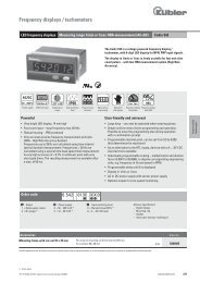
Terminal assignment<br />
Interface Type of connection Features Cable<br />
Signal: 0 V +V +C -C +D -D SET DIR A B H<br />
3, 4 1, 2, E SET, DIR<br />
Cable colour: WH BN GN YE GY PK BU RD BK VT GY-PK RD-BU Shield<br />
Interface Type of connection Features M23 connector<br />
Signal: 0 V +V +C -C +D -D SET DIR A B H<br />
3, 4 3, 4 SET, DIR<br />
Pin: 1 2 3 4 5 6 7 8 9 10 11 12 PH<br />
+V: Encoder power supply +V DC<br />
0 V: Encoder power supply ground (0V)<br />
+C, -C: Clock signal<br />
+D, -D: Data signal<br />
SET: Set input. The current position is set to zero.<br />
DIR: Direction input: If this input is active, the output values are counted backwards (decrease)<br />
when the shaft is turning clockwise.<br />
PH: Plug connector housing (shield)<br />
A, : Incremental output channel A<br />
B, : Incremental output channel B<br />
Top view of mating side, male contact base<br />
M23 connector, 12-pin<br />
© Fritz Kübler GmbH, subject to errors and changes. 10/2012<br />
www.kuebler.com<br />
61
<strong>Absolute</strong> <strong>Encoders</strong> – <strong>Multiturn</strong><br />
Functional Safety, optical<br />
Sendix 5863 SIL / 5883 SIL (Shaft / Hollow shaft)<br />
SSI / BiSS-C + SinCos<br />
Dimensions shaft version<br />
Clamping flange<br />
Flange type 1 with shaft type 2<br />
(Drawing with cable)<br />
10 [0.39]<br />
ca.83,5 [3.29]<br />
49,5 [1.95]<br />
3 [0.12]<br />
3 [0.12]<br />
3x120°<br />
20°<br />
2<br />
1<br />
58 [2.28]<br />
53 [2.09]<br />
36 [1.42]<br />
10 f7 [0.39]<br />
20 [0.79]<br />
max. 86 [3.39]<br />
13,25 [0.52]<br />
Flange type 1 with shaft type A<br />
(Drawing with M23 connector)<br />
1 3 x M3, 6 [0.24] deep<br />
2 3 x M4, 8 [0.32] deep<br />
58 [2.28]<br />
53 [2.09]<br />
36 f8 [1.42]<br />
[0.39]<br />
20 [0.79]<br />
88 [3.46]<br />
49,5 [1.95]<br />
6 [0,24]<br />
3 [0.12]<br />
3x120°<br />
20°<br />
87,5<br />
h7<br />
10<br />
10 [0.39]<br />
[3.44]<br />
2<br />
1<br />
3<br />
13,25 [0.52]<br />
62<br />
www.kuebler.com © Fritz Kübler GmbH, subject to errors and changes. 10/2012
<strong>Absolute</strong> <strong>Encoders</strong> – <strong>Multiturn</strong><br />
Functional Safety, optical<br />
Dimensions hollow shaft version<br />
Sendix 5863 SIL / 5883 SIL (Shaft / Hollow shaft)<br />
SSI / BiSS-C + SinCos<br />
With torque stop set<br />
Flange type A<br />
(Drawing with cable)<br />
67,5 [2.66]<br />
56,5 [2.22]<br />
0,31<br />
8<br />
150 [5.91]<br />
143,5 [5.56]<br />
67,5 [2.66]<br />
56,5 [2.22]<br />
0,98<br />
25<br />
127,5 [5,02]<br />
110 [4.62]<br />
75 [2.65]<br />
0,98<br />
25<br />
0,31<br />
8<br />
3x120°<br />
0,98<br />
25<br />
150 [5.91]<br />
143,5 [5.56]<br />
127,5 [5,02]<br />
110 [4.62]<br />
75 [2.65]<br />
0,98<br />
25<br />
58 [2.28]<br />
50 [1.97]<br />
max. 31 [1.22]<br />
max.86 [3.39]<br />
25 [0.98]<br />
0,39<br />
10<br />
58 [2.28]<br />
6 [0,24] 50 [1.97]<br />
max. 31 [1.22]<br />
0,98<br />
25<br />
0,98<br />
25<br />
max.86 [3.39]<br />
92,5 [3.52]<br />
25 [0.98]<br />
0,39<br />
10<br />
0,98<br />
25<br />
57,5 [1.86]<br />
[0,24]<br />
6<br />
0,98<br />
25<br />
H7<br />
D<br />
42 [1.65]<br />
0,98<br />
25<br />
92,5 [3.52]<br />
0,98<br />
25<br />
57,5 [1<br />
13,25 [0.52]<br />
13,25 [0.52]<br />
Torque pin with rectangular sleeve<br />
with M4 thread, 10 deep<br />
0,24<br />
6,2<br />
34 [1.41]<br />
22,8 [0.9]<br />
20 [0.79]<br />
[0,24]<br />
6<br />
[0.28]<br />
M4<br />
0,24<br />
6,2<br />
34 [1.41]<br />
22,8 [0.9]<br />
20 [0.79]<br />
[0,24]<br />
6<br />
67,5 [2.66]<br />
59,5 [2.34]<br />
56,5 [2.22]<br />
68 [2.68]<br />
63 [2.48]<br />
58<br />
53<br />
[2.28]<br />
[2.09]<br />
50 [1.97]<br />
max. 31 [1.22]<br />
[0.28]<br />
87,5 [3.44]<br />
22 [0.87]<br />
7<br />
M4<br />
7<br />
10 [0.39]<br />
SW 8<br />
10 [0.39]<br />
SW 8<br />
Flange with stator coupling and hollow shaft<br />
Flange type B<br />
(Drawing with M23 connector)<br />
25°<br />
1<br />
1 for (4x) M3 screw<br />
13,25 [0.52]<br />
Flange with stator coupling and tapered shaft<br />
Flange type B<br />
(Drawing with tangential cable outlet)<br />
78,5 [2.66]<br />
70,5 [2.34]<br />
67,5 [2,66]<br />
59,5 [2.22]<br />
68 [2.68]<br />
63 [2.48]<br />
58 [2.28]<br />
53 [2.09]<br />
50 [1.97]<br />
0,35<br />
8,8<br />
M 5<br />
10:1<br />
0,35<br />
8,9<br />
22 [0.87]<br />
25°<br />
3<br />
2<br />
0,85<br />
21,7<br />
31,5 [1.24]<br />
1<br />
1 for (4x) M3 screw<br />
2 Status LED<br />
3 SET button<br />
© Fritz Kübler GmbH, subject to errors and changes. 10/2012<br />
www.kuebler.com<br />
63

![more [PDF]](https://img.yumpu.com/23985247/1/190x247/more-pdf.jpg?quality=85)