KTA 3211. (2012-11) Pressure and Activity Retaining Components ...
KTA 3211. (2012-11) Pressure and Activity Retaining Components ...
KTA 3211. (2012-11) Pressure and Activity Retaining Components ...

Create successful ePaper yourself
Turn your PDF publications into a flip-book with our unique Google optimized e-Paper software.
Safety St<strong>and</strong>ards<br />
of the<br />
Nuclear Safety St<strong>and</strong>ards Commission (<strong>KTA</strong>)<br />
<strong>KTA</strong> <strong>32<strong>11</strong>.</strong>4 (<strong>2012</strong>-<strong>11</strong>)<br />
<strong>Pressure</strong> <strong>and</strong> <strong>Activity</strong> <strong>Retaining</strong> <strong>Components</strong> of Systems<br />
Outside the Primary Circuit;<br />
Part 4: Inservice Inspections <strong>and</strong> Operational Monitoring<br />
(Druck- und aktivitätsführende Komponenten von Systemen<br />
außerhalb des Primärkreises;<br />
Teil 4: Wiederkehrende Prüfungen und Betriebsüberwachung)<br />
Previous version of this Safety St<strong>and</strong>ard<br />
was issued 1996-06<br />
If there is any doubt regarding the information contained in this translation, the German wording shall apply.<br />
Editor:<br />
<strong>KTA</strong>-Geschaeftsstelle c/o Bundesamt fuer Strahlenschutz (BfS)<br />
Willy-Br<strong>and</strong>t-Strasse 5 • 38226 Salzgitter • Germany<br />
Telephone +49-30-18-333-1621 • Telefax +49-30-18-333-1625
<strong>2012</strong>-<strong>11</strong><br />
<strong>KTA</strong> SAFETY STANDARD<br />
<strong>Pressure</strong> <strong>and</strong> <strong>Activity</strong> <strong>Retaining</strong> <strong>Components</strong><br />
of Systems Outside the Primary Circuit;<br />
Part 4: Inservice Inspections <strong>and</strong> Operational Monitoring<br />
<strong>KTA</strong> <strong>32<strong>11</strong>.</strong>4<br />
CONTENTS<br />
Fundamentals .............................................................. 5<br />
1 Scope.................................................................. 5<br />
2 Definitions ........................................................... 6<br />
3 Safeguarding of required component quality........ 8<br />
4 Test procedures <strong>and</strong> techniques....................... 10<br />
4.1 General requirements ....................................... 10<br />
4.2 Examination of surfaces.................................... 10<br />
4.3 Examination for wall thickness reduction .......... 16<br />
4.4 Evaluation of the general condition................... 17<br />
4.5 <strong>Pressure</strong> test..................................................... 17<br />
4.6 Functional tests on safeguards against<br />
excessive pressure ........................................... 17<br />
5 Extent of testing <strong>and</strong> test intervals .................... 17<br />
5.1 General requirements ....................................... 17<br />
5.2 Extent of testing ................................................ 17<br />
5.3 Test intervals..................................................... 18<br />
6 Test <strong>and</strong> inspection manual .............................. 22<br />
6.1 Preparation ....................................................... 22<br />
6.2 Review <strong>and</strong> updating ........................................ 22<br />
7 Preparation <strong>and</strong> performance of tests............... 22<br />
7.1 General ............................................................. 22<br />
7.2 Preparation ....................................................... 22<br />
7.3 Performance ..................................................... 22<br />
7.4 Requirements regarding test personnel ............ 22<br />
8 Evaluation of test results................................... 22<br />
8.1 General ............................................................. 22<br />
8.2 Examinations of surfaces ..................................23<br />
8.3 Examination for wall thickness reduction...........25<br />
8.4 Evaluation of the general condition ...................25<br />
8.5 <strong>Pressure</strong> test .....................................................25<br />
8.6 Functional tests of safeguards against<br />
excessive pressure ............................................25<br />
9 Operational monitoring ......................................25<br />
9.1 General requirements........................................25<br />
9.2 Instrumentation..................................................25<br />
9.3 Monitoring of water <strong>and</strong> steam chemistry..........26<br />
9.4 Monitoring for leakage, vibrations, displacement<br />
of components <strong>and</strong> unrestrained<br />
movement of piping...........................................26<br />
9.5 Monitoring of accumulation of radiolysis gas.....26<br />
10 Participation in in-service inspections <strong>and</strong><br />
operational monitoring.......................................26<br />
<strong>11</strong> Documentation ..................................................26<br />
<strong>11</strong>.1 General .............................................................26<br />
<strong>11</strong>.2 Documents required for in-service<br />
inspections ........................................................26<br />
<strong>11</strong>.3 Period of document filing for in-service<br />
inspections ........................................................27<br />
<strong>11</strong>.4 Documents required for the monitoring of<br />
mechanical <strong>and</strong> thermal loadings ......................27<br />
Annex A: Regulations referred to in this Safety<br />
St<strong>and</strong>ard....................................................28<br />
Annex B: Changes with respect to the edition<br />
1996-06 <strong>and</strong> explanations (informative) ....30<br />
PLEASE NOTE: Only the original German version of this safety st<strong>and</strong>ard represents the joint resolution of the<br />
50-member Nuclear Safety St<strong>and</strong>ards Commission (Kerntechnischer Ausschuss, <strong>KTA</strong>). The German version was<br />
made public in the Bundesanzeiger (BAnz) of January, 23th, 2013. Copies may be ordered through the Wolters Kluwer<br />
Deutschl<strong>and</strong> GmbH, Postfach 2352, 56513 Neuwied, Germany (Telefax +49 (0) 2631 801-2223, E-Mail:<br />
info@wolterskluwer.de).<br />
All questions regarding this English translation should please be directed to:<br />
<strong>KTA</strong>-Geschaeftsstelle c/o BfS, Willy-Br<strong>and</strong>t-Strasse 5, 38226 Salzgitter, Germany
<strong>KTA</strong> <strong>32<strong>11</strong>.</strong>4 Page 4<br />
Comments by the editor:<br />
Taking into account the meaning <strong>and</strong> usage of auxiliary verbs in the German language, in this translation the following<br />
agreements are effective:<br />
shall<br />
shall basically<br />
shall normally<br />
should<br />
may<br />
indicates a m<strong>and</strong>atory requirement,<br />
is used in the case of m<strong>and</strong>atory requirements to which specific exceptions (<strong>and</strong> only<br />
those!) are permitted. It is a requirement of the <strong>KTA</strong> that these exceptions - other than<br />
those in the case of shall normally - are specified in the text of the safety st<strong>and</strong>ard,<br />
indicates a requirement to which exceptions are allowed. However, the exceptions used,<br />
shall be substantiated during the licensing procedure,<br />
indicates a recommendation or an example of good practice,<br />
indicates an acceptable or permissible method within the scope of this safety st<strong>and</strong>ard.
<strong>KTA</strong> <strong>32<strong>11</strong>.</strong>4 Page 5<br />
Fundamentals<br />
(1) The safety st<strong>and</strong>ards of the Nuclear Safety St<strong>and</strong>ards<br />
Commission (<strong>KTA</strong>) have the task of specifying those safety<br />
related requirements which shall be met with regard to precautions<br />
to be taken in accordance with the state of science <strong>and</strong><br />
technology against damage arising from the construction <strong>and</strong><br />
operation of the facility (Sec. 7 para 2 subpara 3 Atomic Energy<br />
Act -AtG -) in order to attain the protection goals specified<br />
in the Atomic Energy Act <strong>and</strong> the Radiological Protection Ordinance<br />
(StrlSchV) <strong>and</strong> which are further detailed in the ”Safety<br />
Criteria for Nuclear Power Plants” <strong>and</strong> in the ”Incident<br />
Guidelines”.<br />
(2) Criterion 1.1, “Principles of Safety Precautions” of the<br />
Safety Criteria requires, among other things, a comprehensive<br />
quality assurance for fabrication <strong>and</strong> erection. In addition, the<br />
Criterion 2.1, “Quality Assurance” requires the preparation <strong>and</strong><br />
application of design rules, construction rules, testing <strong>and</strong> inspection<br />
rules as well as the documentation of quality assurance.<br />
The criteria 4.2 "Residual Heat Removal during Specified<br />
Normal Operation", 4.3 "Residual Heat Removal after Loss-of-<br />
Coolant", 5.3 "Equipment for Control <strong>and</strong> Shutdown of the<br />
Nuclear Reactor", <strong>and</strong> 8.5 "Heat Removal from the Containment"<br />
specify further requirements regarding the design <strong>and</strong><br />
quality of the safety systems.<br />
The Safety St<strong>and</strong>ard <strong>KTA</strong> <strong>32<strong>11</strong>.</strong>4 is intended to specificy detailed<br />
measures which shall be taken to meet these requirements<br />
within the scope of its application. For this purpose, a<br />
large number of st<strong>and</strong>ards from conventional engineering, in<br />
particular DIN st<strong>and</strong>ards, are also used.<br />
For the pressure <strong>and</strong> activity retaining components of systems<br />
outside the primary circuit the requirements of the aforementioned<br />
safety criteria are further concretised with the following<br />
Safety St<strong>and</strong>ards<br />
<strong>KTA</strong> <strong>32<strong>11</strong>.</strong>1 Materials <strong>and</strong> Product Forms,<br />
<strong>KTA</strong> <strong>32<strong>11</strong>.</strong>2 Design <strong>and</strong> Analysis,<br />
<strong>KTA</strong> <strong>32<strong>11</strong>.</strong>3 Manufacture.<br />
(3) The scope specified in this Safety St<strong>and</strong>ard includes<br />
those pressure <strong>and</strong> activity retaining systems <strong>and</strong> components<br />
outside of the reactor coolant pressure boundary which are of<br />
special safety related significance (in accordance with Annex<br />
1 of the RSK Guidelines for Pressurized Water Reactors<br />
<strong>and</strong> the corresponding components of Boiling Water Reactors).<br />
(4) The task of this Safety St<strong>and</strong>ard with respect to operational<br />
monitoring is to determine measures regarding the monitoring<br />
of causes <strong>and</strong> consequences of damage mechanisms.<br />
a) Monitoring of causes:<br />
aa) monitoring of the parameters <strong>and</strong> data relevant to<br />
component integrity,<br />
ab) monitoring of the quality of water <strong>and</strong> steam.<br />
b) Monitoring of consequences by:<br />
ba) in-service inspections,<br />
bb) leakage monitoring,<br />
c) Documentation <strong>and</strong> continuous recording of the monitoring<br />
results along with a foresighted evaluation in order to limit<br />
operational damage mechanisms.<br />
(5) The task of this Safety St<strong>and</strong>ard with respect to inservice<br />
inspections is to determine the relevant measures as<br />
listed in a) to d) hereinafter in order to ascertain <strong>and</strong> evaluate<br />
the actual component condition at the date of testing by:<br />
a) non-destructive examinations of the external <strong>and</strong> internal<br />
surfaces of pressure <strong>and</strong> activity retaining components,<br />
b) evaluation of the general condition during regular plant<br />
inspection,<br />
c) pressure tests as integral loading test,<br />
d) functional tests addressing the safeguards against excessive<br />
pressure.<br />
All above tests <strong>and</strong> examinations shall be documented in a socalled<br />
“test <strong>and</strong> inspection manual” which takes into consideration<br />
the requirements for the individual component <strong>and</strong><br />
contains the entire extent of in-service inspections.<br />
(6) During in-service inspections, test <strong>and</strong> examination procedures<br />
are used to detect defects due to operation in due<br />
time prior to reaching the acceptance level. When determining<br />
the extent of tests <strong>and</strong> examinations as well as the items to be<br />
examined, the design, material properties, fabrication processes<br />
<strong>and</strong> loading of the respective component as well as<br />
experience gained with already performed inspections shall be<br />
taken into consideration.<br />
(7) The quality of the component with regard to materials,<br />
design <strong>and</strong> manufacture shall be documented <strong>and</strong> be evaluated<br />
by continuously recording the accumulated operational<br />
loadings including commissioning, <strong>and</strong> the results of the inservice<br />
inspections.<br />
1 Scope<br />
(1) This Safety St<strong>and</strong>ard shall apply to in-service inspections<br />
of the pressure retaining walls of pressure <strong>and</strong> activity retaining<br />
systems <strong>and</strong> components of light water reactors which are<br />
not part of its reactor coolant pressure boundary but do have a<br />
certain significance with respect to reactor safety. This is given<br />
in the case where one of the following criteria applies:<br />
a) The plant facility is required for the mitigation of design<br />
basis accidents with regard to shutdown, long-term maintenance<br />
of subcriticality <strong>and</strong> with regard to direct residual<br />
heat removal.<br />
Requirements regarding components of systems which<br />
only indirectly serve in residual heat removal – these are<br />
the non-radioactivity retaining closed cooling water systems<br />
<strong>and</strong> service water systems – shall be specified on a<br />
plant-specific basis taking the design redundancy (e.g. redundancy,<br />
diversity) into consideration.<br />
b) Large energies are released in case of failure of the plant<br />
facilities <strong>and</strong> no mitigating measures such as structural<br />
measures, spatial separation or other safety measures are<br />
available to keep the effects of failure to an acceptable limit<br />
with respect to nuclear safety.<br />
c) A failure of the plant facilities could either directly, or indirectly<br />
through a chain of assumed sequential events, lead<br />
to a design basis accident in accordance with Sec. 49<br />
para. 1 of the Radiation Protection Ordinance (StrlSchV).<br />
d) Systems <strong>and</strong> components to which none of the criteria a)<br />
through c) apply, the failure of which, however, would lead<br />
to major plant internal damages – these are the components<br />
of Group II from Appendix to Sec. 4.2 of the RSK<br />
Guidelines for PWR <strong>and</strong> the corresponding components<br />
for BWR. With regard to the intensity of testing <strong>and</strong> documentation<br />
graduated levels may apply.<br />
(2) The scope of this Safety St<strong>and</strong>ard extends to the following<br />
components:<br />
a) pressure vessels,<br />
b) piping <strong>and</strong> piping products including small-bore pipes,<br />
c) pumps,<br />
d) valves,<br />
e) heat exchangers<br />
including the integral parts of the component support structures.<br />
Note:<br />
The secondary shell of the steam generators including the feedwater<br />
inlet <strong>and</strong> main steam exit nozzles up to the pipe connecting<br />
welds, but not the minor nozzles <strong>and</strong> nipples are covered<br />
by the scope of <strong>KTA</strong> 3201.4.
<strong>KTA</strong> <strong>32<strong>11</strong>.</strong>4 Page 6<br />
(3) This Safety St<strong>and</strong>ard does not apply to<br />
a) internals of components (that are not constituent part of<br />
the pressure retaining wall) <strong>and</strong> accessories,<br />
b) systems <strong>and</strong> plant facilities performing auxiliary functions<br />
for the systems dealt with in this Safety St<strong>and</strong>ard,<br />
c) those system parts where the system pressure is determined<br />
solely by the geodetic pressure level in the suction<br />
regime,<br />
d) component parts of the power transmission in pumps <strong>and</strong><br />
valves nor to the tests with respect to proof of functional<br />
capability,<br />
e) tests of functional capability within the framework of inservice<br />
inspections, except functional tests addressing the<br />
safeguards against excessive pressure,<br />
Note:<br />
Functional tests of shutdown systems are laid down in <strong>KTA</strong><br />
3103, functional tests of residual heat removal systems in <strong>KTA</strong><br />
3301 <strong>and</strong> functional tests of heat removal systems for fuel assembly<br />
storage pools in <strong>KTA</strong> 3303.<br />
(4) This Safety St<strong>and</strong>ard shall apply to systems <strong>and</strong> components<br />
which have been designed <strong>and</strong> manufactured in accordance<br />
with <strong>KTA</strong> <strong>32<strong>11</strong>.</strong>1, <strong>KTA</strong> <strong>32<strong>11</strong>.</strong>2 <strong>and</strong> <strong>KTA</strong> <strong>32<strong>11</strong>.</strong>3.<br />
(5) This Safety St<strong>and</strong>ard may also be applied to those components<br />
or component parts where an evaluation performed in<br />
due consideration of the state of science <strong>and</strong> technology<br />
showed that the principles of basic safatey are complied with<br />
<strong>and</strong> that no additional requirements for in-service inspections<br />
<strong>and</strong> operational monitoring are required.<br />
(6) In the case of components that do not meet the requirements<br />
under paragraph (4) or (5), increased requirements<br />
regarding inservice inspections <strong>and</strong> operational monitoring<br />
may have to be specified on the basis of the special situations.<br />
Note:<br />
Besides the requirements possibly to be met regarding in-service<br />
inspection <strong>and</strong> operational monitoring further measures to be taken<br />
may be taken into account.<br />
(7) In the case of components <strong>and</strong> systems outside the<br />
reactor coolant pressure boundary for which restricted designbasis<br />
leak <strong>and</strong> break assumptions are made, the component<br />
integrity shall be ensured during the total operational lifetime<br />
by means of an consistent concept in accordance with <strong>KTA</strong><br />
3201.4, Section 3 (integrity concept).<br />
Note:<br />
The procedures for break preclusion are laid down in <strong>KTA</strong> 3206<br />
(in course of preparation).<br />
(8) This Safety St<strong>and</strong>ard also lays down the requirements<br />
for in-service inspections <strong>and</strong> operational monitoring of piping<br />
≤ DN 50.<br />
2 Definitions<br />
(1) Pipe attachment weld<br />
The pipe attachment weld is a weld seam that connects the<br />
nozzle of a component with the corresponding pipe section.<br />
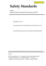
(2) Indications <strong>and</strong> types of flaws<br />
The correlation between indications <strong>and</strong> flaws are shown in<br />
Figure 2-1.<br />
detectable indications<br />
recordable indications<br />
relevant indication<br />
minimum detection level of<br />
examination procedure<br />
noise level<br />
Indications<br />
evaluation limit for I.I.<br />
recording level for F.E. <strong>and</strong> I.I<br />
F.E: evaluation during fabrication<br />
Flaws<br />
critical flaw size<br />
I.I.: in-service inspection<br />
acceptance level with proof<br />
critical flaws<br />
acceptance level without proof<br />
Figure 2-1: Indications <strong>and</strong> types of flaws<br />
(3) Relevant indication<br />
Relevant indication is an indication reaching or exeeding the<br />
evaluation limit.<br />
(4) Operational flaws<br />
Operational flaws are flaws due to operational damage mechanisms.<br />
(5) Higher stress locations<br />
Higher stress locations are such locations of a component or<br />
component part that<br />
a) compared to the general level of stress intensity are more<br />
highly stressed taking the frequency additionally into account<br />
or<br />
b) are more susceptible to corrosive action.<br />
(6) Integrity<br />
Integrity is the condition of a component or barrier, at which<br />
the required safety criteria with regard to strength, resistance<br />
to fracture <strong>and</strong> leak tightness are met.<br />
(7) Reference st<strong>and</strong>ard<br />
Reference st<strong>and</strong>ards to adjust <strong>and</strong> examine the test system or<br />
to examine the detection medium are<br />
a) in the case of ultrasonic testing: unclad test blocks of a<br />
known material, with predetermined surface quality <strong>and</strong><br />
geometry, e.g. calibration block no. 1 to DIN EN 12223 or<br />
calibration block no. 2 to DIN EN ISO 7963,<br />
b) in the case of penetrant testing: reference block 2 to DIN<br />
EN ISO 3452-3,<br />
c) in the case of magnetic particle testing: flux indicator for<br />
controlling the detection medium (reference block 1 to DIN<br />
EN ISO 9934-2 Annex B),<br />
d) in the case of visual testing: test pattern to DIN 25435-4,<br />
e) in the case of radiographic testing: image quality indicator to<br />
DIN EN 462-1,<br />
f) in the case of eddy current testing: reference block adapted<br />
to the task, made of a known material <strong>and</strong> with a specific<br />
surface quality <strong>and</strong> geometry.<br />
(8) Measured values<br />
Measured values are documented <strong>and</strong> stored values (e.g.<br />
pressure, temperature, amplitude, time base ranges, position).<br />
unacceptable flaws<br />
acceptable flaws
<strong>KTA</strong> <strong>32<strong>11</strong>.</strong>4 Page 7<br />
(9) Detection threshold<br />
Detection threshold is the lowest limit of detection of indications.<br />
(10) Types of tests, test procedures <strong>and</strong> techniques<br />
The terms, their acronyms <strong>and</strong> correlation of the types of<br />
tests, test procedures <strong>and</strong> techniques are shown in Table 2-1.<br />
(<strong>11</strong>) Examination of surfaces<br />
A surface examination is a non-destructive examination using<br />
techniques which allow detecting indications on the surface<br />
<strong>and</strong> near-surface regions in which case the depth examined<br />
depends on the method.<br />
(12) Quality required<br />
The required quality means the condition of a part, component<br />
or system with respect to their capability of meeting the specified<br />
requirements.<br />
(13) Noise<br />
Depending on the test conditions, r<strong>and</strong>omly distributed additional<br />
signals due to noise of the test system, reflections from the<br />
structure of the material or its surface condition.<br />
(14) Noise level<br />
Noise level means the 95 % value of the cumulative frequency<br />
of the heights of the noise signals in the examined volume free<br />
from defects.<br />
(15) Recording level<br />
Recording level means the specified threshold at which, when<br />
being reached or exceeded, indications from the test object are<br />
recorded.<br />
(16) Representative locations, components or component<br />
parts<br />
Such locations, components or component parts are considered<br />
to be representative where the in-service inspection will<br />
lead to sufficiently comparable safety related results for other<br />
locations, components or component parts, taking into consideration<br />
the material composition, design <strong>and</strong> manufacturing<br />
quality as well as the stress type, level <strong>and</strong> frequency.<br />
(17) Authorized inspector<br />
The authorized inspector for the tests <strong>and</strong> inspections to be<br />
conducted in accordance with this Safety St<strong>and</strong>ard is the<br />
authorized inspector called in by the licensing or supervisory<br />
authority in accordance with Section 20 of the Atomic Energy<br />
Act.<br />
(18) Damage mechanisms<br />
Damage mechanisms are all physical, chemical <strong>and</strong> biological<br />
processes which may impair the integrity or function of a component.<br />
(19) St<strong>and</strong>ard instrumentation<br />
The st<strong>and</strong>ard instrumentation serves to monitor the parameters<br />
<strong>and</strong> data relevant to the integrity of components within the<br />
scope of this Safety St<strong>and</strong>ard <strong>and</strong> comprises measuring<br />
equipment to monitor global loadings <strong>and</strong> - if required - measuring<br />
equipment to monitor local loadings.<br />
(20) Nozzle attachment <strong>and</strong> insertion weld<br />
A nozzle attachment <strong>and</strong> insertion weld is a weld seam that<br />
connects the nozzle with the vessel wall or the pipe wall.<br />
(21) Welded joint<br />
A welded joint is a weld seam that joins component parts the<br />
cross-sections of which have been adapted in the connecting<br />
area.<br />
(22) Reference block<br />
A reference block is a block corresponding to the test object<br />
with respect to test-relevant characteristics (e.g. material, weld<br />
design, shape, wall thickness) <strong>and</strong> that contains reference<br />
flaws (e.g. grooves, bores) adapted to the individual testing<br />
task.<br />
(23) Acceptance level with proof<br />
The acceptance level with proof relates to a defect size that<br />
can be accepted when being proved (e.g. by fracture mechanics<br />
verification) to be less than rejectable.<br />
(24) Acceptance level without proof<br />
The acceptance level without proof relates to a defect condition<br />
that is left unchanged <strong>and</strong> can be accepted without further<br />
proof.<br />
Serial<br />
Number<br />
1 Examination of surfaces<br />
Type of Test Test Procedure Test Technique<br />
Magnetic particle testing (MT) e.g. field magnetization by magnetomotive force<br />
Liquid penetrant testing (PT) e.g. dye penetrant testing<br />
Ultrasonic testing<br />
Eddy-current testing<br />
Radiographic testing<br />
Visual testing<br />
Ultrasonic testing<br />
(UT)<br />
e.g. transceiver probe technique, dual search unit<br />
technique, mode conversion technique, phasedarray<br />
technique<br />
(ET) Single frequency, multiple frequency<br />
(RT) X-ray, Radioisotope<br />
(VT) Selective or integral visual examination with or<br />
without optical means<br />
(UT)<br />
E.g. wall thickness measurement with measuring<br />
techniques 1 to 3 acc. to DIN EN 14127<br />
2 Examination for wall thinning Radiographic testing (RT) Wall thickness measurement with projection<br />
technique, e.g. computerised radiography with<br />
imaging plates<br />
3 Evaluation of the general condition Regular plant inspection<br />
4 <strong>Pressure</strong> test Hydrostatic test<br />
5 Functional test<br />
Table 2-1:<br />
Type of tests, test procedures <strong>and</strong> techniques
<strong>KTA</strong> <strong>32<strong>11</strong>.</strong>4 Page 8<br />
3 Safeguarding of required component quality<br />
(1) The principles laid down in this Section serve to safeguard<br />
the required component or system quality with respect<br />
to the functional capability of plant components acc. to subclause<br />
1 (1) a) <strong>and</strong> with respect to the prevention of failure of<br />
plant facilities, systems or components involving serious consequences<br />
as indicated in sub-clauses 1 (1) b) to d) (see also<br />
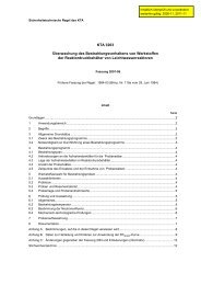
Figure 3-1).<br />
(2) Temporary disturbance of individual component integrity<br />
shall neither lead to<br />
a) a loss of functional capability of plant facilities as indicated<br />
in sub-clause 1 (1) a) nor<br />
b) to plant facilities failure involving serious consequences as<br />
indicated in sub-clauses 1 (1) b) to d).<br />
(3) The required quality as regards proper design <strong>and</strong> manufacture<br />
shall be the result of meeting the requirements of <strong>KTA</strong><br />
<strong>32<strong>11</strong>.</strong>1, <strong>KTA</strong> <strong>32<strong>11</strong>.</strong>2 und <strong>KTA</strong> <strong>32<strong>11</strong>.</strong>3 or the principles of basic<br />
safety.<br />
Note:<br />
See related sub-clauses 1 (4) <strong>and</strong> 1 (5).<br />
(4) Where components deviate from the requirements of the<br />
Safety St<strong>and</strong>ards <strong>KTA</strong> <strong>32<strong>11</strong>.</strong>1, <strong>KTA</strong> <strong>32<strong>11</strong>.</strong>2 <strong>and</strong> <strong>KTA</strong> <strong>32<strong>11</strong>.</strong>3 or<br />
from the principles of basic safatey such deviations shall be<br />
evaluated as to what extent increased requirements for inservice<br />
inspections <strong>and</strong> operational monitoring have to be laid<br />
down.<br />
(5) For components for which a changed state of knowledge<br />
regarding possible damage mechanisms is available, additional<br />
requirements shall be laid down, where required, with<br />
regard to in-service inspections <strong>and</strong> operational monitoring<br />
with due respect of the specific conditions prevailing.<br />
Note:<br />
Besides possible requirements for st<strong>and</strong>ard instrumentation <strong>and</strong><br />
in-service inspections further measures, e.g. preventive maintenance,<br />
may be taken into account.<br />
(6) To safeguard the required quality during operation<br />
a) operational monitoring measures,<br />
b) monitoring of the consequences of operational damage<br />
mechanisms,<br />
<strong>and</strong><br />
c) preventive maintenance measures<br />
shall be taken <strong>and</strong> be evaluated in accordance with Figure<br />
3-1 (8).<br />
(7) Where the required quality is no more available, respective<br />
measures shall be taken (Figure 3-1 (9)).<br />
(8) The effectiveness of the measures taken with respect to<br />
safeguarding against operational damage mechnisms shall be<br />
assessed (Figure 3-1 (10)).<br />
(9) Changes in the state of knowledge, e.g. due to new requirements<br />
for incident control, due to damage occurred, in the<br />
case of assessment of ageing phenomenons or in the case of<br />
other safety analyses, shall be considered within the reevaluation<br />
of required component quality during further operation<br />
(see Figure 3-1).<br />
(10) The procedural steps as per Figure 3-1 form an consistent<br />
concept to ensure the required component <strong>and</strong> system<br />
quality.
<strong>KTA</strong> <strong>32<strong>11</strong>.</strong>4 Page 9<br />
(1)<br />
Assessment of<br />
the actual<br />
construction<br />
Determination of<br />
relevant loadings<br />
incl. fluid (2)<br />
(1) Criteria<br />
- material<br />
- welding<br />
- design<br />
- existing relevant indications<br />
from design <strong>and</strong><br />
manufacturing documents<br />
Actual Quality<br />
(3)<br />
In<br />
accordance with<br />
<strong>KTA</strong> <strong>32<strong>11</strong>.</strong>1-.3 ?<br />
(5)<br />
yes<br />
no<br />
Supplementary<br />
measures<br />
(4)<br />
no<br />
yes<br />
Determination of possible operational demage mechanisms<br />
Evaluation of the quality obtained<br />
Have<br />
specified load cases<br />
been satisfied?<br />
(2) Data<br />
- specified operational <strong>and</strong><br />
incidence loadings<br />
- previous operational loadings<br />
(3) This check is only possible for<br />
components > DN 50.<br />
The criterion of this check is the quality<br />
obtained upon design <strong>and</strong> manufacture<br />
resulting if the requirements of <strong>KTA</strong> <strong>32<strong>11</strong>.</strong>1,<br />
<strong>KTA</strong> <strong>32<strong>11</strong>.</strong>2 <strong>and</strong> <strong>KTA</strong> <strong>32<strong>11</strong>.</strong>3 or the principles<br />
of basic safety are satisfied.<br />
This criterion is also satisfied if deviations<br />
do not require additional stipulations<br />
for in-service inspections or maintenance<br />
measures.<br />
For components ≤ DN 50 the same<br />
requirements apply accordingly in which<br />
case the concrete requirements as regards<br />
the actual condition are to be laid down<br />
for each individual plant.<br />
(6)<br />
Additional<br />
measures<br />
no<br />
Required<br />
quality obtained?<br />
yes<br />
(4) Additional measures (examples)<br />
- more detailed analysis<br />
- materials testing<br />
- special tests <strong>and</strong> examinations<br />
- adaptation of the st<strong>and</strong>ard instrumentation<br />
- adaptation of the in-service inspection concept<br />
Safeguarding of required quality<br />
during further operation<br />
(5) Evaluation criteria<br />
- stresses<br />
- fatigue analysis usage factor<br />
- safety margin to failure<br />
- corrosion<br />
Safeguarding during operation<br />
(7 a) Operational monitoring<br />
(7 b) Monitoring of consequences of possible<br />
operational damage mechanisms<br />
(7 c) Preventive maintenance<br />
(8)<br />
(9)<br />
(10)<br />
Evaluation of results<br />
Establishment of measures, if necessary<br />
Evaluation of active<br />
damage mechanisms<br />
Required<br />
quality obtained?<br />
yes<br />
Consistent<br />
concept<br />
no<br />
Change in<br />
state of<br />
knowledge,<br />
ageing<br />
management<br />
requirements<br />
Additional<br />
measures<br />
(6) Measures (examples)<br />
- modification of<br />
- process technology<br />
- hardware<br />
(7a) Operational monitoring<br />
- adherence to operational parameters<br />
specified (pressure, temperature,<br />
water chemistry)<br />
- monitoring of switching operations<br />
Measures<br />
- verifikation by st<strong>and</strong>ard instrumentation<br />
(7b) Monitoring of consequences of<br />
operational damage mechanisms, e.g.:<br />
- cracking<br />
- corrosion<br />
- reduction of wall thickness<br />
Measures (examples)<br />
- non-destructive examination<br />
- plant inspection by patrolling<br />
- leakage monitoring<br />
(7c) Preventive maintenance<br />
- Time or condition-oriented maintenance<br />
- functional tests<br />
- leakage tests<br />
(8) Evaluation criteria<br />
- stresses<br />
- fatigue analysis usage factor<br />
- safety margin to failure<br />
- corrosion<br />
(9) Measures (examples)<br />
- modification of<br />
- process technology<br />
- hardware<br />
- Adaptation of<br />
- st<strong>and</strong>ard instrumentation<br />
- preventive maintenance<br />
- in-service inspection concept<br />
- special tests <strong>and</strong> examinations<br />
(10) Criteria<br />
possible operational damage mechanisms<br />
safeguarded<br />
- cracking<br />
- corrosion<br />
- reduction of wall thickness<br />
Figure 3-1: Safeguarding of the required component quality
<strong>KTA</strong> <strong>32<strong>11</strong>.</strong>4 Page 10<br />
4 Test procedures <strong>and</strong> techniques<br />
4.1 General requirements<br />
4.1.1 Selection of test procedures <strong>and</strong> techniques<br />
(1) The test procedures <strong>and</strong> techniques shall be chosen<br />
such that service-induced flaws with their possible orientations<br />
will be detected. Such orientations are:<br />
a) planes perpendicular to the directions of principal stress,<br />
b) planes parallel to the fusion faces of weld seams (longitudinal<br />
flaws),<br />
c) planes perpendicular to the direction of welding progress<br />
(transverse flaws),<br />
d) planes parallel to the surface (wall thinning).<br />
(2) The test procedures as per Table 2-1 as well as per<br />
Sections 4.2 <strong>and</strong> 4.3 shall basically be applied. Other test<br />
procedures are permitted provided their suitability for achieving<br />
the test objective has been demonstrated.<br />
(3) The surfaces of components made of ferritic materials<br />
shall preferably be examined by magnetic particle testing. In<br />
the case of components made of austenitic materials the surfaces<br />
shall preferably be examined by liquid penetrant testing.<br />
(4) The test procedures <strong>and</strong> techniques for testing areas of<br />
austenitc steel base metals for stress corrosion cracking shall<br />
be selected such that defects oriented in both axial <strong>and</strong> circumferential<br />
direction can be detected.<br />
(5) In the case of ultrasonic testing, several techniques may<br />
be applied, where required, to fulfil the testing task.<br />
Note:<br />
See DIN 25435-1 Annex A for test techniques.<br />
(6) During ultrasonic testing scanning from both sides is<br />
basically required. Where, for design reasons, scanning from<br />
both sides is not possible, scanning from one side shall ensure<br />
sufficient sensitivity (e.g. by additional test techniques).<br />
(7) Mechanised ultrasonic examinations are required if<br />
a) an evaluation is not possible without extensive recordings<br />
<strong>and</strong> representation of measured data to DIN 25435-1 (e.g.<br />
in the case of spurious echoes on austenitic welds, of<br />
flaws due to external contour in the case of root notches,<br />
of complex geometries of nozzle welds),<br />
or<br />
b) by this means a reduction of radiation exposure of NDT<br />
personnel can be achieved.<br />
(8) Other test procedures shall normally be performed by<br />
mechanised examinations if the criteria to sub-clause (7) apply<br />
accordingly.<br />
(9) If the test results from one procedure alone deliver insufficient<br />
information, then an additional procedure shall be applied<br />
that is based on physical interaction different from the<br />
first. Where the results obtained from the additional test procedure<br />
are not sufficient, further steps shall be laid down by<br />
agreement with the authorized inspector.<br />
4.1.2 Suitability of test procedures<br />
(1) The suitability of test procedures <strong>and</strong> techniques the<br />
application of which for the respective testing task is not sufficiently<br />
described in st<strong>and</strong>ards shall be verified. The type <strong>and</strong><br />
extent of verification shall be laid down with respect to each<br />
component. In the case of materials or complex geometries<br />
that are difficult to examine, the suitability of the test procedures<br />
shall basically be demonstrated to the methodology of<br />
VGB Guideline R 516 (VGB-ENIQ-Guideline) on reference<br />
blocks. Where test procedures or techniques are to be applied<br />
for which a qualified test technique is available <strong>and</strong> the applicability<br />
of which has been ascertained by the authorized inspector,<br />
no further proof of suitability is required.<br />
(2) The test procedures <strong>and</strong> techniques are suited if their<br />
capability of detecting defects as required by Sections 4.2 <strong>and</strong><br />
4.3 in consideration of the type <strong>and</strong> location of the defects is<br />
satisfied.<br />
(3) Where the required detection capability is not achieved in<br />
limited areas by the test procedures selected, special proofs<br />
shall be furnished regarding the effectiveness of the test or an<br />
analytical proof (e.g. fracture mechanic analysis) shall be<br />
performed. Where required, the inspection intervals e.g. shall<br />
be reduced.<br />
4.1.3 Comparability of the results of consecutive tests<br />
(1) The results of consecutive tests must be comparable to<br />
each other. If the test procedure or technique is changed, a<br />
proof of the comparability of results shall be furnished. This<br />
may e.g. made by evaluating possible deviations or supplementary<br />
use of the preceding test procedures or techniques.<br />
(2) If in-service inspections are performed manually, the<br />
results of the first in-service inspection shall be compared with<br />
that production test which qualifies the final fabrication condition<br />
of the component.<br />
(3) If in-service inspections are to be performed in a mechanized<br />
way, a reference test is initially required using the same<br />
testing equipment as intended to be used later for the inservice<br />
inspections.<br />
4.1.4 Recording of test results<br />
(1) In the case of mechanically performed tests, all measured<br />
values <strong>and</strong> the corresponding coordinates shall be documented<br />
by automatic recording equipment.<br />
(2) In the case of manually performed tests all indications<br />
reaching or exceeding the recording level <strong>and</strong> the corresponding<br />
coordinates shall be recorded.<br />
(3) The radiographic images shall show the coordinates (e,g,<br />
item to be examined, zero point, direction of counting).<br />
4.2 Examination of surfaces<br />
4.2.1 Magnetic particle testing<br />
When performing magnetic particle testing, the requirements<br />
of DIN 25435-2 shall be met.<br />
4.2.2 Liquid penetrant testing<br />
When performing liquid penetrant testing, the requirements of<br />
DIN 25435-2 shall be met.<br />
4.2.3 Ultrasonic examination procedures<br />
4.2.3.1 Surfaces <strong>and</strong> their near-surface regions close to the<br />
search unit<br />
(1) When examining surfaces <strong>and</strong> their near-surface regions<br />
close to the search unit, an examination technique or several<br />
examination techniques with which the sensitivity to para.<br />
4.2.3.3.4 can be obtained shall be employed to detect planar<br />
discontinuities.<br />
(2) Ultrasonic examination techniques considered to be<br />
suitable are, e.g., techniques employing surface <strong>and</strong> creeping<br />
waves, the dual search unit with longitudinal waves, or techniques<br />
exploiting the corner effect after reflection of the sound<br />
beam.<br />
(3) When testing surface <strong>and</strong> sub-surface areas, an area<br />
with a depth of at least 10 mm shall be covered in dependence<br />
of the examination technique employed. The imaging of
<strong>KTA</strong> <strong>32<strong>11</strong>.</strong>4 Page <strong>11</strong><br />
the results obtained in mechanised ultrasonic testing shall<br />
ensure that the echo dynamics of recordable indications are<br />
fully reflected.<br />
4.2.3.2 Surfaces <strong>and</strong> their near-surface regions away from<br />
the search unit<br />
(1) When examining the surface away from the search unit<br />
with its near-surface regions for planar discontinuities, an<br />
examination technique or several examination techniques with<br />
which the sensitivity to para. 4.2.3.3.4 can be obtained shall<br />
be employed. A technique utilizing the corner effect shall preferably<br />
be employed. In this case vertically polarized transverse<br />
waves with the incident angle of the sound beam in the<br />
range between 35 <strong>and</strong> 55 degrees shall be employed. Examination<br />
techniques with an incident angle of the sound beam in<br />
the range between 65 <strong>and</strong> 70 degrees may also be employed.<br />
Furthermore, the following techniques may be applied:<br />
a) the wave conversion technique, where the transverse<br />
waves striking the examined surface with an incidence angle<br />
of 33 degrees are converted to longitudinal waves that<br />
run almost parallel to the surface <strong>and</strong> encounter the expected<br />
flaw in perpendicular direction,<br />
b) the wave conversion technique where the longitudinal<br />
waves reflected from the flaw of the surface away from the<br />
search unit are converted to transverse waves <strong>and</strong> in this<br />
mode reach the search unit.<br />
(2) If, for reasons of test object geometry or of microstructure<br />
(e.g. in the case of austenitic weld seams <strong>and</strong> dissimilar<br />
material weld seams), the required demonstration of suitability<br />
of the above mentioned techniques cannot be achieved, an<br />
optimized examination technique or a combination of techniques<br />
shall be used, provided a prior verification of suitability<br />
was performed. Optimized examination techniques are, e.g.<br />
a) search units with flat angles of incidence, exmination frequencies<br />
≤ 2 MHz, highly attenuated transducers,<br />
b) Transmit-receive transducer techniques with signal overlapping<br />
in the half skip area,<br />
c) horizontally polarized transverse waves,<br />
d) longitudinal waves,<br />
e) imaging methods, e.g. for pattern recognition.<br />
(3) When testing surface <strong>and</strong> sub-surface areas, an area<br />
with a depth of at least 10 mm shall be covered in dependence<br />
of the examination technique employed. The imaging of<br />
the results obtained in mechanised ultrasonic testing shall<br />
ensure that the echo dynamics of recordable indications are<br />
fully reflected.<br />
(4) Where the ultrasonic examination of a clad internal surface<br />
is made from the outer surface, the requirements of <strong>KTA</strong><br />
3201.4 shall be met.<br />
Alternatively, the influence of the cladding on the ultrasonic<br />
signals may be determined on the test object itself or on the<br />
reference block <strong>and</strong> be considered in the evaluation of the test<br />
results if this is proved to be equivalent to the procedure of<br />
<strong>KTA</strong> 3201.4 as to the proof of suitability of this test technique.<br />
4.2.3.3 Procedural requirements<br />
4.2.3.3.1 General requirements<br />
(1) The sensitivity setting to clause 4.2.3.3.4 shall basically<br />
be performed on reference blocks with grooves where the<br />
reflecting surface is oriented perpendicular to the surface.<br />
Deviating here from the sensitivity for welded joints between<br />
ferritic steels may also be set by applying the DGS method in<br />
accordance with the requirements of <strong>KTA</strong> <strong>32<strong>11</strong>.</strong>3, clause <strong>11</strong>.3,<br />
if it is demonstrated that the required sensitivity (i.e. sensitivity<br />
of the groove to be selected to Table 4-2 with an additional<br />
sensitivity allowance of 6 dB <strong>and</strong> with consideration of a transfer<br />
correction) has been obtained. When applying the DGS<br />
method, a suitable reference st<strong>and</strong>ard shall be used.<br />
(2) Fluctuations of the ultrasonic signals due to coupling,<br />
absorption <strong>and</strong> scattering shall be considered in the sensitivity<br />
adjustment <strong>and</strong> in the evaluation.<br />
(3) In the case of mechanized examination with liquid column<br />
coupling, an adjustment of the search unit is required<br />
where the radius of curvature of the part surface would lead to<br />
a gap ≥ 0.5 mm under the search unit. In the case of manual<br />
examination of curved surface parts the search units shall be<br />
adjusted to meet the requirements of <strong>KTA</strong> <strong>32<strong>11</strong>.</strong>3 Annex D.<br />
4.2.3.3.2 Reference blocks<br />
(1) The reflectors provided in the reference blocks shall be<br />
rectangular grooves <strong>and</strong> be sufficient as regards their number<br />
<strong>and</strong> variation of dimensions <strong>and</strong> location so as to make possible<br />
statements on the test technique’s detection capability.<br />
(2) The grooves shall not be wider than 1.5 mm. Their<br />
acoustically effective length shall normally be 20 mm.<br />
(3) The wall thickness of the reference block shall deviate<br />
not more than 10 % from that of the component to be tested.<br />
(4) When using contoured probes or if the curvature of the<br />
opposite surface impairs the reflection behaviour (ratio of wall<br />
thickness s to outer diameter d a of the test objet to exceed<br />
0.2), the deviation of the test object diameter shall not exceed<br />
10 % of the diameter of the component to be examined.<br />
Deviating here from plane reference blocks may be used in<br />
case of pulse-echo probes if the following requirements are<br />
satisfied:<br />
a) The test object diameter does not require the use of contoured<br />
probes.<br />
b) The reflection behaviour is not impaired by the curvature of<br />
the opposite surface (ratio of wall thickness s to outer diameter<br />
d a of the test objet less than or equal to 0.2).<br />
c) No wave conversion technique is used.<br />
(5) If a weld does not cause geometric or material-related<br />
disturbances on the test object, an unwelded reference block<br />
may be used.<br />
(6) Where reference blocks are provided with welds, the<br />
acoustic properties of the reference block shall be examined<br />
across the weld length, e.g. by means of V-transmission, <strong>and</strong><br />
be considered accordingly when arranging the reflectors to be<br />
used.<br />
4.2.3.3.3 Demonstration of suitability of the test technique<br />
(1) The suitability of the test technique is deemed to be<br />
proved if<br />
a) the echo height of the groove to be selected as per Table<br />
4-2 exceeds the noise level by 12 dB or more <strong>and</strong> the echo<br />
from the edge simulating a through-wall crack exceeds the<br />
echo height of the groove to be selected as per Table 4-2<br />
by at least 4 dB when performing the shear wave search<br />
unit technique exploiting the corner effect to examine<br />
aa) welded joints between ferritic steels <strong>and</strong><br />
ab) base metal zones,<br />
b) when setting the test sensitivity to the DGS method, the<br />
requirements of sub-clause 4.2.3.3.1 (1) are met.<br />
(2) In the case of materials difficult to examine <strong>and</strong> geometrically<br />
complex contours, the suitability of the test technique<br />
shall be demonstrated for each angle of incidence <strong>and</strong> each<br />
examination area to be covered on a reference block having
<strong>KTA</strong> <strong>32<strong>11</strong>.</strong>4 Page 12<br />
grooves with varying depths. The grooves shall be provided as<br />
shown in Figures 4-1 to 4-3.<br />
At least three rectangular grooves with varying depths as well<br />
as the edge of the reference block shall be scanned <strong>and</strong> the<br />
echo heights be entered in a diagram as a function of the<br />
groove depths. When performing the examinations as per<br />
subparas (7) <strong>and</strong> (8), one groove shall have a greater depth<br />
<strong>and</strong> one groove have a lower depth than the groove as per<br />
Table 4-2 required to adjust the sensitivity<br />
Where, for geometric reasons, the edge of the reference block<br />
is not available with regard to the examination area, another<br />
groove may be used as a substitute which is deeper than the<br />
deepest of the aforementioned three grooves. In each individual<br />
case, the groove depth referred to the test technique applied<br />
shall be fixed such that its reflection behaviour corresponds<br />
to that of an edge or a through-wall groove.<br />
Where, for design reasons, the number of scanning directions<br />
is limited, the location <strong>and</strong> number of the grooves to be provided<br />
shall be laid down for each individual component.<br />
The test technique is considerd to be suited if the criteria of<br />
sub-paras. (3) to (7) are satisfied.<br />
(3) When examining butt welds the test technique will be<br />
suited if (see Table 4-1, case 1)<br />
a) the echo heights rise with an increase in groove depth<br />
when scanning across the base metal of the reference<br />
block,<br />
b) the echo heights do not decrease, with an increase in<br />
groove depth, to be less than the echo height of the groove<br />
to be selected as per Table 4-2 when scanning across the<br />
weld metal or the buttering of the reference block,<br />
c) the echo height of the groove to be selected as per Table<br />
4-2 exceeds the noise level by 12 dB or more in the case<br />
of angles of incidence as shown in Figures 4-1 to 4-3 ,<br />
d) the edge simulating a through-wall crack or the echo<br />
height of the additional sufficently deep groove exceeds<br />
the echo height of the groove to be selected as per Table<br />
4-2 by at least 4 dB in the case of angles of incidence as<br />
shown in Figures 4-1 to 4-3.<br />
(4) Where the criteria to (3) cannot be satisfied, the following<br />
substitute measures shall be taken (see Table 4-1 case 2):<br />
a) It shall be verified that the echo of the edge simulating a<br />
through-wall crack or the echo height of the additional sufficiently<br />
deep groove exceeds the noise level by at least 10 dB.<br />
b) The sensitivity shall not be adjusted on the groove to be<br />
selected as per para. 4.2.3.3.4, but on a reference groove<br />
having such a depth at which<br />
ba) the echo of the edge simulating a through-wall crack<br />
or the echo height of the additional sufficiently deep<br />
groove exceeds the noise level by at least 4 dB.<br />
bb) the echo height of this reference groove exceeds the<br />
noise level by more than 6 dB.<br />
c) In addition, the indications of the reference reflectors shall<br />
be recorded to provide a basis for a pattern comparison<br />
with respect to the characteristic features of the indication<br />
patterns obtained during the examination.<br />
d) Where the reference groove shows a greater depth than<br />
the groove to be selected as per Table 4-2 (see Table 4-1<br />
case 2b), a safety-related evaluation shall be made regarding<br />
the conclusiveness of the examination in which case<br />
the re-calculations shall be based on a conservative defect<br />
with respect to its longitudinal <strong>and</strong> depth extension (reference<br />
value: double the depth of the reference groove with<br />
a length corresponding to the entire area for which the reference<br />
groove with a greater depth than that of the groove<br />
to be selected as per Table 4-2 is used).<br />
(5) Where the criteria of (3) <strong>and</strong> (4) in parts of the examination<br />
area (e.g. in the case of dissimilar welds with buttering where<br />
the examination is made for longitudinal defects at the buttering<br />
to weld metal transition, or for transverse defects) cannot<br />
be satisfied, the following procedure applies (see Table 4-1<br />
case 3):<br />
On the basis of the results obtained from reference block<br />
measurements the reference groove for sensitivity adjustment<br />
shall be a groove with an echo height of at least 6 dB in excess<br />
of the noise level by including a transfer correction.<br />
Where the capability of detecting defects cannot be proved<br />
with the available grooves, further grooves with graded depths<br />
or realistic reference defects (cracks) shall be provided in the<br />
reference block. All grooves having a greater depth than the<br />
reference groove shall show an echo height of at least 6 dB in<br />
excess of the noise level by including a transfer correction.<br />
A differentiation shall be given between the signal pattern of<br />
the reference groove <strong>and</strong> the noise signals as well as a clear<br />
distinction between the reference groove pattern <strong>and</strong> the edge<br />
pattern simulating a through-wall crack. The evaluation procedure<br />
shall be fixed in the test instructions on the basis of reference<br />
block measurements (e.g. pattern recognition, correlation<br />
of indication patterns in the case of different angles of<br />
incidence <strong>and</strong> wave modes, crack-tip signal detection).<br />
Where the reference groove shows a greater depth than the<br />
groove to be selected as per Table 4-2, a safety-related evaluation<br />
shall be made regarding the conclusiveness of the<br />
examination in which case the re-calculations shall be based<br />
on a conservative defect with respect to its longitudinal <strong>and</strong><br />
depth extension (reference value: double the depth of the<br />
reference groove with a length corresponding to the entire<br />
area for which the reference groove with a greater depth than<br />
that of the groove to be selected as per Table 4-2 is used).<br />
(6) The following applies to the location of grooves <strong>and</strong> their<br />
related angles of incidence for the examination of butt welds<br />
for longitudinal defects:<br />
a) Examination of the inner surface of welds between ferritic<br />
steels<br />
Grooves shall be provided in the base metal of the reference<br />
block <strong>and</strong> be scanned from both sides. Where geometrical<br />
or material-related discontinuities are found (e.g.<br />
excess penetration, coarse grain structure), the grooves<br />
shall be provided in the base metal adjacent to the base<br />
metal/weld metal transition as shown in Figure 4-1 <strong>and</strong> be<br />
scanned from both sides of the weld.<br />
b) Examination of the inner surface of welds between austenitic<br />
steels<br />
Grooves shall be provided at the austenitic base metal/weld<br />
metal transition as shown in Figure 4-1 <strong>and</strong> be<br />
scanned from both sides of the weld.<br />
c) Examination of the inner surface of welded joints without<br />
buttering between ferritic <strong>and</strong> austenitic steels with austenitic<br />
or nickel-alloyed weld metal.<br />
Grooves shall be provided at the transitions between austenitic<br />
base metal <strong>and</strong> weld metal as well as between ferritic<br />
base metal <strong>and</strong> weld metal as shown in Figure 4-2 a <strong>and</strong><br />
be scanned from both sides of the weld.<br />
d) Examination of the inner surface of welded joints with<br />
buttering between ferritic <strong>and</strong> austenitic steels with austenitic<br />
or nickel-alloyed weld metal.<br />
Grooves shall be provided at the transitions between austenitic<br />
base metal <strong>and</strong> weld metal, between weld metal <strong>and</strong><br />
buttering as well as between buttering <strong>and</strong> ferritic base<br />
metal or between buttering <strong>and</strong> cladding as shown in Figure<br />
4-2 b. The grooves at the austenitic base metal/weld<br />
metal transition shall be scanned from the austenitic side;<br />
the grooves at the transition between buttering/ferritic base<br />
metal shall be scanned from the ferritic side <strong>and</strong> the<br />
grooves at the weld metal/buttering transition shall be<br />
scanned from both sides of the weld.
<strong>KTA</strong> <strong>32<strong>11</strong>.</strong>4 Page 13<br />
Figure 4-1:<br />
Location of notches <strong>and</strong> beam angles for the<br />
examination of welded joints between ferritic<br />
steels <strong>and</strong> between austenitic steels<br />
b) Examination of the inner surface of welded joints between<br />
ferritic <strong>and</strong> austenitic steels with nickel-alloyed weld metal<br />
Grooves transverse to the direction of welding progress<br />
shall be provided in the reference block as shown in Figures<br />
4-3 a <strong>and</strong> 4-3 b. The grooves shall be positioned in<br />
the weld metal <strong>and</strong> the buttering. Where the width of the<br />
weld metal (including the buttering) is less than 20 mm, the<br />
groove length shall be limited to the width of the weld metal<br />
(including the buttering) on the inner surface. The<br />
grooves shall be scanned from both sides with either test<br />
technique a or test technique b as shown in Figure 4-3 a.<br />
a<br />
a<br />
Austenitic steel<br />
Ferritic steel<br />
Pos. 3A<br />
(Transmitter)<br />
Pos. 1<br />
Pos. 3B<br />
(Receiver)<br />
b<br />
Austentic material<br />
Ferritic material<br />
Austenitic steel<br />
Ferritic steel<br />
c<br />
Buttering<br />
Pos. 4B<br />
(Receiver)<br />
Pos. 2<br />
Pos. 4A<br />
(Transmitter)<br />
Austenitic steel<br />
Ferritic steel<br />
Examination technique a: Scanning from positions 1 <strong>and</strong> 2<br />
(singel probe technique)<br />
Examination technique b: Scanning from positions 3A <strong>and</strong> 4A<br />
(dual probe technique)<br />
Buttering<br />
Cladding<br />
b<br />
Figure 4-2:<br />
Location of grooves <strong>and</strong> beam angles for the<br />
examination for longitudinal defects of welded<br />
joints between ferritic <strong>and</strong> austenitic steels<br />
(7) The following applies to to the location of grooves <strong>and</strong><br />
their related angles of incidence for the examination of butt<br />
welds for transverse defects:<br />
a) Examination of the inner surface of welds between ferritic<br />
steels<br />
Grooves shall be provided in the reference block <strong>and</strong> be<br />
scanned from two sides using either examination technique<br />
a or examination technique b as shown in Figure 4-3 a.<br />
Austenitic steel<br />
Figure 4-3:<br />
Buttering<br />
Ferritic steel<br />
Cladding<br />
Location of grooves <strong>and</strong> beam angles for the<br />
examination for transverse defects of welded<br />
joints
<strong>KTA</strong> <strong>32<strong>11</strong>.</strong>4 Page 14<br />
Demonstration of the suitability of test techniques for ultrasonic testing of butt welds <strong>and</strong> base metal<br />
zones<br />
Case 1 Case 2a Case 2b Case 3<br />
Examination to subpara. 4.2.3.3.3 (3) 4.2.3.3.3 (4) 4.2.3.3.3 (5)<br />
Difference in echo<br />
heights between edge<br />
simulating a through-wall<br />
crack <strong>and</strong> noise level<br />
(echo height dynamics)<br />
Difference in echo<br />
heights between edge<br />
simulating a through-wall<br />
crack <strong>and</strong> the groove to<br />
be selected as per Table<br />
4-2<br />
Reference groove<br />
Recording level<br />
Difference in echo<br />
heights between recording<br />
level <strong>and</strong> noise<br />
level<br />
Additional requirements<br />
for a sufficient conclusiveness<br />
of the examination<br />
≥ 16 dB > 10 dB <strong>and</strong> < 16 dB > 6 dB <strong>and</strong> ≤ 10 dB<br />
≥ 4 dB < 4 dB ≥ 4 dB > 0 dB <strong>and</strong> < 4 dB<br />
Groove to be selected<br />
as per<br />
Table 4-2<br />
Groove to be selected<br />
as per Table 4-2<br />
plus a sensitivity<br />
allowance of 6 dB<br />
Groove to be selected as per<br />
Groove with a depth less<br />
Table 4-2 or groove with a<br />
than the groove to be<br />
depths greater than the<br />
selected as per Table 4-2,<br />
groove to be selected as per<br />
but with a difference in<br />
Table 4-2, but with a difference<br />
in echo height to the<br />
echo height to the edge<br />
simulating a through-wall<br />
edge simulating a throughwall<br />
crack of ≥ 4<br />
crack of ≥ 4 dB<br />
dB<br />
Reference groove plus a sensitivity allowance of 6 dB<br />
Groove with a difference<br />
in echo height between<br />
groove <strong>and</strong> noise level<br />
≥ 6 dB<br />
Recording in acc. with<br />
clause 4.2.7 (3) c)<br />
≥ 6 dB > 0 dB <strong>and</strong> < 6 dB 0 dB<br />
none<br />
Where indications reach or exceed the recording<br />
level, an evaluation of these indications shall be<br />
made by pattern recognition until reaching the noise<br />
level<br />
⎯<br />
Safety-related<br />
evaluation 2)<br />
Evaluation of all indications<br />
in excess of the<br />
noise level by means of<br />
pattern recognition 1)<br />
Safety-related<br />
evaluation 2)<br />
1) Within the course of the demonstration of suitability of the examination technique criteria shall be established according to which distinction<br />
is to be made between the reference groove pattern <strong>and</strong> the edge pattern simulating a through-wall crack.<br />
2) Where the reference groove shows a greater depth than the groove to be selected as per Table 4-2.<br />
Table 4-1: Criteria to be followed during the demonstration of suitability of examination techniques for ultrasonic testing of butt<br />
welds <strong>and</strong> base metal zones<br />
4.2.3.3.4 Sensitivity adjustment<br />
(1) General requirements<br />
a) Table 4-2 shows the depth of the grooves as a function of<br />
the wall thickness.<br />
Wall thickness s, mm 8 < s ≤ 20 20 < s ≤ 40 s > 40<br />
Groove depth, mm 1.5 2 3<br />
Table 4-2: Groove depth for adjusting the sensitivity on unclad<br />
test objects<br />
When examining base metal areas of austenitic steels for<br />
damage due to transgranular stress corrosion cracking, the<br />
sensitivity shall be adjusted on a 1 mm deep groove.<br />
b) The sensitivity for contoured probes shall be adjusted on a<br />
curved reference block the radius of curvature of which<br />
shall not deviate from that of the component by more than<br />
10 %.<br />
c) The acoustic differences between the reference block <strong>and</strong><br />
the test object shall be considered by transfer measurements<br />
(V transmission) in the base metal (weld-adjacent<br />
zone). In the case of circumferential welds, these measurements<br />
shall be made on representative measuring<br />
points distributed over the circumference, unless no documented<br />
measured values are available.<br />
d) If, during the examination, it is found out that the<br />
V transmission echo deviates by 6 dB or more from the<br />
reference block echo, sufficient sensitivity shall be ensured<br />
by suitable measures (e.g. through-transmission on the<br />
reference block <strong>and</strong> on the test object with an additional<br />
angle of incidence, by use of search units with other nominal<br />
frequencies, dual probe search units or wave conversion<br />
technique). Where the required sensitivity cannot be<br />
obtained even in the case of adapted examination techniques,<br />
the further procedure shall be fixed in consideration<br />
of subparas. 4.1.1 (9) <strong>and</strong> 4.1.2 (3).<br />
e) For the sensitivity setting to the DGS method the requirements<br />
of <strong>KTA</strong> <strong>32<strong>11</strong>.</strong>3 clause <strong>11</strong>.3 shall apply.
<strong>KTA</strong> <strong>32<strong>11</strong>.</strong>4 Page 15<br />
(2) Examinations on ferritic materials<br />
For the purpose of setting the sensitivity, the reference reflector<br />
as per Table 4-2 shall be subject to direct scanning over<br />
the entire examination area.<br />
(3) Examination of the inner surface of austenitic welds <strong>and</strong><br />
of welded joints without buttering between ferritic <strong>and</strong> austenitic<br />
steels with austenitic or nickel-alloyed weld metal<br />
for longituduinal defects<br />
For the purpose of setting the sensitivity, the reference reflector<br />
as per Table 4-2 <strong>and</strong> Figure 4-1 or Figure 4-2a shall be<br />
subject to direct scanning over the examination area “weldadjacent<br />
zone”. For the examination area “weld root” the reference<br />
reflector shall be scanned through the weld metal.<br />
(4) Examination of the inner surface of welded joints with<br />
buttering between ferritic <strong>and</strong> austenitic steels with austenitic<br />
or nickel-alloyed weld metal for longitudinal defects.<br />
For the purpose of setting the sensitivity, the reference reflector<br />
as per Table 4-2 <strong>and</strong> Figure 4-2b or Figure 4-2c shall be<br />
subject to direct scanning over the examination area “weldadjacent<br />
zone”. For the examination area “weld root including<br />
buttering“, the reference reflector in the weld/buttering transition<br />
zone shall be scanned from both the ferritic <strong>and</strong> austenitic<br />
base metal side.<br />
(5) Examination of the inner surface of welded joints between<br />
ferritic <strong>and</strong> austenitic steels with nickel-alloyed<br />
weld metal for transverse defects.<br />
For the purpose of setting the sensitivity, the reference reflector<br />
as per Table 4-2 <strong>and</strong> Figure 4-3 shall be subject to direct<br />
scanning.<br />
(6) Where the test techniques to subparas. 4.2.3.3.3 (4) or<br />
4.2.3.3.3 (5) are used, the procedural requirements laid down<br />
in these subparas regarding sensitivity setting shall be followed.<br />
In this case, the differences in sound attenuation between<br />
component <strong>and</strong> reference block shall be determined by<br />
comparison of the noise levels in the examination area (e.g.<br />
comparison of C-scan images, statistical evaluation of noise<br />
level).<br />
4.2.4 Eddy-current testing<br />
4.2.4.1 Test techniques<br />
(1) When performing eddy-current testing for the examination<br />
of surfaces it is required that sensors <strong>and</strong> test frequencies<br />
adapted to the individual testing task are used.<br />
(2) Suitable test techniques are e.g.<br />
a) Direct-field technique without or with DC pre-magnetization<br />
Note:<br />
Direct-field techniques may be used as single- or multiple-frequency<br />
technique in differential or absolute arrangement. To<br />
suppress noise caused by test object geometry or structure<br />
multiple-frequency techniques with superposition of the eddycurrent<br />
signals from single-frequencies (mixture of frequencies)<br />
can be used.<br />
aa) using surface probe coils with coiling perpendicular to<br />
the test object surface for the detection of flaws oriented<br />
parallel to the coil axis,<br />
ab) using flat coils (so-called rotating pancake sensors)<br />
oriented in parallel to the surface for the detection of<br />
flaws in any direction<br />
ac) using surface probe coils with two coils arranged mutually<br />
perpendicular to <strong>and</strong> above each other (socalled<br />
plus-point sensors) for the detection of flaws<br />
oriented longitudinally <strong>and</strong> transverse to the direction<br />
of sensor travel,<br />
ad) using array sensors containing a great number of individual<br />
coils arranged in a specific matrix in which case<br />
any adjacent two coils are switched in the transmitreceive<br />
mode to detect flaws oriented longitudinally<br />
<strong>and</strong> transverse to the direction of array sensor travel,<br />
b) far-field technique or pulsed eddy current test technique<br />
with separate exciter <strong>and</strong> measuring probe for examining<br />
surfaces far from the sensor.<br />
4.2.4.2 Procedural requirements<br />
4.2.4.2.1 General<br />
(1) The sensitivity shall be set on reference blocks with<br />
grooves.<br />
(2) It shall normally be ensured by the selection of suitable<br />
test parameters <strong>and</strong> application of signal processing algorithms<br />
that noise signals (e.g. caused by lift-off, local variations<br />
of electromagnetic material parameters) will not impair the test<br />
results. Where this is impossible, the effects on the useful<br />
signal shall be considered when adjusting the sensitivity.<br />
4.2.4.2.2 Reference block<br />
(1) The grooves provided as reference objects in reference<br />
blocks shall be electroeroded rectangular slots.<br />
(2) The grooves shall not be wider than 0.3 mm. The groove<br />
length shall be greater than the effective sensor width.<br />
(3) For the purpose of testing base material areas, the<br />
grooves shall be provided in the reference block in longitudinal<br />
<strong>and</strong> transverse direction to the pipe or vessel axis, <strong>and</strong> for the<br />
testing of welds in longitudinal <strong>and</strong> transveserse direction to<br />
the direction of weld progress, <strong>and</strong> the groove number <strong>and</strong><br />
variation in size <strong>and</strong> location shall suffice to make statements<br />
possible that the test technique is adequately suited.<br />
4.2.4.2.3 Suitability of test procedures<br />
(1) The suitability of the test technique shall be proved on<br />
the basis of reference block measurements by means of a<br />
characteristic curve. To this end, eddy-current signals of reference<br />
objects of varying depths <strong>and</strong> with the required orientations<br />
shall be used.<br />
(2) The number <strong>and</strong> depths of the reference objects shall be<br />
determined such that the depth region required by the testing<br />
task is completely covered.<br />
(3) The measured characteristic parameters (phase <strong>and</strong><br />
amplitude) shall be entered in a diagram as a function of the<br />
depth of the reference objects. The evaluation area shall be<br />
determined in dependence of the characterisitc parameters.<br />
The detection threshold shall be read from the diagram <strong>and</strong> be<br />
documented.<br />
(4) The test technique is suited if<br />
a) the recording levels required as per subpara. 4.2.7 (5)<br />
exceed the noise level by 6 dB or more,<br />
b) the characteristic curves clearly increase or decrease with<br />
the depth of the reference objects (depending on the test<br />
technique),<br />
c) a clear phase separation of defect <strong>and</strong> noise signals is<br />
ensured.<br />
(5) Where individual criteria of (4) cannot be satisfied, the<br />
thus caused restrictions of the test statement shall be evaluated<br />
<strong>and</strong> additional test techniques be used, where required.<br />
4.2.4.3 Sensitivity adjustment<br />
(1) In the case of wall thicknesses not less than 8 mm<br />
grooves with a depth as per Table 4-2 in dependence of the<br />
wall thickness, <strong>and</strong> in the case of wall thicknesses less than
<strong>KTA</strong> <strong>32<strong>11</strong>.</strong>4 Page 16<br />
8 mm one groove with a depth of 20 % oft he wall thickness,<br />
but not deeper than 1.5 mm shall be used as reference objects<br />
during the examination.<br />
(2) During the examination of base material zones of austenitic<br />
steels for damage due to stress corrosion cracking the<br />
sensitivity shall be adjusted on a groove with a depth of 1 mm.<br />
(3) Changes of the eddy-current signals caused by geometry<br />
influences <strong>and</strong> variations of material properties shall be considered<br />
when adjusting the sensitivity.<br />
4.2.5 Radiographic testing<br />
(1) When performing radiographic tests, the requirements of<br />
DIN 25435-7 shall be met.<br />
(2) The application of radiographic testing shall normally be<br />
limited to a wall thickness s of less than or equal to 25 mm (in<br />
the case of double-wall radiography, the thickness of the radiographed<br />
wall w ≤ 50 mm).<br />
4.2.6 Visual testing<br />
(1) When performing visual examinations the requirements<br />
of DIN 25435-4 shall be met.<br />
(2) Depending on the task, visual examinations shall be<br />
either made as integral visual examination or as selective<br />
examination, in which case<br />
a) integral visual examinations are performed to evaluate the<br />
general condition of components<br />
b) selective visual examinations are performed as local visual<br />
examination for the unambiguous detection of specific<br />
characteristics<br />
of the examined region.<br />
(3) Visual examinations shall be performed as a direct visual<br />
examination by the human eye <strong>and</strong>, if necessary, with the help<br />
of optical instruments (e.g. magnifying glasses, mirror, endoscope)<br />
or as an indirect visual examination by the human eye<br />
<strong>and</strong> with the help of a system of equipment receiving, transferring<br />
<strong>and</strong> displaying or recording the image.<br />
(4) During visual examinations the following shall especially<br />
be taken into consideration:<br />
a) mechanical damage (points of friction, bends <strong>and</strong> tears),<br />
b) material separations,<br />
c) corrosion, erosion, wear,<br />
d) indications of leakage,<br />
e) defects on<br />
ea) bolt connections (loosening, condition of the bolt locking<br />
devices),<br />
eb) connections of measuring points <strong>and</strong> instrument lines,<br />
ec) insulation,<br />
f) displacement of components (free end displacement of<br />
pipes, damage to foundations <strong>and</strong> anchor points),<br />
g) deposits, foreign matter.<br />
(5) The object distance during direct visual examination <strong>and</strong><br />
the recognizability of details during indirect visual examination<br />
shall be determined in dependence of the testing task.<br />
4.2.7 Recording levels<br />
(1) All indications reaching or exceeding the recording level<br />
shall be recorded.<br />
(2) Magnetic particle <strong>and</strong> liquid penetrant testing<br />
The recording level corresponds to an indication with an extension<br />
of 3 mm. More than 2 indications on an area of<br />
1000 mm 2 shall be considered an accumulation of indications<br />
<strong>and</strong> shall also be recorded even if the extension of the individual<br />
indication is less than 3 mm. Indications suggesting planar<br />
flaws shall be recorded independently of their length.<br />
(3) Ultrasonic testing<br />
During ultrasonic testing the following recording levels apply in<br />
dependence of the testing task:<br />
a) Examinations both in close vicinity of the search unit down<br />
to a depth of less than or equal 10 mm <strong>and</strong> of the corresponding<br />
opposing surface<br />
The recording level corresponds to the echo height of the<br />
reference reflector to para 4.2.3.3.4, plus a sensitivity allowance<br />
of 6 dB.<br />
b) Use of test techniques as per subpara. 4.2.3.3.3 (4)<br />
All indications shall be recorded which reach the echo<br />
height of the reference groove plus a sensitivity allowance<br />
of 6 dB, in which case the characteristic features of the indicated<br />
patterns of these indications above the noise level<br />
are to be recorded <strong>and</strong> be evaluated.<br />
c) Use of test techniques as per subpara. 4.2.3.3.3 (5)<br />
All indications shall be recorded <strong>and</strong> be evaluated which<br />
show characteristic features of the indicated patterns determined<br />
on the reference reflectors in which case all indications<br />
above the noise level shall be evaluated.<br />
d) Where the sensitivity is set to the DGS method, the recording<br />
levels laid down in <strong>KTA</strong> <strong>32<strong>11</strong>.</strong>3 clause <strong>11</strong>.3 shall<br />
apply.<br />
The influence of the microstructure or of the shape of the weld<br />
seam on the ultrasonic signals shall be monitored on the test<br />
object itself or on the reference block <strong>and</strong> shall be taken into<br />
consideration when specifying the recording level.<br />
(4) Radiographic testing<br />
Indications visible on the radiographic images shall be recorded<br />
<strong>and</strong> be classified to DIN EN ISO 6520-1.<br />
(5) Eddy-current testing<br />
The recording level for examination of welds <strong>and</strong> base material<br />
zones shall correspond to<br />
a) the signal height of the reference objects as per 4.2.4.3 (1)<br />
plus a sensitivity allowance of 6 dB in the case of ferritic<br />
steels,<br />
b) the signal height of the reference objects as per 4.2.4.3 (1)<br />
<strong>and</strong> (2) in the case of austenitic steels.<br />
(6) Visual testing<br />
Deviations of the covered actual condition from the expected<br />
required condition shall be recorded as conspicuous indications.<br />
4.3 Examination for wall thickness reduction<br />
4.3.1 Techniques <strong>and</strong> procedural requirements<br />
(1) Depending on the testing task, techiques shall be used<br />
which make possible the determination of wall thickness in the<br />
case of planar wear, e.g. flow-assisted corrosion, st<strong>and</strong>still<br />
corrosion or in the case of shallow pit formation, e.g. pitting<br />
corrosion.<br />
(2) The technique considered suitable is ultrasonic wall<br />
thickness measurement with measurement techniques 1 to 3<br />
to DIN EN 14127 with the procedural requirements laid down<br />
in this st<strong>and</strong>ard.<br />
(3) Other test techniques, e.g. radiographic testing using<br />
projection technique may be used if their suitability to satisfy<br />
the testing tasks has been proved. The procedural requirements<br />
shall be laid down in test instructions.
<strong>KTA</strong> <strong>32<strong>11</strong>.</strong>4 Page 17<br />
4.3.2 Recording levels<br />
Any reduction in wall thickness referred to the basic condition<br />
shall be recorded in due consideration of the measuring technique<br />
inherent tolerances. The basic condition is<br />
a) the wall thickness measured during the preceding inservice<br />
inspection,<br />
b) the wall thickness measured during fabrication where no<br />
measured values are available from in-service inspections,<br />
c) the wall thickness recorded in the fabrication documentation<br />
(in consideration of the tolerances indicated in the<br />
technical rules or material test sheets for semi-finished<br />
products) unless measured values from in-service inspections<br />
or fabrication are available.<br />
4.4 Evaluation of the general condition<br />
(1) After shutdown <strong>and</strong> prior to restart of the unit, the examinations<br />
serving to assess the general condition of systems<br />
<strong>and</strong> components shall be performed. These examinations are<br />
usually performed within plant inspection without removing<br />
any insulation material.<br />
(2) During the evaluation of the general condition the following<br />
shall especially be taken into consideration:<br />
a) mechanical damage (points of friction, bends <strong>and</strong> tears),<br />
b) indications of leakage, especially in system parts containing<br />
flange connections,<br />
c) defects on<br />
ca) bolt connections (loosening, condition of the bolt locking<br />
devices),<br />
cb) connections of measuring points <strong>and</strong> instrument lines,<br />
cc) insulation,<br />
d) displacement of components (free end displacement of<br />
pipes, damage to foundations <strong>and</strong> anchor points).<br />
e) control of building structural connections e.g. dowel connections<br />
for conspicuous condition.<br />
4.5 <strong>Pressure</strong> test<br />
4.5.1 Test conditions<br />
(1) The pressure test shall be performed at the pressure<br />
level of the pre-service hydrostatic test. However, if any connected<br />
non-isolatable systems may only be pressurized to a<br />
lower pressure level, this lower level shall be used as test<br />
pressure.<br />
(2) The holding period at test pressure level shall be at least<br />
30 minutes.<br />
(3) Before starting the leakage check the pressure shall be<br />
reduced to the operating pressure.<br />
(4) If a pressure test is not possible or expedient on account<br />
of the design or operating mode of the component or system<br />
then the pressure test to be performed during in-service inspections<br />
shall be substituted by suitable non-destructive<br />
examinations.<br />
4.5.2 Non-destructive examinations following the pressure<br />
test<br />
Subsequent to the periodic pressure tests non-destructive<br />
examinations shall be performed in accordance with the test<br />
<strong>and</strong> inspection manual (cf. Section 6).<br />
4.6 Functional tests on safeguards against excessive pressure<br />
All safeguards against excessive pressure shall be subjected<br />
to functional testing at regular intervals. In these tests the<br />
following shall be checked:<br />
a) the response pressure,<br />
b) the opening <strong>and</strong> closing behaviour.<br />
Parameters relevant to function (e.g. dead times, actuating<br />
force reserves) shall be evaluated with respect to the specific<br />
plant <strong>and</strong> design.<br />
5 Extent of testing <strong>and</strong> test intervals<br />
5.1 General requirements<br />
(1) In-service inspections shall basically be performed to the<br />
extent <strong>and</strong> at the test intervals as specified in Sections 5.2 <strong>and</strong><br />
5.3.<br />
(2) Where new findings are obtained from operational monitoring,<br />
from the monitoring of consequences of operational<br />
damage mechanisms as well as from the preventive maintenance<br />
measures as per Figure 3-1, the stipulations of Sections<br />
5.2 <strong>and</strong> 5.3 shall be re-evaluated with respect to the<br />
specific plant. To this end, the examination procedures, areas<br />
<strong>and</strong> intervals for the component groups mentioned in Section<br />
1 under (4), (5) <strong>and</strong> (6) shall be adapted accordingly.<br />
(3) If the design, construction, fabrication or other aspects<br />
significantly limit the extent of testing, additional measures<br />
shall be taken (e.g. fracture mechanic analyses) that lead to<br />
the required information on safety. Any limitations with regard<br />
to the specifications of this Safety St<strong>and</strong>ard shall be noted in<br />
the test instructions.<br />
(4) If operational loading is one of the criteria in Section 5.2<br />
for selecting the component areas to be tested, then representative<br />
higher stress locations shall be included within the intended<br />
extent of testing. Besides the usage factor operational<br />
experience shall also be taken into account.<br />
(5) In relation to each specific plant, examinations for damage<br />
by transgranular stress corrosion on austenitic pipes <strong>and</strong><br />
components including instrumentation <strong>and</strong> control lines shall<br />
be laid down. The areas to be examined shall be laid down<br />
according to the following criteria:<br />
a) stagnant fluid during operation, dead pockets,<br />
b) partly filled horizontal pipe sections,<br />
c) valves, flanged joints where ingress of foreign matter is<br />
possible.<br />
5.2 Extent of testing<br />
5.2.1 Non-destructive examinations<br />
5.2.1.1 General<br />
(1) The extent of tests specified may be achieved by combining<br />
a number of representative weld seams or by a combination<br />
of representative weld seams <strong>and</strong> representative higher<br />
stress locations (e.g. pipe bends, fittings). In individual cases<br />
additional criteria shall be considered in specifying representative<br />
locations on which the tests are to be performed.<br />
(2) When testing weld seams, the examination shall include<br />
the weld metal (including buttering in the case of weld connections<br />
between ferritic <strong>and</strong> austenitic steels) <strong>and</strong> the base metal<br />
zone on both sides of the weld seam.<br />
The base metal zone to be included shall normally have a<br />
width of not less than 10 mm for a wall thickness ≤ 30 mm <strong>and</strong><br />
a width of at least 20 mm on both sides for a wall thickness<br />
exceeding 30 mm.<br />
When testing insertion <strong>and</strong> attachment weld seams of nozzles,<br />
the width of the adjacent base metal to be included in the<br />
examination is defined by the wall thickness of the connecting<br />
nozzle or attachment wall thickness respectively.<br />
(3) Locations of former auxiliary welds shall be included in<br />
the extent of test <strong>and</strong> inspection if it cannot be ensured that
<strong>KTA</strong> <strong>32<strong>11</strong>.</strong>4 Page 18<br />
the strain-hardened area of the heat affected zone has been<br />
completely removed by dressing.<br />
(4) Component areas where the insulation has to be disassembled<br />
for the purpose of non-destructive examination, shall<br />
be subjected to an integral visual examination.<br />
(5) The tests <strong>and</strong> examinations for corrosion damage shall<br />
be laid down individually for each plant. To this end, the damage<br />
potential for all types of corrosion shall be determined.<br />
(6) The tests <strong>and</strong> examinations for flow-assisted corrosion<br />
damage shall be laid down individually for each plant in consideration<br />
of the following fluid parameters<br />
a) flow rate,<br />
b) pH value,<br />
c) oxygen content,<br />
d) steam content,<br />
e) temperature.<br />
The test <strong>and</strong> examination intervals shall be determined in due<br />
consideration of the materials <strong>and</strong> the prevailing geometric<br />
boundary conditions.<br />
(7) Sea <strong>and</strong> river water-wetted components <strong>and</strong> systems<br />
shall be examined for corrosion damage. The test intervals<br />
shall be determined individually for each plant in due consideration<br />
of<br />
a) possible concentrations of damaging substances (stagnating<br />
fluid during operation, dead spaces),<br />
b) possible damage to internal linings (e.g. increased flow<br />
rate, turbulence, repair zones)<br />
a) Those pipes shall be determined which are required for the<br />
response of safety systems. The periodic non-destructive<br />
examinations to be performed on internal <strong>and</strong> external surfaces<br />
of these pipes (methods, extent <strong>and</strong> intervals of examinations)<br />
shall be laid down with respect to plantspecific<br />
requirements.<br />
b) On pipes not required for the response of safety systems,<br />
the components shall be monitored for leakage, vibrations<br />
<strong>and</strong> displacement, see Section 9.4.<br />
5.2.1.5 Welded joints between ferritic <strong>and</strong> austenitic steels<br />
The extent of testing to be performed is specified in Table 5-5.<br />
5.2.2 Evaluation of the general condition<br />
The extent of evaluation of the general condition shall depend<br />
on the inspection objectives stated in Section 4.4 <strong>and</strong> shall be<br />
specified for each individual plant.<br />
5.2.3 <strong>Pressure</strong> tests<br />
(1) Basically all vessels <strong>and</strong> ancillary equipment including<br />
the pressure retaining walls of their accessories within the<br />
scope of this Safety St<strong>and</strong>ard as well as non-isolatable parts<br />
of pipework shall be subjected to periodic pressure tests.<br />
(2) If a pressure test is not possible or expedient on account<br />
of the design or operating mode of the component or system<br />
then the pressure test shall be replaced by suitable nondestructive<br />
examinations.<br />
5.2.1.2 Vessels <strong>and</strong> ancillary equipment<br />
The extent of test <strong>and</strong> examinations to be performed on vessels<br />
<strong>and</strong> ancillary equipment including the pressure retaining<br />
walls of their accessories is specified in Table 5-1.<br />
5.2.1.3 Pumps <strong>and</strong> valves<br />
(1) The extent of test <strong>and</strong> examinations to be performed on<br />
pumps <strong>and</strong> valves is specified in Table 5-2.<br />
(2) Where possible, the examination shall cover the areas<br />
including the pipe connection along with the pipe weld. Valve<br />
internal components (trim) required to seal the pressure space<br />
shall be subjected to a selective visual examination. In addition,<br />
liquid penetrant testing shall be performed on austenitic<br />
steel valves where the risk of damage due to stress corrosion<br />
cracking exists (e.g. in no-flow zones where the risk of corrosive<br />
fluid concentration exists).<br />
5.2.1.4 Pipework<br />
(1) The extent of testing to be performed on the pipework is<br />
specified in Tables 5-3 <strong>and</strong> 5-4. In addition, examinations for<br />
the detection of stress-corrosion cracking shall be laid down to<br />
clause 5.1 (5).<br />
(2) For buried pipelines the following applies:<br />
a) When selecting representative locations for examination,<br />
those locations shall be considered which are subject to<br />
higher stresses in case of loadings of loading level D, e.g.<br />
building penetrations.<br />
b) The selected visual examinations of the outer surface may<br />
be replaced by an examination from the inner surface. The<br />
test procedures/techniques to be applied shall be laid<br />
down for each individual plant.<br />
(3) For piping with nominal sizes ≤ DN 50 the following applies:<br />
5.2.4 Functional testing of safeguards against excessive<br />
pressure<br />
All safeguards against excessive pressure shall be subjected<br />
to functional tests. If the safety device consists of a pilot <strong>and</strong> a<br />
main valve, the test shall be performed such that in addition to<br />
the function of the pilot <strong>and</strong> main valve the functional capability<br />
of the control lines can also be assessed. The performance<br />
of the test shall be specified with respect to the specific plant<br />
design <strong>and</strong> construction.<br />
5.3 Test intervals<br />
(1) All test intervals start either at the time of first criticality of<br />
the reactor or at the time of component commissioning or at<br />
the time when a new test is included into the test <strong>and</strong> inspection<br />
manual (e.g. due to changed requirements in rules <strong>and</strong><br />
st<strong>and</strong>ards). The time intervals within which the specified tests<br />
have to be performed are listed in the corresponding tables.<br />
(2) The non-destructive examinations in accordance with<br />
5.2.1 shall be performed at test intervals specified in Tables<br />
5-1 to 5-5, unless specified otherwise in clause 5.2.1. In case<br />
of pumps, valves <strong>and</strong> pipes (cf. Tables 5-2 to 5-5) a representative<br />
number of tests must have been performed by the end<br />
of half the testing interval.<br />
(3) An evaluation of the general condition in accordance with<br />
5.2.2 shall be performed after plant shutdown for refueling <strong>and</strong><br />
in the course of plant restart.<br />
(4) The pressure test in accordance with 5.2.3 shall be performed<br />
every 8 years (on feed water vessel, water separator<br />
or reheater <strong>and</strong> HP feedwater heater every 10 years).<br />
(5) The test intervals <strong>and</strong> test dates for functional testing of<br />
the safeguards against excessive pressure in accordance with<br />
5.2.4 shall be laid down individually for each plant.<br />
(6) Since the time period between two refuelings can be up<br />
to 18 months, the individual tests shall be performed during
<strong>KTA</strong> <strong>32<strong>11</strong>.</strong>4 Page 19<br />
that refueling that is closest to the due date of the tests. If this<br />
leads to longer time intervals than specified in the tables, the<br />
due dates for the next in-service inspections shall be advanced<br />
accordingly such that in the long run the time intervals<br />
averaged remain as specified. In the case of plant shutdowns<br />
of more than 6 months, special arrangements may be agreed.<br />
Type of tests <strong>and</strong><br />
examinations<br />
Test procedure<br />
Flaw<br />
orientation<br />
Extent of testing<br />
Test interval<br />
Hydrostatic test<br />
⎯<br />
<strong>Pressure</strong> retaining walls <strong>and</strong> accessories,<br />
flange connections, seals <strong>and</strong> sealing<br />
weld seams<br />
<strong>Pressure</strong> test 1)<br />
MT<br />
or PT<br />
or UT 5)<br />
or RT<br />
or ET<br />
l <strong>and</strong> t<br />
Representative locations<br />
(e.g. weld seams)<br />
8 years<br />
(10 years 2) )<br />
Examination of<br />
surfaces 3)<br />
VT (integral, selective)<br />
MT<br />
or PT<br />
or UT<br />
or RT<br />
or ET<br />
Any<br />
l <strong>and</strong> t<br />
- Outside <strong>and</strong> inside surfaces of pressure<br />
retaining walls<br />
- Internals.<br />
The test procedure to be used <strong>and</strong> the<br />
extent of testing shall be specified for<br />
each individual plant.<br />
Representative locations (e.g. higher<br />
stress locations 4) )<br />
4 years<br />
(5 years 2) ) 5)<br />
Abbreviations for the test procedures are explained in Table 2-1. l : longitudinal flaw t : transverse flaw<br />
1) See cl. 5.2.3 (2) as regards the replacement of pressure test by suitable non-destructive examinations.<br />
2) Applies to the tests of the feed water vessel, water separator or reheater <strong>and</strong> HP feedwater heater.<br />
3) Where on-line monitoring of heat exchangers (e.g. water level, temperature, pressure conditions, radioactivity) ensures that damage is<br />
detected in time prior to loss of heat exchanger functional capability, examinations on heat exchanger tube surfaces are not required.<br />
4) In the case of vessels or heat exchangers similar in design, dimensions <strong>and</strong> loading, the number of vessels or heat exchangers to be tested<br />
may be reduced on a system specific basis taking the operating loads into consideration when selecting the units.<br />
5) If the due date of the examination of surfaces coincides with that of the pressure test it shall be performed after the pressure test.<br />
Table 5-1: Non-destructive in-service inspections on vessels <strong>and</strong> ancillary equipment including the pressure retaining walls of<br />
their accessories<br />
Type of<br />
tests <strong>and</strong><br />
examinations<br />
Test procedure<br />
Flaw<br />
orientation<br />
Extent of testing 1)<br />
Test interval<br />
Inner surfaces of the pressure retaining walls of pumps <strong>and</strong><br />
valves with a connecting nominal diameter ≥ DN 150 up to<br />
≤ DN 400<br />
8 years<br />
(10 years 3) )<br />
Examination<br />
of surfaces<br />
VT selective 2)<br />
Any<br />
Inner surfaces of the pressure retaining walls of pumps <strong>and</strong><br />
valves with a connecting nominal diameter > DN 400<br />
4 years<br />
(5 years 3) )<br />
Inner valve body surface of valves with a nominal diameter<br />
greater than DN 50 <strong>and</strong> less than DN 150<br />
in conjunction with an<br />
inspection (opening<br />
of the valve body)<br />
1) In the case of pumps or valves similar in design, dimensions <strong>and</strong> loading, the number of pumps or valves to be tested may be reduced on a<br />
system specific basis taking the operating loads into consideration when selecting the units.<br />
2) Liquid penetrant testing to 5.2.1.3 (2) shall additionally be performed on austenitic steel valves.<br />
3) Applies to the testing of valves in the pipe sections as per Table 5-3 footnote 4.<br />
Table 5-2: Non-destructive in-service inspections on pumps <strong>and</strong> valves
<strong>KTA</strong> <strong>32<strong>11</strong>.</strong>4 Page 20<br />
Type of tests<br />
<strong>and</strong> examinations<br />
Examination of<br />
surfaces 1)<br />
Examination<br />
of surfaces<br />
Examination<br />
for wall thickness<br />
reduction<br />
Examination<br />
of surfaces<br />
Test<br />
procedure<br />
MT<br />
or PT<br />
or UT<br />
or RT<br />
or ET<br />
VT selective 5)<br />
UT<br />
or RT 6)<br />
Flaw<br />
orientation<br />
l <strong>and</strong> t<br />
Any<br />
p<br />
Extent of testing<br />
Weld seams of straight pipes, bends <strong>and</strong> elbows or<br />
higher stress locations ≥ DN 150<br />
2) 3)<br />
15 % of all pipe welds, to be specified on basis of the following<br />
criteria:<br />
- connecting weld seams of vessel, valves, penetrations, (partial)<br />
anchor points<br />
- connecting weld seams of t-joints <strong>and</strong> elbows<br />
- operational loading<br />
- material pairing<br />
- manufacturing quality regarding weld seam surface<br />
A part of the weld seams shall normally be changed from test<br />
interval to test interval.<br />
In each case the outside <strong>and</strong> inner surface shall be examined.<br />
Outside surface of pipes > DN 50<br />
The extent of testing shall be specified on a plant specific basis.<br />
Test interval<br />
8 years 4)<br />
Extent <strong>and</strong> interval of the tests shall be specified in a test instruction, see clauses<br />
4.3, 5.2.1.1 (5) to (7).<br />
Small lines (DN ≤ 50), see 5.2.1.4 (3)<br />
Abbreviations for the test procedures are explained in Table 2-1.<br />
l : longitudinal flaw t : transverse flaw p : flaw parallel to the surface<br />
1) In-service examinations of surfaces (except VT selective) are not required if the following two criteria are met for normal operating conditions:<br />
operating pressure ≤ 2.0 MPa <strong>and</strong> operating temperature < 100 °C.<br />
2) As regards in-service periodic non-destructive examinations on piping 50 < DN < 150 stipulations shall be laid down individually for each<br />
plant.<br />
3) For pipes of the main steam <strong>and</strong> feed water system the following applies:<br />
PWR: the main steam system from the steam generator up to the turbine trip valve; the feed water system from the main feed pump up to<br />
the steam generator; <strong>and</strong> the steam generator blow down system > DN 50<br />
BWR: the main steam system from the outer isolation valve of the containment vessel up to the turbine trip valve; the feed water system<br />
from the main feed pump up to the outer isolation valve of the containment vessel<br />
4) 10 years regarding the following extent of testing:<br />
PWR: the feed water system from the outer isolation valve of the containment vessel up to the turbine trip valve; the feed water system<br />
from the main feed pump up to the outer isolation valve of the containment vessel<br />
BWR: the feed water system from its point of exit from the reactor building up to the turbine trip valve; the feed water system from the main<br />
feed pump up to the point of entry into the reactor building<br />
5) Where required, other test methods, see sub-clause 5.2.1.4 (2).<br />
6) Where required, other test methods, see sub-clause 4.3.1 (3).<br />
Table 5-3: Non-destructive in-service inspections on ferritic pipes. Type, extent <strong>and</strong> interval of tests <strong>and</strong> examinations
<strong>KTA</strong> <strong>32<strong>11</strong>.</strong>4 Page 21<br />
Type of tests<br />
<strong>and</strong> examinations<br />
Examination<br />
of surfaces 1)<br />
Examination<br />
of surfaces<br />
Test<br />
procedure<br />
PT<br />
or UT<br />
or RT<br />
or ET<br />
VT selective<br />
Flaw<br />
orientation<br />
l<br />
Any<br />
Abbreviations for the test procedures are explained in Table 2-1.<br />
Extent of testing<br />
PWR<br />
BWR<br />
Weld seams of straight pipes, bends <strong>and</strong> elbows or<br />
higher stress locations ≥ DN 150 to the following extent 2)<br />
hot (≥ 200 °C) cold (< 200 °C)<br />
10 % 20 % 10 %<br />
Weld seams of straight pipes, bends <strong>and</strong> elbows or<br />
higher stress locations 50 < DN < 150 to the following extent 2)<br />
hot (≥ 200 °C) cold (< 200 °C)<br />
5 % 10 % 5 %<br />
The weld seams to be examined shall be specified on the basis of<br />
the following criteria:<br />
- operational loading<br />
- connecting weld seams of t-joints, fixed points, reduction piece,<br />
valves, vessels<br />
In each case the outside <strong>and</strong> inner surface shall be examined.<br />
A part of the weld seams shall normally be changed from test interval<br />
to test interval.<br />
Outside surface of pipes > DN 50<br />
The extent of testing shall be specified on a plant specific basis.<br />
Small lines (DN ≤ 50), see 5.2.1.4 (3)<br />
l : longitudinal flaw<br />
Test interval<br />
8 years<br />
1) In-service examinations of surfaces (except VT selective) are not required for PWR plants if the following criteria are met for normal operating<br />
conditions:<br />
a) operating pressure ≤ 2.0 MPa <strong>and</strong> operating temperature < 100 °C or<br />
b) duration of loading ≤ 2 % of the duration of operation of the plant or<br />
c) primary membrane stress < 50 N/mm 2 .<br />
2) PWR: - emergency <strong>and</strong> residual heat removal systems between the first <strong>and</strong> second isolation valve of the primary system <strong>and</strong> the adjacent<br />
pipes to the accumulator<br />
- volume control system<br />
- regular <strong>and</strong> st<strong>and</strong>by emergency feedwater system from the steam generator to the outer isolation valve of the containment vessel<br />
BWR:<br />
- residual heat removal system, high-pressure injection system, emergency cooling system, make-up feedwater system<br />
- core flooding system<br />
- reactor water cleanup system<br />
- reactor trip system<br />
Table 5-4: Non-destructive in-service inspections on austenitic pipes. Type, extent <strong>and</strong> interval of tests <strong>and</strong> examinations<br />
Type of tests <strong>and</strong><br />
examinations<br />
Examination of<br />
surfaces<br />
Test<br />
procedure<br />
PT<br />
or UT<br />
or RT<br />
or ET<br />
Flaw<br />
orientation<br />
l <strong>and</strong> t 1)<br />
Extent of testing<br />
15 % of all dissimilar metal welds ≥ DN 150 2) 3) on systems as<br />
per Table 5-3 footnote 3 <strong>and</strong> Table 5-4 footnote 2. In each case<br />
the outside <strong>and</strong> innner surface of the entire seam length shall be<br />
examined.<br />
Abbreviations for the test procedures are explained in Table 2-1. l : longitudinal flaw t : transverse flaw<br />
Test interval<br />
8 years<br />
1) In the case of welded joints provided with Ni-alloy weld metal on the fluid-wetted surface, an examination for transverse defects shall be<br />
performed additionally to the examination for longitudinal defects. This examination is also required if between the Ni-alloy weld metal <strong>and</strong><br />
the fluid-wetted surface an austenitic root ≤ 3 mm is provided.<br />
2) The requirements for periodic in-service non-destructive examinations to be perforemd on welded joints with dimensions 50 < DN < 150<br />
shall be laid down individually for each plant. For welded joints ≤ DN 50 the requirements of sub-clause 5.2.1.4 (3) apply.<br />
3) Welds with repair weldings shall preferably be tested. A part of the weld seams shall normally be changed from test interval to test interval.<br />
Tabelle 5-5: Non-destructive in-service inspections on of welded joints between ferritic <strong>and</strong> austenitic steels
<strong>KTA</strong> <strong>32<strong>11</strong>.</strong>4 Page 22<br />
6 Test <strong>and</strong> inspection manual<br />
6.1 Preparation<br />
The extents, types <strong>and</strong> intervals of the tests shall be specified<br />
depending on the safety related significance of the systems or<br />
components. Tables 5-1 to 5-5 specify certain requirements<br />
regarding the preparation of the test <strong>and</strong> inspection manual<br />
(cf. <strong>KTA</strong> 1202).<br />
6.2 Review <strong>and</strong> updating<br />
Prior to each, even partial, in-service inspection the type,<br />
extent <strong>and</strong> date of testing shall be reviewed for each individual<br />
component <strong>and</strong> shall be updated, if necessary. Here, the following<br />
shall be taken into consideration:<br />
a) Previous in-service inspections<br />
The results of previous in-service inspections shall be<br />
taken into account. This may lead to an updating of the<br />
type, extent <strong>and</strong> date of testing for the previously specified<br />
in-service inspections as well as to a change in the specified<br />
test location within the range of items to be tested.<br />
b) Repair or replacement<br />
After performance of repair or replacement it shall be decided<br />
upon whether or not in-service inspections should be<br />
introduced at these locations or whether or not the type,<br />
extent <strong>and</strong> date of already specified in-service inspections<br />
should be changed.<br />
c) Operational monitoring<br />
The results of operational monitoring in accordance with<br />
Section 9 shall be considered in the reviewing <strong>and</strong> updating<br />
procedure.<br />
d) Operational experience<br />
The operational experience from the own plant as well as<br />
from other plants shall be considered in the reviewing <strong>and</strong><br />
updating procedure.<br />
7 Preparation <strong>and</strong> performance of tests<br />
7.1 General<br />
The working conditions during the preparation, performance<br />
<strong>and</strong> evaluation of the tests (e.h. pressure of time, ambient<br />
temperature, noise, radiation) shall be such that negative<br />
influences on the quality of the test are avoided. For nuclear<br />
power plant overhauls, the time schedule <strong>and</strong> sequence of<br />
tests <strong>and</strong> inspections on systems outside the reactor coolant<br />
pressure boundary shall be planned accordingly.<br />
7.2 Preparation<br />
(1) The tests shall be adequately prepared with respect to<br />
general organization <strong>and</strong> required equipment. The preparation<br />
shall especially include the planning of the employment of test<br />
personnel taking the general organization of work, the Radiological<br />
Protection Ordinance <strong>and</strong> Guideline “Radiological Protection“<br />
into consideration.<br />
(2) The areas of the components that will be subjected to<br />
testing shall be put in a condition suitable to testing. Cleaning<br />
<strong>and</strong> further measures, if any, for preparing the examination<br />
areas shall be effected upon visual inspection.<br />
(3) Details of the tests shall be specified in test instructions<br />
(cf. <strong>KTA</strong> 1202). These include specifications of the locations to<br />
be tested, the test procedures to be applied <strong>and</strong> references to<br />
the corresponding st<strong>and</strong>ard test instructions or test specifications.<br />
(4) The NDT personnel shall be instructed to become familiar<br />
with the specific testing task, the apperance of operational<br />
defects <strong>and</strong> the pertinent test boundary conditions (e.g. component<br />
geometry, impeded accessibility, work to be done<br />
under respiratory equipment, <strong>and</strong> exposure to dose rate).<br />
7.3 Performance<br />
(1) The test system adjustment <strong>and</strong> the checking of the<br />
adjustment as well as the checking of the test media to be<br />
used both in magnetic <strong>and</strong> penetrant testing shall be performed<br />
on reference st<strong>and</strong>ards.<br />
(2) Magnetic particle testing shall be performed in accordance<br />
with DIN 25435-2 in conjunction with DIN EN ISO<br />
9934-1.<br />
(3) Liquid penetrant tests shall be performed in accordance<br />
with DIN 25435-2.<br />
(4) The performance of eddy current testing shall be specified<br />
in the test instructions.<br />
(5) Radiographic testing shall be performed in accordance<br />
with DIN 25435-7.<br />
(6) Automated ultrasonic testing shall be performed in accordance<br />
with DIN 25435-1.<br />
(7) Manual ultrasonic testing shall be performed in accordance<br />
with Annex D of <strong>KTA</strong> <strong>32<strong>11</strong>.</strong>3.<br />
(8) Visual inspection shall be performed in accordance with<br />
DIN 25435-4.<br />
(9) The requirements specified in Section 4.5 shall be met<br />
when performing pressure tests. Details (e.g. media, temperature,<br />
pressure) shall be specified in the test instructions.<br />
(10) Functional testing of the safeguards against excessive<br />
pressure shall be performed in accordance with the test <strong>and</strong><br />
inspection manual.<br />
7.4 Requirements regarding test personnel<br />
(1) The test personnel performing examinations to the procedures<br />
of Table 2-1 ser. No. 1 or ser. No. 4, shall satisfy the<br />
minimum requirements for test personnel laid down in the<br />
st<strong>and</strong>ards DIN 25435-1 to DIN 25435-4, DIN 25435-6 <strong>and</strong><br />
DIN 25435-7.<br />
(2) The test personnel for manual ultrasonic testing shall<br />
satisfy all requirements of DIN 25435-1 Table 2.<br />
(3) The test personnel employed for the examination of wall<br />
thickness reduction shall be qualified <strong>and</strong> certified to DIN EN<br />
473 for the examination methods to be applied, as follows:<br />
a) as NDT operator at least with level 1,<br />
b) as test supervisor with level 2.<br />
In addition, the NDT operator <strong>and</strong> the test supervisor shall<br />
prove that they have been instructed to perform wall thickness<br />
measurements accordingly. This proof of instruction shall<br />
contain data on the wall thickness measurement procedures<br />
performed <strong>and</strong> the damage mechanisms treated.<br />
(4) The test personnel for evaluation of the general condition<br />
shall have the knowledge required to perform their tasks <strong>and</strong><br />
shall have sufficient visual capacity.<br />
(5) The test personnel for functional tests shall have the<br />
knowledge required to perform their tasks.<br />
8 Evaluation of test results<br />
8.1 General<br />
(1) When evaluating the test results, the procedural steps<br />
shall be as specified in Sections 8.2 to 8.6.
<strong>KTA</strong> <strong>32<strong>11</strong>.</strong>4 Page 23<br />
(2) The test results as well as conspicuous findings <strong>and</strong><br />
peculiarities which influence the test result shall be recorded in<br />
the test report <strong>and</strong> be evaluated.<br />
(3) The plant owner <strong>and</strong> the authorized inspector shall convince<br />
themselves <strong>and</strong> confirm within the test certification that<br />
the tests have been performed completely to the requirements,<br />
have been evaluated correctly to ensure traceability<br />
<strong>and</strong> have been recorded.<br />
8.2 Examinations of surfaces<br />
Note:<br />
The steps specified in 8.2.1 <strong>and</strong> 8.2.2 refer to Figure 8-1.<br />
8.2.1 Decision-making process<br />
(1) At the end of an operational period (Step 1), the n-th inservice<br />
inspection II n (Step 2) is performed.<br />
(2) If indications are found, the further procedure shall follow<br />
the decision-making procedure (Figure 8-1) structured as flow<br />
chart.<br />
(3) When evaluating the results (Step 3) it shall be decided<br />
whether or not the indications have exceeded the acceptance<br />
level. If this is not the case, the component may be operated<br />
further (Step 12).<br />
(4) If indications reach or exceed the acceptance level, they<br />
shall be termed relevant indications. At first, a comparison with<br />
the results of the previous in-service inspection II n-1 shall be<br />
performed (Step 4). If findings have changed, the results of inservice<br />
inspections lying further back shall also be taken into<br />
account to possibly detect the time history of the change. On<br />
the basis of the comparison of the measured values it shall be<br />
decided whether it is a first occurrence of the indication or whether<br />
an existing indication has grown larger (Step 5). If this is not<br />
the case, the component may be operated further (Step 12).<br />
(5) In the case of ultrasonic examination techniques, evaluation<br />
methods may be used that are based on an image presentation<br />
of the test results. The procedure shall be specified in<br />
the test instruction.<br />
(6) In the case of first occurrence of an indication or growth<br />
of an existing indication, an analysis to Section 8.2.3 is required<br />
that leads to information on its type, location <strong>and</strong> size.<br />
Where required, further examinations employing more refined<br />
testing techniques (Step 6) shall be performed.<br />
(7) If it is found out that it is a first occurrence of an indication<br />
or an existing indication has grown (Step 7), then the<br />
cause shall be determined <strong>and</strong> subsequently a safety analysis<br />
shall be performed (Step 8). This shall be based, among other<br />
things, on the operational records.<br />
(8) The safety analysis may, for instance, comprise:<br />
- a stress analysis, verifications of strength,<br />
- fracture mechanic evaluations,<br />
- laboratory experiments,<br />
- checks on similar components in the case of indication of<br />
systematic defects,<br />
- an evaluation of experience gained with other plants.<br />
(9) The results of the cause determination <strong>and</strong> the safety<br />
analysis are decisive regarding the specification of the acceptance<br />
level, i.e., the decision whether or not a flaw may be left<br />
as it is (Step 9). If it follows that the flaw may be left in the<br />
component as it is, then the causes, where possible, shall be<br />
removed e.g. by the following measures:<br />
a) change of the operational mode of the plant,<br />
b) installation of additional structures (e.g. pipe support structures).<br />
(10) The success of the measures taken shall be checked,<br />
e.g. by:<br />
a) instrumentation for a continuous monitoring of the flaw<br />
location,<br />
b) inclusion of the area with findings as location to be tested<br />
into the test <strong>and</strong> inspection manual <strong>and</strong> determination of<br />
shorter intervals of in-service inspections.<br />
(<strong>11</strong>) Taking the measures specified above into account, the<br />
component may be operated further (Step 12).<br />
(12) If it is established that the flaw as it is cannot be left in<br />
the component, the causes shall, as far as possible, be removed<br />
<strong>and</strong> a repair or replacement of the component initiated<br />
(Step <strong>11</strong>). The success of the measures shall be checked,<br />
e.g., by<br />
a) instrumentation,<br />
b) shorter intervals of in-service inspections.<br />
Prior to the release for operation, a production test or, if required<br />
in accordance with Section 4.1.3, a reference test shall<br />
be performed on the repaired component.<br />
no<br />
End<br />
of operational<br />
period<br />
Performance<br />
of nth<br />
in-service<br />
inspection II n<br />
Does the yes<br />
indication exceed<br />
the acceptance<br />
level?<br />
no<br />
Release<br />
for<br />
operation<br />
no<br />
Comparison<br />
with II(n-1)<br />
Growth yes Analysis:<br />
of existing indication<br />
or first occurrence?<br />
use of various<br />
analysis techniques<br />
Take measures,<br />
remove cause<br />
Decison 5<br />
confirmed?<br />
control<br />
+<br />
measures<br />
removal<br />
of cause<br />
+<br />
yes<br />
yes<br />
repair<br />
or<br />
replacement<br />
Determination<br />
of cause<br />
<strong>and</strong><br />
safety analysis?<br />
+<br />
Leave<br />
flaw<br />
as it is?<br />
control<br />
measures<br />
Figure 8-1: Schematic decision-making plan to evaluate the<br />
results of non-destructive examinations<br />
8.2.2 Acceptance levels<br />
8.2.2.1 General<br />
(1) To avoid that measured values which are scattered due<br />
to the test technique used are to be evaluated as relevant<br />
1<br />
2<br />
3<br />
4<br />
5<br />
6<br />
no<br />
7<br />
8<br />
9<br />
10<br />
<strong>11</strong><br />
12
<strong>KTA</strong> <strong>32<strong>11</strong>.</strong>4 Page 24<br />
indications, the following acceptance levels are specified for<br />
in-service inspections.<br />
(2) All indications reaching or exceeding the recording level<br />
shall be documented in an examination record <strong>and</strong> those<br />
above the acceptance level (Step 3) shall be treated as relevant<br />
indications. The individual acceptance levels are defined<br />
by the values specified in Sections 8.2.2.2 <strong>and</strong> 8.2.2.3.<br />
(3) Indications caused by the geometric shape of the test<br />
object or are clearly proved not to be caused by defects, shall<br />
be evaluated to be indications of shape <strong>and</strong> be entered in the<br />
test report. In the case of periodically occurring indications of<br />
shape exemplary recording will suffice.<br />
8.2.2.2 Magnetic particle <strong>and</strong> liquid penetrant testing<br />
(1) The acceptance level shall be considered to be exceeded<br />
if indications<br />
a) are deemed to be attributable to planar flaws,<br />
b) show a linear dimension of more than 10 mm or<br />
c) in the case of components made of austenitic steels, show<br />
linear dimensions exceeding 3 mm <strong>and</strong> are deemed to be<br />
attributable to corrosion.<br />
(2) The following apples aditionally for fields of indication:<br />
the acceptance level will be exceeded if conclusion can be<br />
drawn that the indications are due to operational defects, e.g.<br />
corrosion.<br />
8.2.2.3 Ultrasonic testing<br />
(1) The acceptance level shall be considered to be exceeded<br />
if<br />
a) the echo amplitudes of the indications exceed the recording<br />
limit in accordance with Section 4.2.7 (3) by 6 dB<br />
or more<br />
or<br />
b) the echo amplitudes of the indications reach or exceed the<br />
recording limit <strong>and</strong> show a linear dimension exceeding<br />
or<br />
ba) 10 mm in the case of wall thicknesses less than 20 mm<br />
bb) half the nominal wall thickness in the case of wall<br />
thicknesses ≥ 20 mm<br />
in which case the linear dimension shall be determined by<br />
means of the half-value method;<br />
c) the echo amplitude of an indication not yet documented<br />
reaches or exceeds the recording limit <strong>and</strong> this indication<br />
cannot be explained by tolerances due to the test technique<br />
employed or when fixing the recording limit anew if<br />
an equivalent test method is applied,<br />
or<br />
d) when employing test techniques as per cl. 4.2.3.3.3 (4).<br />
da) indications reaching or exceeding the recording level<br />
show characteristic features as regards the indication<br />
patterns obtained on the reference reflectors,<br />
or<br />
db) the longitudinal extension of the indication cannot be<br />
determined due to too little echo height differences between<br />
the indication <strong>and</strong> the noise level.<br />
(2) When employing the test techniques to cl. 4.2.3.3.3 (5),<br />
the acceptance level is exceeded if indications show characteristic<br />
features of the indication patterns obtained on the<br />
reference reflectors in which case all indications above the<br />
noise level shall be evaluated.<br />
8.2.2.4 Radiographic testing<br />
In radiographic testing, indications which suggest the presence<br />
of crack-like defects or incomplete fusions as well as wall<br />
thinning due to corrosion shall be treated as relevant indications.<br />
8.2.2.5 Eddy-current testing<br />
The acceptance level is deemd to be exceeded if<br />
a) the amplitudes of the eddy-current signals exceed the<br />
recording level as per sub-para. 4.2.7 (5) by 6 dB or more<br />
<strong>and</strong> their phase is located in the phase analysis range,<br />
b) the amplitudes of the eddy-current signals reach or exceed<br />
the recording level as per sub-para. 4.2.7 (5), their phase<br />
is located in the analysis range <strong>and</strong><br />
ba) the patterns suggest a planar flaw<br />
or if the signal length exceeds<br />
bb) 10 mm if the wall thickness is less than 20 mm<br />
bc) half of the nominal wall thickness if the wall thickness<br />
is 20 mm or greater<br />
in which case the linear dimension is to be determined to<br />
the half-value method.<br />
8.2.2.6 Visual examination<br />
Conspicuous indications as per sub-para. 4.2.7 (6) found by<br />
visual examination shall be treated as relevant indications<br />
which require<br />
a) measures for restoring the proper condition (e.g. leakage,<br />
cracks) or<br />
b) measures for a more detailed assessment as regards<br />
acceptability.<br />
8.2.3 Analyses if relveant indications occur for the first time<br />
or are enlarged<br />
(1) The following steps shall be taken in the analyses required<br />
by 8.2.1 (6):<br />
a) Examination of the area of relevant indications with variouss<br />
examination methods or techniques, e.g. radiographic<br />
test, ultrasonic test with improved defect detection<br />
capability at the reflector location, visual examination, eddy-current<br />
test.<br />
b) Where the examination of the area of relevant indication as<br />
per a) above does not provide further findings as to the<br />
type, size <strong>and</strong> location of the relevant indication, analyses<br />
shall be made to characterize the relevant indication regarding<br />
the following features:<br />
ba) planar flaw or volumetric defect,<br />
bb) in the case of planar flaws: whether they are open to<br />
the surface or not,<br />
Where the analysis does not clearly clarify the features to<br />
bb), a planar flaw open to the surface shall be assumed.<br />
(2) Where there is indication of a planar flaw or the presence<br />
of such flaw is assumed, analyses techniques shall be applied<br />
which, for the purpose of safety-relevant evaluation, deliver<br />
sufficiently exact information on the size <strong>and</strong> location of the<br />
defect (extension over depth <strong>and</strong> length).<br />
Note:<br />
The following analyses techniques may e.g. be applied:<br />
a) Synthetic aperture focussing technique (SAFT),<br />
b) Time-of-flight diffraction technique (TOFD),<br />
c) Crack-tip signal detection technique,<br />
d) Echo tomography,<br />
e) Eddy current techniques,<br />
f) Mechanised radiography.<br />
(3) The suitability of the analysis techniques to be applied<br />
shall be proved by means of reference block measurements,
<strong>KTA</strong> <strong>32<strong>11</strong>.</strong>4 Page 25<br />
in which case the methodology of VGB Guideline R516 (VGB-<br />
ENIQ-Guideline) shall be applied.<br />
8.3 Examination for wall thickness reduction<br />
Any recorded wall thickness reduction compared to the basic<br />
condition (see clause 4.3.2) shall be evaluated in due consideration<br />
of the measuring technique-related tolerances with<br />
respect to further wall thickness reductions to be expected at<br />
the next date of inspection.<br />
Any wall thickness reduction compared to the basic condition<br />
shall be treated as relevant indications which require<br />
a) measures for a more detailed assessment as regards<br />
acceptability<br />
or<br />
b) measures for restoring the proper condition.<br />
8.4 Evaluation of the general condition<br />
If anything unusual is noticed in the course of evaluation of the<br />
general condition, then decision shall be made in each individual<br />
case whether or not further examinations <strong>and</strong>, if so,<br />
what kind of examinations are required.<br />
8.5 <strong>Pressure</strong> test<br />
The pressure test is deemed to have been passed successfully<br />
if the components have withstood the required pressure<br />
level over the entire holding period (cf. Section 4.5.1) <strong>and</strong> if<br />
the non-destructive examinations subsequently required do<br />
not show any new indications or any enlargement of former<br />
indications.<br />
8.6 Functional tests of safeguards against excessive pressure<br />
The functional tests shall be considered to have been passed<br />
successfully if the values specified in the test instructions have<br />
been achieved.<br />
9 Operational monitoring<br />
9.1 General requirements<br />
(1) All operating parameters that are important regarding the<br />
integrity of pressure <strong>and</strong> radioactivity retaining components of<br />
systems outside of the reactor coolant pressure boundary<br />
shall be monitored.<br />
(2) If operating conditions occur that are not covered by the<br />
specified load regime, their causes shall be determined <strong>and</strong><br />
these operating conditions shall be evaluated with special<br />
regard to their safety-relevant effects.<br />
(3) Where changes of boundary conditions with expected<br />
safety-relevant influence on the integrity of the pressure <strong>and</strong><br />
radioactivity retaining components of systems outside of the<br />
reactor coolant pressure boundary are made, the unchanged<br />
validity of the proofs of integrity performed within the design<br />
calculations to <strong>KTA</strong> 3<strong>11</strong>2.2 shall be confirmed, e.g. each load<br />
cycle cause by incidences of design loading level C shall be<br />
evaluated as to its contribution to component fatigue loading.<br />
(4) Where the operating conditions as per (2) affect component<br />
fatigue, it is necessary to recalculate the predicted cumulative<br />
usage factor determined in accordance with the design<br />
as per equation (7.8-1) of <strong>KTA</strong> <strong>32<strong>11</strong>.</strong>2.<br />
(5) For components of test group A 1 the following applies:<br />
when the levels of attention as shown hereafter are reached<br />
a) D = 0.9<br />
if influence of the fluid on component fatigue can be excluded,<br />
b) D = 0.2 for austenitic steels<br />
if influence of the fluid on component fatigue is to be expected<br />
<strong>and</strong> in accordance with <strong>KTA</strong> <strong>32<strong>11</strong>.</strong>2, clause 7.8.3<br />
(2) the exclusive measure to consider the fluid influence<br />
was the incorporation of the relevant component areas in a<br />
monitoring programme to <strong>KTA</strong> <strong>32<strong>11</strong>.</strong>4,<br />
Note:<br />
The threshold of attention D = 0.2 for austenitic steels is based<br />
on the current stipulations of <strong>KTA</strong> <strong>32<strong>11</strong>.</strong>2 (Draft 2010-<strong>11</strong>). As<br />
regards the further work to be done in the procedure for revising<br />
<strong>KTA</strong> <strong>32<strong>11</strong>.</strong>2 it is intended to base the calculation of the usage<br />
factor on more recent evaluations. Upon publication of the new<br />
edition of <strong>KTA</strong> <strong>32<strong>11</strong>.</strong>2, the thresholds of attention then laid<br />
down by this st<strong>and</strong>ard shall apply.<br />
c) D = 0.4 for ferritic steels<br />
if influence of the fluid on component fatigue is to be expected<br />
<strong>and</strong> in accordance with <strong>KTA</strong> <strong>32<strong>11</strong>.</strong>2, clause 7.8.3 (2)<br />
the exclusive measure to consider the fluid influence was<br />
the incorporation of the relevant component areas in a<br />
monitoring programme to <strong>KTA</strong> <strong>32<strong>11</strong>.</strong>4,<br />
it shall be ensured that the progress of fatigue is kept within<br />
safe permissible limits by appropriate measures taken with<br />
respect to operation, operational monitoring or in-service inspections,<br />
or by a combination of these measures.<br />
To this end, proof shall be rendered that no crack formation<br />
has been detected by non-destructive testing, <strong>and</strong> analyses of<br />
postulated incipient cracks in due consideration of the fluid<br />
influence prove that there will only be a limited crack propagation<br />
in the time period until the next, maybe premature, inservice<br />
inspection.<br />
(6) If the results of operational monitoring or new knowledge<br />
gained lead to new requirements regarding operational monitoring,<br />
it shall be modified accordingly, e.g. by installing measuring<br />
equipment to monitor local loadings. Measuring equipment<br />
installed additionally shall be regularly checked for functional<br />
capability <strong>and</strong> measuring accuracy.<br />
9.2 Instrumentation<br />
9.2.1 St<strong>and</strong>ard instrumentation<br />
The operating parameters which shall be monitored in accordance<br />
with Section 9.1 shall be specified by the manufacturer<br />
of the plant, listed in the operating manual <strong>and</strong> shall be measured<br />
<strong>and</strong> recorded by st<strong>and</strong>ard instrumentation. Essentially,<br />
these are measurement values regarding pressure, temperature,<br />
flow <strong>and</strong> filling level.<br />
9.2.2 Additional instrumentation<br />
In case of particular occurrences (e.g. damage to pipes on<br />
account of vibrations) as well as in the case of new knowledge<br />
gained, special instruments (e.g. measuring vibrations or<br />
elongations) <strong>and</strong> monitoring of the individual measurement<br />
parameters are required.<br />
9.2.3 Monitoring for effects due to sudden impact loadings<br />
(1) It shall be ensured that sudden impact loadings (e.g.<br />
condensation shocks, water hammer, hydrogen explosion) are<br />
detected by suitable measures.<br />
(2) Suitable measures are:<br />
a) Reports of shift personnel (e.g. on water hammers, pipe<br />
movements, deformed insulation of supports) during putting<br />
into operation, start-up <strong>and</strong> shutdown <strong>and</strong> during operation<br />
as specified,<br />
b) Visual examination during overhauls (e.g. ascertainment of<br />
deformed insulation of support as well as of indication of<br />
abrasion)
<strong>KTA</strong> <strong>32<strong>11</strong>.</strong>4 Page 26<br />
9.3 Monitoring of water <strong>and</strong> steam chemistry<br />
(1) The quality of the water <strong>and</strong> steam shall be monitored<br />
<strong>and</strong> be documented.<br />
(2) Chemical analyses shall be performed to monitor that the<br />
water chemistry remains within the specified limit values. The<br />
sampling locations, the required chemical <strong>and</strong> physical values<br />
as well as the frequency of the measurements shall be specified<br />
by the reactor plant manufacturer <strong>and</strong> written down in the<br />
operating manual.<br />
(3) Deviations from the chemical <strong>and</strong> physical values shall be<br />
evaluated in accordance with Section 3 [see Figure 3-1 (7)].<br />
9.4 Monitoring for leakage, vibrations, displacement of components<br />
<strong>and</strong> unrestrained movement of piping<br />
(1) In regular intervals to be specified by the operator, the<br />
plant personnel shall perform plant walk-throughs to carry out<br />
the surveillance, in particular, for leakages, vibrations <strong>and</strong><br />
displacements of components. This surveillance covers the inservice<br />
inspection of small-diameter pipes in the range smaller<br />
than or equal to DN 50 not required for the response of safety<br />
systems. In case of inaccessible regions, the surveillance for<br />
leakages may be performed by suitable technical systems,<br />
e.g. by leakage detection systems, by camera moinitoring,<br />
installed in these regions.<br />
(2) The monitoring of pipelines shall ensure that unrestrained<br />
displacement of the pipeline is possible.<br />
9.5 Monitoring of accumulation of radiolysis gas<br />
(1) Preventive measures shall be taken against the accumulation<br />
of radiolysis gas. To this end<br />
a) the system areas where accumulation of radiolysis gas is<br />
possible shall be identified,<br />
b) for each area the maximum effects of a radiolysis gas<br />
reaction shall be determined<br />
c) in dependence of the maximum effects of a radiolysis gas<br />
reaction, active or passive preventive measures shall be<br />
taken for the areas identified<br />
Note:<br />
(1) Passive measures are e.g. the provision of flushing bores<br />
on valves, by-pass lines <strong>and</strong> discharge of radiolysis gas through<br />
non-isolatable vents.<br />
(2) Active measures are e.g. the recombination of radiolysis<br />
gas by means of catalysts, discharge of radiolysis gas at top locations<br />
through isolatable vents, intermittent flushing of pipes.<br />
The preventive measures shall be listed in a document which<br />
shall be adapted if the design or mode of operation is<br />
changed.<br />
(2) The effectiveness of the preventive measures shall be<br />
monitored. To maintain the effectiveness of the preventive<br />
measures, specifically<br />
a) for valves, the open position of which is important for the<br />
acumulation of radiolysis gas, the control of the open position<br />
<strong>and</strong> the safeguarding of the valve shall be regulated in<br />
test instructions,<br />
b) in-service inspections of the vent bores <strong>and</strong> by-pass lines<br />
shall be performed,<br />
c) the function <strong>and</strong> effectiveness of thermostatic steam traps<br />
<strong>and</strong> of catalysts within maintenance prescriptions shall be<br />
checked.<br />
(3) Where temperature measurements are required to monitor<br />
accumulations of radiolysis gas, they shall meet the following<br />
requirements:<br />
a) The measuring system shall be suited to safely detect<br />
inadmissible accumulations of radiolysis gas.<br />
b) The temperature measurements shall be made by means<br />
of devices installed at fixed locations <strong>and</strong> automatic limitvalue<br />
signalling.<br />
c) Failure of temperature measurements shall be recognizable.<br />
Where temperature measurements are not available,<br />
suitable substitute measures for the discharge of radiolysis<br />
gas shall be fixed, e.g. preventive regular flushing.<br />
d) A limit value for the maximum temperature decrease below<br />
a base value (final value) shall be laid down at which the<br />
automatic limit-value signaling device responds.<br />
Note:<br />
As a rule, this limit value refers to a siutation where no explosive<br />
mixture exists.<br />
e) Within in-service inspections it shall be proved that the<br />
proper functioning of the measuring system is ensured.<br />
(4) Continuous variations of temperature not caused by intermittent<br />
flushing measures, shall be treated like radiolysis gas<br />
reactions; the components subject to such variations shall be<br />
checked <strong>and</strong> preventive measures be taken to avoid repetition.<br />
(5) The extent <strong>and</strong> type of in-service inspections shall be laid<br />
down in the test <strong>and</strong> inspection manual. The inspection instructions<br />
shall be extended on the basis of operational experience.<br />
10 Participation in in-service inspections <strong>and</strong> operational<br />
monitoring<br />
(1) The nuclear power plant user shall take the necessary<br />
steps to ensure that the tests <strong>and</strong> examinations listed in the<br />
test <strong>and</strong> inspection manual are performed at the dates fixed.<br />
(2) The authorized inspector shall participate in in-service<br />
inspections <strong>and</strong> operational monitoring measures on the basis<br />
of a respective order by the competent authority. The participation<br />
of the authorized inspector in the in-service inspections<br />
shall ensure that he is able to perform the evaluation as per<br />
Figure 8-1 steps 2 to 7. The participation of the authorized<br />
inspector in the operational monitoring measures shall be<br />
fixed individually for each plant.<br />
(3) If the surveillance measures of the authorized inspector<br />
require that he himself performs manual ultrasonic tests, then<br />
the corresponding examination by the operator need not be<br />
performed. The test results shall be evaluated independently<br />
by the operator <strong>and</strong> the authorized inspector in accordance<br />
with Section 20, Atomic Energy Act.<br />
<strong>11</strong> Documentation<br />
<strong>11</strong>.1 General<br />
(1) The performance of in-service inspections, tests <strong>and</strong><br />
operational monitoring as well as the results obtained shall be<br />
documented. The requirements specified in <strong>KTA</strong> 1404 apply.<br />
(2) The qualification <strong>and</strong> certification of the NDT personnel<br />
<strong>and</strong> the calibration of the test equipment shall be documented.<br />
<strong>11</strong>.2 Documents required for in-service inspections<br />
(1) The documents required for documenting the automated<br />
ultrasonic tests are specified in Figure <strong>11</strong>-1. Similar documents<br />
shall be established for other test methods.<br />
(2) In accordance with <strong>KTA</strong> 1202, the test <strong>and</strong> inspection<br />
manual 1 shall contain the basic specifications regarding areas,<br />
procedure, extent <strong>and</strong> interval of the tests <strong>and</strong> inspections.<br />
The details regarding the performance of the tests or<br />
inspections shall be specified in test instructions 2 relating to
<strong>KTA</strong> <strong>32<strong>11</strong>.</strong>4 Page 27<br />
the specific test object or general st<strong>and</strong>ard instructions / specifications<br />
3 for each test or inspection method.<br />
(3) In order to be able to smoothly perform the tests at the<br />
test/inspection locations, documents 4 specific to the<br />
test/inspection areas shall be established. In the case of automated<br />
ultrasonic tests, these shall contain, e.g., the manipulator<br />
drive sequence, channel identification, sensitivity adjustment<br />
requirements.<br />
(4) To be able to reproduce the test results, the essential<br />
data of the test equipment shall be documented in a technical<br />
manual 5.<br />
(5) The test shall be started on the basis of documents<br />
1 to 5. Should the conditions at the test location require that<br />
changes are to be made to the examination area documents<br />
or to the equipment data, these shall be documented in revision<br />
sheets 4a.<br />
(6) At first, all measured values (base data 6) shall be recorded<br />
on data storage media. Upon evaluation of the test<br />
results 7 all indication liable to recording shall be entered in<br />
the list of indications 8.<br />
(7) All relevant indications shall be recorded in the relevant<br />
indication record 9. The indication lists <strong>and</strong> the relevant indication<br />
records shall be contained in the test report (final test<br />
report 10).<br />
<strong>11</strong>.3 Period of document filing for in-service inspections<br />
(1) The documents 1 to 5 <strong>and</strong> 10 shall be stored at the nuclear<br />
power plant for the operating life of the component.<br />
(2) The base data storage medium 6 shall be filed at least<br />
until the completion of the next in-service inspection of the<br />
particular examination area of the component. Should the<br />
evaluation of indications show up changes with respect to the<br />
previous inspection (cf. Step 7 of Figure 8-1), the base data<br />
storage medium shall be filed for the operating life of the component.<br />
(3) Since there are justified fears that over the period of<br />
storage <strong>and</strong> despite appropriate storage conditions documents<br />
or data storage media will show distorting data loss, the data<br />
shall be copied to new data storage media in time.<br />
<strong>11</strong>.4 Documents required for the monitoring of mechanical<br />
<strong>and</strong> thermal loadings<br />
For the purpose of documentation, the documents shall contain<br />
the following data on the:<br />
a) measuring <strong>and</strong> evaluation system (systems <strong>and</strong> components<br />
to be monitored, their function <strong>and</strong> operational<br />
mode, requirements to be met by the measuring <strong>and</strong> evaluation<br />
system)<br />
b) measuring system (temperature measuring range, response<br />
times, recording frequency, measuring accuracy)<br />
c) location <strong>and</strong> site of measuring points, type of measuring<br />
points, recording frequency<br />
d) measuring results <strong>and</strong> component-specific fatigue analysis.<br />
1<br />
2<br />
3<br />
4<br />
5<br />
4a<br />
Updated documents specific<br />
to test/examination areas<br />
7<br />
8<br />
9<br />
Relevant indication record<br />
10<br />
Test <strong>and</strong> inspection<br />
manuel<br />
Test instructions<br />
St<strong>and</strong>ard test<br />
instructions/specifications<br />
Documents specific<br />
to examination/test areas<br />
Technical description/<br />
manual of test equipment<br />
Commencement<br />
of test/examination<br />
Test results<br />
List of indications<br />
Test report<br />
(Final report)<br />
6 Base data<br />
storage medium<br />
Figure <strong>11</strong>-1: Documents for the documentation of automated<br />
ultrasonic in-service tests
<strong>KTA</strong> <strong>32<strong>11</strong>.</strong>4 Page 28<br />
Annex A<br />
Regulations referred to in this Safety St<strong>and</strong>ard<br />
(The references exclusively refer to the version given in this annex. Quotations of regulations referred to therein refer to the<br />
version available when the individual reference below was established or issued.)<br />
Atomic Energy Act (AtG)<br />
StrlSchV<br />
Act on the Peaceful Utilization of Atomic Energy <strong>and</strong> the Protection against its Hazards<br />
(Atomic Energy Act) of December 23, 1959 (BGbl. I, p. 814) as Amended <strong>and</strong> Promulgated<br />
on July 15, 1985 (BGBl. I, p. 1565), last Amendment by article 5 para. 1 of the Law<br />
dated 24 th February <strong>2012</strong> (BGbl. I, p. 212)<br />
Ordinance on the Protection against Damage <strong>and</strong> Injuries Caused by Ionizing Radiation<br />
(Radiation Protection Ordinance) dated 20th July 2001 (BGBl. I, p. 1714; 2002 I p. 1459),<br />
at last amended by article 5 para. 7 of the Law dated 24 th February <strong>2012</strong> (BGbl. I, p. 212)<br />
Safety Criteria (1977-10) Nuclear Power Plant Safety Criteria Promulgation as of 21 October 1977 (BAnz. no. 206,<br />
3 rd November 1977)<br />
Incident Guidelines (1983-10) Guidelines for the Assessment of the Design of PWR Nuclear Power Plants against Incidents<br />
pursuant to Sec. 28, para (3) of the Radiological Protection Ordinance (Incident<br />
Guidelines 1983) (Annex of BAnz. no. 245, 31 st December 1983)<br />
Guideline<br />
“Radiological Protection“<br />
General Specification (1981-10)<br />
of Basic Safety<br />
Guideline for the Protection against Radiation of Personnel during the Execution of<br />
Maintenance Work, Modification, Disposal <strong>and</strong> the Dismantling in Nuclear Installations<br />
<strong>and</strong> Facilities Part II: The Radiation Protection Measures to be taken during the Operation<br />
or Decommissioning of an Installation or Facility (IWRS II) dated 17th January 2005<br />
(Joint Ministerial Gazette (GMBl.) 2005, No. 13 p. 258)<br />
Reactor Safety Committee Guidelines for Pressurized Water Reactors, 3rd edition,<br />
14 October 1981; Annex 2: General Specification of Basic Safety; Basic safety of pressure<br />
retaining components: vessels, ancillary equipment, pipework, pumps <strong>and</strong> valves<br />
<strong>KTA</strong> 1202 (2009-<strong>11</strong>) Requirements for the testing manual<br />
<strong>KTA</strong> 1404 (2001-06) Documentation during the construction <strong>and</strong> operation of nuclear power plants<br />
<strong>KTA</strong> 3201.4 (2010-<strong>11</strong>) <strong>Components</strong> of the reactor coolant pressure boundary of light water reactors;<br />
Part 4: Inservice Inspections <strong>and</strong> Operational Monitoring<br />
<strong>KTA</strong> <strong>32<strong>11</strong>.</strong>1 (2000-06) <strong>Pressure</strong> <strong>and</strong> <strong>Activity</strong> <strong>Retaining</strong> <strong>Components</strong> of Systems outside the Primary Circuit;<br />
Part 1: Materials<br />
<strong>KTA</strong> <strong>32<strong>11</strong>.</strong>2<br />
(E 2010-<strong>11</strong>) <strong>Pressure</strong> <strong>and</strong> <strong>Activity</strong> <strong>Retaining</strong> <strong>Components</strong> of Systems outside the Primary Circuit;<br />
Part 2: Design <strong>and</strong> analysis<br />
<strong>KTA</strong> <strong>32<strong>11</strong>.</strong>3 (2003-<strong>11</strong>) <strong>Pressure</strong> <strong>and</strong> <strong>Activity</strong> <strong>Retaining</strong> <strong>Components</strong> of Systems outside the Primary Circuit;<br />
Part 3: Manufacture<br />
DIN EN 462-1 (1994-03) Non-destructive testing; image quality of radiographs; Part 1: image quality indicators<br />
(wire type); determination of image quality values; German version EN 462-1:1994<br />
DIN EN 473 (2008-09) Non-destructive testing - Qualification <strong>and</strong> certification of NDT personnel - General principles;<br />
German version EN 473:2008<br />
DIN EN ISO 3452-3 (1999-02) Non-destructive testing - Penetrant testing - Part 3: Reference test blocks<br />
(ISO 3452-3:1998); German version EN ISO 3452-3:1998<br />
DIN EN ISO 7963 (2010-12) Non-destructive testing - Ultrasonic testing - Specification for calibration block No. 2<br />
(ISO 7963:2006); German version EN ISO 7963:2010<br />
DIN EN ISO 9934-1 (2002-03) Non-destructive testing - Magnetic particle testing - Part 1: General principles<br />
(ISO 9934-1:2001); German version EN ISO 9934-1:2001<br />
DIN EN ISO 9934-2 (2003-03) Non-destructive testing - Magnetic particle testing - Part 2: Detection media<br />
(ISO 9934-2:2002); German version EN ISO 9934-2:2002<br />
DIN EN 12223 (2000-01) Non-destructive testing - Ultrasonic examination - Specification for calibration block<br />
No. 1; German version EN 12223:1999<br />
DIN EN 14127 (20<strong>11</strong>-04) Non-destructive testing - Ultrasonic thickness measurement;<br />
German version EN 14127:20<strong>11</strong><br />
DIN 25435-1 (2005-09) In-service inspections for primary circuit components of light water reactors -<br />
Part 1: Automated ultrasonic inspection<br />
DIN 25435-2 (2003-05) In-service inspections for primary circuit components of light water reactors -<br />
Part 2: Magnetic particle <strong>and</strong> penetrant inspection<br />
DIN 25435-3 (2006-12) In-service inspections for primary circuit components of light water reactors -<br />
Part 3: Hydrotest<br />
DIN 25435-4 (2003-05) In-service inspections for primary circuit components of light water reactors -<br />
Part 4: Visual inspection
<strong>KTA</strong> <strong>32<strong>11</strong>.</strong>4 Page 29<br />
DIN 25435-6 (2003-05) In-service inspections for primary coolant circuit components of light water reactors -<br />
Part 6: Eddy current testing of steam generator heating tubes<br />
DIN 25435-7 (2003-05) In-service inspections for primary coolant circuit components of light water reactors -<br />
Part 7: Radiographic testing<br />
DIN EN ISO 6520-1 (2007-<strong>11</strong>) Welding <strong>and</strong> allied processes - Classification of geometric imperfections in metallic materials<br />
- Part 1: Fusion welding (ISO 6520-1:2007); Trilingual version EN ISO 6520-1:2007<br />
DIN EN 27963 (1992-06) Welds in steel; calibration block No. 2 for ultrasonic examination of welds<br />
(ISO 7963:1985); german version EN 27963:1992<br />
VGB-R 515 (2001-01) Guideline "Evaluation of Test Results of Mechanized Ultrasonic Tests", published by<br />
VGB PowerTech e.V.<br />
VGB-R 516 (2010-12) Guideline "Methodology for Qualification of Non-Destructive Tests"<br />
(VGB-ENIQ-Guideline), 2nd edition, published by VGB PowerTech e.V.
<strong>KTA</strong> <strong>32<strong>11</strong>.</strong>4 Page 30<br />
Annex B (informative)<br />
Changes with respect to the edition 1996-06 <strong>and</strong> explanations<br />
(1) The Section „Fundamentals“ was editorially revised <strong>and</strong><br />
the tasks of this Safety St<strong>and</strong>ard further concretised.<br />
(2) Section 1 “Scope“ was changed as follows:<br />
a) In subpara. (2) it was made clear that heat exchangers fall<br />
within the scope of this Safety St<strong>and</strong>ard <strong>and</strong> the steam<br />
generator secondary shell falls under the scope of <strong>KTA</strong><br />
3201.4.<br />
b) Subpara. 3 was supplemented to include statements on<br />
functional testing.<br />
c) In subparas. 5 <strong>and</strong> 6 the conditions were put more precisely<br />
as to the application of this Safety St<strong>and</strong>ard on<br />
components which have not been designed, constructed<br />
<strong>and</strong> fabricated to the rules of <strong>KTA</strong> <strong>32<strong>11</strong>.</strong>1 to <strong>KTA</strong> <strong>32<strong>11</strong>.</strong>3.<br />
This precision of rules does not interfere with the assessments<br />
made in due consideration of the state of science<br />
<strong>and</strong> technology with respect to the adherence to the principles<br />
of basic safety related to the requirements for inservice<br />
inspections <strong>and</strong> operational monitoring.<br />
d) The new subpara. (7) was included to make clear that<br />
where restricted design-basis leak <strong>and</strong> break assumptions<br />
are made (break preclusion) the requirements of <strong>KTA</strong><br />
3201.4 Section 3 are to be satisfied.<br />
e) It was pointed out in new subpara. (8) that this Safety<br />
St<strong>and</strong>ard also contains rules for piping ≤ DN 50.<br />
(3) In correspondence with <strong>KTA</strong> 3201.4 Section 2 “Definitons“<br />
was revised to<br />
a) include new terms required for uniform application of <strong>KTA</strong><br />
<strong>32<strong>11</strong>.</strong>4 <strong>and</strong> <strong>KTA</strong> 3201.4,<br />
b) change the term “reference st<strong>and</strong>ard“ in order to cover all<br />
NDT testing methods,<br />
c) take over the term “authorized inspector“ from <strong>KTA</strong> <strong>32<strong>11</strong>.</strong>3,<br />
d) Figue 2-1 was revised editorially to take over the term<br />
“acceptance level “,<br />
e) the terms contained in Figure 2-1 were added to provide<br />
verbal descriptions in which case the term “noise level“<br />
was defined on the basis of VGB Guideline R 515,<br />
(4) The requirements for the test methods <strong>and</strong> techniques to<br />
be applied in Table 2-1 were put more precisely according to<br />
the current practice of testing. Here, it was taken into account<br />
that integral <strong>and</strong> selective visual examinations to comply with<br />
DIN 25435-4 present procedures for the examination of surfaces.<br />
The test method “evaluation of the general conditon”<br />
was taken over.<br />
(5) New Section 3 “Safeguarding of required component<br />
quality“ was included. It contains the essential requirements<br />
for an integral concept for safeguarding the quality required<br />
during operation with respect to the functional capability of<br />
plant facilities as per sub-clause 1 (1) a) as well as with respect<br />
to the prevention of failure of plant facilities, systems<br />
<strong>and</strong> components involving serious consequecces as indicated<br />
in sub-clauses 1 (1) b) to d). Here, it is taken into account that<br />
for systems outside the reactor coolant pressure boundary a<br />
disturbance of the integrity of individual components is temporarily<br />
permitted due their design (e.g. capability of being shutoff,<br />
redundancies), if in the case of plant facilities to subclause<br />
1 (1) a) their function is ensured <strong>and</strong> in the case of<br />
plant facilities to sub-clauses 1 (1) b) to d) component failure<br />
involving serious consequences can be excluded. The requirements<br />
as regards the respective quality required will<br />
depend on the individually specified requirements.<br />
(6) Section 4 „Test procedures <strong>and</strong> techniques“ was fundamentally<br />
revised to take over the following changes <strong>and</strong> supplements:<br />
a) The Section was re-structured to specifically comprise, in<br />
separate clauses, the requirements for the selection of test<br />
methods <strong>and</strong> techniques (clause 4.1.1), the requirements<br />
for the proof of suitability of test methods <strong>and</strong> techniques<br />
(clause 4.1.2), for the comparibility of the results obtained<br />
from consecutive tests (clause 4.1.3), for the recording of<br />
measured values (clause 4.1.4) <strong>and</strong> the process-related<br />
requirements for ultrasonic testing (clause 4.2.3.3).<br />
b) New requirements for the examination of base metal zones<br />
of austenitic steels for damage caused by stress corrosion<br />
cracking were included.<br />
c) In 4.1.1 (7) new requirements were included as to lay<br />
down the point in time when mechanised tests are to be<br />
performed.<br />
d) The suitability of test methods <strong>and</strong> techniques the application<br />
of which is not sufficiently described in st<strong>and</strong>ards shall<br />
be proved by applying the methodology of VGB Guideline<br />
R 516 (VGB-ENIQ-Guideline), unless qualified test techniques<br />
are available (clause 4.1.2).<br />
e) In clause 4.2.3.3.1 <strong>and</strong> further clauses of <strong>KTA</strong> <strong>32<strong>11</strong>.</strong>4<br />
requirements for the examination to the DGS method were<br />
included. This method may be admitted as being equivalent<br />
to the examination with grooves as reference reflectors.<br />
If however, the DGS method is applied, the sensitivity<br />
when using the DGS method shall be comparable to the<br />
sensitivity obtained on the grooves since in-service inspections<br />
are intended to detect surface defects.<br />
f) As this Safety St<strong>and</strong>ard always refers to “grooves“, the information<br />
in sub-cl. 4.2.3.3.2 (1) that rectangular grooves<br />
or slots can be used was deleted, <strong>and</strong> only the term<br />
“groove“ will be used further in the text of this Safety St<strong>and</strong>ard.<br />
g) Sub-clause 4.2.3.3.2 (2) was revised editorially so that the<br />
acoustically effective length of the grooves is to be 20 mm.<br />
h) In sub-clauses 4.2.3.3.2 (3) to (5) requirements for allowable<br />
deviations of the reference block as to wall thickness<br />
<strong>and</strong> curvature as well as criteria for the usability of plane<br />
reference blocks <strong>and</strong> unwelded reference blocks were included.<br />
i) In clause 4.2.3.3.3 new requirements for proof of suitability<br />
of ultrasonic test techniques <strong>and</strong> sensitivity setting were<br />
taken over. Here, on the basis of the requirements of <strong>KTA</strong><br />
<strong>32<strong>11</strong>.</strong>3 <strong>and</strong> in due consideration of the progress of knowledge,<br />
among others detailed requirements for the examination<br />
of surfaces of welded joints between ferritic <strong>and</strong><br />
austenitic steels <strong>and</strong> for the examination of transverse defects<br />
were laid down.<br />
The test technique is suited if the sensitivity can be adjusted<br />
such that the requested defect detection capability<br />
can be obtained <strong>and</strong> it is ensured that clear distinction between<br />
relevant indications <strong>and</strong> spurious echoes can be<br />
made. In addition, criteria for the evaluation of indications<br />
were laid down so that even large <strong>and</strong> deep defects can be<br />
recognized as such <strong>and</strong> can be classified accordingly as to<br />
their safety-relevant importance, i.e. the echo height difference<br />
between the edge <strong>and</strong> the reference groove shall<br />
normally be at least 4 dB.<br />
The edge or the deep groove permitted as a substitute<br />
shall prove, within the proof of suitability of a test technique,<br />
whether a probe or test technique is capable of<br />
demonstrating a measurable difference in the reflection
<strong>KTA</strong> <strong>32<strong>11</strong>.</strong>4 Page 31<br />
behaviour (amplitude) between the reference reflector <strong>and</strong><br />
deeper reference grooves, or show as of which depth the<br />
dynamic amplitude is nearing saturation.<br />
It is decisive to demonstrate whether a distance of 4 dB<br />
between the reference reflector <strong>and</strong> the deepest groove<br />
used or a through-wall groove or edge is obtained, or<br />
whether this is impossible, <strong>and</strong> to what extent conclusions<br />
can be drawn as to the suitability of the test technique.<br />
The depth of the deepest groove used within the proof of<br />
suitability can only be determined in dependence of the respective<br />
test technique for each individual case. This may,<br />
under extreme conditions, mean that only the through-wall<br />
groove will suffice.<br />
As regards the proof of suitability of test techniques for<br />
ultrasonic testing of butt welds <strong>and</strong> base metal zones in<br />
the case of materials or complex geometries that are difficult<br />
to examine distinction is to be made between three<br />
cases (see Table 4-1):<br />
ia) In case 1 (demonstration of suitablity to sub-para.<br />
4.2.3.3.3 (3)) the aforementioned criteria are satisfied.<br />
The difference in echo heights between edge simulating<br />
a through-wall crack <strong>and</strong> noise level shall be at<br />
least 16 dB. With this test technique sufficient proof of<br />
the test technique’s suitability without additional conditions<br />
is obtained. This is usually ensured by st<strong>and</strong>ard<br />
test techniques (e.g. 45° transverse wave probe) when<br />
examining ferritic welds.<br />
ib) When examining welds between austenitic steels as<br />
well as welds between ferritic <strong>and</strong> austenitic steels, the<br />
difference in echo heights between edge simulating a<br />
through-wall crack <strong>and</strong> noise level of 16 dB cannot always<br />
be maintained. For this case (case 2) sub-para.<br />
4.2.3.3.3 (4) lays down specific requirements. To<br />
maintain a difference in echo heights between edge<br />
simulating a through-wall crack <strong>and</strong> reference groove<br />
of 4 dB, a new reference groove satisfying this criterion<br />
shall be determined, where required, by means of<br />
reference test block measurements. This new reference<br />
groove may be less deep (case 2a) or have a<br />
greater depth (case 2b) than the groove as per Table<br />
4-2. The echo height of the reference groove plus a<br />
sensitivity allowance of 6 dB shall further be the recording<br />
level. In these cases, the difference in echo<br />
heights between edge simulating a through-wall crack<br />
<strong>and</strong> noise level shall exceed 10 dB. The difference in<br />
echo heights between recording level <strong>and</strong> noise level<br />
shall then be less than 6 dB so that, during the examination<br />
of the component, local structural indications at<br />
the weld circumference may occur which - if the length<br />
criteria are exceeded - shall be treated like relevant<br />
indications. The suitability of the test technique is restricted<br />
to the extent that in the case of indications<br />
reaching or exceeding the recording level an additional<br />
evaluation of the indications above the noise level is<br />
required by means of pattern recognition. In case 2b a<br />
safety-related evaluation is required to demonstrate<br />
sufficient suitability if the reference groove shows a<br />
greater depth than the groove as per Table 4-2.<br />
ic) Clause 4.2.3.3.3 (5) (case 3) covers the proceedings<br />
where in parts of the examination area, e.g. in the<br />
case of dissimilar welds with extended buttering, the<br />
criteria to case 2 cannot be satisfied at the butteringto-weld<br />
metal transition with the intended test technique.<br />
By means of reference block measurements a<br />
reference groove shall be determined the echo height<br />
of which exceeds the noise level by more than 6 dB,<br />
<strong>and</strong> any indication above the noise level shall be recorded<br />
<strong>and</strong> be evaluated. All indications shall be<br />
evaluated by comparing the patterns with the indications<br />
obtained from the reference block measurements.<br />
The evaluation procedure shall be fixed in the<br />
test instruction. A differentiation between the signal<br />
pattern of the reference groove <strong>and</strong> the noise signals<br />
shall be possible. Indications similar to the signal pattern<br />
of the reference groove shall be classified as relevant<br />
indications which have to be examined further<br />
<strong>and</strong> be subjected to a safety-related evaluation. The<br />
suitability of the test technique is limited so that for the<br />
conclusiveness of the examination<br />
- an evaluation of all indications exceeding the noise<br />
level by means of pattern recognition is required,<br />
- a safety-related evaluation shall be performed<br />
where the reference groove has a greater depth<br />
than the groove as per Table 4-2.<br />
j) Clause 4.2.4 “Eddy-current testing“ was put more precisely<br />
to correspond to the state-of-the-art.<br />
k) Clause 4.2.5 was supplemented to include that the requirements<br />
of DIN 25435-7 for primary circuit components<br />
shall also be met within the scope of <strong>KTA</strong> <strong>32<strong>11</strong>.</strong>4.<br />
l) For the test methods <strong>and</strong> techniques taken over in clauses<br />
4.2.3 <strong>and</strong> 4.2.4, corresponding requirements were added<br />
to clause 4.2.7 “Recording levels“. The recording level for<br />
magnetic particle <strong>and</strong> liquid penetrant testing was adapted<br />
accordingly to meet the requirements of <strong>KTA</strong> 3201.4 <strong>and</strong><br />
to correspond to an indication with an extension of 3 mm.<br />
The actual state of knowledge was evaluated as regards<br />
the determination of the recording level for eddy-current<br />
testing. It is considered necessary to require a sensitivity<br />
allowance of 6 dB for the examination of ferritic steels.<br />
However, for the examination of austenitic steels no sensitivity<br />
allowance is required. In addition, the requirements<br />
for the fields of indication were put more precisely both in<br />
clauses 4.2.7 <strong>and</strong> 8.2.2.2.<br />
m) Leak tests will no more be performed as independent tests<br />
as they will exclusively be done within the pressure test<br />
(with subsequent control for leakage) <strong>and</strong> leak tests with<br />
gaseous media are not performed as in-service inspection.<br />
n) New Section 4.3 was inserted to fix requirements for the<br />
examination for wall thickness reduction which in the former<br />
edition of this Safety St<strong>and</strong>ard 1996-06 [sub-clause<br />
3.2.4.2 (4)] were only contained to refer to quality.<br />
o) In Section 4.4, stipulations for the evaluation of the general<br />
condition were taken over on the basis of the requirements<br />
for integral visual examinations.<br />
p) New Section 4.6 „Functional tests on safeguards against<br />
excessive pressure“ was formulated to correspond to the<br />
text of <strong>KTA</strong> 3201.4.<br />
When revising Section 4, the statements given by the Reactor<br />
Safety Commission on non-destructive examinations were<br />
evaluated <strong>and</strong> transposed into this Safety St<strong>and</strong>ard.<br />
(7) Section 5 “Extent of testing <strong>and</strong> test intervals“ was structured<br />
in more detail <strong>and</strong> largely revised to cover the following<br />
main points of interest:<br />
a) In sub-clause 5.1 (2) it was pointed out that the extent of<br />
testing <strong>and</strong> intervals are to be evaluated anew if new findings<br />
are made from operational monitoring, in-service inspections<br />
or preventive maintenance measures<br />
b) New requirements for examinations as to damage caused<br />
by stress corrosion cracking were taken over [among others,<br />
in Section 5.1, sub-para. (5)].<br />
c) The general requirements of clause 5.2.1.1 were updated<br />
in correspondence with <strong>KTA</strong> 3201.4 <strong>and</strong> upon evaluation<br />
of WLN 2007/02 supplemented to contain requirements for<br />
the examination for corrosion damage (sub-clauses 5 to 7).<br />
d) In clause 5.2.1.3 „Pumps <strong>and</strong> valves“, the examinations to<br />
be performed were put more precisely. Where the damage<br />
mechanism “stress corrosion cracking” is to be assumed,<br />
an additional liquid penetrant test is to be performed since
<strong>KTA</strong> <strong>32<strong>11</strong>.</strong>4 Page 32<br />
in this case an as early as possible detection of damage is<br />
required (see WLN 2008/03).<br />
e) The requirements in clause 5.2.1.4 were put more precisely<br />
as regards buried pipelines (clause 2) <strong>and</strong> piping<br />
with nominal sizes ≤ DN 50 (clause 3).<br />
f) As regards the stiplations of clause 5.2.3 “<strong>Pressure</strong> tests“ it<br />
was pointed out that all vessels <strong>and</strong> units under the scope<br />
of this Safety St<strong>and</strong>ard including the pressurised walls of<br />
their accessories as well as non-isolatable piping sections<br />
shall basically be subjected to in-service pressure tests, in<br />
specific cases however, pressure testing shall be replaced<br />
by non-destructive examinations.<br />
g) The requirements of clause 5.2.4 “Functional testing of<br />
safeguards against excessive pressure“ were re-formulated<br />
to correspond to <strong>KTA</strong> 3201.4.<br />
h) The stipulations in Section 5.3 regarding the start of test<br />
intervals were extended <strong>and</strong> now for all tests <strong>and</strong> examinations<br />
covered by Section 4 specific intervals are prescribed.<br />
i) In all tables of Section 5 the test procedures <strong>and</strong> orientations<br />
of defects were included to fix unambiguous requirements.<br />
j) In Table 5-1 the reference to the German <strong>Pressure</strong> Vessel<br />
Ordinance was replaced by a statement on the extent of<br />
testing to be effected. The formely required “external inspection“<br />
is covered by the requirements for the “Examination<br />
of the general condition“ <strong>and</strong> for the “Functional tests<br />
of safeguards against excessive pressure“.<br />
k) In Table 5-2 new requirements for valves with nominal<br />
sizes exceeding DN 50 <strong>and</strong> less than DN 150 were taken<br />
over.<br />
l) As regards the test <strong>and</strong> examination requirements for pipes<br />
(Tables 5-3 <strong>and</strong> 5-4) some clarifications were made. New<br />
requirements for examinations of small lines were included.<br />
As regards footnote 1 in both tables containing<br />
pressure <strong>and</strong> temperature values for to fix the limits between<br />
low-energy <strong>and</strong> high-energy systems adaptation<br />
was made to the values contained in the Table 2.2 of the<br />
“General Specification of Basic Safety”. The testing of pipe<br />
sections with nominal sizes 50 < DN < 150 is now covered<br />
by footnote 2 of Table 5-3. In Table 5-4 the temperature<br />
limitation for “hot systems” of BWR plants was adapted to<br />
the requirements of <strong>KTA</strong> 3201.4 (2010-<strong>11</strong>).<br />
n) For welded joints between ferritic <strong>and</strong> austenitic steels a<br />
new table 5-5 was included containing detailed requirements<br />
for the examination of such dissimilar material welds<br />
subject to specific test <strong>and</strong> examination conditions.<br />
(8) The title of Section 6 was changed to read “Test <strong>and</strong><br />
inspection manual“, since not all requirements are contained<br />
in the test <strong>and</strong> inspection list. At the respective locations in the<br />
text of this Safety St<strong>and</strong>ard “Test <strong>and</strong> inspection list” was<br />
replaced by “Test <strong>and</strong> inspection manual”..<br />
(9) Section 7 was re-named to read “Preparation <strong>and</strong> performance<br />
of tests”. The following changes were made as regards<br />
the requirements of this Section:<br />
a) In Section 7.1 new requirements for working conditions of<br />
test personnel were taken over. They were formulated to be<br />
general requirements since concrete requirements for<br />
workplace conditions (temperature, noise, radiation, etc.)<br />
have already been regulated in ordinances <strong>and</strong> directives<br />
for radiation protection <strong>and</strong> safety at workplace, <strong>and</strong> indiviual<br />
requirements can only be fixed in dependence of the<br />
respective testing task.<br />
b) As a result of the evaluation on the research project SR<br />
2514 of the Federal Environment Ministry (BMU) new requirements<br />
for the instruction of test personnel were taken<br />
over in Section 7.2.<br />
c) A new requirement was laid down in Section 7.3 that the<br />
adjustment of the test system <strong>and</strong> the checking of the adjustment<br />
as well as the checking of the test media used in<br />
magnetic particle <strong>and</strong> liquid penetrant testing are to be performed<br />
on test blocks.<br />
As the reliability of the statements of test results obtained<br />
on systems outside the reactor coolant pressure boundary<br />
<strong>and</strong> primary circuit components is deemed to be equivalent,<br />
the tests are required to be performed to the DIN<br />
25435 st<strong>and</strong>ards series.<br />
d) A new Section 7.4 was included to cover the requirements<br />
regarding the qualification <strong>and</strong> certification of test personnel.<br />
Regarding the examination of wall thickness reduction<br />
the required instructions may either be given in special<br />
training centres or within shop-internal training activities.<br />
(10) In Section 8 “Evaluation of test results“ the following<br />
changes were made:<br />
a) The new Section 8.1 “General“ requires that all evaluations<br />
shall be made <strong>and</strong> documented to the extent necessary as<br />
well as conclusions shall be drawn from the results.<br />
b) Clause 8.2.1 was supplemented <strong>and</strong> put more precisely by<br />
taking over the decision-making plan of <strong>KTA</strong> 3201.4.<br />
c) Clause 8.2.2 “Acceptance levels“ was largely revised in<br />
which case the acceptance levels for ultrasonic testing,<br />
eddy-current testing <strong>and</strong> visual testing were put more precisely.<br />
d) Clause 8.2.3 “Analyses if relevant indications occur for the<br />
first time or are enlarged“ was taken over as new clause.<br />
With the requirements contained herein the proceedings<br />
for the analyses required as per sub-clause 8.2.1 (6) are<br />
regulated.<br />
(<strong>11</strong>) Section 9 “Operational monitoring” was revised with the<br />
following main points of interest <strong>and</strong> was supplemented as<br />
follows:<br />
a) As the evaluation as per 9.1 (2) has always to cover the<br />
determination of the causes, the clause was supplemented<br />
accordingly for the purpose of clarification.<br />
b) A new subclause (3) was added to Section 9.1 requiring<br />
that the unchanged validity of the integrity proofs performed<br />
within the design calculations to <strong>KTA</strong> <strong>32<strong>11</strong>.</strong>2 is<br />
confirmed.<br />
c) In clause 9.1 (4) the stipulations as regards the recalculation<br />
of the predicted cumulative damage (usage factor)<br />
were adapted to the new regulations provided in <strong>KTA</strong><br />
<strong>32<strong>11</strong>.</strong>2,<br />
d) In clause 9.1 (5) the requirements for the recording <strong>and</strong><br />
documentation of measured values were put more precisely.<br />
e) The detection <strong>and</strong> assessment of dynamic impact loadings<br />
only generally required by former sub-clause 9.1 (2) was<br />
formulated in more detail in new clause 9.2.3 “Monitoring<br />
for effects due to sudden impact loadings”.<br />
f) The requirements for monitoring of water quality were<br />
concretised (Section 9.3).<br />
g) Section 9.4 was re-named to read “Monitoring for leakage,<br />
vibrations, displacement of components <strong>and</strong> unrestrained<br />
movement of piping“ <strong>and</strong> actualized.<br />
h) A new Section 9.5 was added to cover the requirements<br />
for the monitoring of accumulation of radiolysis gas.<br />
(12) As the information contained in former Table 10-1 required<br />
a revision <strong>and</strong> the requirements as regards the participation of<br />
the authorized inspector in in-service inspections can be described<br />
better in the form of texts rather than by a table, Table<br />
10-1 was deleted <strong>and</strong> Section 10 was revised accordingly.<br />
(13) Section <strong>11</strong> „Documentation“ was supplemented <strong>and</strong> put<br />
more precisely in correspondence with <strong>KTA</strong> 3201.4.