SUPER DIGITAL
SUPER DIGITAL
SUPER DIGITAL

You also want an ePaper? Increase the reach of your titles
YUMPU automatically turns print PDFs into web optimized ePapers that Google loves.
No.<br />
Part name<br />
Procedure<br />
Remarks<br />
4<br />
Control P.C.<br />
board assembly<br />
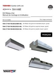
1) Disconnect lead wires and connectors<br />
connected from the control P.C. board<br />
assembly to other parts.<br />
1. Lead wires<br />
• Connection with the power terminal<br />
block: 3 wires (Black, White, Orange)<br />
Take off<br />
earth screws.<br />
• Earth wire: 1 wire (Black)<br />
2. Connectors<br />
• Connection with compressor:<br />
Power line<br />
Remove 3P connector.<br />
• Connection with reactor:<br />
Remove the relay connectors from<br />
P07, 08 (2P, White) and P12, 13<br />
(2P, Yellow)<br />
CN300 : Outdoor fan (3P, White)<br />
CN301 : Position detection (5P, White)<br />
CN701 : 4-way valve (3P, Yellow)<br />
CN600 : TE sensor (2P, White)<br />
CN601 : TD sensor (3P, White)<br />
CN603 : TS sensor (3P, White)<br />
CN602 : TO sensor (3P, White)<br />
CN500 : Case thermo. (2P, White)<br />
CN703 : PMV (6P, White)<br />
Inverter box<br />
(Metal sheet)<br />
Control P.C.<br />
board assembly<br />
P.C. board base<br />
Hooking claws<br />
(4 positions)<br />
2) Remove the inverter box (Metal plate).<br />
3) Remove the control board assembly<br />
from P.C. board base.<br />
(Remove the heat sink and the control<br />
board assembly as they are screwed.)<br />
Control P.C.<br />
board assembly<br />
NOTES:<br />
1. CN300, CN301 and CN701, etc. at the<br />
control board assembly side are connectors<br />
with locking function.<br />
P.C. board base<br />
Therefore, remove the connector while<br />
pushing the part indicated by an arrow mark.<br />
2. Remove 4 hooking claws of P.C. board<br />
base, and remove upward the heat sink<br />
with hands.<br />
4) Take off 3 screws fixing the heat sink<br />
and main control board assembly side,<br />
and replace the board with a new one.<br />
NOTE:<br />
When mounting a new board, check that the<br />
board is correctly set in the groove of the base<br />
holder of P.C. board base.<br />
Attach the P.C. board so that the heat sink<br />
comes securely contact with the metal sheet.<br />
Heat sink<br />
Inverter box<br />
(Metal sheet)<br />
– 207 –
![Service-Handbuch [20522 kB]](https://img.yumpu.com/23967369/1/184x260/service-handbuch-20522-kb.jpg?quality=85)

![Preisliste [3476 kB] - Krüger and Co](https://img.yumpu.com/23967351/1/184x260/preisliste-3476-kb-kra-1-4-ger-and-co.jpg?quality=85)
![Prospekt [1268 kB]](https://img.yumpu.com/23967350/1/184x260/prospekt-1268-kb.jpg?quality=85)
![Mode d'emploi [759 kB]](https://img.yumpu.com/23967349/1/184x260/mode-demploi-759-kb.jpg?quality=85)
![Mode d'emploi [4761 kB]](https://img.yumpu.com/23967346/1/184x260/mode-demploi-4761-kb.jpg?quality=85)