- Page 1 and 2:
SERVICE MANUAL FILE NO. A07-003 Rev
- Page 3 and 4:
7. REFRIGERANT R410A ..............
- Page 5 and 6:
WARNING Check earth wires. Prohibit
- Page 7 and 8:
• New Refrigerant (R410A) This ai
- Page 9 and 10:
1. SPECIFICATIONS Revised 2: Jun.,
- Page 11 and 12:
Revised 2: Jun., 2008 Indoor unit
- Page 13 and 14:
1-1-2. Concealed Duct Type Model I
- Page 15 and 16:
1-1-3. Under Ceiling Type Revised
- Page 17 and 18:
1-1-4. High Wall Type Revised 2: J
- Page 19 and 20:
1-1-5. Compact 4-Way Cassette (600
- Page 21 and 22:
1-1-6. Slim Duct Type Model Coolin
- Page 23 and 24:
Revised 2: Jun., 2008 Indoor unit 1
- Page 25 and 26:
1-2. Outdoor Unit Model name Outdo
- Page 27 and 28:
1-3. Operation Characteristic Curve
- Page 29 and 30:
2. CONSTRUCTION VIEWS (EXTERNAL VIE
- Page 31 and 32:
Revised 2: Jun., 2008 RAV-SM1104UT-
- Page 33 and 34:
- 33 - 365 17.5 17.5 74 Drain hole
- Page 35 and 36:
RAV-TWP30E2, RAV-TWP50E2 (Simultane
- Page 37 and 38:
3-2. Outdoor Unit RAV-SP1104AT-E, S
- Page 39 and 40:
4-1. Slim Duct (Filter Attached) 4.
- Page 41 and 42:
5-1-2. Slim Duct Type RAV-SM404SDT-
- Page 43 and 44:
- 43 - CAUTION : HIGH VOLTAGE The h
- Page 45 and 46:
6-2. Outdoor Unit (Parts Ratings) R
- Page 47 and 48:
Table 7-2-1 Thicknesses of annealed
- Page 49 and 50:
43˚to 45˚ 45˚to 46˚ B A C D Fig
- Page 51 and 52:
1) Be sure to make setting so that
- Page 53 and 54:
7-6. Instructions for Re-use Piping
- Page 55 and 56:
Revised 2: Jun., 2008 7-6-6. Handli
- Page 57 and 58:
7-6-8. Recovery method of refrigera
- Page 59 and 60:
8-1-2. Connection of Wireless Remot
- Page 61 and 62:
8-2. Control Specifications No. Ite
- Page 63 and 64:
No. Item Outline of specifications
- Page 65 and 66:
No. Item Outline of specifications
- Page 67 and 68:
No. Item Outline of specifications
- Page 69 and 70:
No. Item Outline of specifications
- Page 71 and 72:
No. Item Outline of specifications
- Page 73 and 74:
No. Item Outline of specifications
- Page 75 and 76:
Optional power supply CN309 (Yellow
- Page 77 and 78:
- 77 - L-phase power supply lead (B
- Page 79 and 80:
3. Outdoor fan control SP110 SP140
- Page 81 and 82:
7. Current release value shift cont
- Page 83 and 84:
1. Pulse Motor Valve (PMV) control
- Page 85 and 86:
2) Heating fan control The outdoor
- Page 87 and 88:
10-1. Summary of Troubleshooting 1
- Page 89 and 90:
10-2. Troubleshooting 10-2-1. Outli
- Page 91 and 92:
10-2-2. Others (Other than Check Co
- Page 93 and 94:
- 93 - Check Code List (Outdoor) Re
- Page 95 and 96:
Error mode detected by indoor unit
- Page 97 and 98:
Error mode detected by outdoor unit
- Page 99 and 100:
10-2-4. Diagnostic Procedure for Ea
- Page 101 and 102:
Revised 2: Jun., 2008 [E18 error] I
- Page 103 and 104:
[P10 error] Is connection of float
- Page 105 and 106:
[F02 error] Revised 2: Jun., 2008
- Page 107 and 108:
[E03 error] (Master indoor unit) [
- Page 109 and 110:
Check code Outdoor LED display Che
- Page 111 and 112:
Check code Outdoor LED display Che
- Page 113 and 114:
Check code [L29] Outdoor LED displa
- Page 115 and 116:
Check code Outdoor LED display Che
- Page 117 and 118:
Check code Outdoor LED display Che
- Page 119 and 120:
Temperature sensor Temperature - Re
- Page 121 and 122:
Lamp indication Check code Cause of
- Page 123 and 124:
- 123 - Check Code List (Outdoor) R
- Page 125 and 126:
Error mode detected by remote contr
- Page 127 and 128:
10-2-9. Diagnostic Procedure for Ea
- Page 129 and 130:
[E18 error] Is inter-unit cable of
- Page 131 and 132:
[P10 error] Revised 2: Jun., 2008
- Page 133 and 134: [F02 error] Revised 2: Jun., 2008
- Page 135 and 136: [E03 error] (Master indoor unit) [
- Page 137 and 138: Check code [F12] [Suction temp. sen
- Page 139 and 140: Check code [P22] [Fan system error]
- Page 141 and 142: 11. REPLACEMENT OF SERVICE P.C. BOA
- Page 143 and 144: Revised 2: Jun., 2008 Setting 4-way
- Page 145 and 146: Revised 2: Jun., 2008 Table 1. Sett
- Page 147 and 148: 12-1. Indoor Unit 12. SETUP AT LOCA
- Page 149 and 150: Procedure 1 2 Turn on power of the
- Page 151 and 152: 12-1-4. Function Selection Setup P
- Page 153 and 154: DN Item Contents At shipment from f
- Page 155 and 156: 12-1-6. Monitor Function of Remote
- Page 157 and 158: n Indoor unit power-ON sequence Pow
- Page 159 and 160: 4. Wiring specifications • Use 2-
- Page 161 and 162: 2. How to confirm the central contr
- Page 163 and 164: 4. How to set louver lock (Louver f
- Page 165 and 166: Be sure to make ceiling setting whe
- Page 167 and 168: 12-4-3. Service Support Function (L
- Page 169 and 170: 2) Error display The error which i
- Page 171 and 172: 4) Specific operation for maintenan
- Page 173 and 174: 13. ADDRESS SETUP Revised 2: Jun.,
- Page 175 and 176: 13-2-2. Automatic Address Example f
- Page 177 and 178: Revised 2: Jun., 2008 13-3. Remote
- Page 179 and 180: 13-5. Confirmation of Indoor Unit N
- Page 181 and 182: 14. DETACHMENTS Revised 2: Jun., 20
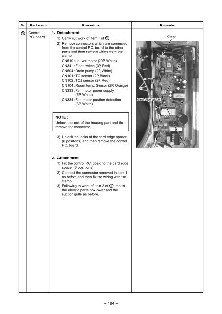
- Page 183: No. Part name Procedure Remarks 4 C
- Page 187 and 188: No. Part name Procedure Remarks 7 F
- Page 189 and 190: No. Part name Procedure Remarks 9 F
- Page 191 and 192: 14-1-2. Slim Duct Type RAV-SM404SDT
- Page 193 and 194: No. Part name Procedure Remarks 5 P
- Page 195 and 196: No. Part name Procedure Remarks 9 D
- Page 197 and 198: No. Part name Procedure Remarks 2 D
- Page 199 and 200: No. Part name Procedure Remarks 4 R
- Page 201 and 202: No. Part name Procedure Remarks 6 C
- Page 203 and 204: No. Part name Procedure Remarks 7 P
- Page 205 and 206: No. Part name Procedure Remarks 2 F
- Page 207 and 208: No. Part name Procedure Remarks 4 C
- Page 209 and 210: No. Part name Procedure Remarks 7 C
- Page 211 and 212: 15. EXPLODED VIEWS AND PARTS LIST R
- Page 213 and 214: RAV-SM564UT-E, RAV-SM804UT-E, RAV-S
- Page 215 and 216: RBC-AX31U (W)-E, RBC-AX31U (WS)-E 3
- Page 217 and 218: Revised 2: Jun., 2008 Location No.
- Page 219 and 220: 15-2. Outdoor Unit RAV-SP1104AT-E,
- Page 221 and 222: RAV-SP1104AT-E, RAV-SP1104ATZ-E, RA
- Page 223 and 224: Location No. Part No. Description 1
- Page 225 and 226: WARNINGS ON REFRIGERANT LEAKAGE Che


![Service-Handbuch [20522 kB]](https://img.yumpu.com/23967369/1/184x260/service-handbuch-20522-kb.jpg?quality=85)
![Preisliste [3476 kB] - Krüger and Co](https://img.yumpu.com/23967351/1/184x260/preisliste-3476-kb-kra-1-4-ger-and-co.jpg?quality=85)
![Prospekt [1268 kB]](https://img.yumpu.com/23967350/1/184x260/prospekt-1268-kb.jpg?quality=85)
![Mode d'emploi [759 kB]](https://img.yumpu.com/23967349/1/184x260/mode-demploi-759-kb.jpg?quality=85)
![Mode d'emploi [4761 kB]](https://img.yumpu.com/23967346/1/184x260/mode-demploi-4761-kb.jpg?quality=85)