RAS-M18UAV-E
RAS-M18UAV-E
RAS-M18UAV-E

You also want an ePaper? Increase the reach of your titles
YUMPU automatically turns print PDFs into web optimized ePapers that Google loves.
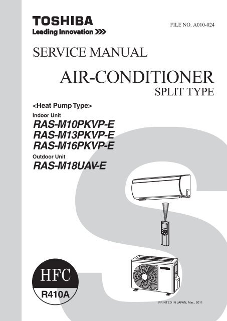
FILE NO. A010-024<br />
SERVICE MANUAL<br />
<br />
Indoor Unit<br />
<strong>RAS</strong>-M10PKVP-E<br />
<strong>RAS</strong>-M13PKVP-E<br />
<strong>RAS</strong>-M16PKVP-E<br />
Outdoor Unit<br />
AIR-CONDITIONER<br />
<strong>RAS</strong>-<strong>M18UAV</strong>-E<br />
SPLIT TYPE<br />
R410A<br />
PRINTED IN JAPAN, Mar., 2011
CONTENTS<br />
1.<br />
2.<br />
3.<br />
4.<br />
5.<br />
6.<br />
7.<br />
8.<br />
9.<br />
10.<br />
11.<br />
12.<br />
13.<br />
SAFETY PRECAUTIONS ........................................................................ 3<br />
SPECIFICATIONS .................................................................................... 5<br />
REFRIGERANT R410A ............................................................................ 9<br />
CONSTRUCTION VIEWS ...................................................................... 17<br />
WIRING DIAGRAM ................................................................................ 19<br />
SPECIFICATIONS OF ELECTRICAL PARTS ....................................... 21<br />
REFRIGERANT CYCLE DIAGRAM ...................................................... 22<br />
CONTROL BLOCK DIAGRAM .............................................................. 24<br />
OPERATION DESCRIPTION ................................................................. 26<br />
INSTALLATION PROCEDURE .............................................................. 52<br />
HOW TO DIAGNOSE THE TROUBLE .................................................. 72<br />
HOW TO REPLACE THE MAIN PARTS ............................................... 94<br />
EXPLODED VIEWS AND PARTS LIST ............................................... 110<br />
– 2 –
1.<br />
SAFETY PRECAUTIONS<br />
For general public use<br />
Power supply cord of outdoor unit shall be more than 1.5 mm ² (H07RN-F or 245IEC66) polychloroprene<br />
sheathed fl exible cord.<br />
• Read this “SAFETY PRECAUTIONS” carefully before servicing.<br />
• The precautions described below include the important items regarding safety. Observe them without fail.<br />
• After the servicing work, perform a trial operation to check for any problem.<br />
• Turn off the main power supply switch (or breaker) before the unit maintenance.<br />
CAUTION<br />
New Refrigerant Air Conditioner Installation<br />
• THIS AIR CONDITIONER ADOPTS THE NEW HFC REFRIGERANT (R410A) WHICH DOES NOT<br />
DESTROY OZONE LAYER.<br />
R410A refrigerant is apt to be affected by impurities such as water, oxidizing membrane, and oils because<br />
the working pressure of R410A refrigerant is approx. 1.6 times of refrigerant R22.<br />
Accompanied with the adoption of the new refrigerant, the refrigeration machine oil has also been changed.<br />
Therefore, during installation work, be sure that water, dust, former refrigerant, or refrigeration machine oil<br />
does not enter into the new type refrigerant R410A air conditioner circuit.<br />
To prevent mixing of refrigerant or refrigerating machine oil, the sizes of connecting sections of charging port<br />
on main unit and installation tools are different from those used for the conventional refrigerant units.<br />
Accordingly, special tools are required for the new refrigerant (R410A) units.<br />
For connecting pipes, use new and clean piping materials with high pressure fi ttings made for R410A only,<br />
so that water and/or dust does not enter. Moreover, do not use the existing piping because there are some<br />
problems with pressure fi ttings and possible impurities in existing piping.<br />
CAUTION<br />
TO DISCONNECT THE APPLIANCE FROM THE MAIN POWER SUPPLY<br />
This appliance must be connected to the main power supply by a circuit breaker or a switch with a contact<br />
separation of at least 3 mm.<br />
DANGER<br />
• THE MANUFACTURER SHALL NOT ASSUME ANY LIABILITY FOR THE DAMAGE CAUSED BY<br />
NOT OBSERVING THE DESCRIPTION OF THIS MANUAL.<br />
• ASK AN AUTHORIZED DEALER OR QUALIFIED INSTALLATION PROFESSIONAL TO INSTALL/<br />
MAINTAIN THE AIR CONDITIONER.<br />
INAPPROPRIATE SERVICING MAY RESULT IN WATER LEAKAGE, ELECTRIC SHOCK OR FIRE.<br />
• TURN OFF MAIN POWER SUPPLY BEFORE ATTEMPTING ANY ELECTRICAL WORK. MAKE SURE<br />
ALL POWER SWITCHES ARE OFF. FAILURE TO DO SO MAY CAUSE ELECTRIC SHOCK.<br />
DANGER: HIGH VOLTAGE<br />
The high voltage circuit is incorporated.<br />
Be careful to do the check service, as the electric shock may be caused in case of touching parts on<br />
the P.C. board by hand.<br />
• CORRECTLY CONNECT THE CONNECTING CABLE. IF THE CONNECTING CABLE IS INCORRECTLY<br />
CONNECTED, ELECTRIC PARTS MAY BE DAMAGED.<br />
• CHECK THAT THE EARTH WIRE IS NOT BROKEN OR DISCONNECTED BEFORE SERVICE AND<br />
INSTALLATION. FAILURE TO DO SO MAY CAUSE ELECTRIC SHOCK.<br />
– 3 –
• DO NOT INSTALL NEAR CONCENTRATIONS OF COMBUSTIBLE GAS OR GAS VAPORS. FAILURE<br />
TO FOLLOW THIS INSTRUCTION CAN RESULT IN FIRE OR EXPLOSION.<br />
• TO PREVENT THE INDOOR UNIT FROM OVERHEATING AND CAUSING A FIRE HAZARD, PLACE<br />
THE UNIT WELL AWAY (MORE THAN 2 M) FROM HEAT SOURCES SUCH AS RADIATORS, HEAT<br />
RESISTORS, FURNACE, STOVES, ETC.<br />
• WHEN MOVING THE AIR-CONDITIONER FOR INSTALLATION IN ANOTHER PLACE, BE VERY<br />
CAREFUL NOT TO ALLOW THE SPECIFIED REFRIGERANT (R410A) TO BECOME MIXED WITH<br />
ANY OTHER GASEOUS BODY INTO THE REFRIGERATION CIRCUIT. IF AIR OR ANY OTHER GAS<br />
IS MIXED IN THE REFRIGERANT, THE GAS PRESSURE IN THE REFRIGERATION CIRCUIT WILL<br />
BECOME ABNORMALLY HIGH AND IT MAY RESULT IN THE PIPE BURSTING AND POSSIBLE<br />
PERSONNEL INJURIES.<br />
• IN THE EVENT THAT THE REFRIGERANT GAS LEAKS OUT OF THE PIPE DURING THE SERVICE<br />
WORK AND THE INSTALLATION WORK, IMMEDIATELY LET FRESH AIR INTO THE ROOM. IF THE<br />
REFRIGERANT GAS IS HEATED, SUCH AS BY FIRE, GENERATION OF POISONOUS GAS MAY RESULT.<br />
WARNING<br />
• Do not use any refrigerant different from the one specified for complement or replacement.<br />
Otherwise, abnormally high pressure may be generated in the refrigeration cycle, which may result in a<br />
failure or explosion of the product or an injury to your body.<br />
• Never modify this unit by removing any of the safety guards or bypass any of the safety<br />
interlock switches.<br />
• Do not install in a place which cannot bear the weight of the unit. Personal injury and property<br />
damage can result if the unit falls.<br />
• After the installation work, confirm that refrigerant gas does not leak.<br />
If refrigerant gas leaks into the room and fl ows near a fi re source such as a cooking range, noxious gas<br />
may generate.<br />
• The electrical work must be performed by a qualified electrician in accordance with the<br />
Installation Manual. Make sure the air conditioner uses an exclusive circuit.<br />
An insuffi cient circuit capacity or inappropriate installation may cause fi re.<br />
• When wiring, use the specified cables and connect the terminals securely to prevent external<br />
forces applied to the cable from affecting the terminals.<br />
• Be sure to provide grounding.<br />
Do not connect ground wires to gas pipes, water pipes, lightning rods or ground wires for telephone cables.<br />
• Conform to the regulations of the local electric company when wiring the power supply.<br />
Inappropriate grounding may cause electric shock.<br />
CAUTION<br />
• Exposure of unit to water or other moisture before installation may result in an electrical short.<br />
Do not store in a wet basement or expose to rain or water.<br />
• Do not install in a place that can increase the vibration of the unit. Do not install in a place that can amplify<br />
the noise level of the unit or where noise or discharged air might disturb neighbors.<br />
• To avoid personal injury, be careful when handling parts with sharp edges.<br />
• Perform the specified installation work to guard against an earthquake.<br />
If the air conditioner is not installed appropriately, accidents may occur due to the falling unit.<br />
For Reference:<br />
If a heating operation would be continuously performed for a long time under the condition that the outdoor<br />
temperature is 0°C or lower, drainage of defrosted water may be diffi cult due to freezing of the bottom plate,<br />
resulting in a trouble of the cabinet or fan.<br />
It is recommended to procure an antifreeze heater locally for a safe installation of the air conditioner.<br />
For details, contact the dealer.<br />
– 4 –
2.<br />
SPECIFICATIONS<br />
The indoor and outdoor units that can be used in combination are shown in the tables below.<br />
Table of models that can be connected<br />
Type Outdoor unit Indoor unit<br />
<strong>RAS</strong>-M10PKVP-E <strong>RAS</strong>-M13PKVP-E <strong>RAS</strong>-M16PKVP-E<br />
<strong>RAS</strong>-M10PKVP-ND <strong>RAS</strong>-M13PKVP-ND <strong>RAS</strong>-M16PKVP-ND<br />
Heat pump <strong>RAS</strong>-<strong>M18UAV</strong>-E<br />
<strong>RAS</strong>-B10UFV-E <strong>RAS</strong>-B13UFV-E<br />
<strong>RAS</strong>-M07SKV-E <strong>RAS</strong>-M10SKV-E <strong>RAS</strong>-M13SKV-E <strong>RAS</strong>-M16SKV-E<br />
<strong>RAS</strong>-M10GDV-E <strong>RAS</strong>-M13GDV-E <strong>RAS</strong>-M16GDV-E<br />
<strong>RAS</strong>-M10SMUV-E <strong>RAS</strong>-M13SMUV-E <strong>RAS</strong>-M16SMUV-E<br />
Table of models that can be used in combination<br />
Type Outdoor unit Combinations of indoor unit models that can be connected<br />
Heat pump <strong>RAS</strong>-<strong>M18UAV</strong>-E 07 + 07, 07 + 10, 07 + 13, 07 +16, 10 + 10, 10 + 13, 10 + 16, 13 + 13, 13+ 16<br />
NOTES<br />
A 1-room connection is not an option for the indoor units (you cannot connect only one indoor unit).<br />
A 2-room connection must always be used for the indoor units (you must connect two indoor units).<br />
With the <strong>RAS</strong>-<strong>M18UAV</strong>-E outdoor unit model, the 16 + 16 combination is not an option.<br />
The contents noted in this service manual limit the indoor units to the <strong>RAS</strong>-M10PKVP-E, <strong>RAS</strong>-M13PKVP-E,<br />
<strong>RAS</strong>-M16PKVP-E.<br />
For other indoor units that can also be used in combination, see the service manual of each indoor unit.<br />
Indoor unit<br />
<strong>RAS</strong>-M07SKV-E<br />
<strong>RAS</strong>-M10SKV-E<br />
<strong>RAS</strong>-M13SKV-E<br />
<strong>RAS</strong>-M16SKV-E<br />
<strong>RAS</strong>-M10GDV-E<br />
<strong>RAS</strong>-M13GDV-E<br />
<strong>RAS</strong>-M16GDV-E<br />
<strong>RAS</strong>-B10UFV-E<br />
<strong>RAS</strong>-B13UFV-E<br />
<strong>RAS</strong>-M10SMUV-E<br />
<strong>RAS</strong>-M13SMUV-E<br />
<strong>RAS</strong>-M16SMUV-E<br />
File No.<br />
SVM-07034<br />
A05-010<br />
SVM-10044<br />
A06-015<br />
– 5 –
2-1. Specifications<br />
<br />
<strong>RAS</strong>-M10PKVP-E, <strong>RAS</strong>-M13PKVP-E, <strong>RAS</strong>-M16PKVP-E / <strong>RAS</strong>-<strong>M18UAV</strong>-E<br />
Unit model<br />
Indoor<br />
<strong>RAS</strong>-M10PKVP-E, <strong>RAS</strong>-M13PKVP-E, <strong>RAS</strong>-M16PKVP-E<br />
Outdoor<br />
<strong>RAS</strong>-<strong>M18UAV</strong>-E<br />
Cooling capacity (kW) 5.2<br />
Cooling capacity range (kW) 1.4 – 6.2<br />
Heating capacity (kW) 5.6<br />
Heating capacity range (kW) 0.9 – 8.3<br />
Power supply<br />
220–240 V – 1 Ph – 50Hz / 220 V – 1 Ph –60Hz<br />
Unit model <strong>RAS</strong>-M10PKVP-E <strong>RAS</strong>-M13PKVP-E <strong>RAS</strong>-M16PKVP-E<br />
Indoor<br />
Running current (A) 0.21 / 0.20 / 0.19 0.24 / 0.23 / 0.22 0.27 / 0.26 / 0.25<br />
(220V/230V/240V) Power consumption (W) 25 30 35<br />
Power factor (%) 54 / 54 / 55 57 / 57 / 57 59 / 59 / 58<br />
Electric<br />
characteristics<br />
Outdoor<br />
(220V/230V/240V)<br />
Operation mode Cooling Heating<br />
Running current (A) 7.12/6.80/6.50 8.28/7.91/7.57<br />
Power consumption (W) 1540 1790<br />
Power factor (%) 98 98<br />
Starting current (A) 7.42/7.10/6.80<br />
COP (Cooling/Heating) 3.61/4.71<br />
Operating noise<br />
Indoor<br />
(Cooling/Heating)<br />
Unit model <strong>RAS</strong>-M10PKVP-E <strong>RAS</strong>-M13PKVP-E <strong>RAS</strong>-M16PKVP-E<br />
High (dB•A) 43 / 43 45 / 45 47 / 47<br />
Medium (dB•A) 37 / 35 38 / 36 40 / 38<br />
Low (dB•A) 31 / 27 31 / 27 34 / 30<br />
Outdoor<br />
(Cooling/Heating)<br />
2 indoor units operating (dB•A) 49/51<br />
Unit model <strong>RAS</strong>-M10PKVP-E <strong>RAS</strong>-M13PKVP-E <strong>RAS</strong>-M16PKVP-E<br />
Height (mm) 295 295 295<br />
Dimension<br />
Width (mm) 790 790 790<br />
Indoor unit<br />
Depth (mm) 242 242 242<br />
Net weight (kg) 12 12 12<br />
Fan motor output (W) 30 30 30<br />
Air fl ow rate (Cooling/Heating) (m³/h) 640 / 640 690 / 690 750 / 750<br />
Height (mm) 550<br />
Dimension<br />
Width (mm) 780<br />
Depth (mm) 290<br />
Net weight (kg) 41<br />
Outdoor unit<br />
Motor output (W) 1100<br />
Compressor<br />
Type<br />
Twin rotary type with DC-inverter variable speed control<br />
Model<br />
DA130A1F-25F<br />
Fan motor output (W) 43<br />
Air fl ow rate (m³/h) 2300/2400<br />
Type<br />
Flare connection<br />
Indoor unit<br />
Unit model <strong>RAS</strong>-M10PKVP-E <strong>RAS</strong>-M13PKVP-E <strong>RAS</strong>-M16PKVP-E<br />
Liquid side/Gas side Ø6.35/ Ø9.52 Ø6.35/ Ø9.52 Ø6.35/ Ø12.7<br />
Outdoor unit Liquid side/Gas side Ø6.35/ Ø9.52<br />
Maximum length (per unit) (m) 20<br />
Piping connection<br />
Maximum length (total) (m) 30<br />
Maximum chargeless length (total) (m) 20<br />
Maximum height difference (m) 10<br />
Additional refrigerant 20g/m (pipe length 21m to 30m)<br />
Name of refrigerant<br />
R410A<br />
Weight (kg) 1.20<br />
Wiring connection<br />
Power supply<br />
3 Wires : includes earth<br />
Interconnection<br />
4 Wires : includes earth<br />
Usable temperature range<br />
Indoor (Cooling/Heating) (°C) 21 to 32/0 to 27<br />
Outdoor (Cooling/Heating) (°C) 5 to 43/–15 to 24<br />
Unit model <strong>RAS</strong>-M10PKVP-E <strong>RAS</strong>-M13PKVP-E <strong>RAS</strong>-M16PKVP-E<br />
Installation plate 1 1 1<br />
Wireless remote controller 1 1 1<br />
Batteries 2 2 2<br />
Indoor unit Remote controller holder 1 1 1<br />
Accessory<br />
Remote controller holder mounting screw 2 (Ø3.1 × 16L) 2 (Ø3.1 × 16L) 2 (Ø3.1 × 16L)<br />
Owner’s manual 1 1 1<br />
Mounting screw 6 (Ø4 × 25L) 6 (Ø4 × 25L) 6 (Ø4 × 25L)<br />
Installation manual 1 1 1<br />
Installation manual 1<br />
Outdoor unit Drain nipple 1<br />
Water-proof rubber cap 2<br />
• For performance when each indoor unit is combined with other unit, refer to the separate table.<br />
• The specifi cations may be subject to change without notice for purpose of improvement.<br />
– 6 –
2-2. Performance Specifications Combinations of Indoor Unit<br />
<strong>RAS</strong>-<strong>M18UAV</strong>-E<br />
Operation<br />
mode<br />
Cooling<br />
Volts<br />
V<br />
220<br />
230<br />
240<br />
Operation<br />
status<br />
1 unit<br />
2 units<br />
1 unit<br />
2 units<br />
1 unit<br />
2 units<br />
<strong>RAS</strong>-<strong>M18UAV</strong>-E<br />
Operation<br />
mode<br />
Heating<br />
Volts<br />
V<br />
220<br />
230<br />
240<br />
Operation<br />
status<br />
1 unit<br />
2 units<br />
1 unit<br />
2 units<br />
1 unit<br />
2 units<br />
Operating indoor unit Unit capacity (kW) Capacity<br />
Running current Power Consumption<br />
A B A B<br />
kW<br />
A<br />
W<br />
07 — 2.0 — 2.0 (1.1 to 3.0) 2.40 (1.43 to 3.83) 460 (220 to 800)<br />
10 — 2.7 — 2.7 (1.1 to 3.2) 3.25 (1.43 to 3.83) 630 (220 to 800)<br />
13 — 3.7 — 3.7 (1.1 to 4.2) 5.21 (1.43 to 6.49) 1100 (220 to 1400)<br />
16 — 4.5 — 4.5 (1.1 to 4.9) 7.03 (1.43 to 7.88) 1500 (220 to 1700)<br />
07 07 2.00 2.00 4.0 (1.4 to 4.8) 4.69 (1.68 to 9.97) 960 (260 to 2150)<br />
10 07 2.65 1.95 4.6 (1.4 to 6.0) 5.87 (1.68 to 9.97) 1200 (260 to 2150)<br />
10 10 2.55 2.55 5.1 (1.4 to 6.1) 6.75 (1.68 to 9.97) 1410 (260 to 2150)<br />
13 07 3.38 1.82 5.2 (1.4 to 6.1) 6.75 (1.68 to 10.06) 1440 (260 to 2170)<br />
13 10 3.00 2.20 5.2 (1.4 to 6.2) 6.75 (1.68 to 10.06) 1440 (260 to 2170)<br />
16 07 3.60 1.60 5.2 (1.4 to 6.2) 6.75 (1.68 to 10.06) 1440 (260 to 2170)<br />
16 10 3.25 1.95 5.2 (1.4 to 6.2) 6.75 (1.68 to 10.06) 1440 (260 to 2170)<br />
13 13 2.60 2.60 5.2 (1.4 to 6.2) 6.75 (1.68 to 10.06) 1440 (260 to 2170)<br />
16 13 2.85 2.35 5.2 (1.4 to 6.2) 6.75 (1.68 to 10.06) 1440 (260 to 2170)<br />
07 — 2.0 — 2.0 (1.1 to 3.0) 2.30 (1.37 to 3.66) 460 (220 to 800)<br />
10 — 2.7 — 2.7 (1.1 to 3.2) 3.10 (1.37 to 3.66) 630 (220 to 800)<br />
13 — 3.7 — 3.7 (1.1 to 4.2) 5.00 (1.37 to 6.21) 1100 (220 to 1400)<br />
16 — 4.5 — 4.5 (1.1 to 4.9) 6.70 (1.37 to 7.23) 1500 (220 to 1700)<br />
07 07 2.00 2.00 4.0 (1.4 to 4.8) 4.50 (1.61 to 9.54) 960 (260 to 2150)<br />
10 07 2.65 1.95 4.6 (1.4 to 6.0) 5.61 (1.61 to 9.54) 1200 (260 to 2150)<br />
10 10 2.55 2.55 5.1 (1.4 to 6.1) 6.45 (1.61 to 9.54) 1410 (260 to 2150)<br />
13 07 3.38 1.82 5.2 (1.4 to 6.1) 6.45 (1.61 to 9.63) 1440 (260 to 2170)<br />
13 10 3.00 2.20 5.2 (1.4 to 6.2) 6.45 (1.61 to 9.63) 1440 (260 to 2170)<br />
16 07 3.60 1.60 5.2 (1.4 to 6.2) 6.45 (1.61 to 9.63) 1440 (260 to 2170)<br />
16 10 3.25 1.95 5.2 (1.4 to 6.2) 6.45 (1.61 to 9.63) 1440 (260 to 2170)<br />
13 13 2.60 2.60 5.2 (1.4 to 6.2) 6.45 (1.61 to 9.63) 1440 (260 to 2170)<br />
16 13 2.85 2.35 5.2 (1.4 to 6.2) 6.45 (1.61 to 9.63) 1440 (260 to 2170)<br />
07 — 2.0 — 2.0 (1.1 to 3.0) 2.20 (1.31 to 3.51) 460 (220 to 800)<br />
10 — 2.7 — 2.7 (1.1 to 3.2) 2.98 (1.31 to 3.51) 630 (220 to 800)<br />
13 — 3.7 — 3.7 (1.1 to 4.2) 4.77 (1.31 to 5.95) 1100 (220 to 1400)<br />
16 — 4.5 — 4.5 (1.1 to 4.9) 6.44 (1.31 to 7.23) 1500 (220 to 1700)<br />
07 07 2.00 2.00 4.0 (1.4 to 4.8) 4.30 (1.55 to 9.14) 960 (260 to 2150)<br />
10 07 2.65 1.95 4.6 (1.4 to 6.0) 5.38 (1.55 to 9.14) 1200 (260 to 2150)<br />
10 10 2.55 2.55 5.1 (1.4 to 6.1) 6.18 (1.55 to 9.14) 1410 (260 to 2150)<br />
13 07 3.38 1.82 5.2 (1.4 to 6.1) 6.19 (1.55 to 9.23) 1440 (260 to 2170)<br />
13 10 3.00 2.20 5.2 (1.4 to 6.2) 6.19 (1.55 to 9.23) 1440 (260 to 2170)<br />
16 07 3.60 1.60 5.2 (1.4 to 6.2) 6.19 (1.55 to 9.23) 1440 (260 to 2170)<br />
16 10 3.25 1.95 5.2 (1.4 to 6.2) 6.19 (1.55 to 9.23) 1440 (260 to 2170)<br />
13 13 2.60 2.60 5.2 (1.4 to 6.2) 6.19 (1.55 to 9.23) 1440 (260 to 2170)<br />
16 13 2.85 2.35 5.2 (1.4 to 6.2) 6.19 (1.55 to 9.23) 1440 (260 to 2170)<br />
Operating indoor unit Unit capacity (kW) Capacity<br />
Running current Power Consumption<br />
A B A B<br />
kW<br />
A<br />
W<br />
07 — 2.7 — 2.7 (0.7 to 4.8) 3.65 (1.10 to 7.88) 730 (170 to 1700)<br />
10 — 4.0 — 4.0 (0.7 to 5.2) 5.62 (1.10 to 7.88) 1200 (170 to 1700)<br />
13 — 5.0 — 5.0 (0.7 to 6.5) 8.43 (1.10 to 11.73) 1800 (170 to 2530)<br />
16 — 5.5 — 5.5 (0.7 to 6.9) 8.90 (1.10 to 11.73) 1900 (170 to 2530)<br />
07 07 2.70 2.70 5.4 (0.9 to 8.0) 5.58 (1.30 to 11.62) 1190 (200 to 2480)<br />
10 07 3.79 1.61 5.4 (0.9 to 8.2) 5.58 (1.30 to 11.73) 1190 (200 to 2530)<br />
10 10 2.70 2.70 5.4 (0.9 to 8.2) 5.58 (1.30 to 11.73) 1190 (200 to 2530)<br />
13 07 3.64 1.96 5.6 (0.9 to 8.2) 5.58 (1.30 to 11.73) 1190 (200 to 2530)<br />
13 10 3.11 2.49 5.6 (0.9 to 8.3) 5.58 (1.30 to 11.73) 1190 (200 to 2530)<br />
16 07 3.76 1.84 5.6 (0.9 to 8.3) 5.58 (1.30 to 11.73) 1190 (200 to 2530)<br />
16 10 3.24 2.36 5.6 (0.9 to 8.3) 5.58 (1.30 to 11.73) 1190 (200 to 2530)<br />
13 13 2.80 2.80 5.6 (0.9 to 8.3) 5.58 (1.30 to 11.73) 1190 (200 to 2530)<br />
16 13 2.93 2.67 5.6 (0.9 to 8.3) 5.58 (1.30 to 11.73) 1190 (200 to 2530)<br />
07 — 2.7 — 2.7 (0.7 to 4.8) 3.50 (1.06 to 7.54) 730 (170 to 1700)<br />
10 — 4.0 — 4.0 (0.7 to 5.2) 5.40 (1.06 to 7.54) 1200 (170 to 1700)<br />
13 — 5.0 — 5.0 (0.7 to 6.5) 8.10 (1.06 to 11.22) 1800 (170 to 2530)<br />
16 — 5.5 — 5.5 (0.7 to 6.9) 8.50 (1.06 to 11.22) 1900 (170 to 2530)<br />
07 07 2.70 2.70 5.4 (0.9 to 8.0) 5.35 (1.24 to 11.12) 1190 (200 to 2480)<br />
10 07 3.79 1.61 5.4 (0.9 to 8.2) 5.35 (1.24 to 11.22) 1190 (200 to 2530)<br />
10 10 2.70 2.70 5.4 (0.9 to 8.2) 5.35 (1.24 to 11.22) 1190 (200 to 2530)<br />
13 07 3.64 1.96 5.6 (0.9 to 8.2) 5.35 (1.24 to 11.22) 1190 (200 to 2530)<br />
13 10 3.11 2.49 5.6 (0.9 to 8.3) 5.35 (1.24 to 11.22) 1190 (200 to 2530)<br />
16 07 3.76 1.84 5.6 (0.9 to 8.3) 5.35 (1.24 to 11.22) 1190 (200 to 2530)<br />
16 10 3.24 2.36 5.6 (0.9 to 8.3) 5.35 (1.24 to 11.22) 1190 (200 to 2530)<br />
13 13 2.80 2.80 5.6 (0.9 to 8.3) 5.35 (1.24 to 11.22) 1190 (200 to 2530)<br />
16 13 2.93 2.67 5.6 (0.9 to 8.3) 5.35 (1.24 to 11.22) 1190 (200 to 2530)<br />
07 — 2.7 — 2.7 (0.7 to 4.8) 3.34 (1.01 to 7.23) 730 (170 to 1700)<br />
10 — 4.0 — 4.0 (0.7 to 5.2) 5.15 (1.01 to 7.23) 1200 (170 to 1700)<br />
13 — 5.0 — 5.0 (0.7 to 6.5) 7.73 (1.01 to 10.76) 1800 (170 to 2530)<br />
16 — 5.5 — 5.5 (0.7 to 6.9) 8.16 (1.01 to 10.76) 1900 (170 to 2530)<br />
07 07 2.70 2.70 5.4 (0.9 to 8.0) 5.11 (1.19 to 10.65) 1190 (200 to 2480)<br />
10 07 3.79 1.61 5.4 (0.9 to 8.2) 5.11 (1.19 to 10.76) 1190 (200 to 2530)<br />
10 10 2.70 2.70 5.4 (0.9 to 8.2) 5.11 (1.19 to 10.76) 1190 (200 to 2530)<br />
13 07 3.64 1.96 5.6 (0.9 to 8.2) 5.11 (1.19 to 10.76) 1190 (200 to 2530)<br />
13 10 3.11 2.49 5.6 (0.9 to 8.3) 5.11 (1.19 to 10.76) 1190 (200 to 2530)<br />
16 07 3.76 1.84 5.6 (0.9 to 8.3) 5.11 (1.19 to 10.76) 1190 (200 to 2530)<br />
16 10 3.24 2.36 5.6 (0.9 to 8.3) 5.11 (1.19 to 10.76) 1190 (200 to 2530)<br />
13 13 2.80 2.80 5.6 (0.9 to 8.3) 5.11 (1.19 to 10.76) 1190 (200 to 2530)<br />
16 13 2.93 2.67 5.6 (0.9 to 8.3) 5.11 (1.19 to 10.76) 1190 (200 to 2530)<br />
The above specifi cation values are those under the conditions. Cooling Indoor: DB/WB=27/19°C Heating Indoor: DB=20°C<br />
Outdoor: DB=35°C<br />
Outdoor: DB/WB=7/6°C<br />
– 7 –
2-2-1 Operation Characteristic Curve<br />
<strong>RAS</strong>-<strong>M18UAV</strong>-E<br />
<br />
12<br />
11<br />
<br />
12<br />
11<br />
Current (A)<br />
10<br />
9<br />
8<br />
7<br />
6<br />
5<br />
• Conditions<br />
Indoor : DB 27˚C/WB 19˚C<br />
Outdoor : DB 35˚C<br />
Air flow : High<br />
Pipe length : 7.5m × 2<br />
2 units operating<br />
230V<br />
Current (A)<br />
10<br />
9<br />
8<br />
7<br />
6<br />
5<br />
4<br />
3<br />
2<br />
1<br />
4<br />
3<br />
2<br />
1<br />
• Conditions<br />
Indoor : DB 20˚C<br />
Outdoor : DB 7˚C/WB 6˚C<br />
Air flow : High<br />
Pipe length : 7.5m × 2<br />
2 units oper<br />
230V<br />
0<br />
0 10 20 30 40 50 60 70 80 90<br />
0 0 20 40 60 80 100 120 140<br />
Compressor speed (rps)<br />
2-2-2 Capacity Variation Ratio According to Temperature<br />
Compressor speed (rps)<br />
<strong>RAS</strong>-<strong>M18UAV</strong>-E<br />
<br />
115<br />
<br />
105<br />
110<br />
105<br />
• Conditions<br />
Indoor : DB 27˚C<br />
Outdoor : DB 35˚C<br />
Indoor air flow : High<br />
Pipe length : 7.5m × 2<br />
2 units operating<br />
100<br />
95<br />
90<br />
Capacity ratio (%)<br />
100<br />
95<br />
Capacity ratio (%)<br />
85<br />
80<br />
75<br />
70<br />
90<br />
65<br />
85<br />
60<br />
55<br />
• Conditions<br />
Indoor : DB 27˚C/WB 19˚C<br />
Indoor air flow : High<br />
Pipe length : 7.5m × 2<br />
2 units operating<br />
0<br />
14 16 18 20 22 24<br />
Indoor air wet bulb temp. (˚C)<br />
50<br />
32 33 34 35 36 37 38 39 40 41 42 43<br />
Outdoor temp. (˚C)<br />
Capacity ratio : 100% = 5.2 kW<br />
– 8 –
3.<br />
REFRIGERANT R410A<br />
This air conditioner adopts the new refrigerant HFC<br />
(R410A) which does not damage the ozone layer.<br />
The working pressure of the new refrigerant R410A<br />
is 1.6 times higher than conventional refrigerant<br />
(R22). The refrigerating oil is also changed in<br />
accordance with change of refrigerant, so be<br />
careful that water, dust, and existing refrigerant or<br />
refrigerating oil are not entered in the refrigerant<br />
cycle of the air conditioner using the new refrigerant<br />
during installation work or servicing time.<br />
The next section describes the precautions for air<br />
conditioner using the new refrigerant.<br />
Conforming to contents of the next section together<br />
with the general cautions included in this manual,<br />
perform the correct and safe work.<br />
3-1. Safety During Installation/Servicing<br />
As R410A’s pressure is about 1.6 times higher than<br />
that of R22, improper installation/servicing may<br />
cause a serious trouble.<br />
By using tools and materials exclusive for R410A,<br />
it is necessary to carry out installation/servicing<br />
safely while taking the following precautions into<br />
consideration.<br />
1. Never use refrigerant other than R410A in an air<br />
conditioner which is designed to operate with<br />
R410A.<br />
If other refrigerant than R410A is mixed, pressure<br />
in the refrigeration cycle becomes abnormally<br />
high, and it may cause personal injury, etc. by a<br />
rupture.<br />
2. Confi rm the used refrigerant name, and use tools<br />
and materials exclusive for the refrigerant R410A.<br />
The refrigerant name R410A is indicated on<br />
the visible place of the outdoor unit of the air<br />
conditioner using R410A as refrigerant. To<br />
prevent mischarging, the diameter of the service<br />
port differs from that of R22.<br />
3. If a refrigeration gas leakage occurs during<br />
installation/servicing, be sure to ventilate fully.<br />
If the refrigerant gas comes into contact with fi re,<br />
a poisonous gas may occur.<br />
4. When installing or removing an air conditioner,<br />
do not allow air or moisture to remain in the<br />
refrigeration cycle.<br />
Otherwise, pressure in the refrigeration cycle<br />
may become abnormally high so that a rupture or<br />
personal injury may be caused.<br />
5. After completion of installation work, check to<br />
make sure that there is no refrigeration gas<br />
leakage.<br />
If the refrigerant gas leaks into the room, coming<br />
into contact with fi re in the fan-driven heater,<br />
space heater, etc., a poisonous gas may occur.<br />
6. When an air conditioning system charged with a<br />
large volume of refrigerant is installed in a small<br />
room, it is necessary to exercise care so that,<br />
even when refrigerant leaks, its concentration<br />
does not exceed the marginal level.<br />
If the refrigerant gas leakage occurs and its<br />
concentration exceeds the marginal level, an<br />
oxygen starvation accident may result.<br />
7. Be sure to carry out installation or removal<br />
according to the installation manual.<br />
Improper installation may cause refrigeration<br />
trouble, water leakage, electric shock, fi re, etc.<br />
8. Unauthorized modifi cations to the air conditioner<br />
may be dangerous.<br />
If a breakdown occurs please call a qualifi ed air<br />
conditioner technician or electrician.<br />
Improper repair may result in water leakage,<br />
electric shock and fi re, etc.<br />
3-2. Refrigerant Piping Installation<br />
3-2-1. Piping Materials and Joints Used<br />
For the refrigerant piping installation, copper pipes<br />
and joints are mainly used.<br />
Copper pipes and joints suitable for the refrigerant<br />
must be chosen and installed.<br />
Furthermore, it is necessary to use clean copper<br />
pipes and joints whose interior surfaces are less<br />
affected by contaminants.<br />
1. Copper Pipes<br />
It is necessary to use seamless copper pipes<br />
which are made of either copper or copper alloy<br />
and it is desirable that the amount of residual oil<br />
is less than 40 mg/10 m.<br />
Do not use copper pipes having a collapsed,<br />
deformed or discolored portion (especially on the<br />
interior surface).<br />
Otherwise, the expansion valve or capillary tube<br />
may become blocked with contaminants.<br />
As an air conditioner using R410A incurs<br />
pressure higher than when using R22, it is<br />
necessary to choose adequate materials.<br />
Thicknesses of copper pipes used with R410A<br />
are as shown in Table 3-2-1.<br />
Never use copper pipes thinner than 0.8 mm<br />
even when it is available on the market.<br />
– 9 –
Table 3-2-1 Thicknesses of annealed copper pipes<br />
Thickness (mm)<br />
Nominal diameter Outer diameter (mm) R410A R22<br />
1/4 6.35 0.80 0.80<br />
3/8 9.52 0.80 0.80<br />
1/2 12.70 0.80 0.80<br />
5/8 15.88 1.00 1.00<br />
2. Joints<br />
For copper pipes, fl are joints or socket joints are used. Prior to use, be sure to remove all contaminants.<br />
a) Flare Joints<br />
Flare joints used to connect the copper pipes cannot be used for pipings whose outer diameter exceeds<br />
20 mm. In such a case, socket joints can be used.<br />
Sizes of fl are pipe ends, fl are joint ends and fl are nuts are as shown in Tables 3-2-3 to 3-2-6 below.<br />
b) Socket Joints<br />
Socket joints are such that they are brazed for connections, and used mainly for thick pipings whose<br />
diameter is larger than 20 mm.<br />
Thicknesses of socket joints are as shown in Table 3-2-2.<br />
Table 3-2-2 Minimum thicknesses of socket joints<br />
Nominal diameter<br />
Reference outer diameter of<br />
copper pipe jointed (mm)<br />
Minimum joint thickness (mm)<br />
1/4 6.35 0.50<br />
3/8 9.52 0.60<br />
1/2 12.70 0.70<br />
5/8 15.88 0.80<br />
3-2-2. Processing of Piping Materials<br />
When performing the refrigerant piping installation, care should be taken to ensure that water or dust does not<br />
enter the pipe interior, that no other oil than lubricating oils used in the installed air-water heat pump is used,<br />
and that refrigerant does not leak.<br />
When using lubricating oils in the piping processing, use such lubricating oils whose water content has been<br />
removed. When stored, be sure to seal the container with an airtight cap or any other cover.<br />
1. Flare processing procedures and precautions<br />
a) Cutting the Pipe<br />
By means of a pipe cutter, slowly cut the pipe so that it is not deformed.<br />
b) Removing Burrs and Chips<br />
If the fl ared section has chips or burrs, refrigerant leakage may occur.<br />
Carefully remove all burrs and clean the cut surface before installation.<br />
c) Insertion of Flare Nut<br />
– 10 –
d) Flare Processing<br />
Make certain that a clamp bar and copper<br />
pipe have been cleaned.<br />
By means of the clamp bar, perform the fl are<br />
processing correctly.<br />
Use either a fl are tool for R410A or<br />
conventional fl are tool.<br />
Flare processing dimensions differ according<br />
to the type of fl are tool. When using a<br />
conventional fl are tool, be sure to secure<br />
“dimension A” by using a gauge for size<br />
adjustment.<br />
ØD<br />
A<br />
Fig. 3-2-1 Flare processing dimensions<br />
Nominal<br />
diameter<br />
Table 3-2-3 Dimensions related to flare processing for R410A<br />
Outer diameter<br />
(mm)<br />
Thickness<br />
(mm)<br />
A (mm)<br />
Flare tool for R410A<br />
Conventional flare tool<br />
clutch type Clutch type Wing nut type<br />
1/4 6.35 0.8 0 to 0.5 1.0 to 1.5 1.5 to 2.0<br />
3/8 9.52 0.8 0 to 0.5 1.0 to 1.5 1.5 to 2.0<br />
1/2 12.70 0.8 0 to 0.5 1.0 to 1.5 2.0 to 2.5<br />
5/8 15.88 1.0 0 to 0.5 1.0 to 1.5 2.0 to 2.5<br />
Nominal<br />
diameter<br />
Outer diameter<br />
(mm)<br />
Table 3-2-4 Dimensions related to flare processing for R22<br />
Thickness<br />
(mm)<br />
A (mm)<br />
Flare tool for R22<br />
Conventional flare tool<br />
clutch type Clutch type Wing nut type<br />
1/4 6.35 0.8 0 to 0.5 0.5 to 1.0 1.0 to 1.5<br />
3/8 9.52 0.8 0 to 0.5 0.5 to 1.0 1.0 to 1.5<br />
1/2 12.70 0.8 0 to 0.5 0.5 to 1.0 1.5 to 2.0<br />
5/8 15.88 1.0 0 to 0.5 0.5 to 1.0 1.5 to 2.0<br />
Nominal<br />
diameter<br />
Outer diameter<br />
(mm)<br />
Table 3-2-5 Flare and flare nut dimensions for R410A<br />
Thickness<br />
(mm)<br />
Dimension (mm)<br />
Flare nut width<br />
(mm)<br />
A B C D<br />
1/4 6.35 0.8 9.1 9.2 6.5 13 17<br />
3/8 9.52 0.8 13.2 13.5 9.7 20 22<br />
1/2 12.70 0.8 16.6 16.0 12.9 23 26<br />
5/8 15.88 1.0 19.7 19.0 16.0 25 29<br />
– 11 –
43˚ to 45˚<br />
Nominal<br />
diameter<br />
Outer diameter<br />
(mm)<br />
Table 3-2-6 Flare and flare nut dimensions for R22<br />
Thickness<br />
(mm)<br />
Dimension (mm)<br />
Flare nut width<br />
(mm)<br />
A B C D<br />
1/4 6.35 0.8 9.1 9.2 6.5 13 17<br />
3/8 9.52 0.8 13.0 13.5 9.7 20 22<br />
1/2 12.70 0.8 16.2 16.0 12.9 20 24<br />
5/8 15.88 1.0 19.7 19.0 16.0 23 27<br />
3/4 19.05 1.0 23.3 24.0 19.2 34 36<br />
45˚ to 46˚<br />
B A C D<br />
Fig. 3-2-2 Relations between flare nut and flare seal surface<br />
2. Flare Connecting Procedures and Precautions<br />
a) Make sure that the fl are and union portions do not have any scar or dust, etc.<br />
b) Correctly align the processed fl are surface with the union axis.<br />
c) Tighten the fl are with designated torque by means of a torque wrench. The tightening torque for R410A is<br />
the same as that for conventional R22. Incidentally, when the torque is weak, the gas leakage may occur.<br />
When it is strong, the fl are nut may crack and may be made non-removable. When choosing the<br />
tightening torque, comply with values designated by manufacturers. Table 3-2-7 shows reference values.<br />
NOTE :<br />
When applying oil to the fl are surface, be sure to use oil designated by the manufacturer.<br />
If any other oil is used, the lubricating oils may deteriorate and cause the compressor to burn out.<br />
Nominal diameter<br />
Table 3-2-7 Tightening torque of flare for R410A [Reference values]<br />
Outer diameter (mm)<br />
Tightening torque<br />
N•m (kgf•cm)<br />
Tightening torque of torque<br />
wrenches available on the market<br />
N•m (kgf•cm)<br />
1/4 6.35 14 to 18 (140 to 180) 16 (160), 18 (180)<br />
3/8 9.52 33 to 42 (330 to 420) 42 (420)<br />
1/2 12.70 50 to 62 (500 to 620) 55 (550)<br />
5/8 15.88 63 to 77 (630 to 770) 65 (650)<br />
– 12 –
3-3.Tools<br />
3-3-1. Required Tools<br />
The service port diameter of packed valve of the outdoor unit in the air-water heat pump using R410A is<br />
changed to prevent mixing of other refrigerant.<br />
To reinforce the pressure-resisting strength, fl are processing dimensions and opposite side dimension of fl are<br />
nut (For Ø12.7 copper pipe) of the refrigerant piping are lengthened.<br />
The used refrigerating oil is changed, and mixing of oil may cause a trouble such as generation of sludge,<br />
clogging of capillary, etc. Accordingly, the tools to be used are classified into the following three types.<br />
1. Tools exclusive for R410A (Those which cannot be used for conventional refrigerant (R22))<br />
2. Tools exclusive for R410A, but can be also used for conventional refrigerant (R22)<br />
3. Tools commonly used for R410A and for conventional refrigerant (R22)<br />
The table below shows the tools exclusive for R410A and their interchangeability.<br />
Tools exclusive for R410A (The following tools for R410A are required.)<br />
Tools whose specifi cations are changed for R410A and their interchangeability<br />
No. Used tool Usage<br />
R410A air-water heat pump installation<br />
Existence of<br />
new equipment<br />
for R410A<br />
Whether conventional<br />
equipment can be used<br />
Conventional air-water<br />
heat pump installation<br />
Whether new equipment<br />
can be used with<br />
conventional refrigerant<br />
1 Flare tool Pipe fl aring Yes *(Note 1)<br />
2<br />
Copper pipe gauge for<br />
adjusting projection margin<br />
Flaring by conventional<br />
fl are tool<br />
3 Torque wrench (For Ø12.7) Connection of fl are nut Yes<br />
Yes *(Note 1) *(Note 1)<br />
4 Gauge manifold Evacuating, refrigerant<br />
5 Charge hose<br />
charge, run check, etc.<br />
Yes<br />
6 Vacuum pump adapter Vacuum evacuating Yes<br />
7<br />
Electronic balance for<br />
refrigerant charging<br />
Refrigerant charge<br />
Yes<br />
8 Refrigerant cylinder Refrigerant charge Yes<br />
9 Leakage detector Gas leakage check Yes<br />
10 Charging cylinder Refrigerant charge (Note 2)<br />
(Note 1) When fl aring is carried out for R410A using the conventional fl are tools, adjustment of projection<br />
margin is necessary. For this adjustment, a copper pipe gauge, etc. are necessary.<br />
(Note 2) Charging cylinder for R410A is being currently developed.<br />
General tools (Conventional tools can be used.)<br />
In addition to the above exclusive tools, the following equipments which serve also for R22 are necessary as<br />
the general tools.<br />
1. Vacuum pump 8. Spanner or Monkey wrench<br />
Use vacuum pump by attaching vacuum pump adapter. 9. Hole core drill (Ø65)<br />
2. Torque wrench (For Ø6.35, Ø9.52) 10. Hexagon wrench (Opposite side 4mm)<br />
3. Pipe cutter 4. Reamer 11. Tape measure<br />
5. Pipe bender 6. Level vial 12. Metal saw<br />
7. Screwdriver (+, –)<br />
Also prepare the following equipments for other installation method and run check.<br />
1. Clamp meter 3. Insulation resistance tester<br />
2. Thermometer 4. Electroscope<br />
– 13 –
3-4. Recharging of Refrigerant<br />
When it is necessary to recharge refrigerant, charge the specifi ed amount of new refrigerant according to the<br />
following steps.<br />
Recover the refrigerant, and check no refrigerant<br />
remains in the equipment.<br />
Connect the charge hose to packed valve service<br />
port at the outdoor unit’s gas side.<br />
When the compound gauge’s pointer has indicated<br />
–0.1 Mpa (–76 cmHg), place the handle Low in the<br />
fully closed position, and turn off the vacuum pump’s<br />
power switch.<br />
Connect the charge hose to the vacuum pump<br />
adapter.<br />
Keep the status as it is for 1 to 2 minutes, and ensure<br />
that the compound gauge’s pointer does not return.<br />
Open fully both packed valves at liquid and gas<br />
sides.<br />
Place the handle of the gauge manifold Low in the<br />
fully opened position, and turn on the vacuum pump’s<br />
power switch. Then, evacuating the refrigerant in the<br />
cycle.<br />
Set the refrigerant cylinder to the electronic balance,<br />
connect the connecting hose to the cylinder and the<br />
connecting port of the electronic balance, and charge<br />
liquid refrigerant.<br />
(For refrigerant charging, see the figure below.)<br />
1. Never charge refrigerant exceeding the specifi ed amount.<br />
2. If the specifi ed amount of refrigerant cannot be charged, charge refrigerant bit by bit in COOL mode.<br />
3. Do not carry out additional charging.<br />
When additional charging is carried out if refrigerant leaks, the refrigerant composition changes in<br />
the refrigeration cycle, that is characteristics of the air conditioner changes, refrigerant exceeding the<br />
specifi ed amount is charged, and working pressure in the refrigeration cycle becomes abnormally high<br />
pressure, and may cause a rupture or personal injury.<br />
(Water heat<br />
exchanger unit)<br />
(Outdoor unit)<br />
Opened<br />
Refrigerant cylinder<br />
(with siphon)<br />
Check valve<br />
Opened<br />
Opened<br />
Open/close<br />
valve for charging<br />
Closed<br />
Electronic balance for refrigerant charging<br />
Service port<br />
Fig. 3-4-1 Configuration of refrigerant charging<br />
– 14 –
1. Be sure to make setting so that liquid can be charged.<br />
2. When using a cylinder equipped with a siphon, liquid can be charged without turning it upside down.<br />
It is necessary for charging refrigerant under condition of liquid because R410A is mixed type of refrigerant.<br />
Accordingly, when charging refrigerant from the refrigerant cylinder to the equipment, charge it turning the<br />
cylinder upside down if cylinder is not equipped with siphon.<br />
[ Cylinder with siphon ]<br />
Gauge manifold<br />
OUTDOOR unit<br />
[ Cylinder without siphon ]<br />
Gauge manifold<br />
OUTDOOR unit<br />
Refrigerant<br />
cylinder<br />
Refrigerant<br />
cylinder<br />
Electronic<br />
balance<br />
Electronic<br />
balance<br />
Siphon<br />
R410A refrigerant is HFC mixed refrigerant.<br />
Therefore, if it is charged with gas, the<br />
composition of the charged refrigerant changes<br />
and the characteristics of the equipment varies.<br />
Fig. 3-4-2<br />
3-5. Brazing of Pipes<br />
3-5-1. Materials for Brazing<br />
1. Silver brazing filler<br />
Silver brazing fi ller is an alloy mainly composed<br />
of silver and copper. It is used to join iron, copper<br />
or copper alloy, and is relatively expensive<br />
though it excels in solderability.<br />
2. Phosphor bronze brazing filler<br />
Phosphor bronze brazing fi ller is generally used<br />
to join copper or copper alloy.<br />
3. Low temperature brazing filler<br />
Low temperature brazing fi ller is generally called<br />
solder, and is an alloy of tin and lead. Since it<br />
is weak in adhesive strength, do not use it for<br />
refrigerant pipes<br />
1. Phosphor bronze brazing fi ller tends to react<br />
with sulfur and produce a fragile compound<br />
water solution, which may cause a gas<br />
leakage. Therefore, use any other type of<br />
brazing fi ller at a hot spring resort, etc., and<br />
coat the surface with a paint.<br />
2. When performing brazing again at time of<br />
servicing, use the same type of brazing fi ller.<br />
3-5-2. Flux<br />
1. Reason why flux is necessary<br />
• By removing the oxide fi lm and any foreign<br />
matter on the metal surface, it assists the fl ow<br />
of brazing fi ller.<br />
• In the brazing process, it prevents the metal<br />
surface from being oxidized.<br />
• By reducing the brazing fi ller’s surface tension,<br />
the brazing fi ller adheres better to the treated<br />
metal.<br />
– 15 –
2. Characteristics required for flux<br />
• Activated temperature of fl ux coincides with the<br />
brazing temperature.<br />
• Due to a wide effective temperature range, fl ux<br />
is hard to carbonize.<br />
• It is easy to remove slag after brazing.<br />
• The corrosive action to the treated metal and<br />
brazing fi ller is minimum.<br />
• It excels in coating performance and is<br />
harmless to the human body.<br />
As the fl ux works in a complicated manner as<br />
described above, it is necessary to select an<br />
adequate type of fl ux according to the type and<br />
shape of treated metal, type of brazing fi ller and<br />
brazing method, etc.<br />
3. Types of flux<br />
• Noncorrosive flux<br />
Generally, it is a compound of borax and boric<br />
acid.<br />
It is effective in case where the brazing<br />
temperature is higher than 800°C.<br />
• Activated flux<br />
Most of fl uxes generally used for silver brazing<br />
are this type.<br />
It features an increased oxide fi lm removing<br />
capability due to the addition of compounds<br />
such as potassium fl uoride, potassium chloride<br />
and sodium fl uoride to the borax-boric acid<br />
compound.<br />
4. Piping materials for brazing and used<br />
brazing filler/flux<br />
Piping material Used brazing filler Used flux<br />
Copper - Copper Phosphor copper Do not use<br />
Copper - Iron Silver Paste fl ux<br />
Iron - Iron Silver Vapor fl ux<br />
3-5-3. Brazing<br />
As brazing work requires sophisticated techniques,<br />
experiences based upon a theoretical knowledge, it<br />
must be performed by a person qualifi ed.<br />
In order to prevent the oxide fi lm from occurring<br />
in the pipe interior during brazing, it is effective to<br />
proceed with brazing while letting dry Nitrogen gas<br />
(N2) fl ow.<br />
Never use gas other than Nitrogen gas.<br />
1. Brazing method to prevent oxidation<br />
1) Attach a reducing valve and a fl ow-meter to<br />
the Nitrogen gas cylinder.<br />
2) Use a copper pipe to direct the piping<br />
material, and attach a fl ow-meter to the<br />
cylinder.<br />
3) Apply a seal onto the clearance between the<br />
piping material and inserted copper pipe for<br />
Nitrogen in order to prevent back fl ow of the<br />
Nitrogen gas.<br />
4) When the Nitrogen gas is fl owing, be sure to<br />
keep the piping end open.<br />
5) Adjust the fl ow rate of Nitrogen gas so that<br />
it is lower than 0.05 m 3 /Hr or 0.02 MPa<br />
(0.2kgf/cm 2 ) by means of the reducing valve.<br />
6) After performing the steps above, keep the<br />
Nitrogen gas fl owing until the pipe cools down<br />
to a certain extent (temperature at which pipes<br />
are touchable with hands).<br />
7) Remove the fl ux completely after brazing.<br />
M<br />
Flow meter<br />
1. Do not enter fl ux into the refrigeration cycle.<br />
2. When chlorine contained in the fl ux<br />
remains within the pipe, the lubricating oil<br />
deteriorates.<br />
Therefore, use a fl ux which does not contain<br />
chlorine.<br />
3. When adding water to the fl ux, use water<br />
which does not contain chlorine (e.g. distilled<br />
water or ion-exchange water).<br />
4. Remove the fl ux after brazing.<br />
Nitrogen gas<br />
cylinder<br />
Pipe<br />
Stop valve<br />
From Nitrogen cylinder<br />
Rubber plug<br />
Nitrogen<br />
gas<br />
Fig. 3-5-1 Prevention of oxidation during<br />
brazing<br />
– 16 –
4.<br />
CONSTRUCTION VIEWS<br />
4-1. Indoor Unit<br />
<strong>RAS</strong>-M10PKVP-E, <strong>RAS</strong>-M13PKVP-E, <strong>RAS</strong>-M16PKVP-E<br />
9<br />
296.2<br />
(At the time of operation)<br />
790<br />
Front panel<br />
Plasma ion charger<br />
790<br />
Moving panel<br />
242<br />
(At the time of a stop)<br />
62<br />
295<br />
77<br />
8<br />
62<br />
(Knockout system)<br />
Piping port from<br />
left/right sides<br />
Air filter<br />
Guard wire<br />
Piping port from<br />
left/right sides<br />
(Knockout system)<br />
8 77<br />
From wall to air outlet length<br />
Refrigerant pipe<br />
connecting port Gas side<br />
Flare dia. 9.52<br />
(16PKVP-E: dia. 12.7)<br />
Outside length 0.35m<br />
62<br />
18 77<br />
Installation plate<br />
hanging section<br />
Name Plate<br />
77<br />
100<br />
37<br />
Refrigerant pipe<br />
connecting port Liquid side<br />
Flare dia. 6.35<br />
Outside length 0.4m<br />
64<br />
34<br />
58<br />
dia.4.2<br />
74.5<br />
Remote controller holder<br />
19<br />
4.5<br />
125.5<br />
163<br />
Installation plate<br />
hanging section<br />
312<br />
Drain hose VP16<br />
Outside length 0.54mm<br />
Wireless remote controller<br />
Stud bolt hole<br />
For dia.8 to 10<br />
53(dia.80)<br />
45.5(dia.65)<br />
100<br />
46<br />
Minimum<br />
distance to<br />
wall<br />
130 or more<br />
Recommend<br />
180 or more<br />
12<br />
590<br />
450<br />
312<br />
Hanging<br />
section<br />
Minimum<br />
distance to<br />
ceiling<br />
55 or more<br />
Recommend<br />
70 or more<br />
100<br />
Minimum<br />
distance to<br />
wall<br />
130 or more<br />
Recommend<br />
180 or more<br />
Stud bolt hole<br />
For dia.8 to dia.10<br />
dia.28<br />
Heat insulation<br />
19<br />
dia.14<br />
Inner<br />
diameter<br />
dia.16<br />
Outer<br />
diameter<br />
(Drain hose detail)<br />
dia.80<br />
dia.65<br />
Lower part<br />
hanging section<br />
Center line<br />
of main unit<br />
Center line of<br />
installation plate<br />
Lower part<br />
hanging section<br />
Shape line<br />
installation plate<br />
330 330<br />
790<br />
dia.80<br />
dia.65<br />
45.5(dia.65)<br />
53(dia.80)<br />
– 17 –
4-2. Outdoor Unit<br />
<strong>RAS</strong>-<strong>M18UAV</strong>-E (Heat pump models)<br />
– 18 –
5.<br />
WIRING DIAGRAM<br />
5-1. Indoor Unit<br />
<strong>RAS</strong>-M10PKVP-E, <strong>RAS</strong>-M13PKVP-E, <strong>RAS</strong>-M16PKVP-E<br />
Air purifier<br />
electrode<br />
Indoor terminal block<br />
3 2 1<br />
RED<br />
WHI<br />
BLK<br />
GRN&YEL<br />
Sheet metal<br />
BLK<br />
Power supply<br />
1<br />
BRW<br />
RED<br />
BLU<br />
Micro SW<br />
BRW<br />
(TC)<br />
(TCj)<br />
BLK<br />
BLK<br />
BLK<br />
BLK 1<br />
BLK<br />
BLK<br />
Thermo sensor<br />
(TA)<br />
Humidity sensor<br />
1<br />
2<br />
3<br />
4<br />
BLK<br />
BLK<br />
CN212<br />
1 2 3 4 6<br />
CN501 CN03 CN01<br />
CN603<br />
(YEL)<br />
CN601<br />
(WHI)<br />
CN604<br />
(RED)<br />
CN261<br />
(WHI)<br />
R01<br />
Varistor<br />
Main P.C. Board<br />
MCC-5068A<br />
10<br />
10<br />
T3.15A<br />
250VAC<br />
Fuse F01<br />
Line<br />
filter<br />
CN21<br />
DC5V<br />
DC12V<br />
DC29V<br />
5 4 3 2 1<br />
5 4 3 2 1<br />
1<br />
1<br />
(WHI)<br />
Power supply<br />
circuit<br />
CN301<br />
(WHI)<br />
2 1<br />
2 1<br />
CN401<br />
(RED)<br />
1<br />
1<br />
CN382<br />
24<br />
23<br />
22<br />
21<br />
19<br />
18 18<br />
17<br />
16 16<br />
15<br />
14 14<br />
13<br />
12 12<br />
11<br />
10 10<br />
9 9<br />
8 8<br />
7 7<br />
6 6<br />
5 5<br />
4 4<br />
3 3<br />
2 2<br />
1 1<br />
RED<br />
RED<br />
WHI<br />
YEL<br />
YEL<br />
YEL<br />
WHI<br />
1 1<br />
WHI<br />
5 5<br />
WHI<br />
WHI<br />
Louver motor left<br />
YEL<br />
BLU<br />
BLU<br />
BLU<br />
WHI<br />
RED<br />
1<br />
1 2<br />
CN221<br />
(WHI)<br />
10<br />
10 5 3 2 1<br />
MCC-5068B<br />
DC motor<br />
Moving panel<br />
Fan motor<br />
– 19 –
5-2. Outdoor Unit<br />
<strong>RAS</strong>-<strong>M18UAV</strong>-E (Heat pump models)<br />
– 20 –
6.<br />
SPECIFICATIONS OF ELECTRICAL PARTS<br />
6-1. Indoor Unit<br />
<strong>RAS</strong>-M10PKVP-E, <strong>RAS</strong>-M13PKVP-E, <strong>RAS</strong>-M16PKVP-E<br />
No. Parts name Type Specifications<br />
1 Fan motor (for indoor unit) ICF-340-30-4 DC 280–340 V, 30 W<br />
2 Room temp. sensor (TA-sensor) ( – ) 10 kΩ at 25°C<br />
3 Heat exchanger temp. sensor (TC-sensor) ( – ) 10 kΩ at 25°C<br />
4 Heat exchanger temp. sensor (TCj-sensor) ( – ) 10 kΩ at 25°C<br />
5 Humidity sensor C7-M3R-TC2 31 kΩ, 60 % RH<br />
6 Louver motor (Right, Left, Horizontal) MP24Z3N Output (Rated) 1 W, 16 poles, DC12 V<br />
7 Louver motor (Moving panel) MP24Z4N Output (Rated) 1 W, 16 poles, DC12 V<br />
6-2. Outdoor Unit<br />
<strong>RAS</strong>-<strong>M18UAV</strong>-E<br />
No. Parts name Model name Rating<br />
1<br />
SC coil (Noise fi lter)<br />
(L03)<br />
ADR2520-R15TB<br />
AC 250V, 20A, 0.15mH<br />
SC coil (Noise fi lter)<br />
(L01)<br />
ADR25H-200R8TB<br />
AC 250V, 20A, 0.88mH<br />
2 DC-DC transformer SWT-72<br />
Primary side DC 280V Secondary side:<br />
7.5V × 1, 13V × 126.5V × 3, 16V × 1, 15V × 1<br />
3 Fan motor (For outdoor) ICF-140-43-4R DC 140V, 43W<br />
4 Relay (4-way valve) G5NB-1A Coil: DC 12V, Contact: 3A, AC250V<br />
5 Relay (Power relay) G4A-1A-PE Coil: DC 12V, Contact: 20A, AC250V<br />
6<br />
Discharge temp. sensor<br />
(TD-sensor)<br />
(Inverter attached)<br />
1,905kΩ (120°C)<br />
7<br />
Outside air temp. sensor<br />
(TO-sensor)<br />
(Inverter attached)<br />
10kΩ (25°C)<br />
8<br />
TGa-sensor<br />
(Heat pump models)<br />
(Inverter attached)<br />
10kΩ (25°C)<br />
9<br />
TGb-sensor<br />
(Heat pump models)<br />
(Inverter attached)<br />
10kΩ (25°C)<br />
10<br />
Evaporator temp. sensor<br />
(TE-sensor)<br />
(Inverter attached)<br />
10kΩ (25°C)<br />
11<br />
Suction temp. sensor<br />
(TS-sensor)<br />
(Inverter attached)<br />
10kΩ (25°C)<br />
12 Terminal block (9P) — AC 250V, 20A<br />
For protection of switching power source (F03) AC 250V, 3.15A<br />
13 Fuse<br />
For protection of inverter input overcurrent (F01) AC 250V, 25A<br />
For protection of power source AC 250V, 6.3A<br />
14 Electrolytic capacitor LLQ2G761KHUATF DC 400V, 760μF<br />
15 IGBT (Q200~Q205) GT20J321 600V, 20A<br />
16 Compressor DA130A1F-25F 3 phases, 4 poles, 1,100W<br />
17 Compressor thermo. US622KXTMQO OFF: 125 ± 4°C, ON: 90 ± 5°C<br />
18 Rectifi er (DB01, DB02) D25XB60 Diode: 600V, 25A<br />
19 IGBT (Q404) GT40Q321 IGBT: 1200V, 40A<br />
20 Reactor (Main) CH-57-FC, CH-57-Z-T L = 10mH, 16A<br />
21 Reactor (Sub) CH-76-TM1, CH-43-Z-T L = 10mH, 1A<br />
22 Coil for P.M.V. CAM-MD12TF DC 12V<br />
23 Coil for 4-way valve STF-01AJ502E1 AC 220 – 240V<br />
– 21 –
7.<br />
REFRIGERANT CYCLE DIAGRAM<br />
7-1. Refrigerant Cycle Diagram<br />
<strong>RAS</strong>-M10PKVP-E, <strong>RAS</strong>-M13PKVP-E, <strong>RAS</strong>-M16PKVP-E<br />
<strong>RAS</strong>-<strong>M18UAV</strong>-E<br />
To B room<br />
*1<br />
Tca<br />
INDOOR UNIT<br />
Indoor heat<br />
exchanger<br />
T1<br />
To B room<br />
Temp. measurement<br />
P Pressure measurement<br />
Gauge attaching port<br />
Vacuum pump connecting port<br />
Deoxidized copper pipe<br />
Both A and B rooms<br />
Outer dia. : 9.52mm (07,10,13)<br />
:12.7mm (16)<br />
Thickness : 0.8mm<br />
Indoor fan Ta<br />
Deoxidized copper pipe<br />
Both A and B room<br />
Outer dia. : 6.35mm<br />
Thickness : 0.8mm<br />
Sectional shape<br />
of heat insulator<br />
Allowable height<br />
difference : 10m<br />
Allowable pipe length<br />
Per 1 unit<br />
Max. : 20m<br />
min : 2m<br />
Total : 30m<br />
Chargeless = 20m<br />
Charge = 20g/m<br />
(21 to 30m)<br />
TGb<br />
4-way valve<br />
(STF-0213Z)<br />
TGa<br />
Strainer<br />
Muffler<br />
Muffler<br />
TD<br />
Pulse motor<br />
valve at liquid side<br />
(CAM-B22YGTF-3)<br />
Compressor<br />
DA130A1F-25F<br />
TS<br />
Outdoor heat<br />
exchanger<br />
Temp. measurement<br />
T2<br />
Propeller fan<br />
TO<br />
TE<br />
Refrigerant amount : 1.20kg<br />
OUTDOOR UNIT<br />
NOTE :<br />
Gas leak check position<br />
Refrigerant flow (Cooling)<br />
Refrigerant flow (Heating)<br />
NOTE :<br />
• The maximum pipe length of this air conditioner is 30 m. When the pipe length exceeds 20 m, the additional<br />
charging of refrigerant, 20 g per 1m for the part of pipe exceeded 20 m is required. (Max. 200g)<br />
– 22 –
7-2. Operation Data<br />
<strong>RAS</strong>-<strong>M18UAV</strong>-E<br />
Temperature<br />
condition (°C)<br />
No. of<br />
operating<br />
Operating<br />
combination (unit)<br />
Standard<br />
pressure<br />
Heat exchanger<br />
pipe temp<br />
Indoor Outdoor units A B P (MPa) T1(°C) T2(°C)<br />
27/19 35/–<br />
1 unit<br />
2 units<br />
Indoor<br />
fan<br />
Outdoor<br />
fan<br />
Compresser<br />
revolution<br />
(rps)<br />
07 — 1.0 to 1.2 12 to 14 35 to 37 High 700rpm 26<br />
10 — 0.9 to 1.1 12 to 14 36 to 38 High 700rpm 35<br />
13 — 0.8 to 1.0 10 to 12 36 to 38 High 850rpm 58<br />
16 — 0.7 to 0.9 8 to 10 36 to 38 High 850rpm 75<br />
07 07 0.9 to 1.1 13 to 15 40 to 42 High 850rpm 51<br />
10 07 0.9 to 1.1 13 to 15 40 to 42 High 850rpm 61<br />
10 10 0.9 to 1.1 13 to 15 42 to 44 High 850rpm 71<br />
13 07 0.9 to 1.1 13 to 15 42 to 44 High 850rpm 71<br />
13 10 0.9 to 1.1 13 to 15 42 to 44 High 850rpm 71<br />
16 07 0.9 to 1.1 13 to 15 44 to 46 High 850rpm 71<br />
16 10 0.9 to 1.1 13 to 15 44 to 46 High 850rpm 71<br />
13 13 0.9 to 1.1 13 to 15 44 to 46 High 850rpm 71<br />
16 13 0.9 to 1.1 13 to 15 44 to 46 High 850rpm 71<br />
<strong>RAS</strong>-<strong>M18UAV</strong>-E<br />
Temperature<br />
condition (°C)<br />
No. of<br />
operating<br />
Operating<br />
combination (unit)<br />
Standard<br />
pressure<br />
Heat exchanger<br />
pipe temp<br />
Indoor Outdoor units A B P (MPa) T1(°C) T2(°C)<br />
20/– 7/6<br />
1 unit<br />
2 units<br />
Indoor<br />
fan<br />
Outdoor<br />
fan<br />
Compresser<br />
revolution<br />
(rps)<br />
07 — 2.4 to 2.6 37 to 39 2 to 4 High 750rpm 44<br />
10 — 2.6 to 2.8 45 to 46 2 to 4 High 900rpm 62<br />
13 — 3.0 to 3.2 51 to 53 2 to 4 High 900rpm 81<br />
16 — 3.2 to 3.4 51 to 53 2 to 4 High 900rpm 85<br />
07 07 2.1 to 2.3 36 to 38 2 to 4 High 900rpm 70<br />
10 07 2.1 to 2.3 36 to 38 2 to 4 High 900rpm 72<br />
10 10 2.1 to 2.3 36 to 38 2 to 4 High 900rpm 74<br />
13 07 2.1 to 2.3 36 to 38 2 to 4 High 900rpm 75<br />
13 10 2.1 to 2.3 36 to 38 2 to 4 High 900rpm 75<br />
16 07 2.0 to 2.2 34 to 36 2 to 4 High 900rpm 75<br />
16 10 2.0 to 2.2 32 to 34 2 to 4 High 900rpm 75<br />
13 13 2.0 to 2.2 34 to 36 2 to 4 High 900rpm 75<br />
16 13 2.0 to 2.2 32 to 34 2 to 4 High 900rpm 75<br />
NOTES :<br />
1. Measure surface temperature of heat exchanger pipe around center of heat exchanger path U bent.<br />
(Thermistor themometer)<br />
2. Connecting piping condition : 7.5 m × 2 units<br />
– 23 –
8.<br />
CONTROL BLOCK DIAGRAM<br />
8-1. Indoor Unit<br />
<strong>RAS</strong>-M10PKVP-E, <strong>RAS</strong>-M13PKVP-E, <strong>RAS</strong>-M16PKVP-E<br />
Humidity sensor<br />
Heat Exchanger Sensor (Tcj)<br />
Heat Exchanger Sensor (Tc)<br />
Room Temperature Sensor (Ta)<br />
Infrared Rays Signal Receiver<br />
and Indication<br />
Initializing Circuit<br />
Clock Frequency<br />
Oscillator Circuit<br />
Power Supply Circuit<br />
Functions<br />
M.C.U.<br />
• Cold Draft Preventing Function<br />
• 3-minute Delay at Restart for Compressor<br />
• Fan Motor Starting Control<br />
• Processing<br />
(Temperature Processing)<br />
• Timer<br />
• Serial Signal Communication<br />
• Clean Function<br />
Indoor Unit Control Unit<br />
Louver Motor<br />
Drive Control<br />
Indoor Fan<br />
Motor Control<br />
Louver<br />
Motor<br />
Indoor<br />
Fan Motor<br />
Air Purifier<br />
Unit<br />
Converter (D.C circuit)<br />
Noise Filter<br />
Serial Signal Transmitter/Receiver<br />
Micro Switch<br />
From Outdoor Unit<br />
220-240V ~50Hz<br />
220V ~60Hz<br />
Serial Signal Communication<br />
(Operation Command and Information)<br />
REMOTE CONTROLLER<br />
Remote Controller<br />
Operation (START/STOP)<br />
Operation Mode Selection<br />
AUTO, COOL, DRY, HEAT<br />
Thermo. Setting<br />
Fan Speed Selection<br />
ON TIMER Setting<br />
OFF TIMER Setting<br />
Louver AUTO Swing<br />
Louver Direction Setting<br />
SLEEP Mode<br />
Hi POWER<br />
Air Purifier<br />
Infrared Rays, 36.7kHz<br />
– 24 –
8-2. Outdoor Unit (Inverter Assembly)<br />
<strong>RAS</strong>-<strong>M18UAV</strong>-E (Heat pump models)<br />
CONTROL BLOK DIAGRAM (Outdoor unit)<br />
220–240 V ~50Hz<br />
220 V ~60Hz<br />
MCC-5015<br />
(SUB P.C.B)<br />
Unit A<br />
send/receive<br />
circuit<br />
Unit B<br />
send/receive<br />
circuit<br />
Gas side pipe<br />
temp. sensor<br />
(unit A) (TGa)<br />
Gas side pipe<br />
temp. sensor<br />
(unit B) (TGb)<br />
Outdoor Heatexchanger<br />
temp.<br />
sensor (TE)<br />
Discharge temp.<br />
sensor (TD)<br />
Suction temp.<br />
sensor (TS)<br />
Outdoor air temp.<br />
sensor (TO)<br />
M.C.U<br />
• Inverter output frequency control<br />
• A/D converter function<br />
• P.M.V. control<br />
• Discharge temp. control<br />
• Error displey<br />
• Signal communication to MCU<br />
Driver circuit of P.M.V.<br />
A unit<br />
P.M.V.<br />
B unit<br />
P.M.V.<br />
P.M.V. : Pulse Motor Valve<br />
PWM : Pules Width Modulation<br />
IGBT : Insulated Gate Bipolar Transistor<br />
Noise<br />
filter<br />
Relay<br />
RY701<br />
MCC-5009 (SUB P.C.B)<br />
M.C.<br />
• PWM synthesis function<br />
• Input current release control<br />
• IGBT over-current detect control<br />
• Outdoor fan control<br />
• High power factor correction control<br />
• Signal communication to MCU<br />
High power factor<br />
correction circuit<br />
Input current<br />
sensor<br />
Converter<br />
(AC DC)<br />
Current<br />
detect<br />
Current<br />
detect<br />
Gate drive<br />
circuit<br />
Gate drive<br />
circuit<br />
Inverter<br />
(DC AC)<br />
Inverter<br />
(DC AC)<br />
Outdoor<br />
fan motor<br />
Compressor<br />
4-way<br />
valve<br />
– 25 –
9.<br />
OPERATION DESCRIPTION<br />
9-1. Outline of Air Conditioner Control<br />
This air conditioner is a capacity-variable type air<br />
conditioner, which uses DC motor for the indoor fan<br />
motor and the outdoor fan motor. And the capacityproportional<br />
control compressor which can change<br />
the motor speed in the range from 13 to 115 rps is<br />
mounted. The DC motor drive circuit is mounted to the<br />
indoor unit. The compressor and the inverter to control<br />
fan motor are mounted to the outdoor unit.<br />
The entire air conditioner is mainly controlled by the<br />
indoor unit controller.<br />
The indoor unit controller drives the indoor fan motor<br />
based upon command sent from the remote controller,<br />
and transfers the operation command to the outdoor<br />
unit controller.<br />
The outdoor unit controller receives operation<br />
command from the indoor unit side, and controls the<br />
outdoor fan and the pulse motor valve. (P.M.V)<br />
Besides, detecting revolution position of the<br />
compressor motor, the outdoor unit controller controls<br />
speed of the compressor motor by controlling output<br />
voltage of the inverter and switching timing of the<br />
supply power (current transfer timing) so that motors<br />
drive according to the operation command.<br />
And then, the outdoor unit controller transfers reversely<br />
the operating status information of the outdoor unit to<br />
control the indoor unit controller.<br />
As the compressor adopts four-pole brushless<br />
DC motor, the frequency of the supply power<br />
from inverter to compressor is two-times cycles<br />
of the actual number of revolution.<br />
1. Role of indoor unit controller<br />
The indoor unit controller judges the operation<br />
commands from the remote controller and assumes<br />
the following functions.<br />
Judgment of suction air temperature of the indoor<br />
heat exchanger by using the indoor temp. sensor.<br />
(TA sensor)<br />
Judgment of the indoor heat exchanger<br />
temperature by using heat exchanger sensor<br />
(TC sensor) (Prevent-freezing control, etc.)<br />
Louver motor control<br />
Indoor fan motor operation control<br />
LED (Light Emitting Diode) display control<br />
Transferring of operation command signal (Serial<br />
signal) to the outdoor unit<br />
Reception of information of operation status<br />
(Serial signal including outside temp. data) to the<br />
outdoor unit and judgment/display of error<br />
Air purifi er operation control<br />
•<br />
•<br />
•<br />
•<br />
•<br />
•<br />
•<br />
•<br />
2. Role of outdoor unit controller<br />
Receiving the operation command signal (Serial<br />
signal) from the indoor unit controller, the outdoor<br />
unit performs its role.<br />
•<br />
•<br />
•<br />
•<br />
Compressor operation control<br />
Operation control of outdoor fan motor<br />
P.M.V. control<br />
4-way valve control<br />
Operations followed to<br />
judgment of serial signal<br />
from indoor side.<br />
– 26 –<br />
• Detection of inverter input current and current<br />
release operation<br />
• Over-current detection and prevention operation<br />
to IGBT module (Compressor stop function)<br />
• Compressor and outdoor fan stop function when<br />
serial signal is off (when the serial signal does not<br />
reach the board assembly of outdoor control by<br />
trouble of the signal system)<br />
• Transferring of operation information (Serial<br />
signal) from outdoor unit controller to indoor unit<br />
controller<br />
• Detection of outdoor temperature and operation<br />
revolution control<br />
• Defrost control in heating operation (Temp.<br />
measurement by outdoor heat exchanger and<br />
control for 4-way valve and outdoor fan)<br />
3. Contents of operation command signal<br />
(Serial signal) from indoor unit controller to<br />
outdoor unit controller<br />
The following three types of signals are sent from<br />
the indoor unit controller.<br />
•<br />
•<br />
•<br />
•<br />
Operation mode set on the remote controller<br />
Compressor revolution command signal defi ned<br />
by indoor temperature and set temperature<br />
(Correction along with variation of room<br />
temperature and correction of indoor heat<br />
exchanger temperature are added.)<br />
Temperature of indoor heat exchanger<br />
For these signals ([Operation mode] and<br />
[Compressor revolution] indoor heat exchanger<br />
temperature), the outdoor unit controller monitors<br />
the input current to the inverter, and performs the<br />
followed operation within the range that current<br />
does not exceed the allowable value.<br />
4. Contents of operation command signal<br />
(Serial signal) from outdoor unit controller<br />
to indoor unit controller<br />
The following signals are sent from the outdoor unit<br />
controller.<br />
• The current operation mode<br />
• The current compressor revolution<br />
• Outdoor temperature<br />
• Existence of protective circuit operation<br />
For transferring of these signals, the indoor unit<br />
controller monitors the contents of signals, and<br />
judges existence of trouble occurrence.<br />
Contents of judgment are described below.<br />
• Whether distinction of the current operation<br />
status meets to the operation command signal<br />
• Whether protective circuit operates<br />
When no signal is received from the outdoor<br />
unit controller, it is assumed as a trouble.
9-2. Operation Description<br />
9-2. 1. Basic operation ............................................................................................................................ 28<br />
1. Operation control ................................................................................................................... 28<br />
2. Operating mode selection when performing 2-room operation ............................................. 29<br />
3. Cooling/Heating operation ..................................................................................................... 29<br />
4. AUTO operation .................................................................................................................... 30<br />
5. DRY operation ....................................................................................................................... 30<br />
2. Indoor fan motor control .............................................................................................................. 31<br />
................................................................................................................. 31<br />
(Heat pump model) ................................................................................. 32<br />
3. Outdoor fan motor control............................................................................................................ 34<br />
4. Capacity control ........................................................................................................................... 35<br />
5. Current release control ................................................................................................................ 35<br />
6. Release protective control by temperature of indoor heat exchanger ......................................... 36<br />
7. Winding/Coil heating control ........................................................................................................ 37<br />
8. Defrost control (Only in heating operation) .................................................................................. 37<br />
9. Louver control .............................................................................................................................. 38<br />
1) Louver position ...................................................................................................................... 38<br />
2) Air direction adjustment ......................................................................................................... 38<br />
3) Swing ..................................................................................................................................... 38<br />
10. SLEEP MODE operation ............................................................................................................. 39<br />
11. Temporary operation.................................................................................................................... 40<br />
12. Air purifying control ...................................................................................................................... 40<br />
13. Discharge temperature control .................................................................................................... 42<br />
14. Pulse motor valve (P.M.V.) control ............................................................................................... 42<br />
15. Clean operation ........................................................................................................................... 43<br />
16. Clean operation cancel ................................................................................................................ 44<br />
17. Select switch on remote controller............................................................................................... 45<br />
18. Set temperature correction .......................................................................................................... 46<br />
9-3. Auto Restart Function ...............................................................................................47<br />
9-3-1. Setting the Auto Restart Function .............................................................................47<br />
9-3-2. Cancel the Auto Restart Function .............................................................................48<br />
9-3-3. Power Failure During Timer Operation .........................................................................48<br />
9-4. Remote Controller and Its Functions .......................................................................49<br />
9-4-1. Parts Name of Remote Controller ..............................................................................49<br />
9-4-2. Name and Functions of Indications on Remote Controller .....................................50<br />
9-5. Hi-POWER Mode ........................................................................................................51<br />
9-6. Intermittent Operation Control for Indoor Fans of the Indoor Unit at Thermo-off<br />
Side in Heating Operation .........................................................................................51<br />
– 27 –
Item Operation flow and applicable data, etc. Description<br />
1. Operation control<br />
1. Basic<br />
operation<br />
Receiving the user’s operation condition setup, the operation statuses of indoor/outdoor units are<br />
controlled.<br />
1) The operation conditions are selected by the remote controller as shown in the below.<br />
2) A signal is sent by ON button of the remote controller.<br />
3) The signal is received by a sensor of the indoor unit and processed by the indoor controllers as<br />
shown in the below.<br />
4) The indoor controller controls the indoor fan motor and louver motor.<br />
5) The indoor controller sends the operation command to the outdoor controller, and sends/receives<br />
the control status with a serial signal.<br />
6) The outdoor controller controls the operation as shown in the below, and also controls the<br />
compressor, outdoor fan motor, 4-way valve and pulse motor valve.<br />
Remote controller<br />
Selection of<br />
operation conditions<br />
ON/OFF<br />
Control contents of remote controller<br />
• ON/OFF (Air conditioner/Air purifier)<br />
• Operation select (COOL/HEAT/AUTO/DRY)<br />
• Temperature setup<br />
• Air direction<br />
• Swing<br />
• Air volume select (AUTO/LOW/LOW+/MED/MED+/HIGH)<br />
• Sleep mode<br />
• ON timer setup<br />
• OFF timer setup<br />
• High power<br />
Indoor unit<br />
Signal receiving<br />
Indoor unit control<br />
Operation command<br />
Serial signal send/receive<br />
Indoor unit control<br />
• Command signal generating function of indoor unit<br />
operation<br />
• Calculation function (temperature calculation)<br />
• Activation compensation function of indoor fan<br />
• Cold draft preventive function<br />
• Timer function<br />
• Indoor heat exchanger release control<br />
• Clean function<br />
• Indoor fan motor<br />
• Louver motor<br />
• Moving panel motor<br />
• Air purifier<br />
Outdoor unit<br />
~<br />
Serial signal send/receive<br />
Outdoor unit control<br />
Outdoor unit control<br />
• Frequency control of inverter output<br />
• Waveform composite function<br />
• Calculation function<br />
(Temperature calculation)<br />
• AD conversion function<br />
• Quick heating function<br />
• Delay function of compressor reactivation<br />
• Current release function<br />
• IPM over-current preventive function<br />
• Defrost operation function<br />
Inverter<br />
• Compressor<br />
• Outdoor fan motor<br />
• 4-way valve<br />
• Pulse motor valve<br />
(P.M.V.)<br />
– 28 –
Item Operation flow and applicable data, etc. Description<br />
2. Operating mode selection when performing 2-room operation<br />
1. Basic<br />
operation<br />
(Continued)<br />
1) The outdoor unit operating mode conforms to the instructions of the indoor unit that was pushed first.<br />
2) When combined operation consisting of cooling (dry) and heating, fan (air purifi cation) and<br />
heating, or cleaning operation and heating is performed, operation conforms to the instructions of<br />
the indoor unit that was pushed fi rst as shown in the following table.<br />
3) The indoor fan stops for the indoor unit that was pushed last and which instructions are ignored.<br />
No.<br />
1<br />
2<br />
3<br />
4<br />
5<br />
6<br />
7<br />
8<br />
9<br />
10<br />
11<br />
12<br />
13<br />
14<br />
15<br />
16<br />
Indoor unit<br />
Pushed first<br />
Pushed last<br />
Pushed first<br />
Pushed last<br />
Pushed first<br />
Pushed last<br />
Pushed first<br />
Pushed last<br />
Pushed first<br />
Pushed last<br />
Pushed first<br />
Pushed last<br />
Pushed first<br />
Pushed last<br />
Pushed first<br />
Pushed last<br />
Pushed first<br />
Pushed last<br />
Pushed first<br />
Pushed last<br />
Pushed first<br />
Pushed last<br />
Pushed first<br />
Pushed last<br />
Pushed first<br />
Pushed last<br />
Pushed first<br />
Pushed last<br />
Pushed first<br />
Pushed last<br />
Pushed first<br />
Pushed last<br />
Set operating mode<br />
Cooling (dry)<br />
Cooling (dry)<br />
Heating<br />
Heating<br />
Fan (solo air purification)<br />
Fan (solo air purification)<br />
Fan (solo air purification)<br />
Cooling (dry)<br />
Cooling (dry)<br />
Fan (solo air purification)<br />
Cooling (dry)<br />
Heating<br />
Heating<br />
Cooling (dry)<br />
Fan (solo air purification)<br />
Heating<br />
Heating<br />
Fan (solo air purification)<br />
Cleaning operation<br />
Cleaning operation<br />
Cleaning operation<br />
Cooling (dry)<br />
Cooling (dry)<br />
Cleaning operation<br />
Cleaning operation<br />
Fan (solo air purification)<br />
Fan (solo air purification)<br />
Cleaning operation<br />
Cleaning operation<br />
Heating<br />
Heating<br />
Cleaning operation<br />
Actual indoor unit operation<br />
Cooling (dry)<br />
Cooling (dry)<br />
Heating<br />
Heating<br />
Fan (solo air purification)<br />
Fan (solo air purification)<br />
Fan (solo air purification)<br />
Cooling (dry)<br />
Cooling (dry)<br />
Fan (solo air purification)<br />
Cooling (dry)<br />
Fan stopped<br />
Heating<br />
Fan stopped<br />
Fan (solo air purification)<br />
Fan stopped<br />
Heating<br />
Fan stopped<br />
Cleaning operation<br />
Cleaning operation<br />
Cleaning operation<br />
Cooling (dry)<br />
Cooling (dry)<br />
Cleaning operation<br />
Cleaning operation<br />
Fan (solo air purification)<br />
Fan (solo air purification)<br />
Cleaning operation<br />
Cleaning operation<br />
Fan stopped<br />
Heating<br />
Fan stopped<br />
Actual outdoor unit operation<br />
Cooling<br />
Heating<br />
Stopped<br />
Cooling<br />
Cooling<br />
Cooling<br />
Heating<br />
Stopped<br />
Heating<br />
Stopped<br />
Cooling<br />
Cooling<br />
Stopped<br />
Stopped<br />
Stopped<br />
Heating<br />
3. Cooling/Heating operation<br />
The operations are performed in the following parts by controls according to cooling/heating<br />
conditions.<br />
1) Receiving the operation ON signal of the remote controller, the cooling or heating operation signal<br />
starts being transferred from the indoor controller to the outdoor unit.<br />
2) At the indoor unit side, the indoor fan is operated according to the contents of “2. Indoor fan<br />
motor control” and the louver according to the contents of “9. Louver control”, respectively.<br />
3) The outdoor unit controls the outdoor fan motor, compressor, pulse motor valve (PMV) and 4-way<br />
valve according to the operation signal sent from the indoor unit.<br />
*1. The relay of 4-way valve is turned on, for a few seconds when 4-way valve is driven.<br />
Operation ON<br />
Setup of remote controller<br />
Indoor unit control<br />
Indoor fan motor control / Louver control<br />
Sending of operation command signal<br />
Outdoor unit control<br />
Compressor revolution control / Outdoor fan motor control / 4-way valve control<br />
Pulse motor valve control<br />
– 29 –
Item Operation flow and applicable data, etc. Description<br />
4. AUTO operation 1) Detects the room temperature<br />
Selection of operation mode<br />
(Ta) when the operation started.<br />
As shown in the following fi gure, the operation starts by<br />
selecting automatically the status of room temperature (Ta)<br />
when starting AUTO operation.<br />
1. Basic<br />
operation<br />
(Continued)<br />
Ta<br />
Ts + 1<br />
Ts – 1<br />
Cooling operation<br />
Monitoring (Fan)<br />
Heating operation (Heat pump model)<br />
*1. When reselecting the operation mode, the fan speed is<br />
controlled by the previous operation mode.<br />
2) Selects an operation mode from<br />
Ta in the left fi gure.<br />
3) Fan operation continues until an<br />
operation mode is selected.<br />
4) When AUTO operation has<br />
started within 2 hours after<br />
heating operation stopped and<br />
if the room temperature is 20°C<br />
or more, the fan operation is<br />
performed with ”Super Ultra<br />
LOW” mode for 3 minutes.<br />
Then, select an operation mode.<br />
5) If the status of compressor-OFF<br />
continues for 15 minutes the<br />
room temperature after selecting<br />
an operation mode (COOL/<br />
HEAT), reselect an operation<br />
mode.<br />
5. DRY operation 1) Detects the room temperature<br />
(Ta) when the DRY operation<br />
started.<br />
DRY operation is performed according to the difference<br />
between room temperature and the setup temperature as<br />
shown below.<br />
In DRY operation, fan speed is controlled in order to prevent<br />
lowering of the room temperature.<br />
TA-Tsc<br />
[˚C]<br />
+4.5<br />
+4.0<br />
+3.5<br />
+3.0<br />
+2.5<br />
+2.0<br />
+1.5<br />
+1.0<br />
+0.5<br />
0.0<br />
–0.5<br />
–1.0<br />
–1.5<br />
–2.0<br />
Fan speed<br />
W8<br />
W6<br />
W5<br />
W4<br />
2) Starts operation under<br />
conditions in the left fi gure<br />
according to the temperature<br />
difference between the room<br />
temperature and the setup<br />
temperature (Tsc).<br />
Setup temperature (Tsc)<br />
= Set temperature on remote<br />
controller (Ts) + (–1.5 to 2.0)<br />
3) When the room temperature<br />
is lower 2°C or less than the<br />
setup temperature, turn off the<br />
compressor.<br />
– 30 –
Item Operation flow and applicable data, etc. Description<br />
<br />
2. Indoor fan<br />
motor control<br />
COOL ON<br />
(This operation controls the fan speed at indoor unit side.)<br />
The indoor fan (cross fl ow fan) is operated by the phase control<br />
induction motor.<br />
The fan rotates in 5 stages in MANUAL mode, and in 5 stages in<br />
AUTO mode, respectively. (Table 1)<br />
* Symbols<br />
UH : Ultra High<br />
H : High<br />
M+ : Medium+<br />
M : Medium<br />
L+ : Low+<br />
L : Low<br />
L- : Low–<br />
UL : Ultra Low<br />
SUL : Super Ultra Low<br />
Fan speed setup<br />
(Fig. 2)<br />
AUTO<br />
Ta<br />
[°C]<br />
+2.5<br />
+2.0<br />
+1.5<br />
+1.0<br />
+0.5<br />
Tsc<br />
a<br />
b<br />
c<br />
d<br />
e<br />
MANUAL<br />
Indication<br />
L<br />
L+<br />
M<br />
M+<br />
H<br />
*3 : Fan speed = (M + –L) × 3/4 + L<br />
*4 : Fan speed = (M + –L) × 2/4 + L<br />
*5 : Fan speed = (M + –L) × 1/4 + L<br />
Fan speed<br />
M+(WC)<br />
*3<br />
*4<br />
*5<br />
L(W7)<br />
Fan speed<br />
W7<br />
(L + M) / 2<br />
WA<br />
(M + H) / 2<br />
WD<br />
Hi Power<br />
H (WD)<br />
*6<br />
*7<br />
*8<br />
L+(W8)<br />
(Fig. 1)<br />
Hi Power<br />
W8<br />
(L + M) / 2<br />
WC<br />
(M + H) / 2<br />
WE<br />
*6 : Fan speed = (H –L+) × 3/4 + L+<br />
*7 : Fan speed = (H –L+) × 2/4 + L+<br />
*8 : Fan speed = (H –L+) × 1/4 + L+<br />
(Linear approximation from M+ and L)<br />
* The fan speed broadly varies<br />
due to position of the louver, etc.<br />
The described value indicates<br />
one under condition of inclining<br />
downward blowing.<br />
1) When setting the fan speed<br />
to L, L+, M, M+ or H on the<br />
remote controller, the operation<br />
is performed with the constant<br />
speed shown in Fig. 1.<br />
2) When the fan speed mode is<br />
manual and TA < 22°C and the<br />
compressor stops, the fan speed<br />
is controlled from W2 (20 seconds)<br />
to 0 rpm (40 seconds).<br />
3) When setting the fan speed to<br />
AUTO on the remote controller,<br />
revolution of the fan motor is<br />
controlled to the fan speed<br />
level shown in Fig. 2 and<br />
Table 1 according to the setup<br />
temperature, room temperature,<br />
and heat exchanger temperature.<br />
4) When the fan speed mode is<br />
AUTO and the compressor<br />
stops, the fan speed is<br />
controlled from W2 (20 seconds)<br />
to 0 rpm (40 seconds).<br />
(Table 1) Indoor fan air flow rate (Cooling, Dry)<br />
Fan speed level<br />
WF<br />
WE UH<br />
WD H<br />
WC M+<br />
WB<br />
WA M<br />
W9<br />
W8 L+<br />
W7 L<br />
W6 L–<br />
W5 UL<br />
W4<br />
W3 SUL<br />
W2<br />
W1<br />
<strong>RAS</strong>-M10PKVP-E<br />
Fan speed Air flow rate<br />
(rpm) (m 3 /h)<br />
1200 690<br />
1200 690<br />
1140 640<br />
1080 600<br />
1020 560<br />
960 510<br />
910 480<br />
850 430<br />
790 390<br />
770 370<br />
700 320<br />
650 290<br />
600 250<br />
600 250<br />
520 190<br />
<strong>RAS</strong>-M13PKVP-E<br />
Fan speed Air flow rate<br />
(rpm) (m 3 /h)<br />
1260 730<br />
1260 730<br />
1210 690<br />
1130 640<br />
1060 590<br />
990 530<br />
930 490<br />
870 450<br />
810 400<br />
770 370<br />
700 320<br />
650 290<br />
600 250<br />
600 250<br />
520 190<br />
<strong>RAS</strong>-M16PKVP-E<br />
Fan speed Air flow rate<br />
(rpm) (m 3 /h)<br />
1340 790<br />
1340 790<br />
1280 750<br />
1200 690<br />
1120 630<br />
1040 570<br />
980 530<br />
930 490<br />
880 450<br />
770 370<br />
700 320<br />
650 290<br />
600 250<br />
600 250<br />
520 190<br />
– 31 –
Item Operation flow and applicable data, etc. Description<br />
2. Indoor fan<br />
motor control<br />
(Continued)<br />
HEAT ON<br />
Fan speed setup<br />
AUTO<br />
TC 42˚C<br />
(Heat pump model)<br />
(This operation controls the fan speed at indoor unit side.)<br />
The indoor fan (cross fl ow fan) is operated by the phase control<br />
induction motor.<br />
The fan rotates in 5 stages in MANUAL mode, and in 5 stages in<br />
AUTO mode, respectively. (Table 2)<br />
YES<br />
Indication<br />
L<br />
L+<br />
M<br />
M+<br />
H<br />
MANUAL<br />
Fan speed<br />
W8<br />
(L + M) / 2<br />
WB<br />
(M + H) / 2<br />
WE<br />
Min air flow rate control<br />
(Fig. 3)<br />
Hi Power<br />
W9<br />
(L + M) / 2<br />
WD<br />
(M + H) / 2<br />
WF<br />
1) When setting the fan speed<br />
to L, L+, M, M+ or H on the<br />
remote controller, the operation<br />
is performed with the constant<br />
speed shown in Fig. 3 and<br />
Table 2.<br />
2) When setting the fan speed to<br />
AUTO on the remote controller,<br />
revolution of the fan motor is<br />
controlled to the fan speed level<br />
shown in Fig. 5 according to<br />
the set temperature and room<br />
temperature.<br />
3) Min air fl ow rate is controlled by<br />
temperature of the indoor heat<br />
exchanger (Tc) as shown in<br />
Fig. 4.<br />
4) Cold draft prevention, the<br />
fan speed is controlled by<br />
temperature of the indoor heat<br />
exchanger (Tc) as shown in<br />
Fig. 6.<br />
NO<br />
(Fig. 4)<br />
Tc<br />
Limited to Min WD tap<br />
52<br />
51<br />
42<br />
<br />
41<br />
No limit<br />
Fan speed =<br />
(TC – (40 + a)) / 10 × (WD – W8) + W8<br />
Cold draft preventive control<br />
TA [˚C]<br />
TSC<br />
–0.5<br />
–1.0<br />
–1.5<br />
–2.0<br />
–2.5<br />
b<br />
c<br />
d<br />
e<br />
f<br />
g<br />
Fan speed<br />
L+ (W9)<br />
1<br />
2<br />
3<br />
Hi Power<br />
M (WB)<br />
5<br />
6<br />
7<br />
46 Tc<br />
46<br />
34<br />
45 45 33<br />
33 33 21<br />
32 32 20<br />
A+4 A+4 A+4<br />
A-4 A-4 A-4<br />
H (WE)<br />
Line-approximate<br />
H and SUL with Tc.<br />
SUL (W2)<br />
Stop<br />
–5.0<br />
–5.5<br />
4<br />
M+ (WD)<br />
8<br />
H (WE)<br />
Fan speed MANUAL in starting<br />
Fan speed AUTO in stability<br />
Fan speed AUTO in starting<br />
1: Fan speed = (M + L) 1/5 + L+<br />
3/5 + L+<br />
– ×<br />
5 Fan speed – × 1/5 + M<br />
<br />
– ×<br />
<br />
24, Ais24, and when Tsc < 24, AisTsc<br />
Tsc: Set value<br />
(Fig. 6)<br />
(Fig. 5)<br />
– 32 –
Item Operation flow and applicable data, etc. Description<br />
2. Indoor fan<br />
motor control<br />
(Continued)<br />
[In starting and in stability]<br />
FAN AUTO<br />
FAN Manual<br />
In starting<br />
• Until 12 minutes passed after operation start<br />
• When 12 to 25 minutes passed after operation start<br />
and room temp. is 3°C or lower than set temp.<br />
• Room temp. < Set temp. –4°C<br />
In stability<br />
• When 12 to 25 minutes passed after operation start<br />
and room temp. is higher than (set temp. –3°C)<br />
• When 25 minutes or more passed after operation start<br />
• Room temp. Set temp. –3.5°C<br />
(Table 2) Indoor fan air flow rate (Heating)<br />
Fan speed level<br />
WF<br />
WE UH<br />
WD H<br />
WC M+<br />
WB<br />
WA M<br />
W9<br />
W8 L+<br />
W7 L<br />
W6 L–<br />
W5 UL<br />
W4<br />
W3 SUL<br />
W2<br />
W1<br />
<strong>RAS</strong>-M10PKVP-E<br />
Fan speed Air flow rate<br />
(rpm) (m 3 /h)<br />
1140 640<br />
1140 640<br />
1070 590<br />
980 530<br />
900 470<br />
850 430<br />
810 400<br />
710 330<br />
710 330<br />
650 290<br />
650 290<br />
650 290<br />
650 290<br />
560 220<br />
420 120<br />
<strong>RAS</strong>-M13PKVP-E<br />
Fan speed Air flow rate<br />
(rpm) (m 3 /h)<br />
1200 690<br />
1200 690<br />
1100 610<br />
1010 550<br />
930 490<br />
850 430<br />
810 400<br />
710 330<br />
710 330<br />
650 290<br />
650 290<br />
650 290<br />
650 290<br />
560 220<br />
420 120<br />
<strong>RAS</strong>-M16PKVP-E<br />
Fan speed Air flow rate<br />
(rpm) (m 3 /h)<br />
1280 750<br />
1280 750<br />
1180 670<br />
1090 610<br />
980 530<br />
900 470<br />
880 450<br />
780 380<br />
710 330<br />
700 320<br />
650 290<br />
650 290<br />
650 290<br />
560 220<br />
420 120<br />
– 33 –
Item Operation flow and applicable data, etc. Description<br />
3. Outdoor fan<br />
motor control<br />
The blowing air volume at the outdoor unit side is controlled.<br />
Receiving the operation command from the controller of indoor<br />
unit, the controller of outdoor unit controls fan speed.<br />
* For the fan motor, a DC motor with non-stage variable speed<br />
system is used.<br />
However, it is limited to 8 stages for reasons of controlling.<br />
Air conditioner ON<br />
(Remote controller)<br />
Indoor unit controller<br />
1) Outdoor unit<br />
operation command<br />
(Outdoor fan control)<br />
2) Fan speed ≥ 400<br />
when the motor stopped.<br />
YES<br />
OFF status of<br />
fan motor continues.<br />
1) The operation command sent<br />
from the remote controller is<br />
processed by the indoor unit<br />
controller and transferred to the<br />
controller of the outdoor unit.<br />
2) When strong wind blows at<br />
outdoor side, the operation of air<br />
conditioner continues with the<br />
fan motor stopped.<br />
3) Whether the fan is locked or not<br />
is detected, and the operation<br />
of air conditioner stops and an<br />
alarm is displayed if the fan is<br />
locked.<br />
4) According to each operation<br />
mode, by the conditions of<br />
outdoor temperature (To) and<br />
compressor revolution, the<br />
speed of the outdoor fan shown<br />
in the table is selected.<br />
NO<br />
Fan motor ON<br />
3) Fan lock<br />
NO<br />
YES<br />
Air conditioner<br />
OFF<br />
Alarm<br />
display<br />
4) Motor operates as shown in the table below.<br />
<strong>RAS</strong>-<strong>M18UAV</strong>-E<br />
Cooling operation, dry operation<br />
Compressor revolution (rps)<br />
TO > 38°C<br />
28 < TO 38<br />
15 < TO 28<br />
Normal operation<br />
10 < TO 15<br />
5.5 < TO 10<br />
0 38°C<br />
Sleep operation<br />
TO 38°C<br />
TO is abnormal —<br />
TO: Outdoor sensor temp. (°C)<br />
~20 ~30 ~46 46~<br />
450 700 850 850<br />
450 700 700 850<br />
350 550 700 700<br />
350 550 550 550<br />
300 450 450 550<br />
300 350 350 450<br />
450 700 700 850<br />
350 450 550 550<br />
450 700 850 850<br />
(rpm)<br />
Heating operation<br />
Compressor revolution (rps)<br />
Fan revolution<br />
TO > 10°C<br />
5.5 < TO 10<br />
Normal operation<br />
–5 < TO 5.5<br />
TO –5<br />
TO > 10°C<br />
5.5 < TO 10<br />
Sleep operation<br />
–5 < TO 5.5<br />
TO –5<br />
TO is abnormal —<br />
TO: Outdoor sensor temp. (°C)<br />
~20 ~48 48~<br />
MIN MAX MIN MAX MIN MAX<br />
250 400 250 600 250 750<br />
250 400 250 750 250 900<br />
250 600 250 750 250 950<br />
250 600 250 750 250 950<br />
250 400 250 500 250 600<br />
250 400 250 600 250 750<br />
250 600 250 750 250 750<br />
250 600 250 750 250 750<br />
250 400 250 750 250 750<br />
(rpm)<br />
– 34 –
4. Capacity<br />
control<br />
Item Operation flow and applicable data, etc. Description<br />
1) Two indoor units from A and B determine the respective instruction revolutions from the difference<br />
between the remote controller setting temperature (Ts) and the indoor temperature (Ta), and<br />
transmit this to the outdoor unit.<br />
2) The outdoor unit receives the instructions from the indoor units, and the inverter operates the<br />
compressor at the calculated revolutions.<br />
3) The compressor operation range in each operating mode is shown in the left table.<br />
Outdoor unit<br />
Indoor unit A<br />
Indoor unit B<br />
Inverter<br />
Compressor<br />
Operation<br />
mode<br />
Cooling<br />
No.of<br />
operating<br />
unit<br />
1 unit<br />
2 units<br />
Combination<br />
of indoor units<br />
07<br />
10<br />
13<br />
16<br />
07<br />
10<br />
10<br />
13<br />
13<br />
16<br />
16<br />
13<br />
16<br />
–<br />
–<br />
–<br />
–<br />
07<br />
07<br />
10<br />
07<br />
10<br />
07<br />
10<br />
13<br />
13<br />
Compressor<br />
revolution<br />
(rps)<br />
13 to 45<br />
13 to 45<br />
13 to 71<br />
13 to 79<br />
15 to 83<br />
15 to 83<br />
15 to 83<br />
15 to 83<br />
15 to 83<br />
15 to 83<br />
15 to 83<br />
15 to 83<br />
15 to 83<br />
Operation<br />
mode<br />
Heating<br />
No.of<br />
operating<br />
unit<br />
1 unit<br />
2 units<br />
Combination<br />
of indoor units<br />
Compressor<br />
revolution<br />
(rps)<br />
07 – 13 to 76<br />
10 – 13 to 76<br />
13 – 13 to 99<br />
16 – 13 to 102<br />
07 07 15 to 110<br />
10 07 15 to 120<br />
10 10 15 to 120<br />
13 07 15 to 120<br />
13 10 15 to 120<br />
16 07 15 to 120<br />
16 10 15 to 120<br />
13 13 15 to 120<br />
16 13 15 to 120<br />
5. Current<br />
release<br />
control<br />
This function prevents troubles on the electronic parts of the<br />
compressor driving inverter.<br />
This function also controls drive circuit of the compressor speed<br />
so that electric power of the compressor drive circuit does not<br />
exceed the specifi ed value.<br />
Outdoor unit inverter main<br />
circuit control current<br />
Operating current ≤<br />
Setup value<br />
Low<br />
Capacity control continues.<br />
High<br />
Outdoor temp. To<br />
Setup of current release point<br />
Reduce compressor speed<br />
Current decrease<br />
1) The input current of the outdoor<br />
unit is detected in the inverter<br />
section of the outdoor unit.<br />
2) According to the detected<br />
outdoor temperature, the<br />
specifi ed value of the current is<br />
selected.<br />
3) Whether the current value<br />
exceeds the specifi ed value or<br />
not is judged.<br />
4) If the current value exceeds the<br />
specifi ed value, this function<br />
reduces the compressor speed<br />
and controls speed up to the<br />
closest one commanded from<br />
the indoor unit within the range<br />
which does not exceed the<br />
specifi ed value.<br />
Outdoor temp.<br />
Cooling current<br />
release value<br />
Heating current<br />
release value<br />
40˚C<br />
16˚C<br />
39˚C<br />
7.5 A<br />
8.3 A<br />
11˚C<br />
15.5˚C<br />
10.5˚C<br />
8.7 A<br />
9.4 A<br />
10.5 A<br />
– 35 –
Item Operation flow and applicable data, etc. Description<br />
6. Release protective control<br />
by temperature of indoor<br />
heat exchanger<br />
Indoor heat exchanger temperature<br />
7˚C<br />
6˚C<br />
5˚C<br />
<br />
(Prevent-freezing control for indoor heat exchanger)<br />
In cooling/dry operation, the sensor of indoor heat<br />
exchanger detects evaporation temperature and<br />
controls the compressor speed so that temperature<br />
of the heat exchanger does not exceed the specifi ed<br />
value.<br />
Usual cooling capacity control<br />
Reduction of compressor speed<br />
R<br />
Q<br />
P<br />
When the value is<br />
in Q zone, the<br />
compressor speed<br />
is kept.<br />
1) When temperature of the<br />
indoor heat exchanger drops<br />
below 5°C, the compressor<br />
speed is reduced. (P zone)<br />
2) When temperature of the<br />
indoor heat exchanger rises<br />
in the range from 6°C to<br />
under 7°C, the compressor<br />
speed is kept. (Q zone)<br />
3) When temperature of the<br />
indoor heat exchanger rises<br />
to 7°C or higher, the capacity<br />
control operation returns to<br />
the usual control in cooling<br />
operation. (R zone)<br />
Indoor heat exchanger temperature<br />
55˚C<br />
52˚C<br />
48˚C<br />
<br />
(Prevent-overpressure control for refrigerating cycle)<br />
In heating operation, the sensor of indoor heat<br />
exchanger detects condensation temperature and<br />
controls the compressor speed so that temperature<br />
of the heat exchanger does not exceed the specifi ed<br />
value.<br />
Reduction of compressor speed<br />
Usual heating capacity control<br />
P<br />
Q<br />
R<br />
When the value is<br />
in Q zone, the<br />
compressor speed<br />
is kept.<br />
1) When temperature of the<br />
indoor heat exchanger rises<br />
in the range from 52°C to<br />
55°C, the compressor speed<br />
is kept. (Q zone)<br />
When temperature of the<br />
indoor heat exchanger drops<br />
in the range from 48°C to<br />
under 55°C, the compressor<br />
speed is kept. (Q zone)<br />
2) When temperature of the<br />
indoor heat exchanger<br />
rises to 55°C or higher,<br />
the compressor speed is<br />
reduced. (P zone)<br />
3) When temperature of the<br />
indoor heat exchanger does<br />
not rise to 52°C, or when<br />
it drops below to 48°C, the<br />
capacity control operation<br />
returns to the usual control in<br />
heating operation. (R zone)<br />
– 36 –
Item Operation flow and applicable data, etc. Description<br />
7. Winding/Coil<br />
heating control<br />
When the outdoor temperature is low, the windings/coils<br />
are heated to ensure compressor reliability.<br />
Winding/Coil heating is performed when<br />
the following conditions are met.<br />
Outdoor temperature To<br />
12˚C<br />
11˚C<br />
–5˚C<br />
–6˚C<br />
Winding/Coil<br />
heating amount<br />
OFF<br />
20 W<br />
65 W<br />
Condition 1 :<br />
When the discharge sensor temperature<br />
(Td) is less than 30°C.<br />
Condition 2 :<br />
When the outdoor sensor temperature<br />
(To) is as shown in the left fi gure.<br />
8. Defrost control<br />
(Only in heating<br />
operation)<br />
Outdoor heat<br />
exchanger temperature<br />
Start of heating operation<br />
–5°C<br />
–8°C<br />
–10°C<br />
–20°C<br />
(This function removes frost adhered to the outdoor<br />
heat exchanger.)<br />
The temperature sensor of the outdoor heat exchanger<br />
(Te sensor) judges the frosting status of the outdoor<br />
heat exchanger and the defrost operation is performed<br />
with 4-way valve reverse defrost system.<br />
Operation time<br />
0’ 10’ 15’ 29’<br />
35’ (Minute)<br />
90’ 4 hours<br />
*<br />
A zone<br />
B zone<br />
C zone<br />
E zone<br />
D zone<br />
* The minimum value of Te sensor 10 to 15 minutes after start of operation is<br />
stored in memory as Te0 and Te1. (–10°C < Te1 ≤ 10°C)<br />
A zone<br />
B zone<br />
C zone<br />
D zone<br />
E zone<br />
Table 1<br />
When Te0 - TE 2.5 continued for 2 minutes in A zone,<br />
defrost operation starts.<br />
When the operation continued for 2 minutes in B zone,<br />
defrost operation starts.<br />
When Te0 - TE 3 continued for 2 minutes in C zone,<br />
defrost operation starts.<br />
When the operation continued for 2 minutes in D zone,<br />
defrost operation starts.<br />
When Te1 - TE 1 continued for 2 minutes in E zone,<br />
defrost operation starts.<br />
The necessity of defrost operation is<br />
detected by the outdoor heat exchanger<br />
temperature. The conditions to detect the<br />
necessity of defrost operation differ in A,<br />
B, C, D or E zone each. (Table 1)<br />
<br />
• Defrost operation in A to E zones<br />
1) Stop operation of the compressor for<br />
30 seconds.<br />
2) Invert (OFF) 4-way valve 10 seconds<br />
after stop of the compressor.<br />
3) The outdoor fan stops at the same<br />
time when the compressor stops.<br />
4) When temperature of the indoor heat<br />
exchanger becomes 38°C or lower,<br />
stop the indoor fan.<br />
<br />
• Returning conditions from defrost<br />
operation to heating operation<br />
1) Temperature of outdoor heat<br />
exchanger rises to +8°C or higher.<br />
2) Temperature of outdoor heat<br />
exchanger is kept at +5°C or higher<br />
for 80 seconds.<br />
3) Defrost operation continues for 10<br />
minutes.<br />
<br />
1) Stop operation of the compressor for<br />
approx. 60 seconds.<br />
2) Invert (ON) 4-way valve approx. 40<br />
seconds after stop of the compressor.<br />
3) The outdoor fan starts rotating at<br />
the same time when the compressor<br />
starts.<br />
– 37 –
Item Operation flow and applicable data, etc. Description<br />
9. Louver control This function controls the air direction of the indoor unit.<br />
1) Louver<br />
position<br />
•<br />
•<br />
The position is automatically controlled according to the operation mode (COOL/HEAT).<br />
The set louver position is stored in memory by the microcomputer, and the louver returns to<br />
the stored position when the next operation is performed. (Cooling/heating memory position)<br />
The angle of the louver is indicated as the horizontal angle is 0°.<br />
When the louver closes fully, it directs approx. 10° upward.<br />
1) Louver position in cooling operation`<br />
Louver angle<br />
Horizontal<br />
(0˚)<br />
Cooling operation/AUTO (COOL)<br />
Powerful<br />
Initial setting of “Cooling storage position”<br />
Louver : Directs downward (23˚) 1<br />
“Cooling storage position”<br />
Louver : Directs downward (34˚)<br />
1 When the indoor humidity is high (Hu sensor valve) 70%), the compressor speed is 23 rps<br />
or more and the position of the louver is less than 29°, the louver moves to 29° to prevent the<br />
air outlet from dew drop. And the louver can’t move to less than 29°.<br />
When the indoor humidity becomes low or the compressor speed becomes less than 23 rps,<br />
the louver returns to the storage position.<br />
2) Louver position in heating operation<br />
Heating operation/AUTO (HEAT)<br />
Powerful<br />
Initial setting of “Heating storage position”<br />
Louver : Directs downward (72˚)<br />
“Heating storage position”<br />
Louver : Directs downward (58˚)<br />
In case that the following temperature is obtained<br />
during 12 minutes or 12 to 25 minutes from start<br />
of heating operation: Room temperature (TA)<br />
< Set temperature (Tsc) –3.0<br />
SLEEP MODE operation<br />
In case that the following temperature is obtained<br />
during 12 to 25 minutes from start of heating<br />
operation: Room temperature (TA)<br />
Set temperature (Tsc) –3.0 or when 25 minutes<br />
or more passed from start of heating operation.<br />
“Heating storage position”<br />
Louver : Directs downward (72˚)<br />
3) Louver position in dry operation<br />
“Cooling storage position”<br />
Louver : Directs downward (23˚)<br />
Dry operation<br />
Initial setting of “Cooling storage position”<br />
Louver : Directs downward (23˚)*1<br />
2) Air direction<br />
adjustment<br />
Horizontal<br />
blowing<br />
Inclined<br />
blowing<br />
Inclined<br />
blowing<br />
Blowing<br />
downward<br />
Inclined<br />
blowing<br />
Inclined<br />
blowing<br />
• The louver position can be arbitrarily set up by pushing [FIX] button.<br />
3) Swing 1) When pushing [SWING] button during operation, the louver starts swinging.<br />
2) Each time you push the SWING button, you can change the swing mode.<br />
(Vertical swing → Horizontal swing → Vertical and Horizontal swing ® Stop swinging)<br />
• Swing operation is performed in width 35° with the stop position as the centre.<br />
• If the stop position exceeds either upper or lower limit position, swing operation is performed in<br />
width 35° from the limit which the stop position exceeded.<br />
– 38 –
Item Operation flow and applicable data, etc. Description<br />
10. SLEEP<br />
MODE<br />
operation<br />
When pushing [SLEEP MODE] button on the remote controller, a<br />
quiet and mild operation is performed by reducing the fan speed<br />
and the compressor speed.<br />
TA-Tsc<br />
[˚C]<br />
+6.5<br />
+6.0<br />
+5.5<br />
+5.0<br />
+4.5<br />
+4.0<br />
+3.5<br />
+3.0<br />
+2.5<br />
+2.0<br />
+1.5<br />
+1.0<br />
+0.5<br />
0.0<br />
–0.5<br />
–1.0<br />
–1.5<br />
–2.0<br />
<br />
This function operates the air conditioner with the difference<br />
between the set and the room temperature as shown in the<br />
following fi gure.<br />
The time correction is performed for 8 minutes each.<br />
Fan<br />
speed<br />
W6<br />
W5<br />
W4<br />
W3<br />
Time<br />
correction<br />
+ 1<br />
zone<br />
± 0<br />
–1<br />
zone<br />
(min 1)<br />
<br />
1) The indoor fan speed is<br />
controlled between W6 and W3.<br />
The compressor speed in<br />
control as shown in the left<br />
fi gure.<br />
2) The set temperature increased<br />
0.5°C per hour up to 2°C<br />
starting from the set temperature<br />
when SLEEP MODE has been<br />
received.<br />
1H 2H 3H 4H time<br />
(Room temp. – Set temp.)<br />
TA-Tsc<br />
[˚C]<br />
0<br />
–0.5<br />
–1.0<br />
–1.5<br />
–2.0<br />
–2.5<br />
–3.0<br />
–4.0<br />
–5.0<br />
–6.0<br />
–7.0<br />
–8.0<br />
–9.0<br />
–10.0<br />
–11.0<br />
<br />
30 minutes<br />
A<br />
B<br />
C<br />
A<br />
B<br />
→ Time<br />
Compressor<br />
speed<br />
0Hz<br />
A zone<br />
B zone<br />
<br />
1) The indoor fan speed is<br />
controlled within (W7) as<br />
maximum value.<br />
2) The louver position is set<br />
horizontally (Standard cooling<br />
position) when the room<br />
temperature comes close to<br />
the set temperature or when 25<br />
minutes passed after starting<br />
SLEEP MODE operation.<br />
C<br />
C zone<br />
– 39 –
Item Operation flow and applicable data, etc. Description<br />
11. Temporary<br />
operation<br />
Pushing [RESET] button starts the temporary<br />
operation of [AUTO] operation. When keeping<br />
[RESET] button pushed for 10 seconds or more, the<br />
temporary [COOL] operation is performed.<br />
PURE indicator (Orange) ON<br />
NO<br />
Did you push [RESET] button<br />
for 3 seconds or more?<br />
YES<br />
Did you push [RESET] button<br />
for 10 seconds or more?<br />
NO<br />
Switch to [AUTO RESTART] control.<br />
YES<br />
NO<br />
YES<br />
Push RESET button.<br />
Temporary [AUTO] operation<br />
Temporary [COOL] Operation<br />
1) When pushing [RESET] button, the<br />
temporary [AUTO] operation starts.<br />
2) When keeping [RESET] button pushed for 3<br />
seconds or more, “beep, beep, beep” sound<br />
is heard and [AUTO RESTART] control is<br />
changed.<br />
3) When keeping [RESET] button pushed for<br />
10 seconds or more, “beep” sound is heard<br />
and the temporary [COOL] operation starts.<br />
4) If the fi lter lamp goes on, push [RESET]<br />
button to go off the fi lter lamp, and then<br />
push [RESET] button again.<br />
5) To stop the temporary operation, push the<br />
button again.<br />
12. Air purifying control 1. Purpose<br />
This function generates negative ion while<br />
Operation button<br />
cleaning the air in the room.<br />
Present status<br />
PURE button<br />
Air conditioner The air purifying control function is to alert<br />
Stop<br />
Air purifier<br />
AC operation*<br />
the user that something is wrong in the<br />
Air purifier only<br />
Stop (All)<br />
AC + Air purifier ionizing or air purifying operation.<br />
Air conditioner<br />
AC + Air purifier<br />
All stop<br />
If air purifi er-ON signal is received while the<br />
air conditioner stops, the air purifi er starts<br />
Joint use of AC and air purifier AC operation<br />
All stop<br />
operation, and if it is received while the air<br />
conditioner operates, the air conditioner<br />
Louver swing is available Fan speed 1<br />
and the air purifi er start operation.<br />
Air purifying operation<br />
Cooling position AUTO, L, L+, M, M+, H<br />
The air ion generator operates linked with<br />
AC + Air purifying operation Follows to AC operation Follows to AC operation<br />
the air purifying operation.<br />
NOTE When the previous operation was the operation of air conditioner + air purifi er, an operation of air conditioner + air<br />
purifi er starts by pushing AC button on the remote controller. (Operation of air conditioner + air purifi er is stored in<br />
memory.)<br />
Sending air purifier-ON<br />
[1], [2] Sending air purifier-OFF [3], [4]<br />
[1] Air conditioner stops [2] Air conditioner<br />
operates<br />
[3] Air purifier operates [4] Air conditioner +<br />
Air Purifier operation<br />
Operation indicator ON PURE indicator ON Operation indicator OFF PURE indicator OFF<br />
1<br />
PURE indicator ON<br />
Air purifier ON PURE indicator OFF Air purifier OFF<br />
Louver Open memory<br />
position (Cooling)<br />
Moving panel Open<br />
Fan ON<br />
Air purifier ON<br />
Air purifying operation Air conditioner +<br />
air purifier operation<br />
1 Fan speed at Fan Auto mode.<br />
Fan OFF<br />
Air purifier OFF<br />
Louver close<br />
All stop<br />
Air conditioner operates<br />
Fan speed level<br />
( ) : Hi Power<br />
WC (WF)<br />
W7 (WA)<br />
W5 (W7)<br />
W2 (W3)<br />
0 8 15 30 min<br />
– 40 –
Item Operation flow and applicable data, etc. Description<br />
12. Air purifying<br />
control<br />
(Continued)<br />
Air purifying operation<br />
Operation indicator ON<br />
PURE indicator (Blue) ON<br />
Air purifier ON<br />
2. Description<br />
Error is determined to have occurred<br />
(indicated by the PURE indicator<br />
(Orange) in the following two cases.<br />
1) When the panel switch has been set<br />
to OFF by the opening of the air inlet<br />
grill ,etc.<br />
2) When an abnormal discharge caused<br />
by a symptom such as the build-up of<br />
dirt has been detected while the air<br />
purifi er is ON.<br />
NOTE<br />
The above case 1) or 2) is deemed to<br />
have occurred when the action concerned<br />
continues for more than one second.<br />
Error input is detected<br />
YES<br />
Air purifier OFF<br />
Error input was detected<br />
5 times or more<br />
YES<br />
Air purifier power<br />
estimates 1000H<br />
YES<br />
PURE indicator (Orange)<br />
ON<br />
NO<br />
NO<br />
NO<br />
[1] [2]<br />
Approx. 10 minutes<br />
passed from the error<br />
input was detected.<br />
YES<br />
[1] Reset by RESET button.<br />
[2] Reset by RESET button or by the stop direction from the remote<br />
controller.<br />
NO<br />
3. Operation<br />
The sequence that PURE indicator<br />
(Orange) is turned on are described in the<br />
following fl owchart.<br />
1) If the air purifying error input was<br />
detected by 5 times or under, turn on<br />
the purifi er again approx. 10 minutes<br />
after and judge it again.<br />
2) If the air purifying error input was<br />
detected by 5 times or more and 1000<br />
H timer counts up, determine the<br />
error and turn on the PURE indicator<br />
(Orange).<br />
3) The FILTER indicator keeps lighting<br />
even if the operation is stopped by the<br />
remote controller.<br />
The timer is stored in memory of the<br />
microcomputer, and the operation<br />
time is cleared by fi lter RESET button<br />
on the indoor unit. (FILTER indicator<br />
goes off.)<br />
NOTE<br />
When the breaker is turned [ON] or RESET button is pushed while the<br />
FILTER indicator is turned on, the air purifier is not turned on until the<br />
integrated operation time of the indoor fan exceeds 1 hour after operation<br />
start.<br />
It is the safety measures considering an incomplete drain when electric<br />
dust collector has been cleaned with water.<br />
– 41 –
Item Operation flow and applicable data, etc. Description<br />
13. Discharge<br />
temperature<br />
control<br />
1. Purpose<br />
This function detects error on the<br />
refrigerating cycle or error on the<br />
compressor, and performs protective<br />
control.<br />
Td value<br />
Control operation<br />
2. Operation<br />
Judges as an error and stops the compressor.<br />
117°C<br />
• Control of the compressor speed<br />
Reduce the compressor speed.<br />
The speed control is performed as<br />
112°C<br />
described in the left table based upon<br />
Reduce slowly compressor speed.<br />
108°C<br />
the discharge temperature.<br />
105°C<br />
Keeps the compressor speed.<br />
If the operation is performed with lower speed than<br />
one commanded by the serial signal, speed is slowly<br />
98°C<br />
raised up to the commanded speed.<br />
Operates with speed commanded by the serial signal.<br />
14. Pulse motor valve<br />
(P.M.V.) control<br />
SH control<br />
This function controls throttle amount of the<br />
refrigerant in the refrigerating cycle.<br />
According to operating status of the air<br />
conditioner, this function also controls the open<br />
degree of valve with an expansion valve with<br />
pulse motor.<br />
Starting up<br />
Initialize<br />
Move to initial position<br />
Compressor ON<br />
TD release control<br />
1) When starting the operation, move the<br />
valve once until it fi ts to the stopper.<br />
(Initialize)<br />
∗ In this time, “Click” sound may be heard.<br />
2) Adjust the open degree of valve by super<br />
heat amount. (SH control)<br />
3) If the discharge temperature was<br />
excessively up, adjust the open degree<br />
of valve so that it is in the range of set<br />
temperature. (Discharge temp. control)<br />
4) When defrost operation is performed,<br />
the open degree of PMV is adjusted<br />
according to each setup conditions during<br />
preparation for defrost and during defrost<br />
operation (4-way valve is inversed.).<br />
5) When turning off the compressor by<br />
thermo. OFF or STOP by remote<br />
controller, the open degree of the PMV is<br />
adjusted to the setup value.<br />
PMV open degree control<br />
Stop by<br />
remote controller<br />
Thermo. OFF<br />
Defrost<br />
Setup value<br />
Setup value<br />
Setup value<br />
Power OFF<br />
∗ SH (Super Heat amount) =<br />
Ts (Temperature of suction pipe of the compressor) –<br />
Tc or Te (Heat exchanger temperature at evaporation side)<br />
∗ PMV: Pulse Motor Valve<br />
– 42 –
Item Operation flow and applicable data, etc. Description<br />
15. Clean operation 1. Purpose<br />
The clean operation is to minimize the<br />
growth of mold, bacteria etc. by running<br />
the fan and drying so as to keep the<br />
Unit now performing cooling or dry operation<br />
inside of the air conditioner clean.<br />
Clean operation<br />
When the cooling or dry operation shuts<br />
down, the unit automatically starts the<br />
Push “STOP” button<br />
clean operation which is then performed<br />
for the specifi ed period based on duration<br />
of the operation which was performed<br />
prior to the shutdown, after which the<br />
Only S.CLEAN indicator lights, and clean operation starts<br />
clean operation stops.<br />
(The clean operation is not performed<br />
after a heating operation.)<br />
Time set now elapses<br />
Operation stops<br />
• During clean operations: The louver opens slightly.<br />
The indoor fan operates continuously at a speed<br />
of 450 rpm.<br />
Clean operation times<br />
Clean operation times<br />
2. Operation<br />
1) When the stop signal from the remote<br />
controller is received, the S.CLEAN<br />
indicator (Orange) on the main body<br />
lights, and the clean operation starts.<br />
(Neither the OPERATION indicator<br />
nor the PURE indicator light.)<br />
2) The period of the clean operation<br />
is determined by the duration of the<br />
operation performed prior to the<br />
reception of the stop code.<br />
3) After the clean operation has been<br />
performed for the specifi ed period, the<br />
unit stops operating.<br />
Operation mode<br />
Cooling: Auto (cooling) Dry<br />
Heating: Auto (heating)<br />
Auto (fan only)<br />
Shutdown<br />
Operation time<br />
Up to 10 minutes<br />
10 minutes or longer<br />
No clean operation performed<br />
Clean operation time<br />
No clean operation performed<br />
(0 minutes)<br />
4 hours<br />
• To stop an ongoing clean operation at any time<br />
Push the start/stop button on the remote controller twice during the clean operation.(After pushing<br />
the button for the fi rst time, push it for the second time without delay<br />
(within 10 minutes).)<br />
– 43 –
Item Operation flow and applicable data, etc. Description<br />
Setting the clean operation cancel<br />
CAUTION<br />
16. Clean operation<br />
cancel<br />
Add J231 of the wireless unit P.C. board assembly.<br />
This cancels the auto restart function.<br />
Hold down the [RESET] button on the indoor unit for<br />
at least 3 seconds but not more than 10 seconds.<br />
The indoor unit’s buzzer emits three beeps.<br />
This completes the clean operation cancel setting.<br />
∗ J231 will be near the MCU so take<br />
steps to ensure that it will not be<br />
exposed to excessive levels of<br />
heat.<br />
Also take care to avoid solder<br />
bridging with the surrounding<br />
components.<br />
NOTE<br />
Once J231 is added, the [RESET]<br />
button on the unit is designated for<br />
CLEAN OPERATION (Set/Cancel),<br />
therefore the [RESET] button<br />
cannot be used for the selection<br />
(Set/ Cancel) of AUTO RESTART<br />
function (Refer to 9-3. Auto Restart<br />
Function).<br />
Setting the clean operation<br />
Hold down the [RESET] button on the indoor unit for<br />
at least 3 seconds but not more than 10 seconds.<br />
The indoor unit’s buzzer emits three beeps, and<br />
the OPERATION indicator flashes at 5 Hz intervals.<br />
This completes the clean operation setting.<br />
Indoor P.C. board<br />
J231<br />
J231<br />
IC231<br />
MCC-5068B<br />
– 44 –
Item Operation flow and applicable data, etc. Description<br />
17. Select switch on<br />
remote controller<br />
Push the operation button<br />
on the remote controller.<br />
Both indoor units<br />
start operation.<br />
NO<br />
Unnecessary set<br />
[Remote controller select]<br />
YES<br />
Select “B” as the setting for<br />
one of the two indoor units and<br />
for the remote controller.<br />
(See below for details.)<br />
1. Purpose<br />
This operation is to operate only one<br />
indoor unit using one remote controller.<br />
2. Description<br />
When operating one indoor unit in a<br />
situation where two indoor units have<br />
been installed in the same room or<br />
nearby rooms, this operation prevents<br />
the remote controller signal from<br />
being received simultaneously by both<br />
units, thus preventing both units from<br />
operating.<br />
3. Operation<br />
The indoor unit on which the remote<br />
controller selection has been set to<br />
B receives the signal of the remote<br />
controller also set to B.<br />
(At the factory the remote controller<br />
selection is set to A on all the indoor<br />
units. There is no A setting display.)<br />
Cutting direction<br />
Jumper wire<br />
Setting the remote controller<br />
Switching between A and B is enabled by cutting the jumper wire inside<br />
the battery box using pliers.<br />
1) Slide open the remote controller cover and remove the batteries.<br />
2) Cut the jumper wire inside the battery compartment using nippers.<br />
• The jumper wire should not remain in contact after being cut.<br />
Also, be careful not to let plastic scraps, jumper wire cuttings or<br />
other debris enter the inside of the remote controller.<br />
3) Insert the batteries. “B” appears in the remote controller display.<br />
* Even after the jumper wire has been cut, switching between A<br />
and B is still possible by pushing the CHECK button and FIX<br />
button together.<br />
The A or B setting, which was switched by pushing the CHECK<br />
button and FIX (▲/▼) button together, is restored to the setting<br />
established prior to the switching when the battery is replaced or<br />
the RESET button is pushed.<br />
* When switching between settings “A” and “B”, always switch the<br />
indoor unit board and the remote controller as a pair. (Otherwise,<br />
the indoor unit will not accept the remote controller’s signals.)<br />
4) Push the RESET button (Indoor unit) to start automatic operation.<br />
5) Push the button of the remote controller that was set in step 1 to<br />
stop the air conditioner.<br />
(This operation will change the setting to “B”.)<br />
6) Check that the remote controller operates the indoor unit.<br />
– 45 –
Item Operation flow and applicable data, etc. Description<br />
Indoor Control P.C. Board (Factory Default)<br />
18. Set temperature<br />
correction<br />
L01<br />
Jumper wire<br />
J804<br />
J805<br />
J806<br />
J807<br />
J804<br />
J805<br />
J806<br />
J807<br />
IC801<br />
1. Purpose<br />
When the difference between the set<br />
temp. of the remote controller and<br />
the room temp. is wide due to the<br />
installation condition, etc, the set temp.<br />
is corrected.<br />
(HEAT operation only)<br />
2. Description<br />
The set temp. received from the remote<br />
controller is corrected.<br />
The correct value from –2°C to +4°C<br />
is changed by the jumper wire on P.C.<br />
board of the indoor microcomputer.<br />
DB01<br />
C03<br />
T101<br />
In HEAT Operation<br />
Jumper wire setup<br />
J804<br />
J805<br />
× ×<br />
×<br />
×<br />
: With Jumper wire<br />
: Cut Jumper wire<br />
HEAT<br />
shift value<br />
–2<br />
+4<br />
+2<br />
0<br />
At shipment<br />
– 46 –
9-3. Auto Restart Function<br />
This indoor unit is equipped with an automatic restarting function which allows the unit to restart operating with<br />
the set operating conditions in the event of a power supply being accidentally shut down.<br />
The operation will resume without warning 3 minutes after power is restored.<br />
This function is not set to work when shipped from the factory. Therefore it is necessary to set it to work.<br />
9-3-1. Setting the Auto Restart Function<br />
To set the auto restart function, proceed as follows:<br />
The power supply to the unit must be on ; the function will not set if the power is off.<br />
Push the [RESET] button located in the center of the front panel continuously for 3 seconds.<br />
The unit receives the signal and beeps 3 times.<br />
The unit then restarts operating automatically in the event of power supply being accidentally shut down.<br />
• When the unit is standby (Not operating)<br />
Operation<br />
Push [RESET] button for more than<br />
3 seconds. (Less than 10 seconds)<br />
Motions<br />
The unit is on standby.<br />
↓ (Push [RESET] button for more than 3 seconds.)<br />
The unit starts to operate.<br />
The green indicator is on.<br />
↓ After approx. 3 seconds,<br />
The unit beeps 3 times<br />
and continues to operate.<br />
The green indicator flashes for<br />
5 seconds.<br />
If the unit is not required to operate at this time, push [RESET] button<br />
once more or use the remote controller to turn it off.<br />
• When the unit is in operation<br />
Operation<br />
Push [RESET] button for more than<br />
3 seconds. (Less than 10 seconds)<br />
The unit is in operation.<br />
↓<br />
The unit stops operating<br />
↓<br />
The unit beeps 3 times.<br />
Motions<br />
The green indicator is on.<br />
(Push [RESET] button for more than 3 seconds.)<br />
The green indicator is turned off.<br />
After approx. 3 seconds,<br />
The green indicator flashes for<br />
5 seconds.<br />
If the unit is required to operate at this time, push [RESET] button once<br />
more or use the remote controller to turn it on.<br />
NOTE :<br />
• After restarting the air conditioner by the AUTO RESTART OPERATION, the louver swing (AUTO) operation<br />
doesn’t resume.<br />
• While the PURE indicator (Orange) is on, the RESET button has the function of air purifi er reset button.<br />
– 47 –
9-3-2. Cancel the Auto Restart Function<br />
To cancel auto restart function, proceed as follows :<br />
Repeat the setting procedure : the unit receives the signal and beeps 3 times.<br />
The unit will be required to be turned on with the remote controller after the main power supply is turned off.<br />
• When the system is on stand-by (not operating)<br />
Operation<br />
Push [RESET] button for more than<br />
3 seconds. (Less than 10 seconds)<br />
Motions<br />
The unit is on standby.<br />
↓ (Push [RESET] button for more than 3 seconds.)<br />
The unit starts to operate.<br />
The green indicator is on.<br />
↓ After approx. 3 seconds,<br />
The unit beeps 3 times and continues to operate.<br />
If the unit is not required to operate at this time, push [RESET] button<br />
once more or use the remote controller to turn it off.<br />
• When the system is operating<br />
Operation<br />
Push [RESET] button for more than<br />
3 seconds. (Less than 10 seconds)<br />
The unit is in operation.<br />
↓<br />
The unit stops operating.<br />
↓<br />
The unit beeps 3 times.<br />
Motions<br />
The green indicator is on.<br />
(Push [RESET] button for more than 3 seconds.)<br />
The green indicator is turned off.<br />
After approx. 3 seconds,<br />
If the unit is required to operate at this time, push [RESET] button once<br />
more or use the remote controller to turn it on.<br />
9-3-3. Power Failure During Timer Operation<br />
When the unit is turned off because of power failure during timer operation, the timer operation is cancelled.<br />
In that case, set the timer operation again.<br />
NOTE :<br />
The Everyday Timer is reset while a command signal can be received from the remote controller even if it<br />
stopped due to a power failure.<br />
– 48 –
9-4. Remote Controller and Its Functions<br />
9-4-1. Parts Name of Remote Controller<br />
17<br />
43<br />
2<br />
12<br />
7<br />
6<br />
11<br />
8<br />
1<br />
1 Infrared signal transmitter<br />
Transmits signals to the indoor unit.<br />
2 button<br />
Push the button to start operation.<br />
(A receiving beep is heard.)<br />
14<br />
16<br />
13<br />
15<br />
5<br />
18<br />
10<br />
Push the button again to stop operation.<br />
(A receiving beep is heard.)<br />
If the receiving beep isn’t heard from the indoor<br />
unit, push the button again.<br />
3 Mode select button (MODE)<br />
Push this button to select a mode.<br />
Each time you push the button, the modes<br />
cycle in order from A: Auto change over control,<br />
: Cool, : Dry, : Heat and back to A.<br />
(A receiving beep is heard.)<br />
4 Temperature button (TEMP)<br />
▲ ...The temperature setting is raised to 30°C.<br />
▼ ...The temperature setting is lowered to 17°C.<br />
(A receiving beep is heard.)<br />
5 Set horizontal air flow button (FIX)<br />
Push this button to adjust the horizontal air fl ow<br />
direction. (A receiving beep is heard.)<br />
6 Set vertical air flow button (FIX)<br />
Push this button to adjust the vertical air fl ow<br />
direction. (A receiving beep is heard.)<br />
9<br />
7 Auto louver button (SWING)<br />
Each time you push the SWING button, you can<br />
change the swing mode. (A receiving beep is<br />
heard.) (Vertical swing → Horizontal swing →<br />
Vertical and Horizontal swing → Stop swinging)<br />
Push the button again to stop the swinging mode.<br />
(A receiving beep is heard.)<br />
8 ON timer button (ON)<br />
Use this button to change the clock and ON timer<br />
times.<br />
To move up the time, push ▲ of the ON ON<br />
button.<br />
To move down the time, push ▼ of the ON ON<br />
button.<br />
9 OFF timer button (OFF)<br />
Use this button to change the OFF timer times.<br />
To move up the time, push ▲ of the OFF OFF<br />
button.<br />
To move down the time, push ▼ of the OFF OFF<br />
button.<br />
10 Reserve button (SET)<br />
Push this button to store the time settings.<br />
(A receiving beep is heard.)<br />
11 Cancel button (CLR)<br />
Push this button to cancel the ON timer and OFF<br />
timer. (A receiving beep is heard.)<br />
12 High power button (Hi POWER)<br />
Push this button to start high power operation.<br />
13 Memory button (MEMO)<br />
Push this button to ready for storing the settings.<br />
Hold down the button for 3 seconds or more to<br />
store the mark is displayed.<br />
14 Automatic operation button (AUTO)<br />
Push this button to operate the air conditioner<br />
automatically. (A receiving beep is heard.)<br />
15 SLEEP MODE button<br />
Push this button to start sleep mode.<br />
16 MY COMFORT button<br />
Push this button to operate the air conditioner<br />
according to the settings stored using the MEMO<br />
button.<br />
17 PURE button (PURE)<br />
Push this button to start the electrical air purifying<br />
operation.<br />
Push the button again to stop operation.<br />
18 Fan speed button (FAN)<br />
Push this button to select the fan speed.<br />
When you select AUTO, the fan speed is automatically<br />
adjusted according to the room temperature.<br />
You can also manually select the desired fan speed<br />
from five available settings.<br />
(LOW , LOW+ , MED , MED+ ,<br />
HIGH ) (A receiving beep is heard.)<br />
– 49 –
9-4-2. Name and Functions of Indications on Remote Controller<br />
[Display]<br />
All indications, except for the clock time indicator, are displayed by pushing the<br />
button.<br />
1 Transmission mark<br />
This transmission mark ▲ indicates when the<br />
remote controller transmits signals to the indoor<br />
unit.<br />
2 Mode indicator<br />
Indicates the current operation mode.<br />
(AUTO : Automatic control, A : Auto changeover<br />
control, : Cool, : Dry, : Heat)<br />
3 Temperature indicator<br />
Indicates the temperature setting. (17°C to 30°C)<br />
4 PURE indicator<br />
Shows that the electrical air purifying operation is<br />
in progress.<br />
5 FAN speed indicator<br />
Indicates the selected fan speed.<br />
AUTO or fi ve fan speed levels (LOW ,<br />
LOW+ , MED , MED+ ,<br />
HIGH ) can be shown.<br />
Indicates AUTO when the operating mode is<br />
either AUTO or : Dry.<br />
6 TIMER and clock time indicator<br />
The time setting for timer operation or the clock<br />
time is indicated.<br />
The current time is always indicated except during<br />
TIMER operation.<br />
7 Hi POWER indicator<br />
Indicates when the Hi POWER operation starts.<br />
Push the Hi POWER button to start and push it<br />
again to stop the operation.<br />
8 (MEMORY) indicator<br />
Flashes for 3 seconds when the MEMO button is<br />
pressed during operation.<br />
The mark is shown when holding down the<br />
button for 3 seconds or more while the mark is<br />
fl ashing. Push another button to turn off the mark.<br />
9 SLEEP mode indicator<br />
Indicates when the SLEEP MODE is in activated.<br />
Push the SLEEP MODE button to start and push<br />
it again to stop operation.<br />
10 A, B change indicator remote controller<br />
When the remote controller switching function is<br />
set, “B” appears in the remote controller display.<br />
(When the remote controller setting is “A”, there is<br />
no indication at this position.)<br />
NOTE:<br />
Remote controller switching function<br />
• If two indoor units are installed in the same room<br />
or adjoining rooms, both units may start and stop<br />
at the same time when the remote controller is<br />
operated.<br />
This can be prevented by setting the switching<br />
function so that each indoor unit is operated only<br />
by the corresponding remote controller.<br />
3<br />
1 2<br />
4<br />
10<br />
8<br />
AUTO<br />
9 7 5 6<br />
– 50 –
9-5. Hi-POWER Mode<br />
When [Hi POWER] button is pushed while the indoor unit is in Auto, Cooling or Heating operation, Hi POWER<br />
mark is indicated on the display of the remote controller and the unit operates according to the present operation<br />
mode as described below.<br />
1. Automatic operation<br />
The preset temperature changes according to the operation mode selected.<br />
In the Cooling operation, the preset temperature drops by 1°C.<br />
In the Heating operation, the preset temperature increases by 2°C.<br />
2. Cooling operation (Manual)<br />
The preset temperature drops 1°C.<br />
(The value of the preset temperature on the remote controller does not change.)<br />
3. Heating operation (Manual)<br />
The preset temperature increases 2°C.<br />
(The value of the preset temperature on the remote controller does not change.)<br />
4. The Hi POWER mode can not be set in Dry operation<br />
5. Release of Hi POWER mode<br />
Push [Hi POWER] button on the remote controller again.<br />
9-6. Intermittent Operation Control for Indoor Fans of the Indoor Unit at Thermo-off<br />
Side in Heating Operation<br />
While heating operation is executed in two rooms, if room temperature reached the setup temperature in one<br />
room and thermo-off occurred, the following operations start. (Refer to the fi gure below.)<br />
1. The indoor unit of the room (A room) in which thermo-off did not occur starts a continuous operation with the<br />
setup number of revolution.<br />
2. The indoor unit of the room (B room) in which thermo-off occurred starts intermittent operation of the indoor<br />
fan.<br />
The indoor fan operates with number of revolution of UL or SUL. Fan-ON time is 2 minutes and Fan-OFF<br />
time is 2 to 4 minutes.<br />
However if temperature of the indoor heat exchanger becomes over 55°C or more in B room, the indoor fan<br />
stops the intermittent operation and starts continuous operation.<br />
While heating operation is executed in 2 rooms, if room temperature reached the setup temperature in both<br />
rooms and thermo-off occurred, both indoor units start intermittent operation of the indoor fan.<br />
A room<br />
Thermo-ON continues<br />
Indoor fan: Operates with setup number of revolution<br />
0rpm<br />
B room thermo-OFF<br />
B room thermo-ON<br />
B room thermo-ON<br />
<br />
Thermo-OFF<br />
<br />
Thermo-ON<br />
0rpm<br />
UL<br />
(1)<br />
Fan stop<br />
UL<br />
(1)<br />
Fan stop<br />
UL<br />
(1)<br />
Fan stop<br />
Operated with setup number<br />
of revolution<br />
1 Operated with UL or SUL<br />
T on T on T on<br />
T off T off T off<br />
In case which Tc sensor temperature exceeds 55˚C<br />
in B room, the fan stops intermittent operation and<br />
starts continuous operation with UL or SUL (1).<br />
– 51 –<br />
T on=2 min.<br />
To < 5˚C<br />
5 < To < 10<br />
10 < To<br />
T off time<br />
2 min.<br />
3 min.<br />
4 min.
10.<br />
INSTALLATION PROCEDURE<br />
10-1. Safety Cautions<br />
The indoor unit shall be installed so that the top of the indoor unit is positioned<br />
at least 2 m high.<br />
Also, avoid putting anything on the top of the indoor unit.<br />
For the rear left and left piping<br />
Wall<br />
160 mm or more<br />
Hook<br />
70 mm or more<br />
Hook<br />
[1] Installation plate<br />
Insert the cushion between<br />
the indoor unit and wall, and<br />
tilt the indoor unit for better<br />
installation work.<br />
2 m<br />
or more<br />
[5] Mounting screw<br />
Hook<br />
Hook<br />
180 mm<br />
or more<br />
Do not allow the drain hose<br />
to become slack.<br />
Cut the piping hole<br />
slightly sloped<br />
Connecting<br />
cable<br />
Make sure the drain hose is<br />
sloped downward.<br />
Air filters<br />
[Z] Shield pipe<br />
(for extension drain hose)<br />
The auxiliary piping can be<br />
connected at the left, rear left,<br />
rear right, right, bottom right<br />
or bottom left as shown below.<br />
Right<br />
CAUTION<br />
Install in rooms that are 5 m³ or larger.<br />
If a leak of refrigerant gas occurs inside<br />
the room, an oxygen deficiency can occur.<br />
Rear right<br />
Rear left<br />
Left<br />
Bottom right<br />
Bottom left<br />
[2] Wireless remote controller<br />
Insulate the refrigerant pipes<br />
separately, not together.<br />
[6] Remote controller holder mounting screw<br />
[4] Remote controller holder<br />
8 mm thick heat resisting<br />
polyethylene foam<br />
Before installing the wireless remote controller<br />
• With the remote controller cover removed,<br />
correctly load the supplied batteries while observing their polarity.<br />
[2] Wireless remote controller<br />
Cover<br />
[3] Batteries<br />
• If the system will be used in cooling mode when the outdoor temperature is below zero, take measures to<br />
ensure that the drain water does not freeze.<br />
• When the outdoor unit is installed in a place that is always exposed to strong winds like on the coast or on a<br />
high story of a building, secure the normal fan operation using a duct or a wind shield.<br />
– 52 –
10-2. Optional Parts, Accessories and Tools<br />
10-2-1. Optional Installation Parts<br />
Part Code Parts name Q’ty<br />
Refrigerant piping<br />
Liquid side<br />
(Outer diameter)<br />
Gas side<br />
(Outer diameter)<br />
[Y]<br />
Indoor unit name<br />
1 ea.<br />
<strong>RAS</strong>-M10PKVP-E, <strong>RAS</strong>-M13PKVP-E 6.35 mm 9.52 mm<br />
<strong>RAS</strong>-M16PKVP-E 6.35 mm 12.7 mm<br />
[Z] Shield pipe (for extension drain hose) (polyethylene foam, 8 mm thick) 1<br />
10-2-2. Accessory and Installation Parts<br />
Part No. Part name (Q’ty) Part No. Part name (Q’ty) Part No. Part name (Q’ty)<br />
[1]<br />
[4]<br />
[7]<br />
Installation plate × 1<br />
Remote controller holder × 1<br />
Drain nipple * × 1<br />
[2]<br />
Wireless remote controller × 1<br />
[5]<br />
Mounting screw<br />
Ø4 × 25L × 7<br />
[8]<br />
Water-proof rubber cap * × 2<br />
[3]<br />
Battery × 2<br />
[6] Remote controller holder<br />
mounting screw<br />
Ø3.1 × 16L × 2<br />
Parts marked with asterisk (*) are<br />
packaged with the outdoor unit.<br />
<br />
Name<br />
Owner’s manual (Indoor unit)<br />
This model is not equipped with an extension drain hose.<br />
Installation manual (Indoor unit)<br />
Installation manual (Outdoor unit)<br />
– 53 –
10-2-3. Installation/Servicing Tools<br />
Changes in the product and components<br />
In the case of an air conditioner using R410A, in order to prevent any other refrigerant from being charged<br />
accidentally, the service port diameter of the outdoor unit control valve (3-way valve) has been changed.<br />
(1/2 UNF 20 threads per inch)<br />
• In order to increase the pressure resisting strength of the refrigerant piping fl are processing diameter and size<br />
of opposite side of fl are nuts has been changed. (for copper pipes with nominal dimensions 1/2 and 5/8)<br />
New tools for R410A<br />
New tools for R410A Applicable to R22 model Changes<br />
Gauge manifold<br />
Charge hose<br />
Electronic balance for<br />
refrigerant charging<br />
Torque wrench<br />
(nominal diam. 1/2,<br />
5/8)<br />
Flare tool (clutch type)<br />
Gauge for projection<br />
adjustment<br />
Vacuum pump adapter<br />
As pressure is high, it is impossible to measure by means of<br />
conventional gauge. In order to prevent any other refrigerant<br />
from being charged, each port diameter has been changed.<br />
In order to increase pressure resisting strength, hose materials<br />
and port size have been changed (to 1/2 UNF 20 threads per<br />
inch).<br />
When purchasing a charge hose, be sure to confi rm the port<br />
size.<br />
As pressure is high and gasifi cation speed is fast, it is diffi cult<br />
to read the indicated value by means of charging cylinder, as<br />
air bubbles occur.<br />
The size of opposite sides of fl are nuts have been increased.<br />
Incidentally, a common wrench is used for nominal diameters<br />
1/4 and 3/8.<br />
By increasing the clamp bar’s receiving hole, strength of spring<br />
in the tool has been improved.<br />
— — Used when fl are is made by using conventional fl are tool.<br />
Connected to conventional vacuum pump. It is necessary<br />
to use an adapter to prevent vacuum pump oil from fl owing<br />
back to the charge hose. The charge hose connecting part<br />
has two ports-one for conventional refrigerant (7/16 UNF 20<br />
threads per inch) and one for R410A. If the vacuum pump oil<br />
(mineral) mixes with R410A a sludge may occur and damage<br />
the equipment.<br />
Gas leakage detector<br />
Exclusive for HFC refrigerant.<br />
• Incidentally, the “refrigerant cylinder” comes with the refrigerant designation (R410A) and protector coating in<br />
the U. S’s ARI specifi ed rose color (ARI color code: PMS 507).<br />
• Also, the “charge port and packing for refrigerant cylinder” require 1/2 UNF 20 threads per inch corresponding<br />
to the charge hose’s port size.<br />
CAUTION<br />
• Incorrect wiring connection may cause electrical parts to burn out.<br />
• Be sure to comply with local regulations/codes when running the wire from outdoor unit to indoor unit.<br />
(Size of wire and wiring method etc.)<br />
• Every wire must be securely connected.<br />
• If incorrect or incomplete wiring is carried out, fi re or smoke may result.<br />
• Prepare the power supply for the exclusive use of the air conditioner.<br />
– 54 –
10-3. Indoor Unit<br />
10-3-1. Installation Place<br />
• A place which provides enough spaces around the<br />
indoor unit as shown in the diagram.<br />
• A place where there are no obstacle near the air<br />
inlet and outlet.<br />
• A place which allows easy installation of the piping<br />
to the outdoor unit.<br />
• A place which allows the front panel to be opened.<br />
• The indoor unit shall be installed so that the top of<br />
the indoor unit is positioned at least 2m in height.<br />
• Also, avoid putting anything on the top of the<br />
indoor unit.<br />
Remote controller<br />
• Should be placed where there are no obstacles,<br />
such as curtains, that may block the signal.<br />
• Do not install the remote controller in a place<br />
exposed to direct sunlight or close to a heating<br />
source, such as a stove.<br />
• Keep the remote controller at least 1 m away from<br />
the nearest TV set or stereo equipment.<br />
(This is necessary to prevent image disturbances<br />
or noise interference.)<br />
• Do not install near high-frequency devices or<br />
wireless devices.<br />
• The location of the remote controller should be<br />
determined as shown below.<br />
Indoor unit<br />
(Side view)<br />
Reception<br />
range<br />
Remote<br />
controller<br />
(Top view)<br />
Indoor unit<br />
*: Axial distance<br />
Fig. 10-3-1<br />
Reception<br />
range<br />
Remote controller<br />
10-3-2. Drilling and Mounting Installation<br />
Plate<br />
Drilling<br />
When installing the refrigerant pipes from the rear.<br />
1 m from<br />
unit edge<br />
100 mm to pipe<br />
hole enter<br />
100 mm<br />
45 mm<br />
Fig. 10-3-2<br />
Pipe<br />
hole<br />
m<br />
Dia. 80 mm<br />
1. Decide the installation plate mounting position on<br />
the wall.<br />
2. Mark the corresponding pipe hole wall positions<br />
according to the positioning marks ( ) on the<br />
installation plate.<br />
3. Drill the pipe holes (Dia. 65 mm or Dia. 80 mm)<br />
slightly slanted downward to the outside.<br />
NOTE:<br />
• When drilling into a wall that contains a metal lath,<br />
wire lath or metal plate, be sure to use a pipe hole<br />
brim ring sold separately.<br />
• The unit is designed to enable installation using<br />
holes of 65 mm in diameter.<br />
However, if installation is diffi cult, make holes that<br />
are 80 mm in diameter.<br />
CAUTION<br />
Completely fi ll in the gaps in the pipe holes<br />
with noncombustible material (such as putty) to<br />
prevent condensation and fi re in the casing.<br />
Mounting the installation plate<br />
Positions recommended for<br />
securing the screws (4 places)<br />
Anchor bolt holes<br />
Level (magnetic-backed)<br />
holder<br />
100 mm 100 mm<br />
[1] Installation plate<br />
Pipe hole<br />
Indoor unit<br />
[5] Mounting screw<br />
Pipe hole<br />
Fig. 10-3-3<br />
– 55 –
Mounting the installation plate directly on a<br />
wall<br />
1. Securely fi t the installation plate onto the wall by<br />
screws with the upper and lower catches.<br />
2. To mount the installation plate on a concrete wall<br />
use anchor bolts. Drill the anchor bolt holes as<br />
illustrated in the above fi gure.<br />
3. Place the level at the top end of the installation<br />
plate, and check that the plate is horizontal.<br />
CAUTION<br />
10-3-3. Electrical Work<br />
1. The supply voltage must be the same as the<br />
rated voltage of the air conditioner.<br />
2. Prepare a power source for the exclusive use of<br />
the air conditioner.<br />
NOTE:<br />
• Wire type: H07RN-F or 60245IEC66 (1.0 mm²)<br />
• Make sure the wire length is suffi cient before<br />
performing wiring work.<br />
When installing the installation plate with<br />
mounting screws, do not use anchor bolt holes.<br />
Otherwise the unit may fall down and result in<br />
personal injury and property damage.<br />
Anchor bolt<br />
NO<br />
GOOD OK<br />
NO<br />
GOOD<br />
Projection<br />
15mm or less<br />
Fig. 10-3-4<br />
5 mm dia. hole<br />
[5] Mounting screw<br />
Ø4 × 25L<br />
Clip anchor<br />
(local parts)<br />
Fig. 10-3-5<br />
CAUTION<br />
Failure to securely install the unit may result in<br />
personal injury and/or property damage if the<br />
unit falls.<br />
• In case of block, brick, concrete or similar type<br />
walls, drill 5 mm dia. holes in the wall.<br />
• Insert clip anchors for the [5] mounting screws.<br />
NOTE:<br />
Install the installation plate using between 4 to 6<br />
mounting screws, making sure all four corners are<br />
secure.<br />
– 56 –
10-3-4. Wiring Connection<br />
Connecting cable<br />
Wiring the connecting cable can be carried out<br />
without removing the front panel.<br />
Termin l cov r<br />
Screw<br />
Terminal block<br />
1. Remove the air inlet grille.<br />
Open the air inlet grille upward and pull it toward<br />
you.<br />
Earth wire<br />
2. Remove the terminal cover and cord clamp.<br />
Screw<br />
3. Insert the connecting cable (or as according to<br />
local regulations/codes) into the pipe hole on the<br />
wall.<br />
Connecting cable<br />
4. Pull the connecting cable through the cable slot<br />
on the rear panel so that it protrudes about 15 cm<br />
out of the front.<br />
Cord clamp<br />
Fig. 10-3-6<br />
5. Insert the connecting cable fully into the terminal<br />
block and secure it tightly with screws.<br />
Make a loop with the earth wire under the<br />
terminal block and secure it with the earth screw.<br />
Terminal block<br />
6. Tightening torque: 1.2 N•m (0.12 kgf•m)<br />
7. Secure the connecting cable with the cord clamp.<br />
8. Attach the terminal cover and moving panel on<br />
the indoor unit.<br />
Earth wire(loop)<br />
CAUTION<br />
Earth screw<br />
• Be sure to refer to the wiring system diagram<br />
labelled inside the front panel.<br />
Fig. 10-3-7<br />
• Check local electrical regulations for any<br />
specifi c wiring instructions or limitations.<br />
Connecting cable<br />
about 15 cm<br />
Fig. 10-3-8<br />
10 mm<br />
110 mm<br />
Earth line<br />
10 mm<br />
50 mm<br />
Fig. 10-3-9<br />
NOTE:<br />
• Connecting cable (Indoor unit/outdoor unit)<br />
• Wire type: H07RN-F or 60245IEC66 (1.0 mm²)<br />
– 57 –
10-3-5. Piping and Drain Hose Installation<br />
Piping and drain hose forming<br />
Since condensation results in machine trouble,<br />
make sure to insulate both the connecting pipes<br />
separately.<br />
(Use polyethylene foam as insulating material.)<br />
4. Attach the drain cap<br />
• Insert hexagonal wrench (4 mm).<br />
Rear right<br />
Rear left<br />
Bottom left<br />
Left<br />
Bottom right<br />
Right<br />
Die-cutting<br />
Front panel slit<br />
Fig. 10-3-10<br />
Changing<br />
drain hose<br />
Piping preparation<br />
Relocating drain hose<br />
For left connection, left-bottom connection and rearleft<br />
connection’s piping, it is necessary to relocate<br />
the drain hose and drain cap.<br />
1. Cutting front panel slit.<br />
Cut out the slit on the left or right side of the front<br />
panel for the left or right connection and the slit<br />
on the bottom left or right side of the front panel<br />
for the bottom left or right connection with a pair<br />
of nippers.<br />
2. Remove the drain cap<br />
Clamp drain cap with needle-nose pliers, and pull<br />
out.<br />
4 mm Fig. 10-3-13<br />
5. Firmly insert drain cap.<br />
No gap<br />
Insert a hexagon<br />
wrench (Ø4mm)<br />
Fig. 10-3-14<br />
Do not apply lubricating oil<br />
(refrigerant machine oil)<br />
when inserting the drain cap.<br />
If applied, deterioration and<br />
drain leakage of the drain<br />
plug may occur.<br />
6. Attach the drain hose<br />
Insert the drain hose fi rmly until the connector<br />
contacts with the insulation, then secure it in<br />
place using the original screw.<br />
Always use the original screw that secured<br />
the drain hose to the unit.<br />
If using a different screw may cause water<br />
to leak.<br />
CAUTION<br />
Securely insert the drain hose and drain cap;<br />
otherwise, water may leak.<br />
Fig. 10-3-11<br />
3. Remove the drain horse<br />
The drain hose is secured in place by a screw.<br />
Remove the screw securing the drain hose, then<br />
pull out the drain hose.<br />
NOTE:<br />
The packaged foam polystyrene can<br />
be used to make replacement of the<br />
drain cap and drain hose easier.<br />
Piping on the right side or the left side<br />
Unit<br />
Foam polystyrene<br />
of package<br />
• After making slits on the front panel with a knife or<br />
similar tool, cut them out with a pair of nippers or<br />
an equivalent tool.<br />
Screw<br />
Fig. 10-3-12<br />
Drain hose<br />
– 58 –<br />
Slit<br />
Fig. 10-3-15
Piping on the bottom right or the bottom left<br />
• After making slits on the front panel with a knife or<br />
similar tool, cut them out with a pair of nippers or<br />
an equivalent tool.<br />
CAUTION<br />
• Bind the auxiliary pipes (two) and connecting<br />
cable with facing tape tightly.<br />
In case of leftward piping and rear-leftward<br />
piping, bind the auxiliary pipes (two) only with<br />
facing tape.<br />
Slit<br />
Fig. 10-3-16<br />
Auxiliary pipes<br />
Indoor unit<br />
Connecting<br />
cable<br />
Left-hand connection with piping<br />
Bend the connecting pipes so that they are<br />
positioned within 43 mm above the wall surface.<br />
If the connecting pipes are positioned more than<br />
43 mm above the wall surface, the indoor unit may<br />
be unstable.<br />
When bending the connecting pipe, make sure to<br />
use a spring bender to avoid crushing the pipe.<br />
Refer to the table below for the bending radius<br />
of each connection pipe.<br />
Outer diameter<br />
Bending radius<br />
6.35 mm 30 mm<br />
9.52 mm 40 mm<br />
12.7 mm 50 mm<br />
Connect the pipe after installation of the unit<br />
(figure)<br />
(To the front flare)<br />
Installation plate<br />
Fig. 10-3-18<br />
• Carefully arrange the pipes so that none of the<br />
pipes stick out of the rear plate of the indoor<br />
unit.<br />
• Carefully connect the auxiliary pipes and<br />
connecting pipes to each other and cut off the<br />
insulating tape wound on the connecting pipe<br />
to avoid double-taping at the joint, moreover,<br />
seal the joint with the vinyl tape, etc.<br />
• Since condensation can result in machine<br />
performance trouble, be sure to insulate both<br />
connecting pipes. (Use polyethylene foam as<br />
insulating material.)<br />
• When bending a pipe, be careful not to crush<br />
it.<br />
270 mm<br />
230 mm<br />
Liquid side<br />
Gas side<br />
R30 or less (Dia. 6.35), R40 or less (Dia. 9.52), R50 or less (Dia. 12.7)<br />
Make sure to use a spring bender to avoid crushing the pipe.<br />
43 mm<br />
Outward form of indoor unit<br />
Use a screwdriver handle, etc.<br />
Fig. 10-3-17<br />
NOTE:<br />
If the pipe is incorrectly bent, the indoor unit may be<br />
unstable on the wall.<br />
After passing the connecting pipe through the pipe<br />
hole, connect the connecting pipe to the auxiliary<br />
pipes and wrap the facing tape around them.<br />
– 59 –
10-3-6. Indoor Unit Installation<br />
1. Pass the pipe through the hole in the wall, and<br />
hook the indoor unit on the installation plate at<br />
the upper hooks.<br />
2. Swing the indoor unit to right and left to confi rm<br />
that it is fi rmly hooked on the installation plate.<br />
3. While pushing the indoor unit onto the wall, hook<br />
it at the lower part on the installation plate.<br />
Pull the indoor unit toward you to confi rm that it is<br />
fi rmly hooked on the installation plate.<br />
4. Pull the connecting cable through the cable slot<br />
on the rear panel so that it protrudes about 15 cm<br />
out of the front.<br />
10-3-7. Drainage<br />
1. Run the drain hose at a downward sloped angle.<br />
NOTE:<br />
Hole should be made at a slight downward slant on<br />
the outdoor side.<br />
OK<br />
Do not rise the drain hose.<br />
50 mm<br />
or more<br />
NO GOOD<br />
Do not form the drain hose<br />
into the waved shape.<br />
2<br />
1<br />
Hook<br />
Hook here<br />
[1] Installation plate<br />
Do not put the<br />
drain hose end<br />
into water.<br />
Fig. 10-3-21<br />
Do not put the drain<br />
hose end in the<br />
drainage ditch.<br />
Fig. 10-3-19<br />
• For detaching the indoor unit from the installation<br />
plate pull the indoor unit toward you while pushing<br />
the bottom up at the specifi ed places.<br />
2. Put water in the drain pan and make sure that the<br />
water is being drained outside.<br />
3. When connecting extension drain hose, insulate<br />
the connection part of extension drain hose with<br />
shield pipe.<br />
Shield pipe<br />
Drain hose<br />
Inside the room<br />
Extension drain hose<br />
Push<br />
Push<br />
Fig. 10-3-22<br />
Push (unhook)<br />
CAUTION<br />
Fig. 10-3-20<br />
Install the drain pipe for proper drainage.<br />
Improper drainage can result in water dripping<br />
inside the room.<br />
This air conditioner has been designed to drain<br />
water collected from condensation which forms on<br />
the back of the indoor unit, to the drain pan.<br />
Therefore, do not locate the power cord and other<br />
parts at a high place above the drain guide.<br />
Wall<br />
Drain<br />
guide<br />
Space for<br />
pipes<br />
Fig. 10-3-23<br />
– 60 –
10-4. Which Models Can Be Combined<br />
Table of models that can be used in combination<br />
Type Outdoor unit Combinations of indoor unit models that can be connected<br />
Heat pump <strong>RAS</strong>-<strong>M18UAV</strong>-E 07 + 07, 07 + 10, 07 + 13, 07 +16, 10 + 10, 10 + 13, 10 + 16, 13 + 13, 13+ 16<br />
NOTE:<br />
A 1-room connection is not an option for the indoor units (you cannot connect only one indoor unit).<br />
A 2-room connection must always be used for the indoor units (you must connect two indoor units).<br />
With the <strong>RAS</strong>-<strong>M18UAV</strong>-E outdoor unit model, the 16 + 16 combination is not an option.<br />
– 61 –
10-5. Installation of Outdoor Unit<br />
10-5-1. Installation Location<br />
• A place which can bear the weight of the outdoor<br />
unit and does not allow an increase in noise level<br />
and vibration.<br />
• A place where the operation noise and discharged<br />
air do not disturb neighbors.<br />
• A place which is not exposed to a strong wind.<br />
• A place free of combustible gases.<br />
• A place which does not block a passageway.<br />
• When the outdoor unit is to be installed in an<br />
elevated position, be sure to secure its feet.<br />
• If the outdoor unit is to be mounted on a wall,<br />
make sure the platform supporting it is sturdy<br />
enough.<br />
• The base plate should be designed and<br />
manufactured to maintain its strength over a long<br />
period of time, and suffi cient consideration should<br />
be given to ensuring that the outdoor unit will not<br />
fall.<br />
• When the outdoor unit is to be mounted high on<br />
a wall, take particular care to ensure that parts do<br />
not fall, and that the installer is protected.<br />
• When doing installation work at ground level, it is<br />
usual to make wiring and pipe connections to the<br />
indoor units, fi rst, and then to make connections to<br />
the outdoor units.<br />
However, if outdoor work is diffi cult it is possible,<br />
instead, to make changes to the procedure.<br />
For example, by making adjustments to the wiring<br />
and piping lengths on the inside (rather than the<br />
outside).<br />
• A place where the drain water does not cause any<br />
problems.<br />
• Install the outdoor unit in a location where there<br />
are no obstructions near its air intake or air outlet.<br />
• When the outdoor unit is installed in a place that is<br />
always exposed to strong winds like on the coast<br />
or on a high story of a building, secure the normal<br />
fan operation using a duct or a wind shield.<br />
• Especially in windy areas, install the unit to prevent<br />
the admission of wind.<br />
• Installation in the following places may result in<br />
trouble. Do not install the unit in such places.<br />
• A place full of machine oil.<br />
• A saline-place such as the coast.<br />
• A place full of sulfi de gas.<br />
• A place where high-frequency waves are likely<br />
to be generated, such as from audio equipment,<br />
welders, and medical equipment.<br />
Necessary space for installation<br />
NOTE:<br />
For installation, at least 3 sides should be kept away from obstacles (walls).<br />
80 mm or more only<br />
when unobstructed to<br />
the front and both sides<br />
100 mm or more<br />
from wall<br />
(C)<br />
In principle,<br />
leave open<br />
50 mm or more<br />
from wall<br />
(D)<br />
As shown in the<br />
figure, position<br />
power cord and<br />
connecting<br />
cable<br />
downward, and<br />
lead out along<br />
piping<br />
connection port.<br />
200 mm or more<br />
(B)<br />
(A)<br />
When installing the<br />
outdoor unit, leave open in<br />
at least two of directions<br />
(A), (B), (C) and (D)<br />
shown in the right figure.<br />
Ensure sufficient space<br />
to allow drainage<br />
250 mm or<br />
more from wall<br />
Power cord<br />
Extension drain hose<br />
Fig. 10-5-1<br />
– 62 –
Draining off the water from the outdoor unit<br />
• If it is necessary to drain off the water from the<br />
outdoor unit, install two water-proofi ng rubber caps<br />
and a drain nipple.<br />
Water-proofing rubber<br />
caps (supplied with the<br />
outdoor unit)<br />
Fixing the outdoor unit<br />
• Secure the outdoor unit with the anchor bolts.<br />
• Use 8 mm or 10 mm anchor bolts and nuts.<br />
• Set the out margin of the anchor bolt to 15 mm or<br />
less.<br />
• Install the outdoor unit so that it is level.<br />
• Install the foundation and vibration-proof rubber<br />
pads to directly support the bottom surface of the<br />
fi xing leg.<br />
Base plate<br />
Elongated<br />
drain hole<br />
Suction side<br />
Drain nipple<br />
Fig. 10-5-2<br />
Diffuser<br />
Drain hole<br />
Precautions about installation in regions<br />
with snowfall and cold temperatures<br />
15 or less<br />
• Do not use the water-proofi ng rubber cap and<br />
drain nipple.<br />
Fig. 10-5-4<br />
• If there is a danger that the drain water might<br />
freeze, take steps to ensure that the water will<br />
drain off in the most effi cient manner.<br />
• To protect the outdoor unit from snow<br />
accumulation, install a holding frame, and attach a<br />
snow protection hood and plate.<br />
• Install at least 500 mm above the snow<br />
accumulation line.<br />
Snow protection plate<br />
Fixing leg<br />
Foundation<br />
GOOD<br />
GOOD<br />
Absorb vibration<br />
with vibration-proof<br />
rubber pads<br />
Front<br />
Snow protection hood<br />
Bottom plate<br />
of outdoor unit<br />
Anchor<br />
bolts<br />
At least<br />
500 mm<br />
Snow accumulation line<br />
Holding frame<br />
Foundation<br />
Support the bottom surface of the fixing<br />
leg that is in contact with and<br />
underneath the bottom plate of the<br />
outdoor unit.<br />
Fig. 10-5-3<br />
If only the end of the<br />
fixing leg is supported,<br />
it may deform.<br />
NO GOOD<br />
Do not support<br />
the outdoor unit<br />
only with the fixing<br />
leg.<br />
Foundation<br />
Fig. 10-5-5<br />
– 63 –
10-5-2. Refrigerant piping<br />
How to remove the service valve cover<br />
• Remove the three screws.<br />
Pull the service valve cover in the direction of the<br />
arrow, and remove it.<br />
Outside<br />
diameter<br />
Pipe A B Flare Nut<br />
Thickness<br />
Rigid<br />
(clutch<br />
type)<br />
R410A<br />
tool<br />
Imperial<br />
(wing nut<br />
type)<br />
R410A<br />
tool<br />
C<br />
Tighten torque<br />
mm mm mm mm mm mm N•m kgf•m<br />
6.35 0.8 0 to 0.5 1.5 to 2.0 9.1 17 14 to 18 1.4 to 1.8<br />
9.52 0.8 0 to 0.5 1.5 to 2.0 13.2 22 33 to 42 3.3 to 4.2<br />
Service valve cover<br />
12.7 0.8 0 to 0.5 2.0 to 2.5 16.6 26 50 to 62 5.0 to 6.2<br />
Pipe connection<br />
Fig. 10-5-6<br />
Refrigerant piping connection<br />
Flaring<br />
Screw<br />
1. Cut the pipe with a pipe cutter.<br />
2. Deburr the inside of the pipe at its end.<br />
Take steps to ensure that the removed burrs will<br />
not enter the pipe.<br />
3. Remove the fl are nuts provided with the indoor<br />
and outdoor units, and insert them into the pipe.<br />
4. Flare the pipe.<br />
The projection margin of the pipe must be<br />
checked.<br />
5. Check that the fl are has the appropriate shape.<br />
1. Ensure that the same wires and pipes are used<br />
for connecting all the indoor and outdoor units.<br />
2. Align the centers of the connecting pipes and<br />
tighten the fl are nut as much as possible with<br />
your fi ngers. Then tighten the nut with a wrench<br />
and torque wrench as shown in the table above.<br />
• If the indoor units have different capacities,<br />
connect them in the sequence of A and B<br />
starting with the unit which has the highest<br />
capacity.<br />
• Do not remove the fl are nuts in any of the<br />
rooms where an indoor unit is not going to be<br />
connected.<br />
• Do not leave the pipes with their fl are nuts<br />
removed standing for a prolonged period of<br />
time.<br />
• When connecting a capacity class 16 pipe to<br />
the indoor unit, attach the expander which is<br />
available as an optional accessory to the 9.52<br />
mm diameter service valve of the outdoor unit.<br />
• When attaching the expander to the outdoor<br />
unit, be sure to fi x the service valve with a<br />
wrench.<br />
Obliquity Roughness Warp<br />
Fig. 10-5-7<br />
Die<br />
Pipe<br />
Fig. 10-5-8<br />
– 64 –
Air purge<br />
Undertake the steps described below in each of the<br />
two rooms.<br />
With respect to the preservation of the terrestrial<br />
environment, adopt “Vacuum pump” to purge<br />
air (Evacuate air in the connecting pipes) when<br />
installing the unit.<br />
* Hexagon wrench (4 mm) is required.<br />
1. Connect the charge hose. *1<br />
• Check that the handle Hi (manifold valve) is<br />
closed completely.<br />
• Attach the connecting port of the charge hose<br />
on the end with a projection to push the valve<br />
core (setting pin) to the service port of the set.<br />
*1 When a control valve or charge valve<br />
is connected between the charge hose<br />
and service port, the R410A refrigerant<br />
can defi nitely be prevented from being<br />
discharged to the atmosphere during the air<br />
purging process.<br />
2. Open Handle Lo fully. Turn ON the vacuum<br />
pump.<br />
• Loosen the fl are nut of the connected pipe<br />
(Gas side) a little to check that the air passes<br />
through. Retighten the fl are nut.<br />
• If the air fails to enter, check whether the<br />
charge hose is connected securely to the<br />
service port.<br />
• Purge the air for 15 or more minutes, and<br />
check that a pressure level of –101 kPa<br />
(–76 cmHg) is indicated on the compound<br />
pressure gauge.<br />
• If the compound pressure gauge fails<br />
to indicate a pressure level of –101 kPa<br />
(–76 cmHg), it may mean that air is infi ltrating<br />
from an area where a pipe is connected or<br />
other place. Check the areas where the pipes<br />
are connected.<br />
3. Close Handle Lo completely. Turn OFF the<br />
vacuum pump.<br />
• Leave the vacuum pump as it is for 1 or 2<br />
minutes, and check that the indicator of the<br />
compound pressure gauge does not return.<br />
• No more refrigerant needs to be added if the<br />
total pipe length is no more than 20 meters.<br />
• Add 20 g of refrigerant for every 1 m of piping<br />
that exceeds 21 m.<br />
4. Disconnect the charge hose from the service<br />
port. Open the valve shaft fully with a hexagonal<br />
wrench.<br />
5. Tighten the service port cap and valve stem cap<br />
securely.<br />
• Securely tighten these caps with torque in the<br />
following table.<br />
6. Check the gas leaks after connection.<br />
Service valve<br />
Tighten torque<br />
Valve stem cap<br />
Service port cap<br />
N•m kgf•m N•m kgf•m<br />
Liquid side (6.35) 14 to 18 1.4 to 1.8 — —<br />
Gas side (9.52) 33 to 42 3.3 to 4.2 14 to 18 1.4 to 1.8<br />
Compound pressure gauge<br />
–101 kPa (–76 cmHg)<br />
Handle Lo<br />
Charge hose<br />
(For R410A only)<br />
Connecting pipe<br />
Service port<br />
(Valve core (Setting pin))<br />
Service port cap<br />
Fig. 10-5-9<br />
Pressure gauge<br />
Manifold valve<br />
Handle Hi<br />
(Keep full closed)<br />
Charge hose<br />
(For R410A only)<br />
Vacuum pump adapter for<br />
counter-flow prevention<br />
(For R410A only)<br />
Service valve at gas side<br />
Vacuum<br />
pump<br />
Service valve at liquid side<br />
Fig. 10-5-10<br />
CAUTION<br />
4mm<br />
Valve stem cap<br />
Install in rooms that are 5 m³ or larger. If a leak<br />
of refrigerant gas occurs inside the room, an<br />
oxygen defi ciency can occur.<br />
– 65 –
Adding refrigerant<br />
• No more refrigerant needs to be added if the total<br />
pipe length is no more than 20 meters.<br />
• Add 20 g of refrigerant for every 1 m of piping that<br />
exceeds 21 m.<br />
Procedure for charging the refrigerant<br />
1. After the air inside the refrigerant pipe has been<br />
purged, close the valve and, while the units are<br />
not running, charge the refrigerant.<br />
2. If the specifi ed amount of refrigerant cannot be<br />
charged, add the remaining refrigerant from the<br />
charge port of the service valve at the gas side<br />
while at the same time performing a cooling<br />
operation.<br />
Precautions to be heeded while the<br />
refrigerant is being charged<br />
• Charge the refrigerant while it is still in liquid form.<br />
• Charging the refrigerant in the form of a gas will<br />
change the composition of the refrigerant, making<br />
normal operation impossible.<br />
5. Any handling of the fl uorinated greenhouse gas<br />
in the product, such as when moving the product<br />
or recharging the gas, shall comply under (EC)<br />
Regulation No.842/2006 on certain fl uorinated<br />
greenhouse gases and any relevant local<br />
legislation.<br />
6. Contact dealers, installers, etc., for any<br />
questions.<br />
Write here the amount of pre-charged<br />
refrigerant at factory (specified in the<br />
nameplate).<br />
Write here the amount of additional<br />
charge on installation site.<br />
Write here the amount of refrigerant<br />
which is equivalent to total of a and b.<br />
Precautions for adding refrigerant<br />
• Use a scale having a precision with at least 10 g<br />
per index line when adding the refrigerant. Do not<br />
use a bathroom scale or similar instrument.<br />
• Use liquid refrigerant when refi lling the refrigerant.<br />
Since the refrigerant is in liquid form, it can fi ll<br />
quickly. Therefore, perform the fi lling operation<br />
carefully and insert the refrigerant gradually.<br />
Precautions for the refrigerant<br />
This product contains fl uorinated greenhouse gases<br />
covered by the Kyoto Protocol.<br />
Chemical name of gas: R410A<br />
Global Warming Potential (GWP) of gas: 1975<br />
1. Paste the enclose refrigerant label adjacent to<br />
the charging and/or recovering location.<br />
2. Clearly write the charge refrigerant quantity on<br />
the refrigerant label using indelible ink.<br />
3. Prevent emission of the contained fl uorinated<br />
greenhouse gas.<br />
Ensure that the fl uorinated greenhouse gas is<br />
never vented the atmosphere during installation,<br />
service or disposal.<br />
When any leakage of the contained fl uorinated<br />
greenhouse gas is detected, the leak shall be<br />
stopped and repaired as soon as possible.<br />
4. Only qualifi ed service personnel are allowed to<br />
access and service is product.<br />
NOTE:<br />
Fig. 10-5-11<br />
Periodical inspections for refrigerant leaks may be<br />
required depending on European or local legislation.<br />
Gas leak check<br />
• Check for gas leaks at all connections of the<br />
indoor unit and outdoor unit.<br />
• For R410A, use the leak detector exclusively<br />
manufactured for R410A refrigerant.<br />
Flare nut connections<br />
(Indoor unit)<br />
• Flare nut connections (Outdoor unit)<br />
• Valve stem cap connection<br />
• Service port cap connection<br />
Fig. 10-5-12<br />
– 66 –
Insulating the pipes<br />
• Insulate the pipes separately for the liquid side and<br />
gas side.<br />
Refrigerant piping covered with insulating<br />
material (polyethylene form, 6 mm thick).<br />
In case the duct-type or cassette-type unit<br />
is to be installed, it shall be covered with<br />
thicker insulating material (polyethylene<br />
form, 10 mm thick).<br />
CAUTION<br />
In a pump-down operation, be sure to take the<br />
following steps.<br />
- Ensure that no air is allowed to enter inside the<br />
refrigeration cycle.<br />
- After having closed the two service valves,<br />
shut down the compressor, and then remove<br />
the refrigerant pipe.<br />
If removing the refrigerant pipe while the<br />
compressor is operating with the service<br />
valve opened, it may cause air suction and<br />
overpressure inside the refrigeration cycle,<br />
resulting in burst of the unit or injury.<br />
Fig. 10-5-13<br />
When installing additional indoor units at a<br />
later date<br />
1. Set the circuit breaker to the “off” position.<br />
2. Follow the same procedure starting with the<br />
“REFRIGERANT PIPING” item on the previous<br />
page, and install the additional indoor unit or<br />
units.<br />
Pump-down operation (recovering<br />
refrigerant)<br />
Undertake the steps described below in each of the<br />
two rooms.<br />
1. Open the service valve cover of the outdoor unit.<br />
2. Connect the charge hose to the service port.<br />
3. Turn on the unit.<br />
4. Set the all connected indoor units to COOL mode<br />
and start the operation.<br />
5. Wait until at least 10 minutes have elapsed since<br />
operation was started, and then close the valve<br />
of the service valve at the liquid side.<br />
6. Confi rm that the compound pressure gauge<br />
reading is –101 kPa (–76 cmHg).<br />
7. Close the valve of the service valve at the gas<br />
side.<br />
8. Turn off the unit.<br />
9. Disconnect the connection pipes at both liquid<br />
and gas side.<br />
10-5-3. Electrical work<br />
WARNING<br />
• Be sure to comply with local regulations/codes<br />
when running the wire from outdoor unit to<br />
indoor unit.<br />
(Size of wire and wiring method etc.)<br />
• Capacity shortages of the power circuit or an<br />
incomplete installation may cause an electric<br />
shock or fi re.<br />
• Ensure that all terminals are securely fi xed<br />
using the specifi ed cables, so preventing any<br />
external forces having a negative effect on the<br />
terminals.<br />
• Improper connection or fi xing may cause a fi re.<br />
• Be sure to connect earth wire (grounding<br />
work).<br />
• Incomplete grounding cause an electric shock.<br />
CAUTION<br />
• Use a circuit breaker of a type that is not<br />
tripped by shock waves.<br />
• Incorrect/incomplete wiring will cause electrical<br />
fi res or smoke.<br />
• Prepare the power source for exclusive use<br />
with the air conditioner.<br />
• This product can be connected to the main<br />
power.<br />
Fixed wire connections:<br />
A switch that disconnects all poles and has a<br />
contact separation of at least 3mm must be<br />
incorporated in the fi xed wiring.<br />
– 67 –
Wiring connection<br />
• The dashed lines show on-site wiring.<br />
(Main circuit)<br />
(Indoor/outdoor<br />
connecting wires)<br />
Terminal block<br />
1 2 3 1 2 3 L N<br />
Input power<br />
L<br />
1<br />
1<br />
N<br />
2<br />
3<br />
2<br />
3<br />
Remote<br />
controller<br />
Earth<br />
Outdoor unit<br />
Indoor unit<br />
Leakage breaker<br />
Fig. 10-5-14<br />
• Connect the indoor/outdoor connecting wires to<br />
the identical terminal numbers on the terminal<br />
block of each unit.<br />
• Incorrect connection may cause a failure.<br />
1. Remove the service valve cover from the outdoor<br />
unit.<br />
2. Remove the cord clamp.<br />
3. Connect the power cord and the connecting<br />
cable to the terminal as identifi ed by the matching<br />
numbers on the terminal block of indoor and<br />
outdoor unit.<br />
4. Secure the power cord and the connecting cable<br />
with the cord clamp.<br />
5. Attach the service valve cover on the outdoor<br />
unit.<br />
Stripping length of connecting cable for<br />
outdoor unit<br />
40<br />
10<br />
1 2 3<br />
10<br />
30<br />
30<br />
L N 10<br />
10<br />
40<br />
Connecting<br />
cable for unit A<br />
10-5-4. Grounding<br />
Connecting<br />
cable for unit B<br />
Fig. 10-5-16<br />
Power cord<br />
This air conditioner must be grounded without<br />
fail.<br />
• Grounding is necessary not only to safeguard<br />
against the possibility of receiving an electric<br />
shock but also to absorb both the static, which<br />
is generated by high frequencies and held in the<br />
surface of the outdoor unit, and noise since the air<br />
conditioner incorporates a frequency conversion<br />
device (called an inverter) in the outdoor unit.<br />
• If the air conditioner is not grounded, users may<br />
receive an electric shock if they touch the surface<br />
of the outdoor unit and that unit is charged with<br />
static.<br />
Earth line<br />
Connecting<br />
cable Power cord Earth line<br />
Fig. 10-5-15<br />
– 68 –
10-5-5. Test operation<br />
Miswiring (Mis-piping) check<br />
1. Turn on the power breaker.<br />
2. Set all the connected indoor units to COOL mode<br />
and check the operation.<br />
• It is unnecessary to set the temperature.<br />
• Miswiring checks cannot be executed when the<br />
outdoor air temperature is 5°C or less.<br />
3. Start the check.<br />
• Perform a cooling operation only for the indoor<br />
unit which is installed in room A, and check that<br />
cool air is being blown out from the indoor unit<br />
in this room.<br />
• If cool air is not being blown out from the indoor<br />
unit in room A, touch the piping used to make<br />
the connections to room B where the indoor<br />
unit is shut down. If it is verifi ed that the piping<br />
is cold to the touch and that refrigerant is<br />
circulating, it means that a mistake has been<br />
made in the connection of the piping and/or<br />
wiring to the indoor units.<br />
Turn off the power breaker, and check the<br />
situation again.<br />
Gas leak check<br />
• Check for gas leaks at all connections of the<br />
indoor unit and outdoor unit.<br />
• For R410A, use the leak detector exclusively<br />
manufactured for R410A refrigerant.<br />
Test operation<br />
Flare nut connections<br />
(Indoor unit)<br />
• Flare nut connections (Outdoor unit)<br />
• Valve stem cap connection<br />
• Service port cap connection<br />
Fig. 10-5-17<br />
1. When performing the test operation during<br />
the summer months, proceed with the cooling<br />
operation fi rst, and after the room temperature<br />
has dropped, perform the heating operation.<br />
(Heating operation: Remote control temperature<br />
setting of 30°C)<br />
• When performing the test operation during<br />
the winter months, proceed with the heating<br />
operation fi rst, and then perform the cooling<br />
operation.<br />
(Cooling operation: Remote control<br />
temperature setting of 17°C )<br />
2. The test operation must be performed without fail<br />
one room at a time for all the rooms concerned,<br />
and the operations for cooling and heating must<br />
each be performed for at least 10 minutes.<br />
• The cooling and heating operations can be<br />
performed using the room temperature sensors<br />
of the indoor units.<br />
Cooling operation: Expose the room<br />
temperature sensor to a hair dryer or other<br />
heating device.<br />
Heating operation: Hold a chilled towel or other<br />
article up against the room temperature sensor.<br />
What is to be explained to the customers<br />
• While referring to the OWNER’S MANUAL<br />
which is provided with the indoor unit, have the<br />
customers actually use the controls on the unit for<br />
themselves, and show them how to operate the<br />
unit correctly.<br />
• Do not select the cooling operation and heating<br />
operation at the same time.<br />
When these indoor units in two or more rooms<br />
are to be operated at the same time, the type of<br />
operation in the room where operation was fi rst<br />
initiated takes precedence.<br />
• When the air conditioner is started up or when<br />
its operation mode is switched, operation will<br />
not be initiated for about 3 minutes. This delay is<br />
designed to protect the main unit, and it is normal<br />
and not indicative of any malfunctioning.<br />
• When the outdoor temperature drops, power<br />
is supplied to the compressor to preheat it as<br />
a way of protecting the compressor. Use the<br />
air conditioner with the circuit breaker left at<br />
the “on” setting. The power consumption level<br />
while the compressor is in the preheat status is<br />
approximately 20 W.<br />
• This outdoor unit uses an electronic expansion<br />
valve. It will make a rattling sound when the power<br />
is turned on and when operation is started up at<br />
a rate of once every one to two months: This is<br />
normal and not indicative of any malfunctioning.<br />
This sound is made when the initial settings for<br />
ensuring that control will be exercised under the<br />
optimum conditions are being established.<br />
• During heating operations, refrigerant will fl ow to<br />
the indoor units which are currently shut down as<br />
well: For this reason, sounds may be heard from<br />
the units which are shut down or the surfaces of<br />
the indoor units may warm up.<br />
– 69 –
10-6. Test Operation<br />
10-6-1. Gas Leak Test<br />
Check the fl are nut connections for gas leaks with a<br />
gas leak detector and/or soapy water.<br />
Check places for outdoor unit<br />
Flare nut connections<br />
(Indoor unit)<br />
• Flare nut connections (Outdoor unit)<br />
• Valve stem cap connection<br />
• Service port cap connection<br />
Fig. 10-6-1<br />
10-6-2. Test Operation<br />
Check places for indoor unit<br />
To test the system, push and hold RESET button for<br />
10 sec. (There will be one short beep.)<br />
10-6-4. Select Switch on Remote Controller<br />
• If two indoor units are installed in the same room<br />
or adjoining rooms, when the user tries to operate<br />
only one unit, both units may receive the same<br />
remote controller signal and operate.<br />
This can be prevented by changing one of the<br />
indoor units and remote controllers to setting “B”<br />
(the default setting for both units is “A”).<br />
• If the indoor unit and remote controller settings<br />
are different, the remote controller signal is not<br />
accepted.<br />
Setting the remote controller<br />
1) Slide open the remote controller cover and<br />
remove the batteries.<br />
2) Cut the jumper wire inside the battery<br />
compartment using nippers.<br />
NOTE:<br />
The jumper wire should not remain in contact after<br />
being cut.<br />
Also, be careful not to let plastic scraps, jumper<br />
wire cuttings or other debris enter the inside of the<br />
remote controller.<br />
3. Insert the batteries.<br />
“B” appears in the remote controller display.<br />
Fig. 10-6-2<br />
RESET button<br />
Setting the unit<br />
1) Push the RESET button to start automatic<br />
operation.<br />
2) Push the button of the remote controller that<br />
was set in step 1 to stop the air conditioner.<br />
(This operation will change the setting to “B”.)<br />
3) Check that the remote controller operates the<br />
indoor unit.<br />
10-6-3. Setting the Auto Restart<br />
This product is designed so that, after a power<br />
failure, it can restart automatically in the same<br />
operating mode as before the power failure.<br />
NOTE:<br />
The product was shipped with Auto Restart function<br />
in the OFF position. Turn it ON as required.<br />
1) Push and hold the RESET button for about<br />
3 seconds. After 3 seconds, three short electric<br />
beeps will be heard to inform you that the Auto<br />
Restart has been selected.<br />
2) To cancel the Auto Restart, follow the steps<br />
described in the section Auto Restart Function of<br />
the Owner’s Manual.<br />
Jumper wire<br />
When switching between settings<br />
“A” and “B”, always switch the<br />
indoor unit board and the<br />
remote controller as a pair.<br />
(Otherwise, the indoor unit will not<br />
accept the remote controller’s signals.)<br />
Fig. 10-6-3<br />
Cutting direction<br />
RESET button<br />
– 70 –
10-7. Useful Functions<br />
10-7-1. Self-Diagnosis by LED Indication<br />
• For this outdoor unit, by referring to the 5 LED (Red) indicator lights, self-diagnosis is possible.<br />
• LEDS (Red, D09 to D13) are located on the sub-control board underneath the inverter.<br />
Contents<br />
Indoor alarm code<br />
LED indication<br />
D09 D10 D11 D12 D13<br />
Normal running<br />
None<br />
IGBT short circuit, Compressor motor rear short 14<br />
Trouble on position detecting circuit 16<br />
Trouble on current detecting circuit 17<br />
Condensor pipe temp. sensor (TE) fault 18<br />
Suction pipe temp. sensor (TS) fault 18<br />
Discharge pipe temp. sensor (TD) fault 19<br />
Trouble on outdoor fan<br />
Outdoor temp. sensor (TO) fault<br />
Trouble on compressor system<br />
Gas side pipe temp. sensor a (TGa) fault<br />
Gas side pipe temp. sensor b (TGb) fault<br />
TGa, TGb sensor out of place, P.M.V. fault<br />
Communication trouble between M.C.U.<br />
Compressor lock<br />
Trouble on discharge temp. Gas leakage<br />
Compressor break down<br />
1A<br />
1B<br />
1C<br />
1C<br />
1C<br />
1C<br />
1C<br />
1D<br />
1E<br />
1F<br />
: LED ON, : LED OFF<br />
• These LEDs do not normally light.<br />
1. If trouble occurs, LED (Red) goes on according to the<br />
contents of trouble as shown in the table above.<br />
2. When two or more troubles occur, LEDs go on cyclically<br />
(alternately).<br />
3. When the trouble is eliminated, LEDs (Red) go off.<br />
D09 D10 D11 D12 D13<br />
LED (Red)<br />
Fig. 10-7-1<br />
This product is compliant with Directive 2002/96/EC, and cannot be disposed as unsorted<br />
municipal waste.<br />
This product must be returned to the appropriate collection facility, as specified by your<br />
municipality.<br />
– 71 –
11.<br />
HOW TO DIAGNOSE THE TROUBLE<br />
The pulse motor circuits are mounted to both indoor and outdoor units.<br />
Therefore, diagnose troubles according to the trouble diagnosis procedure as described below.<br />
(Refer to the check points in servicing written on the wiring diagrams attached to the indoor/outdoor units.)<br />
Table 11-1<br />
No. Troubleshooting Procedure Page<br />
1 First Confi rmation 74<br />
2 Primary Judgment 75<br />
3 Judgment by Flashing LED of Indoor Unit 75<br />
4 Self-Diagnosis by Remote Controller 76<br />
5 Judgment of Trouble by Every Symptom 79<br />
6 Check Code 1C and 1E 84<br />
No. Troubleshooting Procedure Page<br />
7 Trouble Diagnosis by Outdoor LED 85<br />
8 Troubleshooting 86<br />
9 How to Diagnose Trouble in Outdoor Unit 87<br />
10 Inspection of the Main Parts 88<br />
11<br />
How to Simply Judge Whether Outdoor<br />
Fan Motor is Good or Bad<br />
93<br />
Precautions when handling the inverter<br />
CAUTION: HIGH VOLTAGE<br />
The high voltage circuit is incorporated.<br />
Be careful to do the check service, as the electric shock may be caused in case of touching parts on the<br />
P.C. board by hand.<br />
The control circuitry has an uninsulated construction.<br />
IGBT × 6<br />
Compressor<br />
Shared potential<br />
Driver<br />
Amplifier<br />
FET × 6<br />
Fan motor<br />
MCU<br />
Driver<br />
Amplifier<br />
<strong>M18UAV</strong>-E (uninsulated type)<br />
Fig. 11-1<br />
– 72 –
CAUTION<br />
A high voltage (equivalent to the supply voltage) is also energized to ground through the<br />
sensors, PMV and other low-voltage circuits.<br />
The sensor leads and other wires are covered with insulated tubes for protection.<br />
Nevertheless, care must be taken to ensure that these wires are not pinched.<br />
Take sufficient care to avoid directly touching any of the circuit parts without first turning off<br />
the power.<br />
At times such as when the circuit board is to be replaced, place the circuit board assembly in a<br />
vertical position.<br />
Laying the board fl at on an electrically conductive object (such as the top panel of the air conditioner’s<br />
outdoor unit) while a charge is still retained by the electrolytic capacitors of the inverter’s main circuit may<br />
cause short-circuiting between the electrolytic capacitors and secondary circuit components and result in<br />
damage to the components.<br />
Sensor leads<br />
Do NOT lay the circuit board assembly flat.<br />
Precautions when inspecting the control section of the outdoor unit<br />
NOTE:<br />
Fig. 11-2<br />
A large-capacity electrolytic capacitor is used in the outdoor unit controller (inverter).<br />
Therefore, if the power supply is turned off, charge (charging voltage DC280 to 380V) remains and discharging<br />
takes a lot of time.<br />
After turning off the power source, if touching the charging section before discharging, an electrical shock may<br />
be caused. Discharge the electrolytic capacitor completely by using soldering iron, etc.<br />
< Discharging method ><br />
1. Remove the inverter cover (plating) by opening four mounting claws.<br />
2. As shown below, connect the discharge resistance (approx. 100Ω40W) or plug of the soldering iron to<br />
voltage between + – terminals of the C14 (“CAUTION HIGH VOLTAGE” is indicated.) electrolytic capacitor<br />
(760μF/400V) on P.C. board, and then perform discharging.<br />
Discharging position<br />
(Discharging period<br />
10 seconds or more)<br />
Plug of<br />
soldering iron<br />
Inverter cover<br />
P. C. board<br />
(Soldered surface)<br />
Fig. 11-3<br />
– 73 –
11-1. First Confirmation<br />
11-1-1. Confirmation of Power Supply<br />
Confi rm that the power breaker operates (ON)<br />
normally.<br />
11-1-2. Confirmation of Power Voltage<br />
Confi rm that power voltage is AC 220–240 ±10%.<br />
If power voltage is not in this range, the unit may not<br />
operate normally.<br />
11-1-3. Operation Which is not a Trouble<br />
(Program Operation)<br />
For controlling the air conditioner, the program<br />
operations are built in the microcomputer as<br />
described in the following table.<br />
If a claim is made for running operation, check<br />
whether or not it meets to the contents in the<br />
following table.<br />
When it does, we inform you that it is not trouble of<br />
equipment, but it is indispensable for controlling and<br />
maintaining of air conditioner.<br />
Table 11-1-1<br />
No. Operation of air conditioner Description<br />
1 When power breaker is turned “ON”, the<br />
operation lamp (Green) of the indoor unit<br />
fl ashes.<br />
2 Compressor may not operate even if<br />
the room temperature is within range of<br />
compressor-ON.<br />
3 In DRY and SLEEP MODE, FAN (air fl ow)<br />
display does not change even though FAN<br />
(air fl ow select) button is operated.<br />
4 Increasing of compressor motor speed<br />
stops approx. 30 seconds after operation<br />
started, and then compressor motor speed<br />
increases again approx. 30 seconds after.<br />
5 The set value of the remote control should<br />
be below the room temperature.<br />
6 In AUTO mode, the operation mode is<br />
changed.<br />
7 In HEAT mode, the compressor motor<br />
speed does not increase up to the<br />
maximum speed or decreases before the<br />
temperature arrives at the set temperature.<br />
8 Cool, Dry, or Heat operation cannot be<br />
performed.<br />
The OPERATION lamp of the indoor unit fl ashes when<br />
power source is turned on.<br />
If “START/STOP” button is operated once, fl ashing<br />
stops. (Flashes also in power failure)<br />
The compressor does not operate while compressor<br />
restart delay timer (3-minutes timer) operates.<br />
The same phenomenon is found after power source has<br />
been turned on because 3-minutes timer operates.<br />
The air fl ow indication is fi xed to [AUTO].<br />
For smooth operation of the compressor, the<br />
compressor motor speed is restricted to Max. 41 rps for<br />
2 minutes and Max. 91 rps for 2 minutes to 3 minutes,<br />
respectively after the operation has started.<br />
If the set value is above the room temperature, Cooling<br />
operation is not performed.<br />
And check whether battery of the remote control is<br />
consumed or not.<br />
After selecting Cool or Heat mode, select an operation<br />
mode again if the compressor keeps stop status for 15<br />
minutes.<br />
The compressor motor speed may decrease by hightemp.<br />
release control (Release protective operation<br />
by temp.-up of the indoor heat exchanger) or current<br />
release control.<br />
When the unit in other room operates previously<br />
in different mode, Fan Only operation is performed<br />
because of fi rst-push priority control. (Cool operation<br />
and Dry operation can be concurrently performed.)<br />
– 74 –
11-2. Primary Judgment<br />
To diagnose the troubles, use the following methods.<br />
1) Judgment by fl ashing LED of indoor unit<br />
2) Self-diagnosis by service check remote controller<br />
3) Judgment of trouble by every symptom<br />
Firstly use the method (1) for diagnosis. Then, use the method (2) or (3) to diagnose the details of troubles.<br />
For any trouble occurred at the outdoor unit side, detailed diagnosis is possible by 5 serial LED (Red) on the<br />
control P.C. board.<br />
11-3. Judgment by Flashing LED of Indoor Unit<br />
While the indoor unit monitors the operation status of the air conditioner, if the protective circuit operates, the<br />
contents of self-diagnosis are displayed with block on the indoor unit indication section.<br />
Table 11-3-1<br />
Item Check code Block display Description for self-diagnosis<br />
Indoor indication<br />
lamp flashes.<br />
A —<br />
OPERATION (Green)<br />
Flashing display (1 Hz)<br />
Power failure (when power is ON)<br />
Which lamp<br />
does flash?<br />
B<br />
OPERATION (Green)<br />
Flashing display (5 Hz)<br />
Protective circuit operation for indoor<br />
P.C. board<br />
C<br />
OPERATION (Green)<br />
TIMER (Orange)<br />
Flashing display (5 Hz)<br />
Protective circuit operation for<br />
connecting cable and serial signal<br />
system<br />
D<br />
OPERATION (Green)<br />
Flashing display (5 Hz)<br />
Protective circuit operation for outdoor<br />
P.C. board<br />
E<br />
OPERATION (Green)<br />
TIMER (Orange)<br />
Flashing display (5 Hz)<br />
Protective circuit operation for others<br />
(including compressor)<br />
NOTE:<br />
• The contents of items B and C and a part of item E are displayed when air conditioner operates.<br />
• When item B and C, and item B and a part of item E occur concurrently, priority is given to the block of item B.<br />
• The check codes can be confi rmed on the remote controller for servicing.<br />
– 75 –
11-4. Self-Diagnosis by Remote Controller (Check Code)<br />
1. If the lamps are indicated as shown B to E in Table 11-3-1, execute the self-diagnosis by the remote<br />
controller.<br />
2. When the remote controller is set to the service mode, the indoor controller diagnoses the operation<br />
condition and indicates the information of the self-diagnosis on the display of the remote controller with the<br />
check codes.<br />
If a fault is detected, all lamps on the indoor unit will fl ash at 5Hz and it will beep for 10 seconds (beep, beep,<br />
beep ... ). The timer lamp usually fl ashes (5Hz) during self-diagnosis.<br />
11-4-1. How to Use Remote Controller in Service Mode<br />
1 Push [CHECK] button with a tip of pencil to set the<br />
remote controller to the service mode.<br />
• “ ” is indicated on the display of the remote<br />
controller.<br />
2 Push [ON ▲] or [OFF ▼] button<br />
If there is no fault with a code, the indoor unit will beep<br />
once (Beep) and the display of the remote controller will<br />
change as follows :<br />
• • •<br />
• The TIMER indicator of the indoor unit fl ashes<br />
•<br />
continuously. (5 times per 1 sec.)<br />
Check the unit with all 52 check codes ( to )<br />
as shown in Table 11-4-1.<br />
• Press [ON ▲] or [OFF ▼] button to change the check<br />
code backward.<br />
Alphanumeric characters are<br />
used for the check codes.<br />
is 5. is 6.<br />
is A. is B.<br />
is C. is D.<br />
If there is a fault, the indoor unit will beep for 10 seconds<br />
(Beep, Beep, Beep ... ).<br />
Note the check code on the display of the remote<br />
controller.<br />
• 2-digits alphanumeric will be indicated on the display.<br />
• All indicators on the indoor unit will fl ash.<br />
(5 times per 1 sec.)<br />
3 Press [START/STOP] button to release the service<br />
mode.<br />
• The display of the remote controller returns to as it<br />
was before service mode was engaged.<br />
4 Time shortening method.<br />
1. Press SET button while pushing CHECK button.<br />
2. Press [START/STOP] button.<br />
Fig. 11-4-1<br />
– 76 –
11-4-2. Check Code<br />
1. After servicing, press the START/STOP button to return to the normal mode.<br />
2. After servicing by the check code, turn off breaker of the power supply, and turn on breaker of the power<br />
supply again so that memory in the microcomputer returns the initial status.<br />
However, the check codes are not deleted even if the power supply is turned off because they are stored in<br />
the fi xed memory.<br />
3. After servicing, press [CLR] button under check mode status and then send the check code “7F” to the<br />
indoor unit. The error code stored in memory is cleared.<br />
Table 11-4-1<br />
Block distinction<br />
Operation of diagnosis function<br />
Check<br />
code<br />
Block<br />
Check<br />
code<br />
Cause of operation<br />
Air<br />
conditioner<br />
status<br />
Remarks<br />
Judgment and action<br />
Indoor P.C.<br />
board etc.<br />
Short-circuit or<br />
disconnection of the<br />
room temperature<br />
sensor (TA sensor).<br />
Being out of place,<br />
disconnection, shortcircuit,<br />
or migration of<br />
heat exchanger sensor<br />
(TC sensor)<br />
Being out of place,<br />
disconnection, shortcircuit,<br />
or migration of<br />
heat exchanger sensor<br />
(TCj sensor)<br />
Lock of indoor fan or<br />
trouble on the indoor<br />
fan circuit<br />
Operation<br />
continues.<br />
Displayed when<br />
error is detected.<br />
1. Check the room temp. sensor.<br />
2. When the room temp. sensor is<br />
normal, check P.C. board.<br />
Operation<br />
continues.<br />
Displayed when<br />
error is detected.<br />
1. Check heat exchanger sensor.<br />
2. When heat exchanger sensor is<br />
normal, check P.C. board.<br />
Operation<br />
continues.<br />
Displayed when<br />
error is detected.<br />
1. Check heat exchanger sensor.<br />
2. When heat exchanger sensor is<br />
normal, check P.C. board.<br />
All off<br />
Displayed when<br />
error is detected.<br />
1. Check the motor.<br />
2. When the motor is normal, check P.C.<br />
board.<br />
Not<br />
displayed<br />
Trouble on other indoor<br />
P.C. boards<br />
Operation<br />
continues.<br />
Displayed when<br />
error is detected.<br />
Replace P.C. board.<br />
Connecting<br />
cable and<br />
serial signal<br />
Return serial signal is<br />
not sent to indoor side<br />
from operation started.<br />
1) Defective wiring of<br />
connecting cable<br />
2) Operation of<br />
compressor thermo<br />
Gas shortage Gas<br />
leak<br />
Operation<br />
continues.<br />
Flashes when<br />
trouble is detected<br />
on Return serial<br />
signal, and normal<br />
status when signal<br />
is reset.<br />
1. When the outdoor unit never operate:<br />
1) Check connecting cable, and<br />
correct if defective wiring.<br />
2) Check 25A fuse of inverter P.C.<br />
board.<br />
3) Check 3.15A fuse of connecting<br />
cable of inverter unit and outdoor<br />
unit.<br />
2. To display [Other] block during<br />
operation, check compressor thermo.<br />
operation and supply gas (check gas<br />
leak also).<br />
3. Unit operates normally during check.<br />
If return serial signal does not stop<br />
between indoor terminal board 2 and<br />
3, replace inverter P.C. board.<br />
If signal stops between indoor<br />
terminal board 2 and 3, replace indoor<br />
P.C. board.<br />
– 77 –
Block distinction<br />
Operation of diagnosis function<br />
Check<br />
code<br />
Block<br />
Check<br />
code<br />
Cause of operation<br />
Air<br />
conditioner<br />
status<br />
Remarks<br />
Judgment and action<br />
Outdoor<br />
P.C. board<br />
Inverter over-current<br />
protective circuit<br />
operates. (Short time)<br />
All off<br />
Displayed when<br />
error is detected.<br />
Even if trying operation again, all<br />
operations stop immediately. :<br />
Replace P.C. board.<br />
Position-detect circuit<br />
error or short-circuit<br />
between windings of<br />
compressor<br />
All off<br />
Displayed when<br />
error is detected.<br />
1. Even if connecting lead wire of<br />
compressor is removed, positiondetect<br />
circuit error occurred. : Replace<br />
P.C. board.<br />
2. Measure resistance between wires of<br />
compressor, and perform short-circuit.<br />
: Replace compressor.<br />
Current-detect circuit<br />
error<br />
All off<br />
Displayed when<br />
error is detected.<br />
Even if trying operation again, all<br />
operations stop immediately. :<br />
Replace P.C. board.<br />
Being out of place,<br />
disconnection or shortcircuit<br />
of the outdoor<br />
heat exchanger sensor<br />
(TE) or suction temp.<br />
sensor (TS)<br />
All off<br />
Displayed when<br />
error is detected.<br />
1. Check sensors (TE, TS).<br />
2. Check P.C. board.<br />
Disconnection or shortcircuit<br />
of discharge<br />
temp. sensor<br />
All off<br />
Displayed when<br />
error is detected.<br />
1. Check discharge temp. sensor (TD).<br />
2. Check P.C. board.<br />
Outdoor fan drive<br />
system error<br />
All off<br />
Displayed when<br />
error is detected.<br />
Position-detect error, over-current<br />
protective operation of outdoor fan drive<br />
system, fan lock, etc. :<br />
Replace P.C. board or fan motor.<br />
Not<br />
displayed<br />
Being out of place,<br />
disconnection or shortcircuit<br />
of the outdoor<br />
temp. sensor (TO)<br />
Operation<br />
continues.<br />
—<br />
1. Check outdoor temp. sensor (TO).<br />
2. Check P.C. board.<br />
Outdoor<br />
P.C. board<br />
Compressor drive output<br />
error, Compressor error<br />
(lock, missing, etc.).<br />
Break down<br />
• Disconnection or<br />
short-circuit of the<br />
gas side sensor (TG).<br />
• Communication error<br />
between MCUs on<br />
outdoor P.C. board.<br />
All off<br />
Displayed when<br />
error is detected.<br />
Check 5-serial LED.<br />
When 20 seconds passed after start-up,<br />
position-detect circuit error occurred. :<br />
Replace compressor. Trouble on P.M.V.<br />
•<br />
•<br />
•<br />
•<br />
Check gas side temp. sensor (TG).<br />
Check P.C. board.<br />
Check communication wire between<br />
outdoor P.C. board.<br />
Check outdoor P.C. board.<br />
Others<br />
(including<br />
compressor)<br />
Return serial signal<br />
has been sent when<br />
operation started, but it<br />
is not sent from halfway.<br />
1) Compressor thermo.<br />
operation<br />
Gas shortage<br />
Gas leak<br />
2) Instantaneous<br />
power failure<br />
Operation<br />
continues.<br />
Flashes when<br />
trouble is detected<br />
on return serial<br />
signal, and normal<br />
status when signal<br />
is reset.<br />
1. Repeat Start and Stop with interval of<br />
approx. 10 to 40 minutes. (Code is not<br />
displayed during operation.)<br />
Supply gas. (Check also gas leak).<br />
2. Unit operates normally during check.<br />
If return serial signal does not stop<br />
between indoor terminal block 2 and<br />
3, replace inverter P.C. board.<br />
If signal stops between indoor terminal<br />
block 2 and 3, replace indoor P.C. board.<br />
Compressor does<br />
not rotate. (Current<br />
protective circuit does<br />
not operate when a<br />
specifi ed time passed<br />
after compressor had<br />
been activated.)<br />
All off<br />
Displayed when<br />
error is detected.<br />
1. Trouble on compressor<br />
2. Trouble on wiring of compressor<br />
(Missed phase)<br />
Discharge temp.<br />
exceeded 117°C<br />
All off<br />
Displayed when<br />
error is detected.<br />
1. Check dischage temp. sensor (TD).<br />
2. Gas leakage<br />
3. Trouble on P.M.V.<br />
Break down of<br />
compressor<br />
All off<br />
Displayed when<br />
error is detected.<br />
1. Check power voltage.<br />
(220–230–240 V +10%)<br />
2. Overload operation of refrigeration cycle<br />
Check installation condition<br />
(Short-circuit of outdoor diffuser).<br />
4-way valve inverse<br />
error (TC sensor value<br />
lowered during heating<br />
operation.)<br />
Operation<br />
continues.<br />
—<br />
1. Check 4-way valve operation.<br />
P.M.V. error All off Displayed when<br />
error is detected.<br />
1. Check LED (D09–D13) on inverter<br />
P.C. board.<br />
2. Check connection of P.M.V. wiring.<br />
3. Start operation. (Excluding error room)<br />
4. If the same error is occurred.Replace<br />
P.M.V.<br />
– 78 –
11-5. Judgment of Trouble by Symptom<br />
11-5-1. Indoor Unit (Including Remote Controller)<br />
(1) Power of indoor unit does not turned on<br />
<br />
1. Is the supply voltage normal?<br />
2. Is the normal voltage provided to the outdoor unit?<br />
3. Is the crossover cable connected properly?<br />
4. Is the fuse (F01) blown?<br />
Operation<br />
Check Item<br />
Considerable principle cause<br />
NO<br />
Turn off power supply once, and<br />
60 second later, turn it on again.<br />
Is OPERATION indicator flashing?<br />
YES<br />
Measures<br />
Item by symptoms<br />
Is it possible to turn on<br />
power supply by pushing<br />
[START/STOP] button<br />
on remote controller?<br />
YES<br />
Unit operates normally.<br />
NO<br />
Does transmission mark<br />
on remote controller flash<br />
normally,and is its signal<br />
transmitted properly?<br />
YES<br />
NO<br />
Remote controller is defective.<br />
Refer to (5) “Troubleshooting<br />
for remote controller”.<br />
Is fuse (F01)<br />
of indoor control<br />
board blown?<br />
NO<br />
YES<br />
Parts (R01, R02, DB01,<br />
C01, C03, IC01 and T101)<br />
are defective.<br />
Does fan<br />
motor connector<br />
between CN301 1 –<br />
3 short-circuit?<br />
NO<br />
YES<br />
NO<br />
Is voltage<br />
(DC12V or 5V)<br />
indicated on rear of<br />
indoor control<br />
board normal?<br />
YES<br />
Microcomputer<br />
is defective.<br />
Replace main<br />
P.C. board<br />
Is DC310–340V<br />
supplied between<br />
CN10 1 – 3 ?<br />
NO<br />
Parts of a power supply circuit<br />
defective.<br />
YES<br />
Replace fan<br />
motor.<br />
• Be sure to disconnect the motor connector CN301 after shut off the power supply, or it will be a cause of<br />
damage of the motor.<br />
(2) Power of indoor unit does not turned on though Indoor P.C. board is replaced<br />
<br />
Turn on power supply.<br />
Does OPERATION indicator flash?<br />
NO<br />
Is wired correctly to white and<br />
black lead wires of terminal block?<br />
NO<br />
Correct wiring.<br />
YES<br />
YES<br />
To item of<br />
“Power supply is not turned on”.<br />
– 79 –
(3) Only the indoor motor fan does not operate<br />
<br />
1. Is it possible to detect the power supply voltage (AC220–240V) between a and b on the terminal<br />
block?<br />
2. .Does the indoor fan motor operate in cooling operation?<br />
(In heating operation, the indoor fan motor does not operate for approximately 10 minutes after it is<br />
turned on, to prevent a cold air from blowing in.)<br />
Turn off power<br />
supply once, and<br />
turn it on again.<br />
Does fan motor<br />
continue to operate?<br />
NO<br />
Start to operate<br />
indoor unit in cooling<br />
operation at airflow<br />
level “LOW”.<br />
YES<br />
Is it possible to detect<br />
DC 1V or more between<br />
5 + and 3 – of<br />
motor connector (CN301)?<br />
YES<br />
NO<br />
Replace indoor<br />
fan motor.<br />
Does indoor<br />
fan operate?<br />
YES<br />
NO<br />
Is it possible to detect<br />
DC 310–340V between<br />
1 + and 3 – of motor<br />
connector (CN301)?<br />
YES<br />
(Motor connection condition)<br />
Is it possible to detect DC 15V<br />
between 4 + and 3 – of<br />
motor connector (CN301)?<br />
YES<br />
NO<br />
NO<br />
Turn off indoor unit and remove<br />
connector from motor.<br />
Then push START/STOP button<br />
on remote controller to stop<br />
flashing lamp on indoor unit.<br />
Change airflow level<br />
to “HIGH”.<br />
Is it possible to detect<br />
DC 15V between 4 +<br />
and 3 – of motor<br />
connector (CN301)?<br />
NO<br />
Replace main<br />
P.C. board.<br />
YES<br />
Start to operate the<br />
indoor unit in except<br />
heating operation.<br />
At this time, is it possible to<br />
detect DC 1V or more between<br />
5 + and 3 – of motor<br />
connector (CN301)?<br />
NO<br />
Turn off indoor unit and<br />
remove connector from motor.<br />
Then start to operate indoor<br />
unit with remote controller.<br />
Is it possible to<br />
change airflow level<br />
to “HIGH”?<br />
YES<br />
NO<br />
YES<br />
Start to operate the<br />
indoor unit in except<br />
heating operation.<br />
At this time, is it possible<br />
to detect DC 1V or more<br />
between 5 + and 3 –<br />
of motor connector (CN301)?<br />
(Check this condition<br />
within 15 seconds after<br />
starting unit.)<br />
NO<br />
Is it possible to<br />
rotate cross-flow fan by<br />
hand properly?<br />
NO<br />
YES<br />
Replace<br />
bearing.<br />
YES<br />
Fan motor<br />
operates normally.<br />
Turn off indoor unit<br />
and rotate cross-flow<br />
fan by hand when the<br />
unit is on standby.<br />
At this time, is it possible to<br />
detect DC 1V or more<br />
between 5 + and 3 –<br />
of motor connector<br />
(CN301)?<br />
YES<br />
NO<br />
– 80 –
(4) Indoor fan motor automatically starts to rotate by turning on power supply<br />
<br />
The IC is built in the indoor fan motor. Therefore the P.C. board is also mounted to inside of the motor.<br />
If the P.C. board is soldered imperfectly or the IC is defective, the fan motor may automatically rotate by<br />
turning on power supply.<br />
<br />
1. Remove the front panel. (Remove 2 screws.)<br />
2. Remove the cover of the fan motor lead wires.<br />
3. Check DC voltage with CN301 connector while the fan motor is rotating.<br />
NOTE:<br />
• Do not disconnect the connector while the fan motor is rotating.<br />
• Use a thin test rod.<br />
Indoor fan starts rotating when power supply is turned on.<br />
P.C. board<br />
(Check output DC voltage of fan motor on P.C. board.)<br />
Measure voltage between 3 (GND : BLACK)<br />
and 5 (V line : YELLOW) of motor connector (CN301)<br />
while indoor fan motor is rotating.<br />
Yellow<br />
Black<br />
CN301<br />
6 (Blue)<br />
5 (Yellow)<br />
4 (White)<br />
3 (Black)<br />
2 –<br />
1 (Red)<br />
DC 1.0V or more<br />
Under DC 1.0V<br />
DC<br />
P.C. board is defective.<br />
Motor is defective.<br />
Replace P.C. board.<br />
Replace motor.<br />
– 81 –
(5) Troubleshooting for remote controller<br />
<br />
Check that A or B selected on the main unit is matched with A or B selected on the remote controller.<br />
Push the START/STOP button.<br />
The unit does not beep at all.<br />
Operation lamp on indoor<br />
unit is not indicated.<br />
Is transmission<br />
mark indicated?<br />
NO<br />
YES<br />
Is receiver<br />
on indoor unit<br />
exposed to<br />
direct sunlight?<br />
NO<br />
Push RESET button<br />
on remote controller<br />
with tip of pencil.<br />
YES<br />
Is there any<br />
thyristor<br />
fluorescent light<br />
nearby?<br />
YES<br />
NO<br />
NO<br />
Does indoor unit<br />
operate when moving<br />
remote controller<br />
near receiver or<br />
indoor unit?<br />
YES<br />
Batteries are<br />
exhausted.<br />
Push the START/<br />
STOP button<br />
NO<br />
Does indoor unit<br />
start to operate by<br />
automatic restart<br />
function?<br />
Is transmission<br />
mark indicated?<br />
NO<br />
YES<br />
YES<br />
NO<br />
Does indoor unit<br />
beep and operate?<br />
Does radio sound<br />
is affected by remote<br />
controller when a signal is<br />
transmitted at distance of<br />
5 cm from radio?<br />
YES<br />
NO<br />
YES<br />
P.C. board<br />
is defective.<br />
Remote controller<br />
is defective.<br />
Avoid direct<br />
sunlight.<br />
Keep indoor unit<br />
away from thyristor<br />
fluorescent light.<br />
Replace<br />
P.C. board.<br />
Replace<br />
batteries.<br />
Normal<br />
operation<br />
Replace<br />
remote controller.<br />
NOTE : After replacing batteries,<br />
push the RESET button<br />
with a tip of a pencil.<br />
– 82 –
11-5-2. Wiring Failure (Interconnecting and Serial Signal Wire)<br />
(1) Outdoor unit does not operate<br />
1) Is the voltage between b and c of the indoor terminal block varied?<br />
2) Confi rm that transmission from indoor unit to outdoor unit is correctly performed based upon the following<br />
diagram.<br />
NOTE:<br />
• Measurement should be performed 2 minutes and 30 seconds after starting of the operation.<br />
• Be sure to prepare a diode for judgment.<br />
Terminal block at indoor side<br />
Red 3<br />
S5277G<br />
White 2<br />
S5277G or equivalent (G or J type)<br />
(Diode with rated voltage of 400V<br />
or more is acceptable.)<br />
Black<br />
1<br />
Terminal block<br />
Tester<br />
Normal time : Voltage swings between DC15 and 60V. ........................ Inverter Assembly check<br />
Abnormal time : Voltage does not vary.<br />
(2) Outdoor unit stops in a little while after operation started<br />
Select phenomena described below.<br />
1) The outdoor unit stops 10 to 20 minutes after operation started, and 10 minutes or more are required to<br />
restart the unit.<br />
Gas circulation amount is down.<br />
Measure gas pressure.<br />
Gas shortage<br />
Gas leak<br />
Pipe clogging<br />
Thermo. operation of compressor<br />
2) If the unit stops once, it does not operate until the power will be turned on again.<br />
To item of Outdoor unit does not operate.<br />
3) The outdoor unit stops 10 minutes to 1 hour after operation started, and an alarm is displayed.<br />
(Discharge temp. error check code 03, 1E Sensor temp. error check code 02, 1C)<br />
Gas leak<br />
P.M.V. is defective.<br />
Miswiring of connecting wires of indoor/outdoor units<br />
Clogging of pipe and coming-off of TC sensor<br />
Refer to the chart in 11-6.<br />
– 83 –
11-6. Check Code 1C (Miswiring in indoor/outdoor units) and 1E<br />
<br />
1C<br />
Disconnection of TGa sensor.<br />
TGb sensor, P.M.V sensor error<br />
(Check dode 02,1C)<br />
1C<br />
Miswiring in indoor/outdoor units,<br />
gas leakage, disconnection of<br />
TS/TC sensors<br />
(Check code 02, 1C)<br />
1E<br />
Discharge temp. error,<br />
gas leakage<br />
(Check code 03,1E)<br />
Is there miswiring of<br />
connectiong cable in A/B rooms<br />
of indoor/outdoor rooms?<br />
YES<br />
Replace cables in A/B rooms<br />
of outdoor terminal block<br />
NO<br />
Operation<br />
Check Item<br />
Considerable principle cause<br />
Measures<br />
Item by symptoms<br />
Valve drive check<br />
Is coil of the pulse motor valve<br />
(P.M.V.) correctly set?<br />
YES<br />
NO<br />
Set it correctly.<br />
Is connecter of coil connected to inverter?<br />
Are connections of A/B rooms correct?<br />
YES<br />
NO<br />
Set it correctly.<br />
Is positioning sound of valve (sound hitting to stopper) heard from valve when the<br />
air conditioner starts the operation after turning off power of the air conditioner once?<br />
YES<br />
NO<br />
Replace coil valve.<br />
Are temp. sensors of indoor/outdoor units correctly set to the holder?<br />
NOTE :<br />
The temperature sensors which are used to control pulse motor valve<br />
include indoor heat exchanger sensor (TC), A room gas side temp. sensor (TGa),<br />
B room gas side temp. sensor (TGb), and outdoor suction temp. sensor (TS).<br />
YES<br />
NO<br />
Set it correctly.<br />
Gas amount check and valve clogging check<br />
Check them when operation is performed is only one of A or B room.<br />
Remove TC sensor connector from the P.C. board in indoor unit. (Remove connector from the P.C. board.)<br />
Operate the air conditioner in COOL mode by TEMP button (“Beep” sound is heard if keeping pushed for 10 seconds.).<br />
The operation enters temporary operation mode which fixes opening degree of P.M.V. and No. of revolution of compressor.<br />
Check condensation at outlet of P.M.V., and then check operating pressure from the service port.<br />
Existence of condensation at outlet of P.M.V.<br />
If there is condensation at outlet (1/4 inch=Ø6.35mm valve side), the valve is clogged.<br />
YES<br />
Replace valve.<br />
NO<br />
Check the operating pressure from service port, and add gas if pressure is low.<br />
Add gas.<br />
– 84 –
11-7. Trouble Diagnosis by Outdoor LED<br />
For the outdoor unit, the self-diagnosis is possible by<br />
fi ve LEDs (Red).<br />
• LEDs (Red) (D09 to D13) are provided on the subcontrol<br />
board under surface of the inverter, and as<br />
shown below, they are checked from the wiring port<br />
when removing the wiring cover.<br />
1. If a trouble occurs, LED (Red) goes on according to<br />
the trouble as described in the table below.<br />
2. When two or more troubles occur, LEDs go on<br />
cyclically.<br />
3. Usually, LEDs (Red) go off.<br />
D09 D10 D11 D12 D13<br />
LED (Red)<br />
Fig. 11-7-1<br />
Contents<br />
Indoor alarm code<br />
LED indication<br />
D09 D10 D11 D12 D13<br />
Normal running<br />
None<br />
IGBT short circuit, Compressor motor rear short 14<br />
Trouble on position detecting circuit 16<br />
Trouble on current detecting circuit 17<br />
Condensor pipe temp. sensor (TE) fault 18<br />
Suction pipe temp. sensor (TS) fault 18<br />
Discharge pipe temp. sensor (TD) fault 19<br />
Trouble on outdoor fan<br />
Outdoor temp. sensor (TO) fault<br />
Trouble on compressor system<br />
Gas side pipe temp. sensor a (TGa) fault<br />
Gas side pipe temp. sensor b (TGb) fault<br />
TGa, TGb sensor out of place, P.M.V. fault<br />
Communication trouble between M.C.U.<br />
Compressor lock<br />
Trouble on discharge temp. Gas leakage<br />
Compressor break down<br />
1A<br />
1B<br />
1C<br />
1C<br />
1C<br />
1C<br />
1C<br />
1D<br />
1E<br />
1F<br />
: LED ON, : LED OFF<br />
– 85 –
11-8. Troubleshooting<br />
11-8-1. How to Check Whether the Air Purifier is Good or Not<br />
Turn off the power breaker once,<br />
and turn on again after 10 seconds.<br />
Primary check<br />
Does the OPERATION indicator flash?<br />
YES<br />
Turn off the power breaker and remove<br />
CN401 (Micro switch connector).<br />
Short-circuit between 1 and 2 pin<br />
of CN401 at PC side, and turn on<br />
the power breaker after 10 seconds.<br />
Is DC12V applied<br />
Is DC12V applied<br />
between 1 (Brown/DC12V) and NO between 1 (+) and 2 (–)<br />
(Red/GND) of CN402 of the<br />
of CN402 of the main<br />
high-voltage generator?<br />
P.C. board (MCC5068)?<br />
YES<br />
Is there conduction of<br />
micro-switch connector under<br />
OFF status of the micro-switch<br />
(Front panel opened)?<br />
NO<br />
Is there conduction of<br />
micro-switch connector under<br />
ON status of the micro-switch<br />
(Front panel closed)?<br />
YES<br />
NO<br />
YES<br />
NO<br />
Micro-switch is stuck<br />
Micro-switch malfunction<br />
1) Check operation while short-circuiting CN401 of the main P.C. board.<br />
2) Perform air purifying operation by the remote controller.<br />
• In this time, check that the remote controller is in status which is shortened by time on<br />
the reactivation preventive timer and all display indicators go on for approx. 3 seconds<br />
when a signal is received.<br />
If time on the reactivation preventive timer is not shortened,<br />
( the high-voltage is not applied to electrode of the air purifier for approx. 1 hour. )<br />
• While the air purifier operates, check that the fan speed [AUTO] is not displayed.<br />
(Because the power ON/OFF is controlled on the program)<br />
3) Be sure not to touch the electric dust collector, ionizer, or ionized wire unit with the human body.<br />
YES<br />
NO<br />
To item “Power supply is not turned on”<br />
Replace the main P.C. board (MCC-1571)<br />
Replace micro-switch.<br />
• Conduction check of micro-switch<br />
ON<br />
Tester<br />
Push the switch<br />
ON<br />
Release the switch<br />
OFF<br />
Operation check<br />
Does the indoor fan rotate?<br />
YES<br />
Does the PURE indicator (Blue) or<br />
the FILTER indicator (Orange) go on?<br />
YES<br />
Does the PURE indicator<br />
go off within 2 seconds after<br />
it was ON, and does the FILTER<br />
indicator (Orange) go on?<br />
YES<br />
Are the electric dust<br />
collector and ionizer dried?<br />
(Electrode check)<br />
YES<br />
NO<br />
NO<br />
NO<br />
NO<br />
Dry the electric<br />
dust collector<br />
and ionizer.<br />
To item “Only indoor fan does not operate”<br />
Replace the main P.C. board (MCC-1571)<br />
• How to check output of the air purifier<br />
<br />
Ion electrode<br />
High-voltage tester<br />
Heat<br />
exchanger<br />
Refer to items, cleaning and check<br />
for the electric dust collector/ionizer/<br />
ionized wire units.<br />
When the ionized wire is<br />
disconnected or when dirt is<br />
( not cleaned even cleaned, )<br />
replace each unit.<br />
YES<br />
Referring to the right figure, check the<br />
high-output voltage of the air filter unit.<br />
(NOTE)<br />
Use an exclusive high voltage tester;<br />
otherwise the tester may be broken.<br />
YES<br />
Is output of the ionizer<br />
approx. 4.0 kV to 6.3 kV?<br />
YES<br />
Are the electric dust<br />
collector/ionizer/ionized<br />
wire units dirty?<br />
Is an abnormal sound<br />
(cracking noise) heard<br />
from the electrode?<br />
NO<br />
NO<br />
Be sure not to come<br />
to contact to the gray<br />
part or not to touch<br />
the ionized cables.<br />
Replace the high-voltage generator.<br />
No trouble<br />
– 86 –
11-9. How to Diagnose Trouble in Outdoor Unit<br />
11-9-1. Summarized Inner Diagnosis of Inverter Assembly<br />
Table 11-9-1<br />
Diagnosis/Process flowchart Item Contents Summary<br />
Remove connector<br />
Preparation Turn “OFF” the power supply<br />
of compressor.<br />
breaker, and remove 3P<br />
connector which connects<br />
inverter and compressor.<br />
Check 25A fuse<br />
(Part No.F01).<br />
OK<br />
Check<br />
terminal voltage<br />
of electrolytic<br />
capacitor.<br />
OK<br />
NG<br />
NG<br />
Replace fuse.<br />
Check<br />
electrolytic<br />
capacitor, diode<br />
block (DB01),<br />
etc.<br />
Check<br />
electrolytic<br />
capacitor, diode<br />
(DB01),<br />
etc.<br />
Check<br />
Check<br />
• Check whether 25A fuse on<br />
the control board assembly<br />
is blown or not. (F01)<br />
If fuse was blown, be sure<br />
to check the electrolytic<br />
capacitor and diode block.<br />
(DB01)<br />
• Connect discharge<br />
resistance (approx. 100Ω,<br />
40W) or soldering iron<br />
(plug) between +, –<br />
terminals of the electrolytic<br />
capacitor (760μF) of C14<br />
(with printed CAUTION<br />
HIGH VOLTAGE) on P.C.<br />
board.<br />
Discharging position<br />
(Discharging period<br />
10 seconds or more) Plug of<br />
soldering<br />
iron<br />
Does outdoor<br />
fan rotate?<br />
YES<br />
NO<br />
Operation<br />
Turn on the power breaker,<br />
and operate the air conditioner<br />
in COOL mode by time<br />
shortening.<br />
OK if 760μF →<br />
DC280 to 380V<br />
Measurement<br />
Measure terminal voltage of<br />
the electrolytic capacity.<br />
760μF:400WV × 3<br />
Remove CN300 while<br />
pushing the part indicated by<br />
an arrow because CN300 is a<br />
connector with lock.<br />
NG<br />
Remove connector<br />
CN300 of outdoor fan<br />
motor, and using a<br />
tester, check resistance<br />
value between every<br />
phases at motor side.<br />
OK<br />
Check<br />
Stop<br />
After operation, turn off the<br />
power breaker after 2 minutes<br />
20 seconds passed, and<br />
discharge the electrolytic<br />
capacitor by soldering iron.<br />
Check voltage between motor<br />
phases.<br />
A<br />
Replace<br />
outdoor<br />
fan motor.<br />
B<br />
Check<br />
Measurement<br />
• Is not winding between a- → Resistance between<br />
b‚ b-c, or a-c opened phases should be approx.<br />
or short-circuited?<br />
55 to 77Ω<br />
• Is not frame grounded with → Should be 10MΩ or more.<br />
a, b, or c?<br />
– 87 –
Diagnosis/Process flowchart Item Contents Summary<br />
A<br />
B<br />
Replace control<br />
board assembly.<br />
Check<br />
Check winding resistance<br />
between phases of<br />
compressor, and resistance<br />
between outdoor frames by<br />
using a tester.<br />
• Is not grounded.<br />
→ OK if 10MΩ or more<br />
• Is not short-circuited<br />
between windings.<br />
→ OK if 0.51Ω → 0.57Ω<br />
(Check by a digital tester.)<br />
Check<br />
compressor<br />
winding<br />
resistance.<br />
OK<br />
Replace<br />
control board.<br />
NG<br />
Replace<br />
compressor.<br />
Operation<br />
• Winding is not opened.<br />
Remove connector CN300 of<br />
the outdoor fan motor, turn on<br />
the power supply breaker, and<br />
perform the operation.<br />
(Stops though activation is<br />
prompted.)<br />
Check operation within 2<br />
minutes 20 seconds after<br />
activation stopped.<br />
11-10. Inspection of the Main Parts<br />
11-10-1. Inspection of the P.C. Board (Indoor Unit)<br />
CAUTION<br />
(1) Operating precautions<br />
1) When removing the front panel or the P.C. board, be sure to shut off the power supply breaker.<br />
2) When removing the P.C. board, hold the edge of the P.C. board and do not apply force to the parts.<br />
3) When connecting or disconnecting the connectors on the P.C. board, hold the whole housing. Do not<br />
pull at the lead wire.<br />
(2) Inspection procedures<br />
1) When a P.C. board is judged to be defective, check for disconnection, burning, or discoloration of the<br />
copper foil pattern or this P.C. board.<br />
2) The P.C. board consists of the following 2 parts<br />
a. Main P.C. board part :<br />
DC power supply circuit (5V, 12V, 35V), Indoor fan motor control circuit, CPU and peripheral<br />
circuits, buzzer, and Driving circuit of louver.<br />
b. Indication unit of infrared ray receiving infrared ray receiving circuit, LED :<br />
To check defect of the P.C. board, follow the procedure described below.<br />
– 88 –
(3) Check procedures<br />
Table 11-10-1<br />
No. Procedure Check points Causes<br />
1 Turn off the power supply breaker<br />
and remove the P.C. board<br />
assembly from electronic parts<br />
base. Remove the connecting<br />
cables from the terminal block.<br />
2 Remove the connector of the<br />
motor and turn on the power<br />
supply breaker. If OPERATION<br />
indicator fl ashes (once per<br />
second), it is not necessary to<br />
check steps (1 to 3) in the right<br />
next column.<br />
3 Push [START/STOP] button once<br />
to start the unit. (Do not set the<br />
mode to On-Timer operation.)<br />
4 Shorten the restart delay timer and<br />
start unit.<br />
5 Push [START/STOP] button once<br />
to start the unit,<br />
• Shorten the restart delay timer.<br />
• Set the operation mode to<br />
COOL.<br />
• Set the fan speed level to<br />
AUTO.<br />
• Set the preset temperature<br />
much lower than the room<br />
temperature. (The unit<br />
(compressor) operates<br />
continuously in the above<br />
condition.)<br />
6 If the above condition (No. 5) still<br />
continues, start the unit in the<br />
following condition.<br />
• Set the operation mode to<br />
HEAT.<br />
• Set the preset temperature<br />
much higher than room<br />
temperature.<br />
7 Connect the motor connector to<br />
the motor and turn on the power<br />
supply.<br />
Start the unit the following<br />
condition.<br />
• Set the fan speed level to HIGH.<br />
(The unit (compressor) operates<br />
continuously in the above<br />
condition in No. 5.)<br />
Check whether or not the fuse (F01)<br />
is blown.<br />
Check power supply voltage :<br />
1. Between No. 1 and No. 3 of<br />
CN301 (AC 220–240V)<br />
2. Between and of C03<br />
(DC 310–340V)<br />
3. Between of IC122 and output<br />
side of IC122 (DC 15V)<br />
4. Between 12V and GND<br />
5. Between 5V and GND<br />
Check power supply voltage :<br />
1. Between CN03 and CN501<br />
(DC 15–60V)<br />
Check whether or not all indicators<br />
(OPERATION, TIMER, PURE) are<br />
lit for 3 seconds and they return to<br />
normal 3 seconds later.<br />
1. Check whether or not the<br />
compressor operates.<br />
2. Check whether or not the<br />
OPERATION indicator flashes.<br />
1. Check whether or not the<br />
compressor operates.<br />
2. Check whether or not the<br />
OPERATION indicator flashes.<br />
1. Check it is impossible to detect<br />
the voltage (DC 15V) between 3<br />
and 4 of the motor terminals.<br />
2. The motor does not operate or<br />
the fan motor does not rotate with<br />
high speed.<br />
(But it is possible to receive the<br />
signal from the remote controller.)<br />
3. The motor rotates but vibrates<br />
strongly.<br />
Impulse voltage was applied or the<br />
indoor fan motor short-circuited.<br />
1. The terminal block or the<br />
crossover cable is connected<br />
wrongly.<br />
2. The capacitor (C01), line fi lter<br />
(L01), resistor (R02), or the diode<br />
(DB01) is defective.<br />
3. IC101, IC122 and T101 are<br />
defective.<br />
4. IC101, IC121, IC122 and T101 are<br />
defective.<br />
IC501 and IC502 are defective.<br />
The indicators are defective or<br />
the housing assembly (CN261) is<br />
defective.<br />
1. The temperature of the indoor heat<br />
exchanger is extremely low.<br />
2. The connection of the heat<br />
exchanger sensor is loose. (The<br />
connector is disconnected.)<br />
(CN602)<br />
3. The heat exchanger sensor and<br />
the P.C. board are defective.<br />
(Refer to Table 11-3-1.)<br />
4. The main P.C. board is defective.<br />
1. The temperature of the indoor heat<br />
exchanger is extremely high.<br />
2. The connection of the heat<br />
exchanger sensor short-circuited.<br />
(CN602)<br />
3. The heat exchanger sensor and<br />
the P.C. board are defective.<br />
(Refer to Table 11-3-1.)<br />
4. The main P.C. board is defective<br />
1. The indoor fan motor is defective.<br />
(Protected operation of P.C.<br />
board.)<br />
2. The P.C. board is defective.<br />
3. The connection of the motor<br />
connector is loose.<br />
– 89 –
11-10-2. P.C. Board Layout<br />
+12V +5V GND<br />
IC801<br />
L01<br />
DB01<br />
C03<br />
T101<br />
[1] Sensor characteristic table<br />
100<br />
90<br />
Resistance value (kΩ)<br />
80<br />
TD<br />
70<br />
TD : Discharge temp. sensor<br />
TA : Room temp. sensor<br />
60<br />
TC : Heat exchanger temp. sensor<br />
50<br />
TO : Outdoor temp. sensor<br />
TE : Outdoor heat exchanger temp. sensor<br />
40<br />
TS : Suction temp. sensor<br />
30<br />
TGa : A room Gas side temp. sensor<br />
TGb : B room Gas side temp. sensor<br />
20<br />
10<br />
TA, TC, TO, TGa, TGb, TE, TS<br />
0<br />
0 10 20 30 40 50<br />
Temperature (˚C)<br />
– 90 –
11-10-3. Indoor Unit (Other Parts)<br />
No. Part name Checking procedure<br />
1 Room temp. (TA) sensor<br />
Heat exchanger (TC) sensor<br />
Heat exchanger (TCj) sensor<br />
Disconnect the connector and measure the resistance value with tester.<br />
(Normal temp.)<br />
Temperature<br />
Sensor<br />
TA, TC, TCj (k)<br />
2 Remote controller Refer to page 82. Troubleshooting for Remote Controller<br />
3 Louver motor<br />
(right, left, Horizontal)<br />
MP24Z3N<br />
10°C 20°C 25°C 30°C 40°C<br />
20.7 12.6 10.0 7.9 4.5<br />
Measure the resistance value of each winding coil by using the tester.<br />
(Under normal temperature 25°C)<br />
White<br />
Yellow 2<br />
Yellow 3<br />
Yellow 4<br />
Yellow 5<br />
1 1<br />
Position<br />
2<br />
3<br />
4<br />
5<br />
1 to 2<br />
1 to 3<br />
1 to 4<br />
1 to 5<br />
Resistance value<br />
250 ± 20<br />
4 Louver motor (Moving panel)<br />
MP24Z4N<br />
Measure the resistance value of each winding coil by using the tester.<br />
(Under normal temp. 25°C)<br />
White<br />
Yellow 2<br />
Yellow 3<br />
Yellow 4<br />
Yellow 5<br />
1 1<br />
Position<br />
2<br />
3<br />
4<br />
5<br />
1 to 2<br />
1 to 3<br />
1 to 4<br />
1 to 5<br />
Resistance value<br />
200 ± 20<br />
5 Indoor fan motor Refer to page 80. Only the Indoor Motor Fan Does not Operate.<br />
Refer to page 81.<br />
Indoor Fan Motor Automatically Starts to Spin by Turning on Power Supply.<br />
11-10-4. Outdoor Unit<br />
No. Part name Checking procedure<br />
1 Compressor<br />
Measure the resistance value of winding by using the tester.<br />
(Model : DA130A1F-25F)<br />
Red<br />
Position Resistance value<br />
2 Outdoor fan motor<br />
(Model : ICF-140-43-4R)<br />
White<br />
Black<br />
Red - White<br />
White - Black<br />
Black- Red<br />
Measure the resistance value of winding by using the tester.<br />
White<br />
Red<br />
Black<br />
Position<br />
Red - White<br />
White - Black<br />
Black- Red<br />
0.68 to 0.78 <br />
Under 20°C<br />
Resistance value<br />
20 to 22 <br />
3 Compressor thermo. bimetal type<br />
(Model : US-622KXTMQO-SS)<br />
Check conduction by using the tester.<br />
– 91 –
No. Part name Checking procedure<br />
4 Outdoor temperature sensor (TO),<br />
discharge temperature sensor<br />
(TD), suction temperature sensor<br />
(TS), outdoor heat exchanger<br />
temperature sensor (TE), A<br />
room gas side temperature<br />
sensor (TGa), B room gas side<br />
temperature sensor (TGb)<br />
Disconnect the connector, and measure resistance value with the tester.<br />
(Normal temperature)<br />
Sensor<br />
TD (k)<br />
Temperature<br />
TGa, TGb (Cooling only)<br />
TO, TE, TS (k)<br />
TGa, TGb (Heat Pump) (k)<br />
10°C 20°C 25°C 30°C 40°C<br />
100 64 41 27 18<br />
20.6 12.6 10.0 5.1 3.4<br />
20.5 12.5 10.0 5.3 3.6<br />
5 4-way valve coil<br />
(Model :STF)<br />
6 Pulse motor valve coil<br />
(Model : CAM-MD12TF-12)<br />
Measure the resistance value of winding by using the tester.<br />
Resistance value<br />
1435 ± 144 <br />
Under 20°C<br />
Measure the resistance value of winding by using the tester.<br />
1 W<br />
Position Resistance value<br />
COM 6 R<br />
Red - White<br />
3 O<br />
White - Orange<br />
42 to 50 <br />
Red - Yelloow<br />
Y BL<br />
Red - Blue<br />
2 4<br />
Under 20°C<br />
11-10-5. Checking Method for Each Part<br />
No. Part name Checking procedure<br />
1 Electrolytic capacitor<br />
(For boost, smoothing)<br />
1. Turn OFF the power supply breaker.<br />
2. Discharge all three capacitors completely.<br />
3. Check that safety valve at the bottom of capacitor is not broken.<br />
4. Check that vessel is not swollen or exploded.<br />
5. Check that electrolytic liquid does not blow off.<br />
6. Check that the normal charging characteristics are shown in continuity test by the<br />
tester.<br />
Heat sink IGBT side<br />
C12 C13 C14<br />
MCC-5009<br />
Soldered<br />
surface<br />
C12, C13, C14 760μF/400V<br />
Case that product is good<br />
Pointer swings once, and returns slowly.<br />
When performing test once again under<br />
another polarity, the pointer should return.<br />
2 Diode block 1. Turn OFF the power supply breaker.<br />
2. Completely discharge the four electrolytic capacitors.<br />
3. Remove the diode block from the PCB (which is soldered in place).<br />
4. Use a multimeter with a pointer to test the continuity, and check that the diode block<br />
has the proper rectifi cation characteristics.<br />
1<br />
~ ~ + ~ ~ –<br />
1 2 3 4<br />
(DBO1)<br />
Tester rod<br />
+ –<br />
~ 2<br />
~ 3<br />
–<br />
~ 2<br />
4<br />
~ 3<br />
3 2<br />
+ 1<br />
–<br />
+<br />
4<br />
Resistance value<br />
in good product<br />
∞<br />
10 to 20 when the multimeter probe is reversed<br />
– 92 –
11-11. How to Simply Judge Whether Outdoor Fan Motor is Good or Bad<br />
1. Symptom<br />
• Outdoor fan motor does not rotate.<br />
• Outdoor fan motor stops within several tens seconds though it started rotating.<br />
• Outdoor fan motor rotates or does not rotate according to the position where the fan stopped, etc.<br />
Remote controller check code “02 : Outdoor block, 1A : Outdoor fan drive system error”<br />
2. Cause<br />
The following causes are considered when the outdoor fan motor does not normally rotate.<br />
1) Mechanical lock of the outdoor fan motor<br />
2) Winding failure of the outdoor fan motor<br />
3) Position-detect circuit failure inside of the outdoor fan motor<br />
4) Motor drive circuit failure of the outdoor P.C. board<br />
3. How to simply judge whether outdoor fan motor is good or bad<br />
Turn OFF the breaker.<br />
Disconnect two connectors (CN300) of the<br />
outdoor fan motor from the outdoor P.C. board.<br />
Does the fan rotate without trouble<br />
when rotating it with hands?<br />
YES<br />
NO<br />
CN300<br />
If the resistance value between<br />
1 (Red lead) – 2 (White lead)<br />
2 (White lead) – 3 (Black lead)<br />
3 (Black lead) – 1 (Red lead)<br />
of the connector<br />
(CN300 : Motor winding)<br />
is 20 to 22Ω, it is normal.<br />
YES<br />
NO<br />
Fan motor is normal.<br />
Fan motor error<br />
(Outdoor P.C. board error)<br />
NOTE:<br />
However, GND circuit error inside of the motor may be accepted in some cases when the above check is<br />
performed.<br />
When the fan motor does not become normal even if P.C. board is replaced, replace the outdoor fan motor.<br />
– 93 –
12.<br />
HOW TO REPLACE THE MAIN PARTS<br />
12-1. Indoor Unit<br />
WARNING<br />
Since high voltages is applied to electrical parts, turn off the power without fail before<br />
starting replacement work.<br />
CHECK<br />
WATCH OUT FOR FIRE<br />
After repairs have been completed and the front panel and cabinet have been attached,<br />
perform test run and check for smoke, unusual sound, and other abnormalities.<br />
Failure to do so may cause fi re or electric shock. Make sure that the cabinet is attached before<br />
starting test run.<br />
Perform the following when repairing the refrigeration cycle.<br />
• Watch out for fi re in the surrounding area. If a gas stove or other appliance is being used,<br />
extinguish the fl ames before starting work. If the fl ames are not extinguished, they may ignite<br />
oil mixed with the refrigerant gas and may cause fi re or burn injury.<br />
• Do not use welding equipment in an airtight room.<br />
Carbon monoxide poisoning may be caused if the room is not well ventilated.<br />
• Do not use welding equipment near fl ammable materials. Flames from the equipment may<br />
cause the fl ammable materials to catch fi re and may result in fi re or burn injury.<br />
CAUTION<br />
WEAR GLOVES<br />
Wear thick gloves such as cotton work gloves during repair work.<br />
Failure to do so may cause injury by parts.<br />
12-1-1. Removing the Front Panel and Moving Panel<br />
1) Open the moving panel, and support the moving<br />
panel by the panel support on the right side.<br />
Panel support<br />
3) Insert your thumb into the air outlet bottom<br />
section, and lift up the front panel bottom.<br />
4) Close the moving panel to remove the clips on<br />
the top side as shown below.<br />
Push your fi nger down on the clip on the front<br />
panel top, and lift up the panel back edge so that<br />
the clip is released (5 locations).<br />
Clip Clip Clip Clip Clip<br />
Moving panel<br />
Front panel<br />
Fig. 12-1-1<br />
2) Remove the four set screws on the front panel.<br />
Fig. 12-1-3<br />
Fig. 12-1-2<br />
– 94 –
12-1-2. Fixing Frame Assembly<br />
1) Detach the two air fi lters.<br />
2) Disconnect the plasma ion charger connector<br />
and the earth lead (black). (The earth lead is<br />
connected to the heat exchanger with a screw.)<br />
3) Remove the two screws securing the fi xing frame<br />
to the rear of the indoor unit.<br />
Fixing frame<br />
Air filter<br />
Connector<br />
(Plasma ion charger)<br />
Screws<br />
Earth screw<br />
(Plasma ion charger)<br />
12-1-3. Electric Parts Cover Detached<br />
1) Perform work of Detachment 12-1-1. Removing<br />
the Front Panel and Moving Panel.<br />
2) Remove the screw beside the screw that secures<br />
the electric parts box assembly.<br />
3) Remove the connector cover screws and detach<br />
the connector cover.<br />
4) While pushing the claw of the lead wire cover in<br />
the direction shown in the fi gure, lift the bottom of<br />
the lead wire cover to detach it.<br />
5) Disconnect the connectors below.<br />
• Louver motor connector (24P) for louver<br />
• Fan motor connector (5P)<br />
• Louver motor connector (5P) for movable panel<br />
• Minus ion charger connector (4P)<br />
6) Remove the motor base assembly by releasing<br />
the claw.<br />
7) Remove the earth screw, TC sensor, and TCj<br />
sensor.<br />
CAUTION<br />
Fig. 12-1-4<br />
4) While turning the upper part of the fi xing frame to<br />
the front, release the front claw of the fi xing frame<br />
from the rear of the indoor unit.<br />
Claws (Upper part)<br />
When attaching the electric parts assembly<br />
• Insert the projection at the rear of the indoor<br />
unit into the upper hole in the electric parts<br />
assembly.<br />
• Check that the fan motor lead wires are<br />
connected as shown in the fi gure.<br />
When attaching the motor base assembly<br />
• Before attaching the motor base assembly,<br />
connect the earth wire and install the TC and<br />
TCj sensors.<br />
• Insert the bottom of the motor base assembly<br />
into the portion shown in the fi gure.<br />
• Insert the motor cover projection into the<br />
hole in the right side panel of the motor base<br />
assembly.<br />
Claws (Front part)<br />
Fig. 12-1-5<br />
– 95 –
12-1-4. Microcomputer P.C. Board<br />
1) Remove the electric parts cover screw.<br />
2) Detach the metal electric parts cover.<br />
3) Disconnect the connectors from the P.C. board.<br />
4) Disconnect the solderless terminals from the P.C.<br />
board.<br />
5) Remove the P.C. board.<br />
12-1-5. Louver<br />
1) Open the moving panel, and support it with the<br />
panel support.<br />
2) Open the vertical air fl ow louver.<br />
3) Insert a fl athead screwdriver into the gap of the<br />
louver fi xture on the right and left ends of the<br />
vertical air fl ow louver, and turn in the counterclockwise<br />
direction to remove.<br />
Louver fixture<br />
Horizontal air flow louvers<br />
Air flow louver<br />
Flathead screwdriver<br />
Removing the<br />
louver fixture<br />
(Left side)<br />
Removing the<br />
louver fixture<br />
(Right side)<br />
Fig. 12-1-7<br />
Electric parts cover detached<br />
4) After pushing in the right and left connector joints,<br />
remove the vertical air fl ow louvres.<br />
Remove the centre joint and bend the louver<br />
downward.<br />
Remove the right side joint fi rst, and then,<br />
remove the left side joint.<br />
Screw<br />
Electric parts<br />
cover<br />
Claw<br />
(2 locations)<br />
Indoor P.C. board<br />
Sub-base<br />
Left side joint<br />
Centre<br />
joint<br />
Right side joint<br />
Fig. 12-1-8<br />
Claw (2 locations)<br />
Fig. 12-1-6<br />
– 96 –
12-1-6. Heat Exchanger<br />
1) Perform work of Detachment 12-1-1. Removing<br />
the Front Panel and Moving Panel and 12-1-2.<br />
Fixing Frame Assembly.<br />
2) Remove the pipe holder at the rear of the unit.<br />
3) Remove the two fi xing screws (10 mm) at the left<br />
of the heat exchanger.<br />
4) Remove the fi xing screw of the heat exchanger<br />
fi xing holder (upper).<br />
5) Remove the fi xing screw of the heat exchanger<br />
fi xing holder (lower).<br />
6) Release the end plate hook and the claw at the<br />
right of the heat exchanger, pull up the heat<br />
exchanger, and then remove the fi xing holder<br />
(lower) from the guide of the indoor unit.<br />
12-1-7. Fan Motor<br />
1) Perform work of Detachment 12-1-1. Removing<br />
the Front Panel and Moving Panel and 12-1-3.<br />
Electric Parts Cover Detached.<br />
2) Loosen the hexagon socket set screw of the<br />
cross fl ow fan from the air outlet.<br />
3) Remove the two fi xing screws of the motor band<br />
(right).<br />
4) Pull the motor band (right) and the fan motor out<br />
of the unit.<br />
Hexagon socket set screw<br />
Pipe holder<br />
Fixing screws<br />
Screw<br />
(10 mm)<br />
Motor band (right)<br />
Motor connector<br />
Motor band (right)<br />
Heat exchanger fixing holder<br />
(upper)<br />
Positioning ribs<br />
Fig. 12-1-10<br />
Fig. 12-1-9<br />
CAUTION<br />
Heat exchanger fixing holder<br />
(lower)<br />
Check that the claw is engaged with the end<br />
plate hook, and then secure the heat exchanger<br />
with screws.<br />
CAUTION<br />
Install the fan motor while positioning it so that<br />
the fan motor connector comes between the<br />
positioning ribs on the motor band (right).<br />
Be sure to tighten the hexagon socket set screw<br />
so that it touches the D-cut surface of the fan<br />
motor shaft.<br />
– 97 –
12-1-8. Cross Flow Fan<br />
1) Perform work of Detachment 12-1-1. Removing<br />
the Front Panel and Moving Panel and 12-1-2.<br />
Fixing Frame Assembly.<br />
2) Remove the two fi xing screws (10 mm) at the<br />
left of the heat exchanger end plate, and then<br />
remove the two fi xing screws (12 mm) of the<br />
bearing base assembly.<br />
3) Remove the bearing base while lifting the heat<br />
exchanger.<br />
4) Remove the cross fl ow fan while lifting the heat<br />
exchanger.<br />
1 Keep 27mm distance between the support<br />
shaft at the rear centre of the unit and the<br />
immediate right joint-section of the cross flow<br />
fan.<br />
Detail A<br />
The support shaft<br />
at the rear centre of the unit<br />
Screws (12 mm)<br />
27mm<br />
Fig. 12-1-13<br />
Bearing base<br />
Screws<br />
(10 mm)<br />
Heat exchanger<br />
2 Check that the fan motor shaft end projects by<br />
9 mm above the screw boss of the cross flow<br />
fan.<br />
If the motor shaft end is below the screw boss,<br />
the cross fl ow fan may have been assembled<br />
improperly.<br />
Check again whether the cross fl ow fan have<br />
been assembled properly.<br />
Detail B<br />
Set screw of the cross flow fan<br />
Fan motor shaft<br />
9mm<br />
Fig. 12-1-11<br />
CAUTION<br />
Check and perform items 1 and 2 in the following<br />
right side.<br />
Fig. 12-1-14<br />
3 Be sure to tighten the hexagon socket set<br />
screw so that it touches the D-cut surface of<br />
the fan motor shaft.<br />
A<br />
B<br />
Fig. 12-1-12<br />
– 98 –
12-2. Plasma Ion Charger<br />
12-2-1. Common Procedure<br />
1) Perform work of Detachment 12-1-1. Removing<br />
the Front Panel and Moving Panel for the<br />
indoor unit.<br />
2) Detach the two air fi lters.<br />
12-2-2. Protective Board<br />
1) Remove the screw shown in the fi gure.<br />
2) Shift the protective board to the left.<br />
3) Pull the protective board toward you to remove it.<br />
Screw<br />
12-2-3. High-voltage Power Supply Unit and<br />
Discharger Unit<br />
1) Perform work of Detachment 12-1-1. Removing<br />
the Front Panel and Moving Panel.<br />
2) Disconnect the 4P connector on the high-voltage<br />
power supply unit.<br />
3) Remove the screw securing the earth lead<br />
(black).<br />
4) While pushing down the hook at the upper part<br />
of the high-voltage power supply unit, detach the<br />
upper part of the power supply unit.<br />
5) Lift the high-voltage power supply unit, and pull<br />
the projection at the bottom of the high-voltage<br />
power supply unit out of the fi xing frame.<br />
High-voltage power supply unit<br />
Hook<br />
4P connector<br />
Fig. 12-2-1<br />
Fixing frame<br />
Earth screw<br />
Earth lead<br />
Fig. 12-2-2<br />
CAUTION<br />
Carry out this work taking care of the end of the<br />
sheet metal on the back of the discharger unit.<br />
6) Gently warp the centre of the discharger unit<br />
downward, and disengage the upper projection<br />
from the fi xing frame.<br />
7) Gently warp the centre of the discharger unit<br />
upward, and disengage the lower projection from<br />
the fi xing frame.<br />
8) Hold the hook at the left of the discharger unit,<br />
and lift the discharger unit to remove it.<br />
– 99 –
12-3. Outdoor Unit<br />
No. Part name Procedure Remarks<br />
a Common<br />
procedure<br />
1. Detachment<br />
NOTE<br />
Upper cabinet<br />
Wear gloves for this job.<br />
Otherwise, you may injure your<br />
hands on the parts, etc.<br />
Water proof cover<br />
1) Stop operation of the air conditioner,<br />
and turn off the main switch of the<br />
breaker for air conditioner.<br />
2) Remove the valve cover.<br />
(ST1TØ4 × 8L 3 pcs.)<br />
• After removing screw, remove the<br />
valve cover pulling it downward.<br />
3) Remove the upper cabinet.<br />
(ST1TØ4 × 8L 5 pcs.)<br />
• After removing screws, remove the<br />
upper cabinet pulling it upward.<br />
Valve cover<br />
2. Attachment<br />
1) Attach the water-proof cover.<br />
NOTE<br />
The water-proof cover must be<br />
attached without fail in order<br />
to prevent rain water, etc. from<br />
entering inside the indoor unit.<br />
Insert the bent part<br />
into the rear panel<br />
of the inverter<br />
Bring into contact<br />
against these parts<br />
2) Attach the upper cabinet.<br />
(ST1TØ4 × 8L 5 pcs.)<br />
3) Perform cabling of connecting cable.<br />
4) Attach the valve cover.<br />
(ST1TØ4 × 8L 3 pcs.)<br />
• Insert the upper part into the<br />
square hole of the side cabinet, set<br />
hook claws of the valve cover to<br />
square holes (at three positions) of<br />
the main unit, and attach it pushing<br />
upward.<br />
Align the stitch line<br />
with the top edge<br />
of the front cabinet<br />
Bend downward, and align<br />
with the inside surface<br />
of the front cabinet<br />
How to mount the water-proof cover<br />
– 100 –
No. Part name Procedure Remarks<br />
b Front 1. Detachment<br />
cabinet 1) Perform step 1 in a.<br />
2) Remove the fi xing screws (ST1TØ4<br />
× 8L 2 pcs.) used to secure the<br />
Motor base<br />
Inverter cover<br />
front cabinet and inverter cover, the<br />
screws (ST1TØ4 ×8L 3 pcs.) used<br />
to secure the front cabinet at the<br />
bottom, the fi xing screws (ST1TØ4 ×<br />
8L 2 pcs.) used to secure the motor<br />
base, and the fi xing screws (ST1TØ4<br />
× 8L 1 pc.) used to secure the side Front cabinet<br />
cabinet (right).<br />
• The front cabinet is fi tted into the<br />
Side cabinet (right)<br />
side cabinet (left) at the front left<br />
side so pull up the top of the front<br />
cabinet to remove it.<br />
2. Attachment<br />
1) Insert the claw on the front left side<br />
into the side cabinet (left).<br />
2) Hook the bottom part of the front<br />
right side onto the concave section of<br />
the bottom plate.<br />
Insert the claw of the side cabinet<br />
(right) into the square hole in the<br />
front cabinet.<br />
3) Return the screws that were removed<br />
above to their original positions, and<br />
attach them.<br />
Claw<br />
Square hole<br />
Concave section<br />
– 101 –
No. Part name Procedure Remarks<br />
c<br />
Inverter<br />
assembly<br />
1) Perform work of item 1 in a.<br />
2) Remove screw (ST1TØ4 × 8L 2 pcs.) of the<br />
upper part of the front cabinet.<br />
• If removing the inverter cover in this<br />
condition, P.C. board can be checked.<br />
• If there is no space above the unit, perform<br />
work of 1 in b.<br />
Inverter cover<br />
P. C. board<br />
(Soldered surface)<br />
Be careful to check the inverter because<br />
high-voltage circuit is incorporated in it.<br />
3) Perform discharging by connecting ,<br />
polarity by discharging resistance (approx.<br />
100Ω 40W) or plug of soldering iron to, ,<br />
terminals a of the C14 (printed “CAUTION<br />
HIGH VOLTAGE” is attached.) electrolytic<br />
capacitor (760μF) on P.C. board.<br />
Be careful to discharge the capacitor<br />
because the electrolytic capacitor cannot<br />
naturally discharge and voltage remains<br />
according to trouble type in some cases.<br />
Discharging position<br />
(Discharging period<br />
10 seconds or more)<br />
A screw<br />
(STIT-4X8MSZN)<br />
Plug of<br />
soldering<br />
iron<br />
Terminal block<br />
NOTE<br />
This capacitor is one with mass capacity.<br />
Therefore, it is dangerous that a large<br />
spark generates if short-circuiting<br />
between , polarity with screwdriver,<br />
etc. for discharging.<br />
4) Remove the front cabinet by performing<br />
step 1 in b, and remove the fi xing screws<br />
(ST1TØ4 × 8L) for securing the main body<br />
and inverter box.<br />
5) Remove screw (ST1TØ4 × 8L 2 pcs.) fi xing<br />
the main body and the inverter box.<br />
6) Remove various lead wires from the holder at<br />
upper part of the inverter box.<br />
7) Pull the inverter box upward.<br />
8) Disconnect connectors of various lead wires.<br />
Put the compressor<br />
leads through<br />
the hole<br />
The connector is one<br />
with lock, so remove it<br />
while pushing the part<br />
indicated by an arrow.<br />
Put each leads<br />
through the hole<br />
Requirement<br />
As each connector has a lock mechanism,<br />
avoid to remove the connector by<br />
holding the lead wire, but by holding the<br />
connector.<br />
Be sure to remove the connector by<br />
holding the connector, not by pulling<br />
the lead wire.<br />
– 102 –
No. Part name Procedure Remarks<br />
d<br />
Control<br />
board<br />
assembly<br />
1. Disconnect the leads and connectors connected to<br />
the other parts from the control board assembly.<br />
1) Leads<br />
• 3 leads (black, white, orange) connected to<br />
terminal block.<br />
• Lead connected to compressor :<br />
Disconnect the connector (3P).<br />
• Lead connected to reactor :<br />
Disconnect the two connectors (2P).<br />
2) Connectors (×8)<br />
Main P.C. board<br />
CN300 : Outdoor fan motor (3P: white)*<br />
(See NOTE)<br />
CN701 : 4-way valve (2P: yellow)*<br />
Sub P.C. board<br />
CN01 : TE sensor (2P: white)*<br />
CN11 : PMW (6P: white)<br />
CN12 : PMV (6P: red)<br />
CN04 : TS sensor (3P: white)*<br />
CN02 : TD sensor (3P: white)*<br />
CN03 : TO sensor (2P: white)<br />
CN05 : TGa sensor (3P: yellow)<br />
CN14 : TGb sensor (3P: red)<br />
CN10 : Case thermo (2P: blue)*<br />
CN07 : Lead for communication<br />
CN13 : Lead for AC power supply<br />
Connector<br />
Sub<br />
P.C. board<br />
base<br />
CN701<br />
CN300<br />
Main P.C. board<br />
Ty lap tie<br />
Two claws<br />
Two screws<br />
(PT2F-4X10MS-ZN)<br />
CN14<br />
CN02 CN01<br />
CN03 CN04 CN05<br />
CN07 CN10<br />
Hook<br />
NOTE<br />
These connectors have a disconnect prevention<br />
mechanism: as such, the lock on their housing must<br />
be released before they are disconnected.<br />
2. Remove the control board assembly from the P.C.<br />
board base.<br />
(Remove the heat sink and control board assembly<br />
while keeping them screwed together.)<br />
NOTE<br />
Disengage the four claws of the P.C. board base,<br />
hold the heat sink, and lift to remove it.<br />
3. Remove the two fi xing screws used to secure the<br />
heat sink and control board assembly.<br />
4. Mount the new control board assembly.<br />
CN13<br />
CN12<br />
CN11<br />
Sub P.C. board<br />
CN300, CN701, CN600 and<br />
CN603 are connectors with<br />
locking mechanisms: as such,<br />
to disconnect them, they must<br />
be pressed in the direction of<br />
the arrow while pulling them<br />
out.<br />
NOTE<br />
When mounting the new control board assembly,<br />
ensure that the P.C. board is inserted properly into<br />
the P.C. board support groove.<br />
5. Disconnect the connectors.<br />
6. Remove the two screws (PT2F-4X10MS-ZN), then<br />
remove the Sub P.C. board base while disengaging<br />
the claws from the square holes.<br />
7. Disengage the two claws of the Sub P.C. board<br />
base and remove the Sub P.C. board.<br />
P.C. board<br />
P.C. board base<br />
– 103 –
No. Part name Procedure Remarks<br />
e Side cabinet 1. Side cabinet (right)<br />
1) Perform step 1 in b and all the steps in<br />
c.<br />
2) Remove the fi xing screw (ST1TØ4 × 8L<br />
5 pcs.) used for securing the side cabinet<br />
to the bottom plate and valve fi xing panel.<br />
2. Side cabinet (left)<br />
1) Perform step 1 in b.<br />
2) Remove the fi xing screw (ST1TØ4 × 8L<br />
1 pcs.) used to secure the side cabinet<br />
(left) onto the heat exchanger.<br />
3) Remove the fi xing screw (ST1TØ4 × 8L<br />
2 pc.) used for securing the side cabinet to<br />
the bottom plate and heat exchanger.<br />
A<br />
B<br />
C<br />
Detail A Detail B Detail C<br />
f Fan motor 1) Perform work of item 1 of a and b.<br />
2) Remove the fl ange nut fi xing the fan motor<br />
and the propeller.<br />
• Flange nut is loosened by turning clockwise.<br />
(To tighten the fl ange nut, turn<br />
counterclockwise.)<br />
3) Remove the propeller fan.<br />
4) Disconnect the connector for fan motor from<br />
the inverter.<br />
5) Remove the fi xing screws (2 pc.) holding by<br />
hands so that the fan motor does not fall.<br />
* Precautions when assembling the fan<br />
motor.<br />
Tighten the fl ange nut using a tightening<br />
torque of 4.9 N•m.<br />
Propeller fan<br />
Fan motor<br />
Flange nut<br />
– 104 –
No. Part name Procedure Remarks<br />
g Compressor 1) Perform work of item 1 of a and b, c, d,<br />
e.<br />
2) Extract refrigerant gas.<br />
3) Remove the partition board.<br />
(ST1TØ4 × 8L 3 pcs.)<br />
4) Remove the sound-insulation material.<br />
5) Remove terminal cover of the compressor,<br />
and disconnect lead wire of the compressor<br />
and the comp. thermo. assembly from the<br />
terminal.<br />
6) Remove pipe connected to the compressor<br />
with a burner.<br />
• Take care to keep the 4-way valve away<br />
from naked fl ames.<br />
(Otherwise, it may malfunction.)<br />
7) Remove the fi xing screw of the bottom plate<br />
and heat exchanger. (ST1TØ4 × 8L 1 pc.)<br />
8) Remove the fi xing screw of the bottom plate<br />
and valve fi xing plate.<br />
(ST1TØ4 × 8L 1 pc.)<br />
9) Pull upward the refrigeration cycle.<br />
10) Remove BOLT (3 pcs.) fi xing the compressor<br />
to the bottom plate.<br />
* Precautions when assembling the<br />
compressor.<br />
Tighten the compressor bolts using a<br />
tightening torque of 4.9 N•m.<br />
Partition board<br />
Compressor<br />
Valve<br />
fixing<br />
plate<br />
h Reactor 1) Perform work of item 1 of b, and c.<br />
2) Remove screws fi xing the reactor.<br />
(ST1TØ4 × 8L 4 pcs.)<br />
Reactors<br />
– 105 –
No. Part name Procedure Remarks<br />
i Electronic 1. Detachment<br />
expansion 1) Perform step 1 in b, all the steps in c and 1 in<br />
valve coil<br />
e.<br />
2) Remove the coil by pulling it up from the<br />
electronic control valve body.<br />
Coil<br />
anti-turn<br />
lock<br />
2. Attachment<br />
1) When assembling the coil into the valve body,<br />
ensure that the coil anti-turn lock is installed<br />
properly in the pipe.<br />
<br />
When handling the parts, do not pull the leads.<br />
When removing the coil from the valve body, use your<br />
hand to secure the body in order to prevent the pipe<br />
from being bent out of shape.<br />
Coil inserting<br />
position<br />
Coil anti-turn<br />
lock position<br />
j Fan guard 1. Detachment<br />
1) Perform work of item 1 of b.<br />
2) Remove the front cabinet, and put it down so that<br />
fan guard side directs downward.<br />
Minus screwdriver<br />
Hooking claw<br />
Perform work on a corrugated cardboard,<br />
cloth, etc. to prevent flaw to the product.<br />
3) Remove the hooking claws by pushing minus<br />
screwdriver according to the arrow mark in the<br />
right fi gure, and remove the fan guard.<br />
2. Attachment<br />
1) Insert claws of the fan guard in the holes of<br />
the front cabinet. Push the hooking claws<br />
(9 positions) by hands and fi x the claws.<br />
All the attaching works have completed.<br />
Check that all the hooking claws are fixed to<br />
the specified positions.<br />
– 106 –
No. Part name Procedure Remarks<br />
k<br />
TE sensor (outdoor heat exchanging temperature sensor)<br />
• Attachment<br />
Arrow E<br />
With the sensor leads pointing in the direction shown in the<br />
fi gure, install the sensor onto the straight pipe part of the<br />
condenser output pipe.<br />
Detail D<br />
Detail C<br />
l<br />
m<br />
n<br />
o<br />
Detail C<br />
TE sensor<br />
TS sensor (Suction pipe temperature sensor)<br />
• Attachment<br />
With its leads pointing downward, point the sensor in the<br />
direction of the packed valve, and install it onto the straight<br />
pipe part of the suction pipe.<br />
TD sensor (Discharge pipe temperature sensor)<br />
• Attachment<br />
Detail A<br />
Detail B<br />
With its leads pointed downward, install the sensor facing downward onto the vertical straight pipe part<br />
of the discharge pipe.<br />
TO sensor (Outside air temperature sensor)<br />
• Attachment<br />
Insert the outdoor air temperature sensor into the holder, and install the holder onto the heat exchanger.<br />
TGa/TGb sensor (Gas side pipe temperature sensor)<br />
• Attachment<br />
With its leads pointing downward, point the sensor in the direction of the front cabinet, and install the<br />
sensor onto the straight pipe part of gas side pipe. Match the sensor protective tube colors with the<br />
pipe marking colors and install the sensors. TGb is red.<br />
TGb sensor<br />
(RED)<br />
TD sensor<br />
TS sensor<br />
Detail A, B, D<br />
TGa sensor<br />
Arrow E<br />
TO sensor<br />
CAUTION<br />
During the installation work (and on its completion), take care not to damage the<br />
coverings of the sensor leads on the edges of the metal plates or other parts. It is<br />
dangerous for these coverings to be damaged since damage may cause electric<br />
shocks and/or a fire.<br />
After replacing the parts, check whether the positions where the sensors were installed are the<br />
proper positions as instructed. The product will not be controlled properly and trouble will result if<br />
the sensors have not been installed in their proper positions.<br />
– 107 –
Outdoor unit<br />
Main P.C. board (MCC-5009)<br />
– 108 –
Outdoor unit<br />
Sub P.C. board (MCC-5015-03)<br />
– 109 –
13.<br />
EXPLODED VIEWS AND PARTS LIST<br />
13-1. Indoor Unit<br />
<strong>RAS</strong>-M10PKVP-E, <strong>RAS</strong>-M13PKVP-E, <strong>RAS</strong>-M16PKVP-E<br />
224<br />
220<br />
240<br />
215<br />
238 234 211 219<br />
225<br />
229<br />
209<br />
210<br />
201<br />
239<br />
203<br />
221, 222<br />
218<br />
216<br />
206<br />
228<br />
202<br />
204<br />
205<br />
226<br />
227<br />
243<br />
208<br />
217<br />
245<br />
237<br />
213<br />
248<br />
232<br />
233<br />
250<br />
• The parts in the following parts list are conformed to RoHS.<br />
Therefore be sure to use the following parts for repairing and replacing.<br />
Location<br />
No.<br />
Part No.<br />
Description<br />
Location<br />
No.<br />
Part No.<br />
Description<br />
201<br />
202<br />
203<br />
204<br />
205<br />
206<br />
208<br />
209<br />
210<br />
211<br />
213<br />
215<br />
216<br />
217<br />
218<br />
219<br />
220<br />
221<br />
43005779<br />
43005778<br />
4301V098<br />
43080609<br />
4308S232<br />
43022455<br />
4302C095<br />
4302C076<br />
4302D003<br />
4306A172<br />
4301V104<br />
43022459<br />
43020372<br />
43039376<br />
43125171<br />
4301V083<br />
43049787<br />
43044870<br />
Panel Ass’y<br />
Frame, Ainl Ass’y<br />
Fix, Frame Ass’y<br />
Filter, Air<br />
Wiring Diagram<br />
Louver Ass’y<br />
Fan Motor Ass’y<br />
Motor, Louver (For Panel)<br />
Motor, Louver (For Louver)<br />
Cord, Motor, Louver<br />
Cover Ass’y, Motor<br />
Base, Bearing Ass’y<br />
Fan Ass’y, Cross Flow<br />
Band, Motor, Right<br />
Bearing Ass’y, Mold<br />
Holder, Pipe<br />
Pipe, Shield<br />
Refrigeration Cycle Ass’y<br />
(M10,13PKVP-E)<br />
222<br />
224<br />
225<br />
226<br />
227<br />
228<br />
229<br />
232<br />
233<br />
234<br />
237<br />
238<br />
239<br />
240<br />
243<br />
245<br />
248<br />
250<br />
43044876<br />
43049784<br />
43096255<br />
43096257<br />
4301V097<br />
4301V089<br />
43019904<br />
43062276<br />
43062275<br />
43082296<br />
43083071<br />
43003323<br />
43070199<br />
43079239<br />
43066024<br />
43080608<br />
4308S213<br />
4308S217<br />
Refrigeration Cycle Ass’y<br />
(M16PKVP-E)<br />
Spring<br />
Panel, Bush (L)<br />
Panel, Bush (R)<br />
Guard, Plasma Pure Filter<br />
Base Ass’y, Motor<br />
Holder, Sensor<br />
Connector, Cover Ass’y<br />
Lead, Cover Ass’y<br />
Plate, Installation<br />
Holder, Remote Controller<br />
Body Ass’y, Back<br />
Hose, Drain<br />
Cap, Drain<br />
Remote Controller Wireless<br />
Plasma Pure Filter Ass’y<br />
Owner’s Manual<br />
Owner’s Manual (CD-ROM)<br />
– 110 –
13-2. Microcomputer P.C. Board<br />
<strong>RAS</strong>-M10PKVP-E, <strong>RAS</strong>-M13PKVP-E, <strong>RAS</strong>-M16PKVP-E<br />
417, 418, 419<br />
404<br />
402<br />
416<br />
401<br />
405<br />
403<br />
• The parts in the following parts list are conformed to RoHS.<br />
Therefore be sure to use the following parts for repairing and replacing.<br />
Location<br />
No.<br />
Part No.<br />
Description<br />
Location<br />
No.<br />
Part No.<br />
Description<br />
401<br />
402<br />
403<br />
404<br />
405<br />
416<br />
4306A132<br />
43050425<br />
43050426<br />
4306V137<br />
43051349<br />
43067115<br />
Terminal Block, 3P<br />
Sensor Ass’y, Service<br />
Sensor, Service<br />
P.C. board Ass’y, WRS-LED<br />
Switch Ass’y Micro<br />
Clamp, Cord<br />
417<br />
418<br />
419<br />
4306V206<br />
4306V207<br />
4306V208<br />
P.C. board Ass’y,<br />
M10PKVP-E<br />
P.C. board Ass’y,<br />
M13PKVP-E<br />
P.C. board Ass’y,<br />
M16PKVP-E<br />
– 111 –
13-3. Outdoor Unit<br />
Location<br />
No.<br />
Part No.<br />
Description<br />
Location<br />
No.<br />
Part No.<br />
Description<br />
001<br />
002<br />
003<br />
004<br />
005<br />
006<br />
007<br />
008<br />
010<br />
012<br />
014<br />
015<br />
016<br />
017<br />
018<br />
019<br />
020<br />
021<br />
022<br />
023<br />
024<br />
025<br />
43005657<br />
43005642<br />
43005774<br />
43005634<br />
4301V088<br />
4301V053<br />
43100346<br />
4301V096<br />
43041635<br />
43043815<br />
37546845<br />
43046509<br />
43147196<br />
43047401<br />
43047676<br />
43047677<br />
43047679<br />
43049791<br />
43047674<br />
43046445<br />
43146722<br />
37546848<br />
Cabinet, Front<br />
Cabinet, Upper<br />
Cabinet, Side, Right<br />
Cabinet, Side, Left<br />
Guard, Fan<br />
Guard, Fin<br />
Base Ass’y<br />
Cover, Valve, Packed<br />
Compressor, DA130A1F-25F<br />
Condenser Ass’y<br />
Valve, Packed, 6.35<br />
Valve, Packed, 9.52<br />
Bonnet, 1/4 IN<br />
Bonnet, 3/8 IN<br />
Nut, Flare, 6.35<br />
Nut, Flare, 9.52<br />
Cap, Valve, Packed, 6.35<br />
Cap, Valve, Packed, 9.52<br />
Cap, Charge, Port<br />
Valve, 4-Way, STF-0213Z<br />
Coil, 4-Way, Valve<br />
Valve, P.M.V., CAM-B22YGTF-3<br />
026<br />
027<br />
028<br />
029<br />
030<br />
031<br />
032<br />
033<br />
034<br />
035<br />
036<br />
038<br />
040<br />
041<br />
042<br />
044<br />
045<br />
046<br />
047<br />
048<br />
43046487<br />
43058277<br />
4302C068<br />
43020329<br />
43047669<br />
43039394<br />
43004233<br />
4301V115<br />
43032441<br />
43089160<br />
4301L506<br />
43042485<br />
43063321<br />
43063322<br />
43063325<br />
43063339<br />
43050407<br />
43063317<br />
43158192<br />
4301V116<br />
Coil, P.M.V., CAM-MD12TF-12<br />
Reactor, CH-57-Z-T<br />
Motor, Fan, ICF-140-43-4R<br />
Fan, Propeller, PJ421<br />
Nut, Flange<br />
Base, Motor<br />
Plate, Partition<br />
Plate, FIx, Valve, Packed<br />
Nipple, Drain<br />
Cap, Waterproof<br />
Mark, TOSHIBA, IMS<br />
Rubber, Cushion<br />
Holder, Sensor, ø4, 8-9.52 (TD,<br />
TGa, TGb)<br />
Holder, Sensor, ø6, 11.4-12.7<br />
(TS)<br />
Holder, Sensor, ø6, 6.35-8 (TE)<br />
Holder, Sensor (TO)<br />
Thermostat, Bimetal<br />
Holder, Thermostat<br />
Reactor, CH-43-Z-T<br />
Plate, Connect, Valve, Packed<br />
– 112 –
13-4. P.C. Board Layout<br />
709<br />
713<br />
712<br />
714<br />
715<br />
710<br />
701 Sensor, TE<br />
702 Sensor, TS<br />
703 Sensor, TO<br />
704 Sensor, TGa (Ø4)<br />
705 Sensor, TGb (Ø4)<br />
708 Sensor, TD (Ø4)<br />
• The parts in the following parts list are conformed to RoHS.<br />
Therefore be sure to use the following parts for repairing and replacing.<br />
Location<br />
No.<br />
Part No.<br />
Description<br />
Location<br />
No.<br />
Part No.<br />
Description<br />
701<br />
702<br />
703<br />
704<br />
705<br />
708<br />
43050422<br />
43050423<br />
43050427<br />
43050431<br />
43050432<br />
43050430<br />
Sensor, TE<br />
Sensor, TS<br />
Sensor, TO<br />
Sensor, TGa<br />
Sensor, TGb<br />
Sensor, TD<br />
709<br />
710<br />
712<br />
713<br />
714<br />
715<br />
43062228<br />
43160610<br />
4306V257<br />
4306V256<br />
43160590<br />
43160571<br />
Base P.C. board<br />
Terminal Block 9P (A)<br />
P.C. board Ass’y, MCC-5015<br />
P.C. board Ass’y, MCC-5009<br />
Fuse<br />
Fuse holder 15A 250V<br />
– 113 –
This product is compliant with Directive 2002/95/EC, and cannot be disposed as unsorted municipal waste.<br />
Copyright © 1999 to 2009 TOSHIBA CARRIER CORPORATION, ALL Rights Reserved.
![Service-Handbuch [20522 kB]](https://img.yumpu.com/23967369/1/184x260/service-handbuch-20522-kb.jpg?quality=85)
![Preisliste [3476 kB] - Krüger and Co](https://img.yumpu.com/23967351/1/184x260/preisliste-3476-kb-kra-1-4-ger-and-co.jpg?quality=85)
![Prospekt [1268 kB]](https://img.yumpu.com/23967350/1/184x260/prospekt-1268-kb.jpg?quality=85)
![Mode d'emploi [759 kB]](https://img.yumpu.com/23967349/1/184x260/mode-demploi-759-kb.jpg?quality=85)
![Mode d'emploi [4761 kB]](https://img.yumpu.com/23967346/1/184x260/mode-demploi-4761-kb.jpg?quality=85)