BM 26 A
BM 26 A
BM 26 A

You also want an ePaper? Increase the reach of your titles
YUMPU automatically turns print PDFs into web optimized ePapers that Google loves.
© KROHNE 02/2004 7.02186.25.00<br />
GR<br />
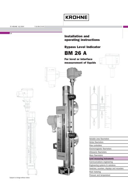
Installation and<br />
operating instructions<br />
Bypass Level Indicator<br />
<strong>BM</strong> <strong>26</strong> A<br />
For level or interface<br />
measurement of liquids<br />
Subject to change without notice.<br />
Variable area flowmeters<br />
Vortex flowmeters<br />
Flow controllers<br />
Electromagnetic flowmeters<br />
Ultrasonic flowmeters<br />
Mass flowmeters<br />
Level measuring instruments<br />
Communications engineering<br />
Engineering systems & solutions<br />
Switches, counters, displays and recorders<br />
Heat metering<br />
Pressure and temperature
Contents<br />
General advice on safety.................................................................................................................4<br />
Handling ...........................................................................................................................................4<br />
Product liability and warranty.........................................................................................................4<br />
Items supplied..................................................................................................................................4<br />
Description: <strong>BM</strong> <strong>26</strong> A bypass level indicator with magnetic flaps or bar scale .........................5<br />
Standards / Approvals.....................................................................................................................5<br />
Official approvals and certificates .................................................................................................6<br />
Principal gauge components..........................................................................................................6<br />
1 Installation.............................................................................................................................7<br />
1.1 Packing and storage...............................................................................................................7<br />
1.2 Mechanical installation requirements......................................................................................8<br />
1.3 Mounting on the tank ..............................................................................................................9<br />
1.4 Start-up procedure................................................................................................................10<br />
1.5 True level indication..............................................................................................................11<br />
1.5.1 Level measurement using the local indicator and scale .......................................................11<br />
1.5.2 Correcting the scale position to accurately read true liquid level*.........................................12<br />
1.5.3 Functional check of local level display..................................................................................14<br />
1.6 <strong>BM</strong> <strong>26</strong> A construction details ................................................................................................14<br />
2 Level transducer.................................................................................................................17<br />
2.1 Transmitters..........................................................................................................................18<br />
2.1.1 Transmitter versions for the <strong>BM</strong> <strong>26</strong> A ...................................................................................18<br />
2.1.2 Electrical connections...........................................................................................................18<br />
3 Limit switches / contacts ...................................................................................................19<br />
3.1 Designation code for defining limit switch versions...............................................................19<br />
3.2 Limit switch options for the <strong>BM</strong> <strong>26</strong> A (non-Ex)......................................................................19<br />
3.3 Limit switch options for the <strong>BM</strong> <strong>26</strong> A (Ex) .............................................................................20<br />
3.4 How to use a limit switch ......................................................................................................20<br />
3.4.1 Operating principle ...............................................................................................................20<br />
3.4.2 Installation ............................................................................................................................20<br />
3.4.3 Overall dimensions of limit switches mounted on measuring tube........................................22<br />
3.4.4 Limit switch dimensions (without bracket and clamp) ...........................................................23<br />
3.4.5 Electrical connections...........................................................................................................24<br />
3.4.6 Important notes: MS 20 load protection................................................................................25<br />
3.5 Fine adjustments to the limit switch trigger point ..................................................................25<br />
3.5.1 Fine adjustments to the limit switch trigger point ..................................................................<strong>26</strong><br />
3.5.2 Switching point diagram and offset values for limit switches ................................................<strong>26</strong><br />
4 Special versions .................................................................................................................27<br />
4.1 Low-temperature versions AG-TR-IC/TR .............................................................................27<br />
4.2 High-temperature versions HR-IC/HR ..................................................................................27<br />
4.3 Heating system for measuring tube <strong>BM</strong> <strong>26</strong> A/B....................................................................28<br />
4.4 Liquid/liquid interface measurement <strong>BM</strong> <strong>26</strong> A/TS.................................................................28<br />
2 Installation and operating instructions <strong>BM</strong> <strong>26</strong> A
5 Floats................................................................................................................................... 29<br />
5.1 Float types............................................................................................................................ 29<br />
5.1.1 Float dimensioned diagrams ................................................................................................ 29<br />
5.2 Changing the process conditions ......................................................................................... 30<br />
5.3 Floats application limits ........................................................................................................ 32<br />
5.3.1 Density and temperature limits............................................................................................. 32<br />
5.3.2 Operating pressure limits ..................................................................................................... 32<br />
6 Maintenance ....................................................................................................................... 33<br />
7 Ordering spare parts.......................................................................................................... 33<br />
8 Technical data .................................................................................................................... 34<br />
8.1 <strong>BM</strong> <strong>26</strong> A ............................................................................................................................... 34<br />
8.2 Level transmitter modules .................................................................................................... 35<br />
8.3 Limit switches....................................................................................................................... 36<br />
8.4 Guide tube assembly materials ............................................................................................ 37<br />
8.4.1 <strong>BM</strong> <strong>26</strong> A Bypass Indicator: compliance with Pressure Equipment Directive 97 /23 /EC<br />
constraints............................................................................................................................ 37<br />
8.4.2 Maximum operating conditions for <strong>BM</strong> <strong>26</strong> A with 316 Ti steel measuring tube .................... 38<br />
8.4.3 Flange categories for operating conditions in a 316 Ti steel measuring tube....................... 38<br />
8.4.4 Maximum operating conditions for <strong>BM</strong> <strong>26</strong> A with 316 L steel measuring tube ..................... 39<br />
8.4.5 Flange categories for operating conditions in a 316 L steel measuring tube........................ 39<br />
8.5 <strong>BM</strong> <strong>26</strong> A weights and dimensions ........................................................................................ 40<br />
8.5.1 Weights ................................................................................................................................ 40<br />
8.5.2 Indicator dimensions ............................................................................................................40<br />
8.5.3 Overall dimensions of measuring tube classes (with loose or welding neck flanges)........... 40<br />
8.5.4 Distance of welding neck flange raised facing from measuring tube axis............................. 43<br />
9 Measuring principle ........................................................................................................... 44<br />
Appendices .................................................................................................................................... 45<br />
Appendix A: Declaration of conformity: CE................................................................................ 45<br />
Appendix B: Declaration of conformity: Pressure Equipment Directive 97/23/EC .................. 46<br />
If you need to return a device for testing or repair to KROHNE ................................................ 47<br />
Installation and operating instructions <strong>BM</strong> <strong>26</strong> A 3
General advice on safety<br />
Handling<br />
This manual gives a complete set of instructions for the installation, operation and<br />
maintenance of the ATEX version of the <strong>BM</strong> <strong>26</strong> A Bypass Level Indicator.<br />
Special regulations are applicable to the use of equipment in hazardous locations,<br />
and these are described in this booklet. Data is supplied on explosion protection.<br />
The instrument must be installed and used by suitably qualified personnel.<br />
Our conformity declaration is limited to the parts of the level indicator that are under<br />
pressure, excluding parts that may be dismantled (e.g. valves).<br />
The standard design calculation does not take into account the theoretical<br />
coefficient of corrosion. The product circulating in the vessel must not have<br />
properties that give rise to surface erosion.<br />
Events that are not taken into account in the calculations include: exceptional risks<br />
such as earthquakes, bad weather, acts of destruction (such as sabotage,<br />
terrorism, vandalism, etc.) and fire.<br />
This instrument is designed to function at near constant pressure conditions.<br />
Special measures must be taken when using titanium floats in order to avoid<br />
friction between the titanium and stainless steel causing sparks in an inflammable<br />
gaseous environment.<br />
The device normally weighs from 14.5 kg or 32 lb to 40kg or 88 lb. Carry the device<br />
using at least two people, lifting it by the process connections. Lifting gear may also<br />
be used but no attempt should be made to lift the device by the measuring scale,<br />
level transducer or other attached equipment.<br />
Product liability and warranty<br />
The <strong>BM</strong> <strong>26</strong> A bypass level indicator is designed exclusively for liquid-level, liquid/liquid interface or<br />
volume measurement, depending on the scale and float selected by the customer.<br />
Special codes and regulations apply to its use in hazardous areas.<br />
Responsibility as to suitability and intended use of this bypass level indicator rests solely with the<br />
operator.<br />
Improper installation and operation of these bypass level indicators may lead to loss of warranty.<br />
In addition, the “General conditions of sale” forming the basis of the purchase contract are<br />
applicable.<br />
If the bypass level indicator needs to be returned to KROHNE, please read and follow the<br />
instructions given at the end of this manual.<br />
Items supplied<br />
• <strong>BM</strong> <strong>26</strong> A bypass level indicator option: with or without current output or limit switches<br />
• These installation and operating instructions<br />
• Approval documents / certificates of conformity (for hazardous duty only)<br />
Supplied without mounting accessories (stud bolts, flange gaskets and wiring to be provided by<br />
customer).<br />
Special certificates (Optional: supplied on customer demand only)<br />
• Test certificate to EN 10204: pressure test, dye penetration test, radiographic test, leak-tightness<br />
test, ultrasonic test, helium leak test, surface cleanness and material<br />
• Ultrasonic cleaning to factory specification.<br />
4 Installation and operating instructions <strong>BM</strong> <strong>26</strong> A
Description: <strong>BM</strong> <strong>26</strong> A bypass level indicator with magnetic flaps or bar scale<br />
The <strong>BM</strong> <strong>26</strong> A bypass level indicator is used for measuring level, interface or volume in open or<br />
pressurized tanks. It is mounted adjacent to the tank and uses the principle of communicating<br />
vessels – the liquid level in the measuring tube corresponds to the liquid level in the tank. Due to its<br />
design, the unit is suitable for use in connection with corrosive, toxic or flammable substances and in<br />
severe service conditions.<br />
The local indicator consists of:<br />
• A bar indicator (follower magnet) in a Pyrex glass tube as standard<br />
• or a flap indicator (yellow/black magnetic flaps) in a Pyrex glass tube.<br />
No power is required for local liquid-level indication.<br />
Optionally, the unit can be equipped or retrofitted with an electrical analogue level transducer<br />
system and/or limit switches.<br />
Use in hazardous areas<br />
The <strong>BM</strong> <strong>26</strong> A bypass level indicator is approved for use in explosive atmospheres when equipped<br />
with the appropriate options. It is imperative that the approval certificate details and boundary<br />
conditions are observed.<br />
Standards / Approvals<br />
In compliance with European Directive 94/9/EC (ATEX 100a), the bypass level<br />
indicators described in these instructions conform to European Standards EN 50014,<br />
EN 50020, EN 50018, EN 13463-1 and EN 50284 and are certified for use in<br />
hazardous locations by the INERIS certification agency under INERIS 02ATEX0088X<br />
when equipped with the appropriate options.<br />
The details given in this approval certificate together with its boundary conditions must be observed.<br />
This instrument also conforms to the European Union Pressure Equipment Directive 97/23/EC.<br />
Ex Safety Instructions<br />
ATEX-certified <strong>BM</strong> <strong>26</strong> A level indicators can be used in explosive atmospheres of all flammable<br />
substances in Gas Group IIC (with the exception of cases given in these instructions) and<br />
applications requiring Category 1 / 2 G and 1 G equipment.<br />
Ex Equipment Category Definitions<br />
Category 1 / 2 G – instruments<br />
(for applications where the Exd-rated explosion-proof box is used)<br />
The signal converter for current output and limit switch options are located in hazardous areas<br />
requiring instruments qualified as being category 2. The process connection and tank wall form an<br />
interface between zones for category 1 and 2 equipment. The indicator measuring elements (float<br />
and measuring tube) are qualified as being category 1. The G rating states that the instrument is<br />
qualified for gas environments.<br />
Category 1 G - instruments<br />
The signal converter for current output, limit switch options and measuring components are located<br />
in hazardous areas requiring instruments qualified as being category 1.<br />
Installation and operating instructions <strong>BM</strong> <strong>26</strong> A 5
Official approvals and certificates<br />
Application Approved by Instrument version Certification mark<br />
ATEX certification INERIS <strong>BM</strong> <strong>26</strong> A Certificate no.<br />
INERIS 02ATEX0088X*<br />
*This EC-type Examination Certificate is available on KROHNE’s download centre webpage on<br />
http://www.krohne.com.<br />
Principal gauge components<br />
1 Level<br />
transducer<br />
(cable entry<br />
fitting not<br />
supplied)<br />
2 Process<br />
connections<br />
3 Measuring tube<br />
(bypass<br />
chamber)<br />
containing float<br />
loaded with<br />
magnets<br />
4 MS 15 /EXD<br />
limit switch<br />
(cable entry<br />
fitting not<br />
supplied)<br />
5 MS 15 /STD or<br />
/EXI limit switch<br />
6 MS 20 /STD or<br />
/EXI limit switch<br />
(shown<br />
separate from<br />
assembly, may<br />
replace or be<br />
used with items<br />
4 and 5)<br />
7 Scale clamped<br />
adjacent to<br />
measuring tube<br />
integrating a<br />
Pyrex tube with<br />
float-following<br />
indicator bar.<br />
6 Installation and operating instructions <strong>BM</strong> <strong>26</strong> A
1 Installation<br />
1.1 Packing and storage<br />
Floats packed separately<br />
1 To install, remove the bottom flange and insert the float – the right way up – into the guide<br />
chamber.<br />
2 Align gaskets.<br />
3 Tighten nuts using the correct torque with regards to the strength of bolts specified for the<br />
vessel pressure rating, connecting flange and material.<br />
Make sure that the guide tube is free of foreign bodies<br />
(dirt, loose objects, etc.).<br />
Floats held in position during transit by a plastic locking clip<br />
This should be removed from the guide tube before installation through the bottom connection<br />
flange. Follow the procedure below:<br />
Step 1<br />
Check measuring tube for a red sticker next to the bottom process connection.<br />
ATTENTION!<br />
Retirer la tige de sécurité<br />
maintenant le flotteur<br />
ATTENTION !<br />
Take away transport safety<br />
device for float<br />
ACHTUNG !<br />
Transportsicherung für<br />
Schwimmer entfernen<br />
Installation and operating instructions <strong>BM</strong> <strong>26</strong> A 7
Step 2<br />
Undo adhesive tape around<br />
bottom process connection<br />
Step 3 Remove process connection plastic<br />
protective cover<br />
Step 4 Locate clip Step 5 Remove clip with a pair of pliers<br />
1.2 Mechanical installation requirements<br />
Ensure that the requirements given below have been followed:<br />
• The effective pressure of the installation (the maximum permitted by the pressure limiting valve)<br />
must never be greater than the maximum permitted pressure, P s , marked on the instrument<br />
nameplate. The test pressure, P t , is given on the order documents and <strong>BM</strong> <strong>26</strong> A nameplate.<br />
• The user must be sure that materials in contact (guide tube, float, gaskets, etc) with the fluid<br />
used are compatible with the fluid and conform to ageing characteristics of the fluid used and the<br />
measurement environment. These have either been recommended in the instructions or form the<br />
subject of a particular specification in the contract.<br />
• The external pressure (P ext ) must be equal to atmospheric pressure (P atmos ).<br />
8 Installation and operating instructions <strong>BM</strong> <strong>26</strong> A
1 Tank<br />
2 Liquid product<br />
=<br />
3 <strong>BM</strong> <strong>26</strong>A level-liquid indicator<br />
(measuring tube):<br />
Vertical installation only!!<br />
1.3 Mounting on the tank<br />
• The <strong>BM</strong> <strong>26</strong> A bypass level indicator must be installed vertically on the tank<br />
• When installing the <strong>BM</strong> <strong>26</strong> A bypass level indicator with or without the electrical level transducer<br />
system, make sure that any magnetic fields generated by other equipment will not affect<br />
measurements.<br />
• Select bolts and gaskets (supplied by customer) that correspond to the pressure rating of the<br />
connecting flange and the operating pressure.<br />
• The process connections (flanges) must fit perfectly, i.e. they must be centred, parallel and<br />
bolted in a professional way, in order to avoid unnecessary mechanical stress on the installation.<br />
• The tank must be free of contaminants. It is recommended to install shut-off elements, e.g.<br />
cocks, valves, etc., between the tank and bypass level indicator to allow the bypass level<br />
indicator to be cleaned independently of the tank. The drain plug in the bottom flange should<br />
also be replaced by a drainage cock with discharge line.<br />
1 Shut-off valve (top and bottom)<br />
2 Drainage valve with discharge tube.<br />
3 Vent plug<br />
Installation and operating instructions <strong>BM</strong> <strong>26</strong> A 9
• Additional anchoring points between the <strong>BM</strong> <strong>26</strong> A and the tank are recommended for very high<br />
installations (above 6 metres length for stainless steel). The standard anchor is a set of collars<br />
welded to a plate. This is available on demand from KROHNE. See figure below for side and<br />
plan view and dimensions in millimetres (inches).<br />
1.4 Start-up procedure<br />
Take the necessary safety precautions when working with<br />
pressurized tanks.<br />
Step Action<br />
1 Close drainage plugs and/or drainage cock .<br />
2 Open shutoff elements at lower and upper connecting flange.<br />
3 Adjust the position of the local measuring scale so that scale<br />
level corresponds exactly to true level, see section 1.5.<br />
Other important notes<br />
• The user must take the necessary steps to protect the installed instrument from<br />
shock waves (waterhammer). A pressure limiting valve must equally protect the<br />
rest of the installation.<br />
• The instrument must regularly undergo servicing to conform to the rules and<br />
regulations applicable to the site that it is installed on.<br />
• High Temperature versions - precautions must be taken to avoid burns to<br />
operators.<br />
10 Installation and operating instructions <strong>BM</strong> <strong>26</strong> A
1.5 True level indication<br />
1.5.1 Level measurement using the local indicator and scale<br />
The float is equipped with a ring system of permanent magnets for transmission of liquid level to the<br />
indicator. The indicator is linked magnetically to the magnet system in the float.<br />
For design reasons, the minimum level in the measuring tube is given by the lower lateral flange<br />
connection axis i.e. liquid level zero is the centreline of the lower connecting flange. As can be seen<br />
in the diagram of the float and indicator on the next page, the indicator follows the float below the<br />
liquid level.<br />
There is a difference between true liquid level and the indicator position because:<br />
• the float is immersed to a certain depth depending on the product density and float type,<br />
• the float magnets are positioned below the float centreline in order for the float to have good<br />
stability.<br />
The scale is delivered correctly set up for measuring the product specified in the order. The red<br />
reference mark at the top of the measuring tube (item 1 in the diagram below) shows where the top<br />
of the scale must be clamped for the indicator to give an accurate reading of liquid level. No further<br />
adjustment is necessary when the gauge is commissioned.<br />
If there is a large change in product density, a product other than the one<br />
specified in the order is measured or a different float is installed, the scale on the<br />
<strong>BM</strong> <strong>26</strong> A may require adjusting to give an accurate reading. Contact KROHNE for<br />
assistance (see also section 1.5.2 to correct the scale’s position).<br />
1 Reference mark : the top of the upper red<br />
KROHNE plate must touch the bottom point<br />
of the triangle<br />
2 Scale<br />
3 Measuring tube (containing float)<br />
4 Top clamping collar ( scale-measuring tube)<br />
Installation and operating instructions <strong>BM</strong> <strong>26</strong> A 11
1.5.2 Correcting the scale position to accurately read true liquid level*<br />
The scale can be corrected by the customer using the following procedure:<br />
Step Action<br />
1 Find the float immersion depth “c” (supplied by KROHNE, refer also to section 5).<br />
2 Subtract the dimension “a”, float base to magnet centreline (given on the float dimensioned<br />
drawing in Section 5.1.1), from “c” to get the dimension “b”, scale correction factor.<br />
Item<br />
Description<br />
b c – a (difference between liquid level<br />
and indicator position due to product<br />
density)<br />
c float immersion depth (a function of<br />
product density), see section 5.2.<br />
a distance from centreline of magnet<br />
system to the float base, see<br />
dimensioned float drawings in<br />
section 5.1.1.<br />
1 Float<br />
2 Follower magnet of indicator (or limit<br />
switch)<br />
3 Position of magnets mounted in the<br />
float<br />
3 Loosen the two clamp collars holding the measuring scale onto the measuring tube using a<br />
screwdriver or 8 mm wrench.<br />
4 Bring the zero point (top of the lower red KROHNE plate) on the scale into line with the<br />
centreline of the bottom lateral process connection.<br />
Step 3: Undo top collar<br />
1 Measuring scale<br />
2 Measuring tube<br />
3 Top measuring scale collar<br />
*This information also applies to the initial setting up of limit switches – however, the fitter should<br />
also remember to take into account the limit switches offset trigger point (see section 3.6).<br />
12 Installation and operating instructions <strong>BM</strong> <strong>26</strong> A
Step 3: Undo bottom collar<br />
Step 4: Zero the scale (default)<br />
1 Measuring scale<br />
2 Bottom of scale ( item 1) indicated<br />
by top of red KROHNE plate.<br />
Default position is on the same level<br />
as item 3.<br />
3 Centreline of bottom lateral process<br />
connection.<br />
4 Bottom measuring scale clamp<br />
5 Move the measuring scale down the measuring tube to set to by “b” mm.<br />
1 Centreline of bottom lateral process<br />
connection.<br />
2 Bottom of scale ( item 1) indicated<br />
by top of red KROHNE plate.<br />
3 Position of float (dashed lines)<br />
when measuring tube filled up to<br />
the centre line of bottom lateral<br />
process connection.<br />
b<br />
Move scale down measuring tube<br />
by “b” mm. The bottom of the scale<br />
will then be at the same level as the<br />
magnets in the float<br />
6 Retighten the two collars holding the measuring scale onto the measuring tube.<br />
1 Measuring scale collar screw<br />
Installation and operating instructions <strong>BM</strong> <strong>26</strong> A 13
1.5.3 Functional check of local level display<br />
• The lower end of the indicator tube extends beyond the zero point of the scale. When magnetic<br />
bonds between the indicator system (9*) and the float magnet system are broken, the indicator<br />
(float follower bar) will drop down and disappear behind the red cover (12*) on the front scale.<br />
• Use a bar magnet to retrieve the indicator until it is attracted to the float. When the indicator is<br />
visible and the two sets of magnets are drawn to each other, the indicated value will be correct.<br />
*See diagram below.<br />
1.6 <strong>BM</strong> <strong>26</strong> A construction details<br />
The diagram below shows a standard <strong>BM</strong> <strong>26</strong> A/C/RR without level transducer and switch options<br />
1 Vent plug<br />
2 Measuring tube<br />
3 Red triangle reference mark giving<br />
factory-calculated zero position of<br />
measuring scale<br />
4 Glass tube for indicator<br />
5 Scale<br />
6 Float (magnets mounted in lower half)<br />
7 Liquid level<br />
8 Mid-point of indicator<br />
9 Indicator (standard follower bar)**<br />
10 Zero point of measurement<br />
(centreline of lower connecting flange)<br />
11 Scale zero<br />
12 Stop (red KROHNE plate)<br />
13 Instrument nameplate<br />
** optional flap indicator available (see section 9)<br />
Details:<br />
Item 12 – The bottom Stop / Red KROHNE plate has a label listing the product and the operating<br />
conditions. For example:<br />
Working pressure :<br />
Working temperature :<br />
Density :<br />
Fluid :<br />
6 bar g<br />
25 C<br />
0.778 s g.<br />
cyclohexane<br />
14 Installation and operating instructions <strong>BM</strong> <strong>26</strong> A
Item 13A – <strong>BM</strong> <strong>26</strong> A STANDARD nameplate<br />
Item 13B – <strong>BM</strong> <strong>26</strong> A ATEX nameplate<br />
* See <strong>BM</strong> <strong>26</strong> A Data Sheet for a list of standard options and designation codes<br />
** Type code is defined as:<br />
Product code/Process connections/Material code/Design/Level transducer/Contact/Approval<br />
Installation and operating instructions <strong>BM</strong> <strong>26</strong> A 15
Type code element Code Code definition<br />
Product code <strong>BM</strong> <strong>26</strong> A Bypass Level Indicator (A model)<br />
Process connections C<br />
D<br />
E<br />
F<br />
Two lateral connections<br />
Two axial connections<br />
One top lateral entry and one bottom axial exit<br />
One bottom lateral entry and one top axial exit<br />
Construction material code RR Stainless steel<br />
Design<br />
No info<br />
B<br />
AG<br />
IC/TR<br />
IC/HR<br />
Level transducer<br />
Contact<br />
Approval<br />
No info<br />
ER<br />
No info<br />
K<br />
No info<br />
EXI<br />
EXD<br />
Standard design<br />
Heater<br />
Anti-freeze version<br />
With low temperature insulation<br />
With high temperature insulation<br />
Without level transducer<br />
With level transducer<br />
Without limit switches<br />
With limit switches<br />
Standard, no approval<br />
For EEx – intrinsically safe applications<br />
For EEx – flameproof applications<br />
16 Installation and operating instructions <strong>BM</strong> <strong>26</strong> A
2 Level transducer<br />
In addition to the local scale indicator, the <strong>BM</strong> <strong>26</strong> A can be fitted with a level transducer that<br />
transmits a magnetically-actuated 4 … 20 mA analogue current output for monitoring level outside a<br />
hazardous zone.<br />
This type of indication uses a stainless steel tube containing a resistive reed contact chain that is<br />
clamped adjacent to the measuring tube. The position of the float magnet in the measuring tube<br />
determines the output. This output is calibrated at the factory and does not require any further<br />
adjustment when the <strong>BM</strong> <strong>26</strong> A is commissioned.<br />
The transducer reading is converted into a current output of 4 … 20 mA by the transmitter that is<br />
potted into the transducer housing. The transmitter module used is detailed in the following subsection<br />
(detailed technical data is given in section 8.2). The intrinsically safe transmitter may be<br />
used with or without a galvanically-isolated 4 … 20 mA output for the <strong>BM</strong> <strong>26</strong> A EEx ia version.<br />
<strong>BM</strong> <strong>26</strong> A Std/ EExi/EExd with level transducer (aluminium transmitter housing)<br />
1 Cable entry.<br />
Only Exd-certified<br />
components and cable entry<br />
fittings to be connected!<br />
With M20 x 1.5 thread.<br />
Optional: M25 x 1.5<br />
NPT ¾<br />
2 Level transducer housing<br />
3 Stainless steel tube-encased<br />
reed chain<br />
4 <strong>BM</strong> <strong>26</strong> A measuring tube and<br />
scale with magnetic following<br />
level-indicator<br />
5 PE Ground terminals.<br />
Both terminals must be<br />
connected to Ground!<br />
Dimensions in mm (inches)<br />
Installation and operating instructions <strong>BM</strong> <strong>26</strong> A 17
2.1 Transmitters<br />
The level transducer is defined by the type of communication used (ER – electronic remote),<br />
housing protection, housing material (AL – aluminium) and transmitter module.<br />
2.1.1 Transmitter versions for the <strong>BM</strong> <strong>26</strong> A<br />
Version designation Housing protection Transmitter module<br />
ER/STD/AL/D<br />
Without (non-Ex)<br />
D Prelevel<br />
ER/EXI/AL/D<br />
EXI (EExia)<br />
ER/EXD/AL/D<br />
EXD (EExd)<br />
2.1.2 Electrical connections<br />
Do not remove the transducer cover until the power supply<br />
has been disconnected<br />
PRelevel (top view)<br />
18 Installation and operating instructions <strong>BM</strong> <strong>26</strong> A
3 Limit switches / contacts<br />
To signal specific liquid levels, the <strong>BM</strong> <strong>26</strong> A bypass level indicator can be equipped with 13 different<br />
types of limit switch that are clamped to the measuring tube and are adjustable over the whole<br />
measuring range. They are actuated by a magnet incorporated into the float. The operating<br />
conditions define which limit switches may be used. Refer to section 8.3 for detailed technical data<br />
on each type of limit switch.<br />
The limit switches are delivered separate from the <strong>BM</strong> <strong>26</strong> A gauge and have to be mounted on site.<br />
See sections 3.4 to 3.6 for installation instructions.<br />
3.1 Designation code for defining limit switch versions<br />
Housing<br />
protection<br />
STD (Without)<br />
EXI (EExia)<br />
EXD (EExd)<br />
Cut-out<br />
power<br />
LC (Low power<br />
cut-out)<br />
HC (High power<br />
cut-out)<br />
Housing<br />
material<br />
NAMUR<br />
conformity<br />
Process<br />
temperature<br />
applications<br />
BT (Low<br />
PC (Polycarbonate /<br />
Standard)<br />
NN (Non-<br />
NAMUR) temperature)<br />
AL (Aluminium) NO (NAMUR) HT (High<br />
temperature)<br />
3.2 Limit switch options for the <strong>BM</strong> <strong>26</strong> A (non-Ex)<br />
Designation<br />
MS20/STD/L<br />
C/PC/NN/BT<br />
MS15/STD/L<br />
C/PC/NO/BT<br />
MS15/STD/L<br />
C/AL/NN/HT<br />
MS15/STD/L<br />
C/AL/NO/HT<br />
MS15/STD/H<br />
C/PC/NN/BT<br />
MS15/STD/H<br />
C/AL/NN/HT<br />
Housing<br />
protection<br />
Housing<br />
material<br />
Without PC 20 VA<br />
1.5 A<br />
Power cut-out Process temperature Ambient<br />
temperature<br />
/ °C<br />
Ambient<br />
temperature<br />
/ °F<br />
3.3 Limit switch options for the <strong>BM</strong> <strong>26</strong> A (Ex)<br />
Designation<br />
MS20/EXI/LC/<br />
PC/NN/BT<br />
MS15/EXI/LC/<br />
PC/NO/BT<br />
MS15/EXI/<br />
LC/AL/NN/HT<br />
MS15/EXI/<br />
LC/AL/NO/HT<br />
MS15/EXD/LC/A<br />
L/NN/HT<br />
MS15/EXD/LC/A<br />
L/NO/HT<br />
MS15/EXD/HC/A<br />
L/NN/HT<br />
Housing<br />
protection<br />
Housing<br />
material<br />
Power cut-out<br />
Process<br />
temperature<br />
Ambient<br />
temperature<br />
EXI* PC 1.5 A* ** ** U i<br />
I i<br />
C i<br />
EXI* PC NAMUR ** ** U i<br />
I i<br />
C i<br />
EXI* ALU 1.5 A* ** ** U i<br />
I i<br />
C i<br />
EXI* ALU NAMUR ** ** U i<br />
I i<br />
C i<br />
EXD ALU 20 VA<br />
1.5 A<br />
250 VAC<br />
Power supply<br />
characteristics<br />
L i<br />
L i<br />
L i<br />
L i<br />
****<br />
100mA<br />
0<br />
0<br />
24 V<br />
***<br />
0<br />
0<br />
****<br />
500mA<br />
0<br />
24V<br />
***<br />
0<br />
0<br />
** ** n/a<br />
EXD ALU NAMUR ** ** n/a<br />
EXD ALU Max.: 100 VA<br />
Min.: 3 VA<br />
1.5 A<br />
250 VAC<br />
** ** n/a<br />
* To be connected to a certified intrinsically-safe power supply only.<br />
** Dependant on ATEX temperature class. Refer to section 8.1 for further information.<br />
*** The current value is not imposed, however the power supply must be intrinsically-safe.<br />
**** The voltage value is not defined, however the power supply must be intrinsically-safe.<br />
3.4 How to use a limit switch<br />
3.4.1 Operating principle<br />
The MS 15/STD, MS 15/EXI, MS 15/EXD, MS 20/STD and MS 20/EXI limit switches consist of a<br />
reed contact that is actuated directly by the magnet system in the float. Due to their bi-stable<br />
switching characteristic, the switching state is maintained until the float magnet system again<br />
activates the limit switch in the opposite direction. Line-side connection of a suitable isolation<br />
switching amplifier is recommended.<br />
3.4.2 Installation<br />
1 Attach the switch to the measuring tube at the desired level using the metal collar supplied.<br />
2 Adjust the switch level to take into account the difference between indicated level and true level<br />
(see section 1.5).<br />
3 Adjust the switch level to take into account limit switch trigger point offset (see section 3.6).<br />
Note: Due to its bi-stable characteristic, the switch can be operated in open-circuit or closedcircuit<br />
mode (see section 3.4.5 Electrical connections below), when appropriately<br />
connected.<br />
20 Installation and operating instructions <strong>BM</strong> <strong>26</strong> A
Clamping in position on measuring tube<br />
MS 15 /STD or /EXI<br />
1 Limit switch clamp<br />
2 Limit switch bracket<br />
3 Measuring scale<br />
clamp<br />
4 Measuring tube<br />
5 2 x M4 screws (for<br />
bracket)<br />
6 Switching point<br />
centerline<br />
Fine adjustment:<br />
See procedure,<br />
section 3.5<br />
7 MS 15 /STD or /EXI<br />
limit switch cover<br />
MS 15 /EXD<br />
1 1 x locking screws M6<br />
-use Ø3 mm Allen key<br />
2 Limit switch<br />
bracket<br />
3 Limit switch clamp<br />
4 Measuring tube<br />
5 Measuring scale<br />
clamp<br />
6 Switching point<br />
centerline<br />
Fine adjustment:<br />
See procedure,<br />
section 3.5<br />
7 Cover lock:<br />
M3 screw -<br />
use Ø2 mm Allen key<br />
8 MS15 EXD<br />
limit switch cover<br />
9 Cable fitting (not<br />
supplied by KROHNE)<br />
Installation and operating instructions <strong>BM</strong> <strong>26</strong> A 21
MS 20 /STD or /EXI<br />
1 Limit switch clamp (switch<br />
has an integral bracket)<br />
2 Measuring scale clamp<br />
3 Measuring tube<br />
4 Switching point centerline<br />
Fine adjustment:<br />
See procedure, section 3.5<br />
5 MS20 /STD or /EXI<br />
limit switch cover<br />
3.4.3 Overall dimensions of limit switches mounted on measuring tube<br />
MS 15/STD and MS 15/EXI<br />
MS 15/EXD<br />
* Item 1: limit switch collar scew<br />
MS 20/STD and MS 20/EXI<br />
1 Metal clamping collar screw<br />
2 MS 20 limit switch<br />
3 Measuring tube<br />
Dimensions in mm (inches)<br />
22 Installation and operating instructions <strong>BM</strong> <strong>26</strong> A
3.4.4 Limit switch dimensions (without bracket and clamp)<br />
MS 15/STD and /EXI with PG13.5 fitting<br />
Side view<br />
MS 15/EXD/**/AL without cable fitting (supplied<br />
by customer)<br />
Side view<br />
Top view<br />
MS 20/STD and /EXI with PG9 fitting and integrated bracket<br />
Side view<br />
Dimensions in mm (inches)<br />
Installation and operating instructions <strong>BM</strong> <strong>26</strong> A 23
3.4.5 Electrical connections<br />
Unscrew the housing cover at the rear. For technical data, see Section 8.3. Use connections that<br />
are certified for Exd applications for EXD casings. Wire as shown below:<br />
Do not remove the limit switch cover until the power supply has been<br />
disconnected<br />
MS 15/STD or /EXI terminals<br />
MS 15/EXD terminals<br />
1 Terminals<br />
2 Cable entry fitting PG13.5<br />
1 Terminals<br />
2 Hole with M20 x 1.5 thread. Cable fitting<br />
supplied by customer<br />
MS 15/STD/NAMUR or<br />
MS 15/EXI/NAMUR terminals<br />
1 Terminals<br />
2 Cable entry fitting<br />
PG 13.5<br />
MS 20/STD and /EXI terminals<br />
1 Cable entry fitting PG9<br />
2 Terminal block<br />
3 Blue wire (terminal 1)<br />
4 Black wire (terminal 3)<br />
5 Brown wire (terminal 2)<br />
24 Installation and operating instructions <strong>BM</strong> <strong>26</strong> A
3.4.6 Important notes: MS 20 load protection<br />
Inductive load protection<br />
If the MS 20 switch is connected to an inductive load, it may be damaged<br />
beyond repair. A protective circuit with an RC-element or a freewheeling diode<br />
should be included to avoid this.<br />
Capacitive load protection<br />
If connected to a capacitive load, a protective resistor should be connected in<br />
series to limit the peak current.<br />
3.5 Fine adjustments to the limit switch trigger point<br />
Due to the way the reed switch switches from one state to another and the geometry of magnets<br />
integrated into the float, different switching points are obtained when the float moves up or down.<br />
This must be taken into account when positioning the limit switch.<br />
The assembler must equally remember that as with the local display, limit switch position must take<br />
into account the fact that indicated level is lower than true level.<br />
By default, indicated level is lower than true level by “b” mm. This should be adjusted during<br />
commissioning (see section 1.5.2). When the float moves up, the switch is triggered with the float<br />
offset by “d” mm. When the float moves down, the switch is triggered with the float offset by “e” mm.<br />
Hysteresis: see Section 8.3.<br />
Installation and operating instructions <strong>BM</strong> <strong>26</strong> A 25
3.5.1 Fine adjustments to the limit switch trigger point<br />
Step Action<br />
1 Choose the true level at which the limit switch should signal “limit reached“.<br />
2 Adjust the switch position using the procedure in Section 1.5.1 to take into account the<br />
difference between true liquid level and indicated level (magnet position). Move switch down<br />
measuring tube by “b” mm.<br />
3 Refer to the table in section 3.5.2: “Switching point offsets“. Find the limit switch offset based<br />
on the limit switch type and the direction in which the float is moving for the switch to be<br />
triggered. Example: if the switch has to trigger when the float moves upwards then a MS<br />
15/STD switch needs to be moved down the measuring tube by 5 mm or 0.2 ”.<br />
4 Loosen the collar holding the limit switch onto the measuring tube.<br />
5 Now re-position again to take into account the switch trigger points -Move the switch up or<br />
down the measuring tube by the amount required for the offset as indicated in the table and<br />
drawing in section 3.5.2.<br />
6 Retighten the collar holding the limit switch onto the indicator tube.<br />
3.5.2 Switching point diagram and offset values for limit switches<br />
Item Description<br />
0 zero scale mark<br />
b difference between liquid level and scale reading due to product density<br />
L level indication (limit value) on the scale<br />
d Trigger point offset of limit switch when the float goes up (distance between contact<br />
centreline and level indication or limit value - see table below)<br />
e Trigger point offset of limit switch when the float goes down (distance between contact<br />
centreline and level indication or limit value)<br />
Switching point offsets<br />
Offset due to direction of<br />
float displacement<br />
Limit switch d (Up) e (Down)<br />
mm inch mm inch<br />
MS 15/STD<br />
MS 15/EXI<br />
– 5 – 0.2 – 5 – 0.2<br />
MS 15/EXD<br />
MS 20/STD<br />
MS 20/EXI<br />
– 5 – 0.2 – 5 – 0.2<br />
Dimensions in mm (inches)<br />
<strong>26</strong> Installation and operating instructions <strong>BM</strong> <strong>26</strong> A
4 Special versions<br />
4.1 Low-temperature versions AG-TR-IC/TR<br />
Version <strong>BM</strong> <strong>26</strong> A/AG: to -40°C or -40°F<br />
Version <strong>BM</strong> <strong>26</strong> A/TR: to -200°C or -330°F<br />
Version <strong>BM</strong> <strong>26</strong> A/IC/TR: to -200°C or -330°F<br />
All components are made of solid CrNi steel grade 316 Ti (equivalent to 1.4571) or 316 L (equivalent<br />
to 1.4404). The measuring tube in the <strong>BM</strong> <strong>26</strong> A/IC/TR has glass wool insulation and aluminium<br />
cladding. The float magnets are made of a special material.<br />
The scale indication is magnified by plexitherm glass for easier reading. The ambient temperature<br />
and product temperature will have been specified by the customer to ensure insulation is<br />
appropriate.The socket length to the connecting flange will have been specified by the customer if<br />
insulation is supplied by the customer.<br />
Version AG Version TR Version IC/TR<br />
1 Plexitherm glass 1 Measuring tube 1 Measuring tube<br />
2 Indicator scale 2 Indicating tube with indicator 2 Insulation (lagging)<br />
3 Indicating tube with indicator 3 Plexitherm glass 3 Indicating tube with indicator<br />
4 Measuring tube 4 Insulation 4 Plexitherm glass<br />
5 Aluminium cladding<br />
Dimensions in mm (inches)<br />
4.2 High-temperature versions HR-IC/HR<br />
The <strong>BM</strong> <strong>26</strong> A/HR and <strong>BM</strong> <strong>26</strong> A/IC/HR versions are suitable for applications in the range from<br />
200°C or 390 °F to 300°C or 570°F. All components are made of solid stainless CrNi steel. The<br />
measuring tube in the <strong>BM</strong> <strong>26</strong> A/IC/TR version has glass wool insulation and aluminium cladding.<br />
1 Measuring tube<br />
2 Insulation (lagging)<br />
3 Indicating tube with indicator<br />
4 Aluminium cladding<br />
Installation and operating instructions <strong>BM</strong> <strong>26</strong> A 27
4.3 Heating system for measuring tube <strong>BM</strong> <strong>26</strong> A/B<br />
For extreme operating conditions, the measuring tube is fitted with a heating jacket with 2 standard<br />
Ermeto 12 connections, for heat transfer fluid or steam heating. See section 8.1 for more technical<br />
data.<br />
Maximum allowable operating pressure of the heating medium is 6 bar or 87 psig. Insulation of the<br />
measuring tube is recommended.<br />
1. Heating medium inlet<br />
2. Heating system<br />
3. Measuring tube<br />
4.4 Liquid/liquid interface measurement <strong>BM</strong> <strong>26</strong> A/TS<br />
If a tank contains two liquids with different densities, the level of the interface can be measured<br />
by means of an adapted float loaded with ballast. The floats buoyancy properties permit it to float on<br />
the surface of the heavier liquid and ignore the lighter liquid. The difference in liquid densities must<br />
be at least 200 g/l, with the float being fully submerged in the lighter liquid.<br />
28 Installation and operating instructions <strong>BM</strong> <strong>26</strong> A
5 Floats<br />
5.1 Float types<br />
Four float types are used for liquid level measurement. The form depends on the material used.<br />
• Floats 1 and 2 are made of either 316L or 316Ti (as ordered).<br />
• Floats 3 and 4 are made of titanium<br />
The float number identifies the wall thickness of the float and the material used.<br />
The dimension “a“ in the diagrams below gives the distance from the base of the float to the centre<br />
line of the integrated magnet system. This should be used in calculations for adjustments to the<br />
measuring scale caused by differences between true liquid-level zero and indicated scale zero (see<br />
section 1.5.2).<br />
5.1.1 Float dimensioned diagrams<br />
316 L or 316 Ti floats-No.1 and 2 Titanium floats-No. 3 and 4<br />
where a = 47 or 1.85“ where a = 48 or 1.89“<br />
and :<br />
Float No.1 wall thickness = 1mm or 0.04”<br />
and :<br />
Float No.3 wall thickness = 0.6mm or 0.024”<br />
Float No.2 wall thickness = 0.5mm or 0.02” Float No.4 wall thickness = 1mm or 0.04”<br />
Dimensions in mm (inches)<br />
Minor variants of the above exist for particular applications: very low density products, interface<br />
measurement applications and so on.<br />
Installation and operating instructions <strong>BM</strong> <strong>26</strong> A 29
5.2 Changing the process conditions<br />
If the user wishes to use the <strong>BM</strong> <strong>26</strong> A to measure another product, then the following points should<br />
be noted:<br />
• Contact KROHNE for advice and information on equipment/product compatibility especially<br />
where use in hazardous areas is concerned.<br />
• Ensure that Pressure Equipment Directive 97/23/EC is respected, if relevant (see section 1.2).<br />
• The depth of immersion “c” (see section 1.5.2) of the float increases as product density<br />
decreases. This depth is also dependent on the float model (No. 1, 2 ,3 or 4) and material used<br />
(316 L, 316 Ti or titanium). The new depth of immersion “c” is shown on the two line graphs<br />
below. Further information is available from KROHNE on request to permit accurate calibration<br />
of the instrument. When contacting KROHNE remember to:<br />
− quote KROHNE references (order / fabrication no.) for the <strong>BM</strong> <strong>26</strong> A in question<br />
−<br />
−<br />
identify the new product and give its density at the new operating conditions.<br />
give information about the old application. Floats may have been especially adapted<br />
for specific applications; for example: density- adjusted (pressurized) or floats for low<br />
density applications and floats with ballast for interface measurement.<br />
Float immersion depth against product density<br />
Line 1 : Float no. 1 made of 316 Ti (1.4571) or 316 L (1.4404)<br />
Line 2 : Float no. 2 made of 316 Ti (1.4571) or 316 L (1.4404)<br />
30 Installation and operating instructions <strong>BM</strong> <strong>26</strong> A
Float immersion depth against product density<br />
Line 3 : Float no. 3 made of titanium<br />
Line 4 : Float no. 4 made of titanium<br />
• The top of the float must be no more than 35 mm or 1.38” above the product surface to ensure<br />
reliable floatability and accurate measurement.<br />
Installation and operating instructions <strong>BM</strong> <strong>26</strong> A 31
5.3 Floats application limits<br />
5.3.1 Density and temperature limits<br />
<strong>BM</strong> <strong>26</strong> A Density and operating temperature limits of floats<br />
Float type<br />
No. Min. density of product<br />
Product temperature<br />
Standard Low density** Min. Max.<br />
kg/l lb/ft3 kg/l lb/ft3 °C °F °C °F<br />
<strong>BM</strong> <strong>26</strong> A / Standard versions without approvals<br />
1 0.82 51.19 0.78 48.59 -200 -325 +300 +570<br />
2*** 0.55 34.34 0.52 32.40 -200 -325 +300 +570<br />
3*** 0.50 31.21 0.47 29.34 -200 -325 +300 +570<br />
4 0.60 37.46 0.58 36.22 -200 -325 +300 +570<br />
Instruments approved for use in Ex hazardous zones<br />
<strong>BM</strong> <strong>26</strong> A / ATEX (local indicator with electrical equipment)<br />
1 0.82 51.19 0.78 48.59 -40 -40 +70 … 195* +160…380*<br />
2*** 0.55 34.34 0.52 32.40 -40 -40 +70 … 195* +160…380*<br />
3*** 0.50 31.21 0.47 29.34 -40 -40 +70 … 195* +160…380*<br />
4 0.60 37.46 0.58 36.22 -40 -40 +70 … 195* +160…380*<br />
* The product temperature depends on the <strong>BM</strong> <strong>26</strong> A ATEX temperature class (T3 … T6).<br />
See section 8.1 for further information.<br />
** Low density float options A, B, C and D (see data sheet).<br />
*** These floats used for pressure balanced float options 5 and 6 (see data sheet) have a max.<br />
product temperature limit of 85°C or 185°F.<br />
5.3.2 Operating pressure limits<br />
Float type Application limits of the float<br />
<strong>BM</strong> <strong>26</strong> A<br />
No.<br />
Max. allowable operating pressure<br />
20°C / 70°F 100°C / 210°F 200°C / 390°F 300°C / 570°F<br />
bar psig bar psig bar psig bar psig<br />
Standard versions without approvals<br />
1 55 800 41 600 37 535 32 465<br />
2 23 335 12 175 10 145 9 130<br />
3 23 335 13 190 10 145 8 115<br />
4 55 800 31 450 24 350 19 275<br />
Instruments approved for use in Zone 0<br />
<strong>BM</strong> <strong>26</strong> A / ATEX (local indicator with electrical equipment)<br />
1 55 800 41 600 - - - -<br />
2 23 335 12 175 - - - -<br />
3 23 335 13 190 - - - -<br />
4 55 800 31 450 - - - -<br />
Important!<br />
Float test pressure is tested according to pressure equipment directive 97/23/EC and official<br />
approvals.<br />
32 Installation and operating instructions <strong>BM</strong> <strong>26</strong> A
6 Maintenance<br />
The instrument will not normally require any maintenance. However, flushing the<br />
instrument is recommended from time to time if the tank product is contaminated or<br />
has a tendency to form deposits. In order to do this, open the drain plug or drain valve<br />
and flush out. If the float also requires cleaning, remove it from the bottom of the<br />
measuring tube after first closing off the shut-off elements.<br />
Caution: Take precautionary measures with regards to pressurised tanks and<br />
chemical properties of the product being measured as specified in the relevant<br />
accident prevention regulations.<br />
7 Ordering spare parts<br />
The following details are required for ordering spares:<br />
1 Commission number of the level gauge (see instrument nameplate)<br />
2 Instrument type, model, description, nominal size of process connections (DN)<br />
3 Construction materials<br />
Please specify flange spacing (measuring range ie. the distance between the process<br />
connections axes) or the KROHNE Comm. No. from the initial order.<br />
Installation and operating instructions <strong>BM</strong> <strong>26</strong> A 33
8 Technical data<br />
8.1 <strong>BM</strong> <strong>26</strong> A<br />
Instrument type<br />
<strong>BM</strong> <strong>26</strong> A<br />
Measuring range<br />
Standard 0.3 … 6 m / 0.98 … 19.68 ft<br />
Accuracy<br />
± 10 mm / ± 0.4” of measured value<br />
Min. product density 0.5 kg/l … 3.0 kg/l / 31.2 … 187 lb/ft 3<br />
Viscosity<br />
≤ 5000 mPa.s / 3.360 lb/ft.s<br />
Max. allowable operating<br />
pressure at 20°C / 70°F*<br />
40 bar / 580 psig (information on higher<br />
pressure levels available on request)<br />
Indicator<br />
Standard<br />
linear indicator with cm/m graduation<br />
Optional<br />
linear scale with inch/feet, % or volume<br />
graduation, as required; flap indicator without<br />
scale; flap indicator with scale in cm/m,<br />
inch/feet, % or volume graduation, as required<br />
Mounting position<br />
vertical<br />
Protection (indicator) to EN 60529 IP 68 (equivalent to NEMA 6)<br />
Pressure vessel approvals<br />
Pressure equipment directive 97/23/EC.<br />
Electromagnetic compatibility (EMC) to EN 50081-1, EN 50082-2 & EN 613<strong>26</strong> (1+2)<br />
Other approvals<br />
ATEX<br />
INERIS 02ATEX0088 X<br />
ATEX II 1/2 G or ATEX II 1 G<br />
EEx d ia IIC T3 … T6 or EEx d IIC T3 … T6 ;<br />
EEx ia IIC T3 … T6<br />
Process temperature<br />
Standard, with flap or bar indicator<br />
-40°C…+200°C or -40…+390°F<br />
Optional, non- Ex -200°C…+300°C or -325…+570°F *, **<br />
ATEX applications: special conditions for safe use<br />
<strong>BM</strong> <strong>26</strong> A/ ATEX Bypass Level Indicator for all options<br />
Temperature class*** Process temperature Ambient temperature range<br />
T6 T(fluid)
Connecting flanges<br />
to DIN 2501:<br />
Standard DN 25, PN 40 Form C (to DIN <strong>26</strong>56)<br />
Option DN 15 to DN 50, PN 16 or PN 40<br />
to ANSI B 16.5:<br />
½” to 2”, 150 lbs/RF or 300 lbs/RF<br />
for the heating jacket<br />
Screw joint (standard) Ermeto 12<br />
to DIN 2501 DN 15, PN 40<br />
to ANSI B 16.5<br />
½”, 150 lbs/RF or 300 lbs/RF<br />
Pipe 12 x 1 mm (0.47” x 0.04”)<br />
Information on other standards and pressure ratings<br />
supplied on request<br />
Materials<br />
see Instrument versions<br />
Level transducer<br />
current output 4 … 20 mA<br />
4 … 20mA output transmitter (reed chain) see section 8.2 for technical data on<br />
transmitter module options<br />
8.2 Level transmitter modules<br />
Name:<br />
Description<br />
Output<br />
PRelevel<br />
(PRETOP 5343B)<br />
4 … 20mA intrinsically-safe transmitter. Conversion of change in resistance to<br />
analogue current signals<br />
4 … 20 mA (limits : 3.8 & 23 mA). Scale inversion possible.<br />
Max. load R L = (U – 8) ohms<br />
0.023<br />
Measuring<br />
error<br />
≤ ± 0.1% of range<br />
Updating time 100 ms<br />
Power supply 8 … 35 V DC ; 8 … 28 V DC for EEx ia version<br />
Ambient -40 … +60°C / -40 … +140°F (T6)<br />
temperature -40 … +50°C / -40 … +120°F (T5)<br />
-40 … +50°C / -40 … +120°F (T4)<br />
-40 … +40°C / -40 … +105°F (T3)<br />
Human<br />
interface<br />
Certificates & Approvals<br />
Electrical<br />
standards<br />
A communications interface “Loop Link 5905” and a CD-ROM containing software<br />
for configuration of the transmitter via PC are available on request.<br />
conforms to NF EN 61010-1 (low tension)<br />
EN 613<strong>26</strong> (A1+2) (Electromagnetic compatibility)<br />
EN 50014 (A1+2)*, EN 50018*, EN 50020*, EN 50284*, EN 13463-1* (*Ex only)<br />
Ex<br />
EEx d IIC T3…T6<br />
EEx ia IIC T3…T6<br />
Maximum power dissipated by the Exd housing<br />
Maximum safety values for Exi applications<br />
(at 4 … 20mA U i 28 V<br />
terminal block) I i 120 mA<br />
P i 0.84 W<br />
C i 1 nF<br />
L i 10 µH<br />
5 W<br />
Installation and operating instructions <strong>BM</strong> <strong>26</strong> A 35
8.3 Limit switches<br />
Limit switch MS 20/STD MS 20/EXI<br />
max. switching capacity 20 VA<br />
1.5 A, 250 V AC<br />
20 VA<br />
1.5 A, 250 V AC<br />
Ambient temperature –20°C … 120°C or<br />
–4°F … 250°F<br />
-20…+80°C (T6) or -20…+95°C (T5)<br />
-4…+175°F (T6) or -4…+200°F (T5)<br />
Process temperature < 250°C or < 480°F < 250°C or < 480°F<br />
Protection category IP 65<br />
NEMA 4/4X<br />
IP 65<br />
NEMA 4/4X<br />
Cable entry PG 9 PG 9<br />
Housing material polycarbonate polycarbonate<br />
Hysteresis 0 0<br />
Weight 85 g / 0.2 lb 85 g / 0.2 lb<br />
Limit switch MS 15/STD MS 15/EXI MS 15/EXD MS 15/*/NAMUR<br />
max. switching<br />
capacity<br />
20 VA<br />
1.5 A, 250 V AC<br />
20 VA<br />
1.5 A, 250 V AC<br />
20 VA<br />
1.5A, 250 V AC<br />
According to<br />
NAMUR 19234<br />
Ambient –20°C … 120°C –20°C … 120°C -20…+60°C or *<br />
temperature or –4°F … 250°F or –4°F … 250°F -4…+140°F<br />
Process < 250°C<br />
< 250°C<br />
8.4 Guide tube assembly materials<br />
Version Flange Gaskets Measuring tube<br />
Material<br />
<strong>BM</strong> <strong>26</strong>A 316 Ti (1.4571)<br />
316 L (1.4404)<br />
aramide<br />
(PTFE optional)<br />
316 Ti (1.4571)<br />
316 L (1.4404)<br />
Diameter<br />
mm inches<br />
72 x 2.3 2.83 x 0.091<br />
8.4.1 <strong>BM</strong> <strong>26</strong> A Bypass Indicator: compliance with Pressure Equipment Directive 97 /23 /EC<br />
constraints<br />
• The conformity declaration is limited to the parts of the level indicator that are under pressure,<br />
excluding parts that may be dismantled (eg. valves).<br />
• This instrument is designed to function at near constant pressure conditions.<br />
• Special regulations must be respected if this instrument is used in hazardous zones.<br />
• The instrument must be installed and used by suitably qualified personnel.<br />
• The user must take the necessary steps to protect the installed instrument from water hammer<br />
shock waves. A pressure limiting valve must equally protect the installation.<br />
• The effective pressure of the installation (the maximum permitted by the pressure limiting valve)<br />
must never be greater than the maximum permitted pressure marked on the instrument<br />
identification plate.<br />
• Special measures must be taken when using titanium floats to avoid titanium rubbing against<br />
stainless steel. Friction between these two materials may cause sparks in an inflammable<br />
gaseous environment.<br />
• The buyer must ensure that materials in contact with the fluid used are compatible with fluid and<br />
conform to the aging characteristics of the fluid used and the measurement environment. These<br />
have either been recommended in the notice or form the subject of a particular specification in<br />
the contract.<br />
• The standard design calculation does not take into account the theoretical coefficient of<br />
corrosion. The product circulating in the vessel must not have properties giving rise to surface<br />
erosion.<br />
• Events also not taken into account in the calculations: exceptional risks such as earthquakes,<br />
bad weather, acts of destruction (such as sabotage, terrorism, vandalism, etc.), fire.<br />
• The external pressure must be equal to atmospheric pressure.<br />
• The process connections must fit perfectly i.e. they must be centred, parallel and bolted in a<br />
professional manner, in order to avoid unnecessary mechanical stress on the installation.<br />
• Additional anchoring points are recommended for very long installations (above 6 metres length<br />
for stainless steel)<br />
• The instrument must undergo regular servicing to conform to the rules and regulations applicable<br />
to the site it is installed on.<br />
• High temperature versions: precautions must be taken to avoid burns to operators.<br />
Installation and operating instructions <strong>BM</strong> <strong>26</strong> A 37
8.4.2 Maximum operating conditions for <strong>BM</strong> <strong>26</strong> A with 316 Ti steel measuring tube<br />
according to European Union Pressure Equipment Directive 97/23/EC<br />
The diagram below shows the maximum allowable working pressure for a given process<br />
temperature in a 316 Ti measuring chamber of a given nominal diameter (the flanges being grouped<br />
into 4 categories)<br />
0<br />
Higher operating pressures may be approved by KROHNE following analysis of customer<br />
specifications. Maximum product temperature is dependant on the application and is defined by the<br />
customer in the product order options list.<br />
8.4.3 Flange categories for operating conditions in a 316 Ti steel measuring tube<br />
Flange Categories<br />
1 2 3 4<br />
DN15 PN40 DN50 PN40 DN40 PN40 ½ " ASA 150 lb<br />
DN20 PN40 DN50 PN40 WN DN40 PN40 WN ¾ " ASA 150 lb<br />
DN25 PN40 2" ASA 300 lb 1" ASA 150 lb<br />
DN15 PN40 WN<br />
1" ½ ASA 150 lb<br />
DN20 PN40 WN<br />
2" ASA 150 lb<br />
DN25 PN40 WN<br />
½ " ASA 300 lb<br />
¾ " ASA 300 lb<br />
1" ASA 300 lb<br />
1" ½ ASA 300 lb<br />
38 Installation and operating instructions <strong>BM</strong> <strong>26</strong> A
8.4.4 Maximum operating conditions for <strong>BM</strong> <strong>26</strong> A with 316 L steel measuring tube<br />
according to European Union Pressure Equipment Directive 97/23/EC<br />
The diagram below shows the maximum allowable working pressure for a given process<br />
temperature in a 316 L measuring chamber of a given nominal diameter (the flanges being grouped<br />
into 5 categories)<br />
0<br />
Higher operating pressures may be approved by KROHNE following analysis of customer<br />
specifications. Maximum product temperature is dependant on the application and is defined by the<br />
customer in the product order options list.<br />
8.4.5 Flange categories for operating conditions in a 316 L steel measuring tube<br />
Flange Categories<br />
1 2 3 4 5<br />
DN15 PN40 DN25 PN40 DN40 PN40 DN50 PN40 ½ " ASA 150 lb<br />
DN20 PN40 DN25 PN40 WN DN40 PN40 WN DN50 PN40 WN 3/4" ASA 150 lb<br />
DN15 PN40 WN 1" ANSI 300 lb 1"½ ASA 300 lb 2" ASA 300 lb 1" ANSI 150 lb<br />
DN20 PN40 WN<br />
1"½ ASA 150 lb<br />
½ " ASA 300 lb<br />
2" ASA 150 lb<br />
¾ " ASA 300 lb<br />
Installation and operating instructions <strong>BM</strong> <strong>26</strong> A 39
8.5 <strong>BM</strong> <strong>26</strong> A weights and dimensions<br />
8.5.1 Weights<br />
For units with 1 m or 3.28 ft flange spacing. The weight for every additional 100 mm or 3.94’’<br />
between flanges is given in brackets.<br />
Version<br />
Weight in<br />
kg<br />
lb<br />
<strong>BM</strong> <strong>26</strong> A/STD 14.5 (0.51) 31.96 (1.12)<br />
<strong>BM</strong> <strong>26</strong> A/EXD 20.6 (0.82) 45.50 (1.81)<br />
8.5.2 Indicator dimensions<br />
<strong>BM</strong> <strong>26</strong> A with standard bar indicator<br />
<strong>BM</strong> <strong>26</strong> A with optional flap indicator<br />
Dimensions in mm (inches)<br />
8.5.3 Overall dimensions of measuring tube classes (with loose or welding neck flanges)<br />
The <strong>BM</strong> <strong>26</strong> A measuring tube is divided into four different classes that define the positions of the<br />
process connections.<br />
<strong>BM</strong> <strong>26</strong> A measuring<br />
tube class<br />
<strong>BM</strong> <strong>26</strong> A/C<br />
<strong>BM</strong> <strong>26</strong> A/D<br />
<strong>BM</strong> <strong>26</strong> A/E<br />
<strong>BM</strong> <strong>26</strong> A/F<br />
Description<br />
Equipped with two lateral connections<br />
Equipped with two axial connections<br />
Equipped with one lateral entry and one bottom axial exit connection<br />
Equipped with one lateral entry and one top axial exit connection<br />
40 Installation and operating instructions <strong>BM</strong> <strong>26</strong> A
<strong>BM</strong> <strong>26</strong> A/C/RR<br />
Welding neck flange<br />
<strong>BM</strong> <strong>26</strong> A/C/RR<br />
Loose (EN-DIN) flange<br />
<strong>BM</strong> <strong>26</strong> A/C/B <strong>BM</strong> <strong>26</strong> A/C/AG <strong>BM</strong> <strong>26</strong> A/C/IC/TR or /HR<br />
(lagged)<br />
(heater sub-type C) (anti-freeze sub-type C) TR low, HR high temp.<br />
Loose (EN-DIN) flange Welding neck flange Loose (EN-DIN) flange<br />
G 3/8<br />
G 3/8<br />
The dimensions are given in mm (inches).<br />
Installation and operating instructions <strong>BM</strong> <strong>26</strong> A 41
<strong>BM</strong> <strong>26</strong> A/D/RR<br />
Welding neck flange<br />
<strong>BM</strong> <strong>26</strong> A/D/RR<br />
Loose (EN-DIN) flange<br />
<strong>BM</strong> <strong>26</strong> A/E/RR<br />
Welding neck flange<br />
<strong>BM</strong> <strong>26</strong> A/E/RR<br />
Loose (EN-DIN) flange<br />
The dimensions are given in mm (inches).<br />
42 Installation and operating instructions <strong>BM</strong> <strong>26</strong> A
<strong>BM</strong> <strong>26</strong> A/F/RR<br />
Welding neck flange<br />
<strong>BM</strong> <strong>26</strong> A/F/RR<br />
Loose (EN-DIN) flange<br />
The dimensions are given in mm (inches).<br />
8.5.4 Distance of welding neck flange raised facing from measuring tube axis<br />
Refer to the diagrams in section 8.5.3<br />
Flange, process connection ratings <strong>BM</strong> <strong>26</strong> A tube axis to<br />
flange raised facing X*<br />
DN 15 PN 40, welding neck flange 79.5 / 3.13<br />
DN 20 PN 40, welding neck flange 81.5 / 3.21<br />
DN 25 PN 40, welding neck flange 81.5 / 3.21<br />
DN 40 PN 40, welding neck flange 86.5 / 3.41<br />
DN 50 PN 40, welding neck flange 89.5 / 3.52<br />
½” ASA ANSI 150lb, welding neck flange 89.5 / 3.52<br />
1” ASA ANSI 150lb, welding neck flange 97.5 / 3.84<br />
1”½ ASA ANSI 150lb, welding neck flange 103.5 / 4.07<br />
2” ASA ANSI 150lb, welding neck flange 104.5 / 4.11<br />
¾” ASA ANSI 150lb, welding neck flange 93.5 / 3.68<br />
½” ASA ANSI 300lb, welding neck flange 93.5 / 3.68<br />
¾” ASA ANSI 300lb, welding neck flange 98.5 / 3.88<br />
1” ASA ANSI 300lb, welding neck flange 103.5 / 4.07<br />
1”½ ASA ANSI 300lb, welding neck flange 109.5 / 4.31<br />
2” ASA ANSI 300lb, welding neck flange 111.5 / 4.39<br />
* Dimensions in mm / inches<br />
Installation and operating instructions <strong>BM</strong> <strong>26</strong> A 43
9 Measuring principle<br />
The instrument operates on the principle of communicating tubes. The measuring tube is connected<br />
as adjacent to the tank (i.e. a bypass chamber) such that the same conditions are obtained in the<br />
tube as those in the tank.<br />
The float is equipped with a number of permanent magnets to transmit measured values to the local<br />
indicator.Two methods of local indication are used:<br />
Standard bar indicator<br />
The indicator tube contains a magnetised indicator bar that follows changes in floater position.<br />
1 Indicator tube<br />
2 Bar (float-following indicator)<br />
3 Measuring scale<br />
4 Magnets set inside the float<br />
5 Measuring tube<br />
Optional flap indicator<br />
The magnet mounted in the float activates (rotates) the magnetic flaps according to the liquid level in<br />
the indicating section of the indicator. The column of reversed yellow magnetic flaps, or the vertical<br />
position of the follower magnet, is the indication of the liquid level. Additionally, the liquid level can<br />
be read off from a large-size scale in various units of length or graduations showing percentages or<br />
volumes.<br />
1 Black front face of flap indicator<br />
2 Flap rotates as magnet in float<br />
moves past this point<br />
3 Yellow reverse face of flap<br />
indicator<br />
4 Flap indicator tube<br />
5 Magnets set inside the float<br />
6 Measuring tube<br />
7 Measuring scale<br />
Remote indication is possible by choosing the level transducer and level switch options. Information<br />
on their working principles and characteristics are given in sections 2 and 3 respectively.<br />
44 Installation and operating instructions <strong>BM</strong> <strong>26</strong> A
Appendices<br />
Appendix A: Declaration of conformity: CE<br />
Installation and operating instructions <strong>BM</strong> <strong>26</strong> A 45
Appendix B: Declaration of conformity: Pressure Equipment Directive 97/23/EC<br />
46 Installation and operating instructions <strong>BM</strong> <strong>26</strong> A
If you need to return a device for testing or repair to KROHNE<br />
Your instrument has been carefully<br />
manufactured and tested. If installed and<br />
operated in accordance with these operating<br />
instructions, your instrument will rarely present<br />
any problems. Should you nevertheless need<br />
to return an instrument for checkout or repair,<br />
please pay strict attention to the following<br />
points:<br />
Due to statutory regulations concerning<br />
protection of the environment and<br />
safeguarding the health and safety of our<br />
personnel, KROHNE may only handle, test<br />
and repair returned instruments that have<br />
been in contact with liquids if it is possible to<br />
do so without risk to personnel and<br />
environment.<br />
This means that KROHNE can only service<br />
your instrument if it is accompanied by a<br />
certificate in line with the following model<br />
confirming that the instrument is safe to<br />
handle.<br />
If the instrument has been operated with toxic,<br />
caustic, flammable or water-endangering liquids,<br />
you are kindly requested<br />
• to check and ensure, if necessary by rinsing<br />
or neutralizing, that all cavities in the<br />
instrument are free from such dangerous<br />
substances.<br />
(Directions on how you can find out whether<br />
the primary head has to be opened and then<br />
flushed out or neutralized are obtainable from<br />
KROHNE on request.)<br />
• to enclose a certificate with the instrument<br />
confirming that the instrument is safe to<br />
handle and stating the liquid used.<br />
KROHNE regret that they cannot service your<br />
instrument unless it is accompanied by such a<br />
certificate.<br />
S P E C I M E N certificate<br />
Company: ………………………………………..<br />
Department: ……………………………………..<br />
Address: ……………………………………………<br />
Name: ………………………………………………<br />
Tel. No.: ………………………………………….<br />
The enclosed instrument<br />
Type: …………………………………………………………………………………………………………<br />
KROHNE Order No. or Series No ………………………………………………………………………...<br />
has been operated with the following liquid: ……………………………………………………………..<br />
Because this liquid is<br />
water-endangering * / toxic * / caustic * / flammable *<br />
we have<br />
– checked that all cavities in the instrument are free from such substances *<br />
– flushed out and neutralized all cavities in the flowmeter *<br />
(* delete if not applicable)<br />
We confirm that there is no risk to man or environment through any residual liquid contained in the<br />
instrument.<br />
Date: …………………………..<br />
Signature: ……………………………………………………………..<br />
Company stamp:<br />
Installation and operating instructions <strong>BM</strong> <strong>26</strong> A 47