OPTIFLUX Handbook
OPTIFLUX Handbook
OPTIFLUX Handbook

Create successful ePaper yourself
Turn your PDF publications into a flip-book with our unique Google optimized e-Paper software.
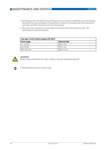
5 MAINTENANCE AND SERVICE<br />
<strong>OPTIFLUX</strong><br />
• Carefully pull the mounting frame with electronics unit almost completely out of the housing,<br />
disconnect the long rectangular (14-pole) blue connector at the back-end of the electronics<br />
unit. Now carefully remove the unit from the housing.<br />
• The mains fuse is located in a fuse holder at the back-end of the electronics unit. The<br />
specifications must be as follows:<br />
Fuse type: 5 x 20 mm (H) according to IEC 60127<br />
Power supply<br />
Electrical data<br />
12...24 V DC 250 V / 2 A<br />
24 V AC/DC 250 V / 2 A<br />
100...230 V AC 250 V / 1,6 A<br />
WARNING!<br />
Before reassembling the unit, refer to Before and after opening on page 33.<br />
• Reassemble the unit in reverse order.<br />
34<br />
www.krohne.com 11/2008 • 7.30948.24.00