OPTIFLUX Handbook
OPTIFLUX Handbook
OPTIFLUX Handbook

You also want an ePaper? Increase the reach of your titles
YUMPU automatically turns print PDFs into web optimized ePapers that Google loves.
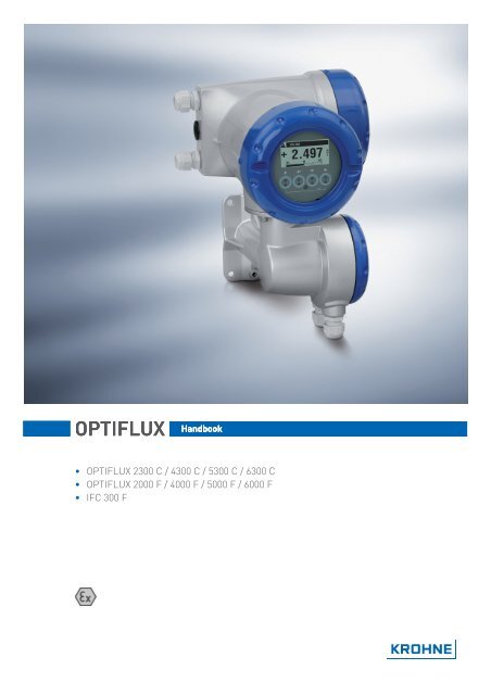
<strong>OPTIFLUX</strong><br />
<strong>Handbook</strong><br />
• <strong>OPTIFLUX</strong> 2300 C / 4300 C / 5300 C / 6300 C<br />
• <strong>OPTIFLUX</strong> 2000 F / 4000 F / 5000 F / 6000 F<br />
• IFC 300 F
: IMPRINT ::::::::::::::::::::::::::::::::::::::::::<br />
<strong>OPTIFLUX</strong><br />
All rights reserved. It is prohibited to reproduce this documentation, or any part thereof, without<br />
the prior written authorisation of KROHNE Messtechnik GmbH & Co. KG.<br />
Subject to change without notice.<br />
Copyright 2008 by<br />
KROHNE Messtechnik GmbH & Co.KG - Ludwig-Krohne-Straße 5 - 47058 Duisburg<br />
2<br />
www.krohne.com 11/2008 • 7.30948.24.00
<strong>OPTIFLUX</strong><br />
CONTENTS<br />
1 Introduction ................................................................................... 5<br />
1.1 Safety instructions from the manufacturer......................................................... 5<br />
1.1.1 Disclaimer.................................................................................................................. 5<br />
1.1.2 Product liability and warranty ................................................................................... 5<br />
1.1.3 Information concerning the documentation ............................................................. 5<br />
1.1.4 Display conventions ................................................................................................... 6<br />
1.1.5 Manufacturer ............................................................................................................. 6<br />
1.2 Safety instructions for the operator .................................................................... 7<br />
1.3 Approvals ............................................................................................................. 8<br />
1.4 <strong>OPTIFLUX</strong> 2000 / 4000.......................................................................................... 9<br />
1.4.1 Compact versions ...................................................................................................... 9<br />
1.4.2 Field versions.............................................................................................................9<br />
1.5 <strong>OPTIFLUX</strong> 5000................................................................................................... 11<br />
1.5.1 Compact versions .................................................................................................... 11<br />
1.5.2 Field versions........................................................................................................... 11<br />
1.6 <strong>OPTIFLUX</strong> 6000................................................................................................... 13<br />
1.6.1 Compact versions .................................................................................................... 13<br />
1.6.2 Field versions........................................................................................................... 13<br />
1.7 IFC 300................................................................................................................ 14<br />
1.8 Marking labels ................................................................................................... 15<br />
2 Temperature limits...................................................................... 16<br />
2.1 <strong>OPTIFLUX</strong> 2000 / 4000........................................................................................ 16<br />
2.1.1 Compact versions .................................................................................................... 16<br />
2.1.2 Field versions........................................................................................................... 17<br />
2.2 <strong>OPTIFLUX</strong> 5000................................................................................................... 19<br />
2.2.1 Compact versions .................................................................................................... 19<br />
2.2.2 Field versions........................................................................................................... 20<br />
2.3 <strong>OPTIFLUX</strong> 6000................................................................................................... 21<br />
2.3.1 Compact versions .................................................................................................... 21<br />
2.3.2 Field versions........................................................................................................... 21<br />
2.4 IFC 300 F............................................................................................................. 22<br />
3 Connection diagrams for field versions ...................................... 23<br />
3.1 Signal cable A..................................................................................................... 23<br />
3.2 Signal cable B.................................................................................................... 24<br />
3.3 Equipotential bonding ........................................................................................ 24<br />
3.4 Signal cable connections ................................................................................... 25<br />
4 Electrical connections ................................................................. 26<br />
4.1 Installation instructions..................................................................................... 26<br />
4.2 Connection of IFC 300 ........................................................................................ 28<br />
4.3 Input/output connnections................................................................................. 30<br />
11/2008 • 7.30948.24.00<br />
www.krohne.com<br />
3
CONTENTS<br />
<strong>OPTIFLUX</strong><br />
5 Maintenance and service............................................................. 33<br />
5.1 Maintenance....................................................................................................... 33<br />
5.2 Before and after opening ................................................................................... 33<br />
5.3 Replacement of mains fuse ............................................................................... 33<br />
6 KROHNE measuring technology - Product overview................... 36<br />
4 www.krohne.com 11/2008 • 7.30948.24.00
<strong>OPTIFLUX</strong><br />
INTRODUCTION 1<br />
1.1 Safety instructions from the manufacturer<br />
1.1.1 Disclaimer<br />
The manufacturer will not be liable for any damage of any kind by using its product, including,<br />
but not limited to direct, indirect, incidental, punitive and consequential damages.<br />
This disclaimer does not apply in case the manufacturer has acted on purpose or with gross<br />
negligence. In the event any applicable law does not allow such limitations on implied warranties<br />
or the exclusion of limitation of certain damages, you may, if such law applies to you, not be<br />
subject to some or all of the above disclaimer, exclusions or limitations.<br />
Any product purchased from the manufacturer is warranted in accordance with the relevant<br />
product documentation and our Terms and Conditions of Sale.<br />
The manufacturer reserves the right to alter the content of its documents, including this<br />
disclaimer in any way, at any time, for any reason, without prior notification, and will not be liable<br />
in any way for possible consequences of such changes.<br />
1.1.2 Product liability and warranty<br />
The operator shall bear responsibility for the suitability of the device for the specific purpose.<br />
The manufacturer accepts no liability for the consequences of misuse by the operator. Improper<br />
installation and operation of the devices (systems) will cause the warranty to be void. The<br />
respective "Standard Terms and Conditions" which form the basis for the sales contract shall<br />
also apply.<br />
1.1.3 Information concerning the documentation<br />
To prevent any injury to the user or damage to the device it is essential that you read the<br />
information in this document and observe applicable national standards, safety requirements<br />
and accident prevention regulations.<br />
If this document is not in your native language and if you have any problems understanding the<br />
text, we advise you to contact your local office for assistance. The manufacturer can not accept<br />
responsibility for any damage or injury caused by misunderstanding of the information in this<br />
document.<br />
This document is provided to help you establish operating conditions, which will permit safe and<br />
efficient use of this device. Special considerations and precautions are also described in the<br />
document, which appear in the form of underneath icons.<br />
11/2008 • 7.30948.24.00<br />
www.krohne.com<br />
5
1 INTRODUCTION<br />
<strong>OPTIFLUX</strong><br />
1.1.4 Display conventions<br />
The following symbols are used to help you navigate this documentation more easily:<br />
DANGER!<br />
This symbol designates safety advice on handling electricity.<br />
WARNING!<br />
These warning signs must be observed without fail. Even only partial disregarding such<br />
warnings can result in serious health damage, damage to the device itself or to parts of the<br />
operator’s plant.<br />
CAUTION!<br />
These warnings must be observed without fail. Even only partial disregarding such warnings can<br />
lead to improper functioning of the device.<br />
LEGAL NOTICE!<br />
This symbol designates information on statutory directives and standards.<br />
INFORMATION!<br />
This symbol designates important information for the handling of the device.<br />
• HANDLING<br />
This symbol designates all instructions for actions to be carried out by the operator in the<br />
specified sequence.<br />
i<br />
CONSEQUENCE<br />
This symbol designates all important consequences of the previous actions.<br />
1.1.5 Manufacturer<br />
This instrument is developed and manufactured by:<br />
KROHNE Altometer<br />
Kerkeplaat 12<br />
3313 LC Dordrecht<br />
The Netherlands<br />
For information, maintenance or service please contact your nearest local KROHNE<br />
representative.<br />
6<br />
www.krohne.com 11/2008 • 7.30948.24.00
<strong>OPTIFLUX</strong><br />
INTRODUCTION 1<br />
1.2 Safety instructions for the operator<br />
WARNING!<br />
• Do not change the device. Unauthorized changes affect the explosion safety of the devices.<br />
• The prescriptions and regulations as well as the electrical data described in the EC type<br />
examination certificate must be obeyed.<br />
• Beside the instructions for electrical installations in non-hazardous locations according to<br />
the applicable national standard (equivalent to HD 384 or IEC 364, e.g. VDE 0100), especially<br />
the regulations in EN 60079-14 "Electrical installations in hazardous locations", equivalent<br />
national standard (e.g. DIN VDE 0165 Part 1) or dust hazardous areas such as EN 61241-14<br />
must be complied with!<br />
• Installation, establishment, utilization and maintenance are only allowed to be executed by<br />
personnel with an education in explosion safety!<br />
These additional instructions are an extension to the handbook. All technical information as<br />
described in the handbook is applicable, when not specifically excluded, completed or replaced<br />
by the instructions in these additional instructions.<br />
11/2008 • 7.30948.24.00<br />
www.krohne.com<br />
7
1 INTRODUCTION<br />
<strong>OPTIFLUX</strong><br />
1.3 Approvals<br />
The flowmeter system consists of a flow sensor and a signal converter. The approval numbers<br />
are:<br />
compact versions:<br />
• <strong>OPTIFLUX</strong> 2300 C (= <strong>OPTIFLUX</strong> 2000 + IFC 300):<br />
KEMA 04 ATEX 2077 X<br />
• <strong>OPTIFLUX</strong> 4300 C (= <strong>OPTIFLUX</strong> 4000 + IFC 300):<br />
KEMA 04 ATEX 2077 X<br />
• <strong>OPTIFLUX</strong> 5300 C (= <strong>OPTIFLUX</strong> 5000 + IFC 300):<br />
KEMA 04 ATEX 2127 X<br />
• <strong>OPTIFLUX</strong> 6300 C (= <strong>OPTIFLUX</strong> 6000 + IFC 300):<br />
KEMA 04 ATEX 2214<br />
field versions:<br />
• <strong>OPTIFLUX</strong> 2000 F + IFC 300 F:<br />
KEMA 04 ATEX 2125 X + KEMA 04 ATEX 2166<br />
• <strong>OPTIFLUX</strong> 4000 F + IFC 300 F:<br />
KEMA 04 ATEX 2125 X + KEMA 04 ATEX 2166<br />
• <strong>OPTIFLUX</strong> 5000 F + IFC 300 F:<br />
KEMA 04 ATEX 2126 X + KEMA 04 ATEX 2166<br />
• <strong>OPTIFLUX</strong> 6000 F + IFC 300 F:<br />
KEMA 07 ATEX 0020 X + KEMA 04 ATEX 2166<br />
INFORMATION!<br />
All type examination certificates can be downloaded from the website.<br />
8<br />
www.krohne.com 11/2008 • 7.30948.24.00
<strong>OPTIFLUX</strong><br />
INTRODUCTION 1<br />
1.4 <strong>OPTIFLUX</strong> 2000 / 4000<br />
1.4.1 Compact versions<br />
<strong>OPTIFLUX</strong> 2300 C / 4300 C is certified as a group II, category 2 GD equipment, if fitted with an IFC<br />
300 signal converter without Ex ia signal in/outputs or as a group II, category 2 (1) GD equipment,<br />
if fitted with a signal converter with Ex ia signal in/outputs.<br />
It is therefore suitable for installation in gas hazardous areas zone 1 or 2, gas group IIC,<br />
temperature class T6 (or T5)...T3 and dust hazardous areas zone 21 or zone 22, surface<br />
temperature T85...150°C. Additionally, the Ex ia signal inputs/outputs of the signal converter<br />
may run or originate from a Zone 0 Gas hazardous area.<br />
Converter housing, connection compartment: with power supply (terminals L, N / L+, L-) and I/O<br />
connections (terminals A, A+, A-, B, B-, C, C-, D and D-):<br />
Ex e (Increased safety), optionally: Ex d (Flameproof Enclosure). For certain versions of the<br />
signal converter the terminals A, A+, A-, B, B-, C, C-, D and D- are additionally Ex ia (Intrinsic<br />
safety). Consult the table with the CG numbers for more details.<br />
Converter housing, electronics compartment: Ex d (Flameproof enclosure).<br />
EEx marking <strong>OPTIFLUX</strong> 2300 C / 4300 C:<br />
Nominal diameter<br />
EEx e connection compartment,<br />
II 2 GD or II 2(1) GD<br />
10...20 ("me") EEx dme [ia] IIC T6...T3<br />
T85...150°C<br />
EEx d connection compartment,<br />
II 2 GD or II 2(1) GD<br />
EEx dme [ia] IIC T6...T3<br />
T85...150°C<br />
25...150 ("d") EEx de [ia] IIC T6...T3 T85...150°C EEx d [ia] IIC T6...T3 T85...150°C<br />
200...300 ("qe") EEx dqe [ia] IIC T6...T3<br />
T85...150°C<br />
EEx dqe [ia] IIC T6...T3<br />
T85...150°C<br />
350...3000 ("e") EEx de [ia] IIC T6...T3 T85...150°C EEx de [ia] IIC T6...T3 T85...150°C<br />
Optional:<br />
25...150 ("qe") EEx dqe [ia] IIC T5...T3<br />
T85...150°C<br />
EEx dqe [ia] IIC T5...T3<br />
T85...150°C<br />
1.4.2 Field versions<br />
<strong>OPTIFLUX</strong> 2000 F / 4000 F is certified as group II, category 2 GD equipment for gas hazardous<br />
areas zone 1 and 2, gas group IIC, temperature classes T6 (or T5) ... T3 and dust hazardous areas<br />
zone 21 and 22, surface temperature T85…150/160/180°C.<br />
The connection box contains terminals for the connection of the field current and electrode<br />
circuits:<br />
Field current circuit, in type of protection "Increased safety" (Ex e), terminals 7,8 and 9:<br />
U < 40 V (switched DC voltage, alternately +40 and -40 V), I = 125 mA (injected square wave<br />
current),<br />
Electrode terminals, in type of protection "Intrinsic safety" (Ex ia), terminals 1, 2, 3, and 4:<br />
U i = 20 V , I i = 175 mA, C i ≈ 0 nF, L i ≈ 0 mH.<br />
The before mentioned intrinsically safe circuits shall, from the safety point of view, be<br />
considered to be connected to ground.<br />
The cable gland for the electrode circuit is - as intrinsic safe circuit - marked with a blue O-ring.<br />
11/2008 • 7.30948.24.00<br />
www.krohne.com<br />
9
1 INTRODUCTION<br />
<strong>OPTIFLUX</strong><br />
EEx marking <strong>OPTIFLUX</strong> 2000 F / 4000 F:<br />
Nominal diameter<br />
II 2 GD<br />
10...20 ("me") EEx me ia IIC T6...T3 T85...150°C<br />
25...150 ("d") EEx de ia IIC T6...T3 T85...180°C<br />
200...300 ("qe") EEx qe ia IIC T6...T3 T85...150°C<br />
350...3000 ("e") EEx e ia IIC T6...T3 T85...160°C<br />
Optional:<br />
25...150 ("qe") EEx qe ia IIC T5...T3 T85...180°C<br />
10<br />
www.krohne.com 11/2008 • 7.30948.24.00
<strong>OPTIFLUX</strong><br />
INTRODUCTION 1<br />
1.5 <strong>OPTIFLUX</strong> 5000<br />
1.5.1 Compact versions<br />
<strong>OPTIFLUX</strong> 5300 C is certified as group II, category 2 GD equipment if fitted with an IFC 300 signal<br />
converter without Ex ia signal in/outputs or as a group II, category 2 (1) GD equipment, if fitted<br />
with a signal converter with Ex ia signal in/outputs. It is therefore suitable for installation in gas<br />
hazardous areas zone 1 and 2, gas group IIC, temperature class T6…T3 and dust hazardous<br />
areas zone 21 or zone 22, surface temperature T85...180°C. Additionally, the Ex ia signal<br />
in/outputs of the signal converter may run or originate from a Zone 0 gas hazardous area.<br />
The sensor is available in "sandwich" and in "flange" version.<br />
Converter housing, connection compartment:<br />
with power supply (terminals L, N / L+, L-) and I/O connections (terminals A, A+, A-, B, B-, C, C-,<br />
D and D-): Ex e (increased safety), optionally: Ex d (Flameproof enclosure). For certain versions<br />
of the signal converter the terminals A, A+, A-, B, B-, C, C-, D and D- are additionally Ex ia<br />
(Intrinsic safety). Consult the table with CG numbers for details.<br />
Converter housing, electronics compartment:<br />
Ex d (Flameproof enclosure).<br />
EEx marking <strong>OPTIFLUX</strong> 5300 C "sandwich":<br />
Nominal diameter<br />
EEx e connection compartment,II<br />
2 GD or II 2(1) GD<br />
2,5...15 EEx dme [ia] IIC T6...T3<br />
T85...150°C<br />
EEx d connection compartment,II<br />
2 GD or II 2(1) GD<br />
EEx dme [ia] IIC T6...T3<br />
T85...150°C<br />
25...100 EEx de [ia] IIC T6...T3 T85...150°C EEx d [ia] IIC T6...T3 T85...150°C<br />
EEx marking <strong>OPTIFLUX</strong> 5300 C "flange":<br />
Nominal diameter<br />
EEx e or EEx d connection compartment,II 2 GD or<br />
II 2(1) GD<br />
15...100 EEx d e [ia] mb IIC T6...T3 T85...150°C<br />
1.5.2 Field versions<br />
<strong>OPTIFLUX</strong> 5000 F is certified as group II, category 2 GD equipment for gas hazardous areas zone<br />
1 and 2, gas group IIC, temperature classes T6…T3 and dust hazardous areas zone 21 and 22,<br />
surface temperature T85...180°C.<br />
The connection box contains terminals for the connection of the field current and electrode<br />
circuits:<br />
Field current circuit, in type of protection "Increased safety" (Ex e), terminals 7,8 and 9:<br />
U < 40 V (switched DC voltage, alternately +40 and -40 V), I = 125 mA (injected square wave<br />
current),<br />
11/2008 • 7.30948.24.00<br />
www.krohne.com<br />
11
1 INTRODUCTION<br />
<strong>OPTIFLUX</strong><br />
Electrode circuit, in type of protection "Intrinsic safety" (Ex ia), terminals 1, 2, 3, and 4:<br />
U i = 20 V , I i = 175 mA, C i ≈ 0 nF, L i ≈ 0 mH.<br />
The before mentioned intrinsically safe circuits shall, from the safety point of view, be<br />
considered to be connected to ground.<br />
The cable gland for the electrode circuit is - as intrinsic safe circuit - marked with a blue O-ring.<br />
The connection box contains terminals for the connection of the field current and electrode<br />
circuits:<br />
Field current terminals, in type of protection "Increased safety" (Ex e), terminals 7, 8 and 9:<br />
U < 40 V (switched DC voltage, alternately +40 and -40 V), I = 125 mA (injected square wave<br />
current).<br />
Electrode terminals, in type of protection "Intrinsic safety"(Ex ia), terminals 1, 2, 3 and 4:<br />
U i = 20 V, I i = 175 mA, C i ≈ 0 nF, L i ≈ 0 mH.<br />
The before mentioned intrinsically safe circuits shall, from the safety point of view, be<br />
considered to be connected to ground.<br />
The cable gland for the electrode circuit is - as intrinsic safe circuit - marked with a blue O-ring.<br />
EEx marking <strong>OPTIFLUX</strong> 5000 F "sandwich":<br />
Nominal diameter<br />
2,5...15 II 2 GD EEx me ia IIC T6...T3 T85...180°C<br />
25...100 II 2 GD EEx de ia IIC T6...T3 T85...180°C<br />
12<br />
www.krohne.com 11/2008 • 7.30948.24.00
<strong>OPTIFLUX</strong><br />
INTRODUCTION 1<br />
1.6 <strong>OPTIFLUX</strong> 6000<br />
1.6.1 Compact versions<br />
<strong>OPTIFLUX</strong> 6300 C is certified as group II, category 2 GD equipment, if fitted with an IFC 300 signal<br />
converter without Ex ia signal in/outputs or as a group II, category 2 (1) GD equipment, if fitted<br />
with a signal converter with Ex ia signal in/outputs. It is therefore suitable for installation in gas<br />
hazardous areas zone 1 and 2, gas group IIC, temperature classes T6…T3 and dust hazardous<br />
areas zone 21 and 22, surface temperature T150°C. Additionally, the Ex ia signal in/outputs of the<br />
signal converter may run or originate from a Zone 0 gas hazardous area.<br />
Converter housing, connection compartment: with power supply (terminals L, N / L+, L-) and I/O<br />
connections (terminals A, A+, A-, B, B-, C, C-, D and D-):<br />
Ex e (Increased safety), optionally: EEx d (Flameproof Enclosure).<br />
For certain versions of the signal converter, the terminals A, A+, A-, B, B-, C, C-, D and D- are<br />
additionally Ex ia (Intrinsic safety). Consult the tables with CG numbers for details.<br />
Converter housing, electronics compartment: Ex d (Flameproof Enclosure)<br />
EEx marking <strong>OPTIFLUX</strong> 6300 C:<br />
Nominal diameter<br />
EEx e connection compartment,<br />
EEx d connection compartment,<br />
II 2 GD or II 2 (1) GD<br />
II 2 GD or II 2 (1) GD<br />
25...80 II 2 GD Ex e ia mb IIC T6...T3 T180°C<br />
1.6.2 Field versions<br />
<strong>OPTIFLUX</strong> 6000 F is certified as group II, category 2 GD equipment for gas hazardous areas zone<br />
1 and 2, gas group IIC, temperature classes T6…T3 and dust hazardous areas zone 21 and 22,<br />
surface temperature T180°C.<br />
The connection box contains terminals for the connection of the field current and electrode<br />
circuits:<br />
Field current circuit, in type of protection "Increased safety" (Ex e), terminals 7,8 and 9:<br />
U < 50 V (switched DC voltage, alternately +40 and -40 V), I = 125 mA (injected square wave<br />
current),<br />
Electrode circuit, in type of protection "Intrinsic safety" (Ex ia), terminals 1, 2, 3, and 4:<br />
U i = 20 V , I i = 175 mA, C i ≈ 0 nF, L i ≈ 0 mH.<br />
The before mentioned intrinsically safe circuits shall, from the safety point of view, be<br />
considered to be connected to ground.<br />
The cable gland for the electrode circuit is - as intrinsic safe circuit - marked with a blue O-ring.<br />
Ex marking <strong>OPTIFLUX</strong> 6000 F:<br />
Nominal diameter<br />
25...80 II 2 GD Ex e ia mb IIC T6...T3 T180°C<br />
11/2008 • 7.30948.24.00<br />
www.krohne.com<br />
13
1 INTRODUCTION<br />
<strong>OPTIFLUX</strong><br />
1.7 IFC 300<br />
The IFC 300 is certified as a group II, category 2 GD equipment, if fitted without Ex ia signal<br />
in/outputs or as a group II, category 2 (1) GD equipment, if fitted with Ex ia signal inputs/outputs.<br />
It is therefore suitable for installation in gas hazardous areas zone 1 or 2, gas group IIC,<br />
temperature class T6 and dust hazardous areas zone 21 or 22, surface temperature T85°C.<br />
Additionally, The Ex ia signal in/outputs of the converter may run or originate from a zone 0 gas<br />
hazardous area.<br />
In the IFC 300 signal converter the following types of protections are used:<br />
Converter housing, connection compartment: with power supply (terminals L, N / L+, L-) and I/O<br />
connections (terminals A, A+, A-, B, B-, C, C-, D and D- ): Ex e (Increased safety). Optionally<br />
compact flowmeters have Ex d (Flameproof Enclosure). For certain versions of the signal<br />
converter the terminals A, A+, A-, B, B-, C, C-, D and D- are additionally Ex ia (Intrinsic safety).<br />
Consult the table with CG numbers for details.<br />
Converter housing, electronics compartment: Ex d (Flameproof enclosure)<br />
Field current circuit, in type of protection "Increased safety" (Ex e), terminals 7,8 and 9:<br />
U < 40 V (switched DC voltage, alternately +40 and -40 V), I = 125 mA (injected square wave<br />
current). The field current source is protected by 2 TR5 fuses, rated value 160 mA. The maximum<br />
prospective short circuit current is restricted to 35 A.<br />
Electrode terminals, in type of protection "Intrinsic safety" (Ex ia), terminals 1, 2, 20, 3, 30, 4 and<br />
40:<br />
U o = 14 V , I o = 70 mA, P o = 300 mW (lineair), C o = 430 nF, L o = 2 mH.<br />
The Ex marking is II 2 GD EEx de [ia] IIC T6 T85°C for converters with non Ex ia signal in/outputs<br />
or II 2 (1) GD EEx de [ia] IIC T6 T85°C for converters with Ex ia signal in/outputs.<br />
14<br />
www.krohne.com 11/2008 • 7.30948.24.00
<strong>OPTIFLUX</strong><br />
INTRODUCTION 1<br />
1.8 Marking labels<br />
The data sticker on the connection box of the separate flow sensor typically contains the<br />
following information.<br />
Figure 1-1: Data sticker on sensor<br />
1 Name and address of the manufacturer<br />
2 CE sign with number(s) of notified body / bodies<br />
3 Specific sign for explosion protection<br />
4 Number of EC type examination certificate<br />
5 General EEx notes and warnings<br />
6 Specific EEx notes and warnings<br />
7 Type designation of the flowmeter<br />
The data sticker on the converter typically contains the following information.<br />
Figure 1-2: Example of a nameplate for compact version<br />
1 Approvals-related information: Ex approval, EC type test certificate, hygienic approvals, etc.<br />
2 Approvals-related thresholds<br />
3 Approvals-related connection data of the inputs/outputs; V m = max. power<br />
4 Approvals-related data (e.g. accuracy class, measuring range, temperature threshold, pressure threshold and viscosity<br />
threshold)<br />
5 Approvals-related pressure and temperature thresholds<br />
6 Power; protection category; materials of parts in contact with media<br />
7 GK/GKL values (measuring sensor constants); size (mm /inches); field frequency<br />
8 Product designation, serial number and date of manufacture<br />
11/2008 • 7.30948.24.00<br />
www.krohne.com<br />
15
2 TEMPERATURE LIMITS<br />
<strong>OPTIFLUX</strong><br />
The temperature limits apply under the following conditions:<br />
• The instrument is installed and operated in accordance with the installation directions given<br />
in the installation and operating instructions.<br />
• The instrument is not heated up by any additional heat radiation (direct solar radiation, heat<br />
from adjacent plant parts) so causing it to operate above the permissible ambient<br />
temperature range.<br />
• Insulation is not hindering free ventilation of the signal converter housing.<br />
2.1 <strong>OPTIFLUX</strong> 2000 / 4000<br />
2.1.1 Compact versions<br />
• The <strong>OPTIFLUX</strong> 2300 C / 4300 C is suitable for an ambient temperature range of -40…+60°C.<br />
• For dust hazardous areas, the maximum surface temperature is equal to the process<br />
temperature with a minimum of 85°C.<br />
• The minimum process temperature for all DN sizes is -40°C.<br />
• The maximum process temperature is determined by the temperature class T6/T5...T3 of the<br />
gas hazardous area of concern, the maximum ambient temperature (T a ), and the nominal<br />
diameter. The temperature range is often limited further by the liner type used (refer to the<br />
Quick Start).<br />
DN10...20 ("me")<br />
Temperature class<br />
Max. process temperature Tp [°C]<br />
T a ≤ 40°C 40 < T a ≤ 50°C 50 < T a ≤ 60°C<br />
T6 70 60 -<br />
T5 95 85 60<br />
T4 130 130 60<br />
T3 150 150 1 60<br />
1 140°C for versions with stainless steel converter housing<br />
DN25...150 ("d")<br />
Temperature class<br />
Max. process temperature Tp [°C]<br />
T a ≤ 40°C 40 < T a ≤ 50°C 50 < T a ≤ 60°C<br />
T6 80 80 80 1<br />
T5 95 95 80 1<br />
T4 130 130 80 1<br />
T3 150 150 2 80 1<br />
1 60°C for versions with stainless steel converter housing<br />
2 140°C for versions with stainless steel converter housing<br />
16<br />
www.krohne.com 11/2008 • 7.30948.24.00
<strong>OPTIFLUX</strong><br />
TEMPERATURE LIMITS 2<br />
DN25...150 ("qe")<br />
Temperature class<br />
Max. process temperature Tp [°C]<br />
T a ≤ 40°C 40 < T a ≤ 50°C 50 < T a ≤ 60°C<br />
T5 50 - -<br />
T4 100 95 80 1<br />
T3 150 150 2 80 1<br />
1 60°C for versions with stainless steel converter housing<br />
2 140°C for versions with stainless steel converter housing<br />
DN200...300 ("qe") and DN350...3000 ("e")<br />
Temperature class<br />
Max. process temperature Tp [°C]<br />
T a ≤ 40°C 40 < T a ≤ 50°C 50 < T a ≤ 60°C<br />
T6 80 80 75 1<br />
T5 95 95 80 1<br />
T4 130 130 80 1<br />
T3 150 150 2 80 1<br />
T3 3 130 130 80 1<br />
1 60°C for versions with stainless steel converter housing<br />
2 140°C for versions with stainless steel converter housing<br />
3 For some versions the process temperature is restricted to 130 °C. This version is identified by extra text (/RT) on the<br />
data sticker<br />
2.1.2 Field versions<br />
• In general the <strong>OPTIFLUX</strong> 2000 F / 4000 F flow sensors are suitable for an ambient<br />
temperature range of -40...+60°C.<br />
• For dust hazardous areas the maximum surface temperature is equal to the process<br />
temperature T p with a minimum of 85°C.<br />
• The minimum process temperature is -40°C.<br />
• The maximum process temperature Tp is dependent on the required temperature class<br />
T6/T5...T3, the diameter and the maximum ambient temperature T a . The temperature range<br />
is often limited further by the liner type used (refer to the Quick Start).<br />
DN10...20 ("me")<br />
Temperature class<br />
Max. process temperature Tp [°C]<br />
T a ≤ 40°C 40 < T a ≤ 50°C 50 < T a ≤ 60°C<br />
T6 75 70 70<br />
T5 95 90 75<br />
T4 130 115 75<br />
T3 150 115 75<br />
11/2008 • 7.30948.24.00<br />
www.krohne.com<br />
17
2 TEMPERATURE LIMITS<br />
<strong>OPTIFLUX</strong><br />
DN25...150 ("d")<br />
Temperature class<br />
Max. process temperature Tp [°C]<br />
T a ≤ 40°C 40 < T a ≤ 50°C 50 < T a ≤ 60°C<br />
T6 70 70 70<br />
T5 85 85 85<br />
T4 120 120 120<br />
T3 180 180 180<br />
Use heat resistant Not needed 155 105<br />
cables for T p above: 1<br />
1 Cables must withstand a continuous operating temperature of 85°C.<br />
DN200...300 ("qe")<br />
Temperature class Max. process temperature Tp [°C]<br />
T a ≤ 40°C 40 < T a ≤ 50°C 50 < T a ≤ 60°C<br />
T6 75 70 70<br />
T5 95 90 75<br />
T4 130 115 75<br />
T3 150 115 75<br />
DN350...3000 ("e")<br />
Temperature class<br />
Max. process temperature Tp [°C]<br />
T a ≤ 40°C 40 < T a ≤ 50°C 50 < T a ≤ 60°C<br />
T6 60 60 60<br />
T5 80 75 75<br />
T4 115 115 115<br />
T3 1 160 150 140<br />
Use heat resistant Not needed 145 110<br />
cables for T p above: 2<br />
1 For some versions the process temperature for T3 is restricted to 130°C. This version is identified by extra text (/RT)<br />
on the data sticker.<br />
2 Cables must withstand a continuous operating temperature of 85°C.<br />
DN25...150 ("qe")<br />
Temperature class<br />
Max. process temperature Tp [°C]<br />
T a ≤ 40°C 40 < T a ≤ 50°C 50 < T a ≤ 60°C<br />
T5 60 55 -<br />
T4 110 105 100<br />
T3 180 180 180<br />
Use heat resistant Not needed 155 105<br />
cables for T p above: 1<br />
1 Cables must withstand a continuous operating temperature of 85°C.<br />
18<br />
www.krohne.com 11/2008 • 7.30948.24.00
<strong>OPTIFLUX</strong><br />
TEMPERATURE LIMITS 2<br />
2.2 <strong>OPTIFLUX</strong> 5000<br />
The maximum process temperature T p is dependent on the required temperature class T6...T3<br />
and the maximum ambient temperature T a .<br />
2.2.1 Compact versions<br />
Sandwich versions<br />
• For dust hazardous areas, the maximum surface temperature is equal to the process<br />
temperature with a minimum of 85 °C.<br />
• The <strong>OPTIFLUX</strong> 5300 C "sandwich" is suitable for an ambient temperature range of -20...60°C<br />
(DN2,5...15) or -40...+60°C (DN25...100).<br />
• The minimum process temperature is -20°C (DN2,5...15) or -40°C (DN25...100).<br />
Temperature class<br />
Max. process temperature Tp [°C]<br />
T a ≤ 40°C 40 < T a ≤ 50°C 50 < T a ≤ 60°C<br />
T6 60 55 -<br />
T5 75 75 70<br />
T4 115 115 75<br />
T3 150 135 75<br />
Flange versions<br />
• The <strong>OPTIFLUX</strong> 5300 C "flange" is suitable for an ambient temperature range of -40...+60°C.<br />
• The minimum process temperature is -40°C.<br />
Temperature class<br />
Max. surface<br />
temperature for<br />
dust [°C]<br />
Max. process temperature Tp [°C]<br />
T a ≤ 40°C 40 < T a ≤ 50°C 50 < T a ≤ 60°C<br />
T6 85 80 80 60<br />
T5 100 95 95 60<br />
T4 135 135 130 60<br />
T3 150 150 145 60<br />
11/2008 • 7.30948.24.00<br />
www.krohne.com<br />
19
2 TEMPERATURE LIMITS<br />
<strong>OPTIFLUX</strong><br />
2.2.2 Field versions<br />
Sandwich versions<br />
• The flow sensor is suitable for an ambient temperature range of -20...65°C (DN2,5...15) or -<br />
40...+65°C (DN25...100).<br />
• The minimum process temperature is -20°C (DN2,5...15) or -40°C (DN25...100).<br />
Temperature class<br />
(for gasses)<br />
Maximum surface<br />
temperature for<br />
dust [°C]<br />
Max. process temperature Tp [°C]<br />
T a ≤ 40°C 40 < T a ≤ 50°C 50 < T a ≤ 65°C<br />
T6 85 65 65 60<br />
T5 95 85 85 75<br />
T4 130 125 125 115<br />
T3 180 180 165 140<br />
Use heat<br />
resistance cable<br />
for T p above: 1<br />
165 130 100<br />
1 Cables must withstand a continuous operating temperature of 85 °C.<br />
Flange versions<br />
• The flow sensor is suitable for an ambient temperature range of -40...65°C (DN15...100).<br />
• The minimum process temperature is -40°C.<br />
Temperature class<br />
(for gasses)<br />
Maximum surface<br />
temperature for<br />
dust [°C]<br />
Max. process temperature Tp [°C]<br />
T a ≤ 40°C 40 < T a ≤ 50°C 50 < T a ≤ 65°C<br />
T6 85 80 80 75<br />
T5 95 95 95 95<br />
T4 130 130 130 130<br />
T3 180 180 180 145<br />
Use heat<br />
resistance cable<br />
for T p above: 1<br />
never 165 90<br />
1 Cables must withstand a continuous operating temperature of 85 °C.<br />
20<br />
www.krohne.com 11/2008 • 7.30948.24.00
<strong>OPTIFLUX</strong><br />
TEMPERATURE LIMITS 2<br />
2.3 <strong>OPTIFLUX</strong> 6000<br />
2.3.1 Compact versions<br />
• The flow sensor is suitable for an ambient temperature range of -40...+60°C.<br />
• The minimum process temperature is -40°C.<br />
• For dust hazardous areas the maximum surface temperature is 150°C at an ambient<br />
temperature T a ≤ 60°C.<br />
• The maximum process temperature T p depends on the required temperature class T6...T3<br />
and the maximum ambient temperature T a .<br />
Temperature class<br />
Max. process temperature Tp [°C]<br />
T a ≤ 40°C 40 < T a ≤ 50°C 50 < T a ≤ 60°C<br />
T6 75 70 65<br />
T5 95 95 85<br />
T4 130 130 85<br />
T3 150 150 85<br />
Use heat resistant Not needed 150 110<br />
cables for T p above: 1<br />
1 Cables must withstand a continuous operating temperature of 85°C.<br />
2.3.2 Field versions<br />
• The flow sensor is suitable for an ambient temperature range of -40...+60°C (DN25...80).<br />
• For dust hazardous areas the maximum surface temperature is 180°C at an ambient<br />
temperature T a ≤ 60°C.<br />
• The minimum process temperature is -40°C.<br />
• The maximum process temperature T p depends on the required temperature class T6...T3<br />
and the maximum ambient temperature T a .<br />
Temperature class<br />
Max. process temperature Tp [°C]<br />
T a ≤ 40°C 40 < T a ≤ 50°C 50 < T a ≤ 60°C<br />
T6 75 70 65<br />
T5 95 90 85<br />
T4 130 130 130<br />
T3 180 180 170<br />
Use heat resistant Not needed 150 110<br />
cables for T p above: 1<br />
1 Cables must withstand a continuous operating temperature of 85°C.<br />
11/2008 • 7.30948.24.00<br />
www.krohne.com<br />
21
2 TEMPERATURE LIMITS<br />
<strong>OPTIFLUX</strong><br />
2.4 IFC 300 F<br />
The signal converter IFC 300 F is suitable for an ambient temperature range of -40...+65°C.<br />
22<br />
www.krohne.com 11/2008 • 7.30948.24.00
<strong>OPTIFLUX</strong><br />
CONNECTION DIAGRAMS FOR FIELD VERSIONS 3<br />
In the case of field versions, the electrical connection between the sensor and the signal<br />
converter is established via a signal cable and a field current cable.<br />
The field current cable is no part of the supply and must be supplied by the user. It must be<br />
according EN 60079-14 clause 9.3 and 11.3 (Increased safety).<br />
The signal cable is part of the supply.<br />
3.1 Signal cable A<br />
The signal cable A is a double screen shielding cable, according to EN 60079-14 clause 12.2<br />
(Intrinsic safety).<br />
Figure 3-1: Construction of signal cable A<br />
1 Stranded drain wire (1) for the inner shield (10), 1.0 mm 2 Cu / AWG 17 (not insulated, bare)<br />
2 Insulated wire (2), 0.5 mm 2 Cu / AWG 20<br />
3 Insulated wire (3), 0.5 mm 2 Cu / AWG 20<br />
4 Outer sheath<br />
5 Insulation layers<br />
6 Stranded drain wire (6) for the outer shield (60)<br />
11/2008 • 7.30948.24.00<br />
www.krohne.com<br />
23
3 CONNECTION DIAGRAMS FOR FIELD VERSIONS<br />
<strong>OPTIFLUX</strong><br />
3.2 Signal cable B<br />
The signal cable B is a triple screen shielding cable, according to EN 60079-14 clause 12.2<br />
(Intrinsic safety).<br />
Figure 3-2: Construction of signal cable B<br />
1 Stranded drain wire for the inner shield (10), 1.0 mm 2 Cu / AWG 17 (not insulated, bare)<br />
2 Insulated conductor (2), 0.5 mm 2 Cu / AWG 20 with stranded drain wire (20) of the shield<br />
3 Insulated conductor (3), 0.5 mm 2 Cu / AWG 20 with stranded drain wire (30) of the shield<br />
4 Outer sheath<br />
5 Insulation layers<br />
6 Stranded drain wire (6) for the outer shield (60), 0.5 mm 2 Cu / AWG 20 (not insulated, bare)<br />
3.3 Equipotential bonding<br />
• As the Ex ia electrode circuits of the flow sensors are effectively grounded through the<br />
conductive liquid in the measuring tube, an equipotential bonding system must exist over the<br />
whole area in which the electrode circuits, including their wiring, are installed, conform EN<br />
60 079-14 clause 12.2.4.<br />
• The flowmeters <strong>OPTIFLUX</strong> 2000, 4000, 5000 and 6000, the electrode cable and the IFC 300 F<br />
signal converter must all be included in the equipotential bonding system of the hazardous<br />
area. If a single separate conductor is used for equipotential bonding, than this conductor<br />
must have a cross section of at least 4 mm 2 copper.<br />
• The separate equipotential bonding conductor between flowmeter and converter can be left<br />
out, if by other means (e.g. over bonding conductors over the metal piping system) a high<br />
level of assurance that potential equalization exists between flowmeter and converter is<br />
reached.<br />
24<br />
www.krohne.com 11/2008 • 7.30948.24.00
<strong>OPTIFLUX</strong><br />
CONNECTION DIAGRAMS FOR FIELD VERSIONS 3<br />
3.4 Signal cable connections<br />
Figure 3-3: Connecting with signal cable A<br />
1 Equipotential bonding, conductor ≥ 4 mm 2<br />
2 Field current cable acc. EN 60079-14 clause 9.3 and 11.3 (Increased safety)<br />
3 Signal cable A acc. EN 60079-14 clause 12.2 (Intrinsic safety)<br />
Figure 3-4: Connecting with signal cable B<br />
1 Equipotential bonding, conductor ≥ 4 mm 2<br />
2 Field current cable acc. EN 60079-14 clause 9.3 and 11.3 (Increased safety)<br />
3 Signal cable B acc. EN 60079-14 clause 12.2 (Intrinsic safety)<br />
11/2008 • 7.30948.24.00<br />
www.krohne.com<br />
25
4 ELECTRICAL CONNECTIONS<br />
<strong>OPTIFLUX</strong><br />
4.1 Installation instructions<br />
For IFC 300 F, <strong>OPTIFLUX</strong> 2000 F / 4000 F / 5000 F, <strong>OPTIFLUX</strong> 2300 C / 4300 C / 5300 C / 6300 C:<br />
When used in a potentially explosive atmosphere, requiring the use of apparatus of equipment<br />
category 2G, certified cable entry devices must be used that are suitable for the application and<br />
correctly installed.<br />
When used in a potentially explosive atmosphere, requiring the use of apparatus of equipment<br />
category 2D, certified cable entry devices with a degree of ingress protection of at least IP6x<br />
according to EN 60 529 must be used that are suitable for the application and correctly installed.<br />
Unused openings must be closed with suitable certified closing elements.<br />
With the use of conduits, a suitable certified sealing device such as a stopping box with setting<br />
compound must be provided immediately at the entrance to the flameproof enclosure.<br />
For IFC 300 F, <strong>OPTIFLUX</strong> 4300 C / 5300 C:<br />
To avoid voltage and current addition, the intrinsically safe circuits must be separated and wired<br />
to EN 60 079-14.<br />
For <strong>OPTIFLUX</strong> 6000 F:<br />
The cable glands and blanking elements must be in type of protection increades safety "e",<br />
suitable for the conditions of use and correctly installed. The devices must provide a degree of<br />
protection of at least IP64 according to EN 60 529.<br />
Additionally for <strong>OPTIFLUX</strong> 2000 F / 4000 F / 5000 F / 6000 F:<br />
The field coils in type of explosion protection "q" and "m" must be protected by a 160 mA fuse.<br />
The breaking capacity of the fuse must be in accordance with the prospective short circuit<br />
current of the supply. This concerns:<br />
<strong>OPTIFLUX</strong> 2000 F / 4000 F<br />
<strong>OPTIFLUX</strong> 5000 F "sandwich"<br />
<strong>OPTIFLUX</strong> 5000 F "flange"<br />
<strong>OPTIFLUX</strong> 6000 F<br />
DN10...20 ("me")<br />
DN200...300 ("qe")<br />
DN25...150 ("qe") (optional)<br />
DN2,5...15 ("me")<br />
DN15...100 ("mb")<br />
DN25...80 ("mb")<br />
26<br />
www.krohne.com 11/2008 • 7.30948.24.00
<strong>OPTIFLUX</strong><br />
ELECTRICAL CONNECTIONS 4<br />
INFORMATION!<br />
• The internal field coil fuses of an IFC 300 electronic unit fulfill the above mentioned<br />
requirement with respect to breaking capacity<br />
• The IFC 300 signal converter is delivered with two Ex e certified M20x1,5 cable glands and<br />
one Ex e certified M20x1,5 stopping plug in the connection compartment for power supply etc.<br />
and with two Ex e certified M20x1,5 cable glands in the connection box for the field current /<br />
electrode cables.<br />
• The <strong>OPTIFLUX</strong> 2000 F / 4000 F / 5000 F / 6000 F flow sensors are normally delivered with two<br />
Ex e certified M20x1,5 cable glands, clamping range Ø 6...12 mm<br />
• The <strong>OPTIFLUX</strong> 2300 C / 4300 C / 5300 C / 6300 C: flow meters are normally (connection<br />
compartment in type of Ex protection Ex e) delivered with two Ex e certified M20x1,5 cable<br />
glands, clamping range Ø 6...12 mm, and one Ex e certified M20x1,5 stopping plug.<br />
The optional <strong>OPTIFLUX</strong> 2300 C / 4300 C / 5300 C / 6300 C flow meters with connection<br />
compartment in type of Ex protection Ex d (flameproof enclosure) are normally delivered<br />
with one Ex d certified M20x1,5 stopping plug and two temporarily non-Ex certified simple<br />
plastic plugs. The purpose of these two plugs is only to keep the connection compartment<br />
free of dust and moisture during transport and storage.<br />
11/2008 • 7.30948.24.00<br />
www.krohne.com<br />
27
4 ELECTRICAL CONNECTIONS<br />
<strong>OPTIFLUX</strong><br />
4.2 Connection of IFC 300<br />
The flow sensors and the signal converter in field version must be incorporated in the<br />
equipotential bonding system of the installation. This can be established internally by connection<br />
of the protective earth (PE) conductor of the mains supply system to the internal PE clamp, or<br />
externally, by connecting a separate equipotential bonding conductor to the external U-clamp<br />
terminal (size M5) at respectively the flange of the mounting support (in case of compact<br />
instruments) or at the wall-mounting device (for signal converters in field version). A separate<br />
bonding conductor must have a cross-sectional area of at least 4 mm 2 .<br />
The display cover seals the electronics compartment of the converter housing and provides type<br />
of protection “flameproof enclosure”. The terminal compartment is default in type of protection<br />
“increased safety” and can optionally be performed as flameproof enclosure. The threaded joints<br />
formed by the covers and housing are a tight fit due to the requirements for type of protection<br />
“flameproof enclosure”. Screw the covers on and off with care and never use excessive force !<br />
Keep the screw-threads free of dirt and well-greased (e.g. with PTFE grease). The grease will<br />
help to prevent the threads from locking due to corrosion.<br />
To unscrew the covers, first release the interlocking devices (one at each cover). Therefore<br />
unscrew the M4 head screw with internal hexagon socket set using a No. 3 Allen key until the<br />
interlocking device can be turned. After the covers are screwed back onto the housing, make<br />
sure that the interlocking devices are properly refitted.<br />
WARNING!<br />
Allow the electronics to de-energize before opening the electronics compartment of the flow<br />
converter housing. Wait at least 35 minutes for T6 and 10 minutes for T5 before opening.<br />
Figure 4-1: Electrical connections<br />
1 protection cover<br />
2 PE grounding clamp<br />
3 N (or L-) terminal<br />
4 L (or L+) terminal<br />
28<br />
www.krohne.com 11/2008 • 7.30948.24.00
<strong>OPTIFLUX</strong><br />
ELECTRICAL CONNECTIONS 4<br />
Terminals<br />
L, N<br />
L+, L-<br />
A, A-, A+<br />
B, B-<br />
C, C-<br />
D, D-<br />
Function, electrical data<br />
Connections for mains supply, always non-Ex i<br />
100...230 V AC, +10%/-15%, 22 VA<br />
12...24 V DC, +30%/-25%, 12 W<br />
24 V AC, +10%/-15%, 22 VA<br />
24 V DC, +30%/-25%, 12 W<br />
U m = 253 V<br />
Connections for signal I/Os (PELV circuits), non-“Ex<br />
i” or “Ex i”, are dependent on the specific version of<br />
the signal converter ordered. Consult the tables<br />
with CG numbers for details.<br />
The exact I/O-configuration for circuits A, B, C and D is order-specific and can be determined by<br />
the CG number shown on the converter. Therefore check the data on the back of electronics unit<br />
of the signal converter. The CG number contains 10 characters of which the last three characters<br />
(XYZ) determine the configuration of the I/O circuits:<br />
CGxx * * * X Y Z<br />
Pos 1...4 5 6 7 8 9 10<br />
determine I/O circuits<br />
The wiring of instruments has to be in accordance with the requirements as specified in the<br />
relevant national or international standard for electrical installations in hazardous areas, e.g.<br />
EN 60079-14. Section 9 (wiring systems) of this standard applies to all types of protection.<br />
Section 10 (additional requirements for type of protection “d” - flameproof enclosures), section<br />
11 (additional requirements for type of protection “e” - increased safety) and section 12<br />
(additional requirements for type of protection “i” - intrinsic safety) apply to respectively “Ex d”,<br />
“Ex e” and “Ex i” performed connection (terminal) compartments.<br />
11/2008 • 7.30948.24.00<br />
www.krohne.com<br />
29
4 ELECTRICAL CONNECTIONS<br />
<strong>OPTIFLUX</strong><br />
4.3 Input/output connnections<br />
The following non-intrinsically safe signal I/O (inputs/outputs) are available:<br />
I/O PCB<br />
Basic I/O<br />
Modular I/O<br />
Modular carrier with 1 or 2 I/O modules<br />
Profibus DP I/O<br />
Fieldbus I/O<br />
RS 485 Modbus<br />
Input/output functions, U n < 32 V DC, I n < 100 mA,<br />
U m = 253 V<br />
Current Output, active or passive, with HART<br />
Status Output / Control Input<br />
Status Output<br />
Pulse / Status Output<br />
Current Output, active or passive, with HART<br />
Pulse / Status Output, active or passive, highC or<br />
Namur<br />
Each module: 1 out of following 3 in-/output<br />
functions:<br />
Current Output, active or passive<br />
Pulse / Status Output, active or passive, highC or<br />
Namur<br />
Control Input, active or passive, highC or Namur<br />
Profibus-DP, active<br />
Profibus-PA or Foundation Fieldbus<br />
Modbus<br />
Notes:<br />
• The options separated by “/” are software selectable (can be changed by the user).<br />
• The options separated by “or” are hardware versions (must be ordered as suchs).<br />
• All outputs are passive unless otherwise indicated.<br />
• HighC means High Current input/output, Namur means that the in-/outputs are according to<br />
the NAMUR recommendations.<br />
30<br />
www.krohne.com 11/2008 • 7.30948.24.00
<strong>OPTIFLUX</strong><br />
ELECTRICAL CONNECTIONS 4<br />
The following signal I/O connections are available as intrinsically safe:<br />
I/O PCB<br />
CG nr.<br />
(XYZ)<br />
I/O functions<br />
Ex i I/O 300, 310, 320 Current output 4...20 mA with<br />
HART passive (C and C-)<br />
200, 210, 220, Pulse/status output (D and D-)<br />
300, 310, 320<br />
200, 210, 220 Current output 4...20 mA with<br />
HART active (C and C-)<br />
Ex i Option 220, 320 Current output 4...20 mA passive<br />
(A and A-)<br />
210, 220, 310,<br />
320, D10, D20,<br />
E10, E20<br />
210, 310, D10,<br />
E10<br />
Pulse/status output / control input<br />
(B and B-)<br />
Current output 4...20 mA active<br />
(A and A-)<br />
Fieldbus I/O D00, D10, D20 Profibus-PA<br />
(C and C-, D and D-)<br />
E00, E10, E20 Foundation Fieldbus<br />
(C and C-, D and D-)<br />
EEx ia IIC<br />
U i = 30 V, I i = 100 mA, P i = 1,0 W<br />
C i = 10 nF, L i = negligibly low<br />
EEx ia IIC<br />
U o = 21 V, I o = 90 mA, P o = 0,5 W<br />
Lineair characteristics<br />
C o = 90 nF, L o = 2,0 mH<br />
C o = 110 nF, L o = 0,5 mH<br />
EEx ia IIC<br />
U i = 30 V, I i = 100 mA, P i = 1,0 W<br />
C i = 10 nF, L i = negligibly low<br />
EEx ia IIC<br />
U o = 21 V, I o = 90 mA, P o = 0,5 W<br />
Lineair characteristics<br />
C o = 90 nF, L o = 2,0 mH<br />
C o = 110 nF, L o = 0,5 mH<br />
EEx ia IIC<br />
U i = 24 V, I i = 380 mA, P i = 5,32 W<br />
C i = 5 nF, L i = 10 μH<br />
Suitable for connection to an<br />
intrinsically safe fieldbus in<br />
accordance with the FISCO model.<br />
The I/O circuits titled “Ex i I/O” and “Ex i Option” are always provided with type of protection<br />
Intrinsic Safety (Ex ia). The I/O-circuits “Fieldbus I/O Profibus-PA” as well as “Fieldbus I/O<br />
Foundation Fieldbus” can be provided with type of protection Intrinsic Safety.<br />
Up to a maximum of 4 intrinsically safe (Ex ia) in-/outputs are possible. All intrinsically safe<br />
circuits are galvanically insulated with respect to earth and each other. To avoid summation of<br />
voltages and current, the wiring of these “Ex ia”-circuits must be sufficiently separated, e.g. in<br />
accordance with the requirements of standard EN 60079-14, clause 12.2.<br />
The “Ex ia” signal in-/outputs may only be connected to other “Ex ia” or “Ex ib” approved devices<br />
(e.g. intrinsically safe isolation amplifiers), even if such devices are installed in a non-hazardous<br />
location !<br />
Connection to non-“Ex i” devices cancels the “Ex ia” properties of the flowmeter.<br />
Terminals L and N (or L+ and L-) for connection of the mains supply are not available with type of<br />
protection “intrinsic safety”. To achieve the necessary separation distances according to EN<br />
60079-11 between the non-”Ex i” and “Ex i” circuits, the mains terminals are provided with a<br />
semi-circular protection cover with a “snap-in” lock. This cover MUST be closed before<br />
establishing the power supply to the converter.<br />
11/2008 • 7.30948.24.00<br />
www.krohne.com<br />
31
4 ELECTRICAL CONNECTIONS<br />
<strong>OPTIFLUX</strong><br />
INFORMATION!<br />
For converters with an “Ex e” terminal compartment, the compartment can be opened in an<br />
energized state for short periods of time, to access the intrinsically safe terminals for possible<br />
checks. However, the semi-circular insulation cover over the non-intrinsically safe mains supply<br />
terminals L and N (or L+ and L-) MUST be kept closed.<br />
INFORMATION!<br />
More detailed information about the connections can be found in the handbook of the converter.<br />
32<br />
www.krohne.com 11/2008 • 7.30948.24.00
<strong>OPTIFLUX</strong><br />
MAINTENANCE AND SERVICE 5<br />
5.1 Maintenance<br />
The flowmeters are maintenance free with respect to the flowmetering properties. Within the<br />
scope of periodic inspections required for electrical equipment installed in hazardous areas it is<br />
recommended to check the flameproof converter housing and covers for signs of damage or<br />
corrosion.<br />
5.2 Before and after opening<br />
WARNING!<br />
the following instructions must always be carefully followed, if the housing of the signal<br />
converter has to be opened respectively closed again.<br />
Before opening:<br />
• Make absolutely sure that there is no explosion hazard!<br />
• Gas-free certificate!<br />
• Make sure that all connecting cables are safely isolated from all external sources!<br />
• Allow the elctronics to de-energize before opening the electronics compartment of the<br />
converter housing. Wait at least 35 minutes for T6 and 10 minutes for T5 before opening.<br />
When the instructions above are strictly followed, the display cover (includes glass window) of<br />
the electronics compartment may be removed. First unscrew the head screw with internal<br />
hexagon socket set (size M4) of the interlocking device by a No. 3 Allen key, until the cover can<br />
rotate freely.<br />
After opening:<br />
• Before the cover is screwed back onto the housing, the screw-thread must be clean and wellgreased<br />
with an acid and resin-free grease, e.g. PTFE grease.<br />
• Screw the cover as tight as possible into the housing by hand, until it cannot be opened by<br />
hand anymore. Fixate the screw of the interlocking device tight with the No. 3 Allen key.<br />
5.3 Replacement of mains fuse<br />
WARNING!<br />
Before commencing the work, refer to Before and after opening on page 33.<br />
• Pull the display unit of the mounting frame using the two metal levers left and right and turn<br />
display unit carefully aside.<br />
• Unscrew the two screws size M4 that hold the mounting frame with the electronics unit.<br />
11/2008 • 7.30948.24.00<br />
www.krohne.com<br />
33
5 MAINTENANCE AND SERVICE<br />
<strong>OPTIFLUX</strong><br />
• Carefully pull the mounting frame with electronics unit almost completely out of the housing,<br />
disconnect the long rectangular (14-pole) blue connector at the back-end of the electronics<br />
unit. Now carefully remove the unit from the housing.<br />
• The mains fuse is located in a fuse holder at the back-end of the electronics unit. The<br />
specifications must be as follows:<br />
Fuse type: 5 x 20 mm (H) according to IEC 60127<br />
Power supply<br />
Electrical data<br />
12...24 V DC 250 V / 2 A<br />
24 V AC/DC 250 V / 2 A<br />
100...230 V AC 250 V / 1,6 A<br />
WARNING!<br />
Before reassembling the unit, refer to Before and after opening on page 33.<br />
• Reassemble the unit in reverse order.<br />
34<br />
www.krohne.com 11/2008 • 7.30948.24.00
<strong>OPTIFLUX</strong> nnnnnnnnnnnnnnnnnnnnnnnnnnnnnnnnnnnnnnnnnnnnnnnn<br />
KROHNE measuring technology - Product overview<br />
• Electromagnetic flowmeters<br />
• Variable area flowmeters<br />
• Mass flowmeters<br />
• Ultrasonic flowmeters<br />
• Vortex flowmeters<br />
• Flow controllers<br />
• Level measuring instruments<br />
• Temperature measuring instruments<br />
• Pressure measuring instruments<br />
• Analysis<br />
• Oil and gas industry<br />
Addresses:<br />
© KROHNE 11/2008 7.30948.24.00 Subject to change without notice.<br />
Germany<br />
Northern sales office<br />
KROHNE Messtechnik GmbH & Co. KG<br />
Bremer Str. 133<br />
D-21073 Hamburg<br />
Phone:+49 (0)40 767 3340<br />
Fax:+49 (0)40 767 33412<br />
nord@krohne.com<br />
ZIP code: 10000 - 29999, 49000 - 49999<br />
Western and middle sales office<br />
KROHNE Messtechnik GmbH & Co. KG<br />
Ludwig-Krohne-Straße<br />
D-47058 Duisburg<br />
Phone:+49 (0)203 301 4416<br />
Fax:+49 (0)203 301 10416<br />
west@krohne.com<br />
ZIP code: 30000 - 34999, 37000 -<br />
48000, 50000 - 53999, 57000 - 59999,<br />
98000 - 99999<br />
Southern sales office<br />
KROHNE Messtechnik GmbH & Co. KG<br />
Landsberger Str. 392<br />
D-81241 Munich<br />
Phone:+49 (0)89 121 5620<br />
Fax:+49 (0)89 129 6190<br />
sued@krohne.com<br />
ZIP code: 0 - 9999, 80000 - 89999,<br />
90000 - 97999<br />
Southwestern sales office<br />
KROHNE Messtechnik GmbH & Co. KG<br />
Rüdesheimer Str. 40<br />
D-65239 Hochheim/Main<br />
Phone: +49(0)6146) 827 30<br />
Fax:+49 (0)6146 827 312<br />
rhein-main@krohne.com<br />
ZIP code: 35000 - 36999, 54000 -<br />
56999, 60000 - 79999<br />
Instrumentation and control<br />
equipment catalog<br />
TABLAR Messtechnik GmbH<br />
Ludwig-Krohne-Str. 5<br />
D-47058 Duisburg<br />
Phone:+49 (0)2 03 305 880<br />
Fax:+49 (0)2 03 305 8888<br />
kontakt@tablar.de; www.tablar.de<br />
KROHNE sales<br />
companies<br />
International<br />
Australia<br />
KROHNE Australia Pty Ltd<br />
Quantum Business Park 10/287<br />
Victoria Rd Rydalmere NSW 2116<br />
Phone: +61 2 8846 1700<br />
Fax: +61 2 8846 1755<br />
krohne@krohne.com.au<br />
Austria<br />
KROHNE Gesellschaft m.b.H.<br />
Modecenterstraße 14<br />
A-1030 Vienna<br />
Phone:+43 (0)1/203 45 32<br />
Fax:+43 (0)1/203 45 32 99<br />
info@krohne.at<br />
Belgium<br />
KROHNE Belgium N.V.<br />
Brusselstraat 320<br />
B-1702 Groot Bijgaarden<br />
Phone:+32 (0)2 4 66 00 10<br />
Fax:+32 (0)2 4 66 08 00<br />
krohne@krohne.be<br />
Brazil<br />
KROHNE Conaut Controles<br />
Automaticos Ltda.<br />
Estrada Das Águas Espraiadas, 230<br />
C.P. 56 06835 - 080 EMBU - SP<br />
Phone:+55 (0)11-4785-2700<br />
Fax:+55 (0)11 4785-2768<br />
conaut@conaut.com.br<br />
China<br />
KROHNE Measurement Instruments<br />
(Shanghai) Co. Ltd., (KMIC)<br />
9th Floor, Puyuan Science Park,<br />
Building A<br />
396 Guilin Road<br />
Shanghai 200233<br />
Tel.: +86 (021) 6470 5656<br />
Fax: +86 (021) 6451 6408<br />
info@krohne-asia.com<br />
Czech Republic<br />
Krohne CZ, spol. s r.o.<br />
Sobìsická 156<br />
63800 Brno<br />
Phone: +420 (0)545.242 627<br />
Fax: +420 (0)545 220 093<br />
brno@krohne.cz<br />
France<br />
KROHNE S.A.S.<br />
Les Ors BP 98<br />
F-26103 ROMANS Cedex<br />
Phone:+33 (0)4 75 05 44 00<br />
Fax:+33 (0)4 75 05 00 48<br />
info@krohne.fr<br />
Great Britain<br />
KROHNE Ltd.<br />
Rutherford Drive<br />
Park Farm Industrial Estate<br />
Wellingborough<br />
Northants NN8 6AE<br />
Phone:+44 (0)19 33 408 500<br />
Fax:+44 (0)19 33 408 501<br />
info@krohne.co.uk<br />
CIS<br />
Kanex KROHNE Engineering AG<br />
Business Centre "POLLARS", office<br />
164<br />
Derbenevskaya nab., 11-B<br />
113114 Moscow/Russia<br />
Tel. / Fax: +7 (0)495 913-68-41<br />
Tel. / Fax: +7 (0)495 913-68-42<br />
Tel. / Fax: +7 (0)495 913-68-43<br />
Tel. / Fax: +7 (0)495 913-68-44<br />
krohne@krohne.ru<br />
India<br />
Krohne Marshall Ltd.<br />
A-34/35, M.I.D.C. Industrial Area,<br />
H-Block<br />
Pimpri Poona 411018<br />
Phone:+91 (0)202 744 2020<br />
Fax:+91 (0)202 744 2020<br />
pcu@vsnl.net<br />
Iran<br />
KROHNE Liaison Office<br />
North Sohrevardi Ave. 26,<br />
Sarmad St., Apt. #9<br />
Tehran 15539<br />
Phone: +9821 8874 5973<br />
Fax: +9821 8850 1268<br />
krohne@krohneiran.com<br />
Italy<br />
KROHNE Italia Srl.<br />
Via V. Monti 75<br />
I-20145 Milan<br />
Phone:+39 02 4300 661<br />
Fax:+39 02 4300 6666<br />
info@krohne.it<br />
Korea<br />
KROHNE Korea<br />
Room 508 Miwon Bldg 43<br />
Yoido-Dong Youngdeungpo-Ku<br />
Seoul, Korea<br />
Phone: 00-82-2-782-1900<br />
Fax: 00-82-2-780-1749<br />
mail@krohne.co.kr<br />
Netherlands<br />
KROHNE Nederland B.V.<br />
Kerkeplaat 14<br />
NL-3313 LC Dordrecht<br />
Phone:+31 (0)78 630 6200<br />
Fax:+31 (0)78 630 6405<br />
Service Direct: +31 (0)78 630 6222<br />
info@krohne.nl<br />
Norway<br />
KROHNE Norway A.S.<br />
Ekholtveien 114<br />
NO-1521 Moss<br />
Phone:+47 (0)69 264 860<br />
Fax:+47 (0)69 267 333<br />
postmaster@krohne.no<br />
Poland<br />
KROHNE Polska Sp.z.o.o.<br />
ul. Stary Rynek Oliwski 8a<br />
80-324 Gdansk<br />
Phone: +48 (0)58 520 9211<br />
Fax.:+48 (0)58 520 9212<br />
info@krohne.pl<br />
Switzerland<br />
KROHNE AG<br />
Uferstr. 90<br />
CH-4019 Basel<br />
Phone:+41 (0)61 638 30 30<br />
Fax:+41 (0)61 638 30 40<br />
info@krohne.ch<br />
Singapore<br />
Tokyo Keiso - KROHNE (Singapore)<br />
Pte. Ltd.<br />
14, International Business Park,<br />
Jurong East<br />
Chiyoda Building, #01-01/02<br />
Singapore 609922<br />
Phone: (65) 6567 4548<br />
Fax : (65) 6567 9874<br />
tks@tokyokeiso-krohne.com.sg<br />
Republic of South Africa<br />
KROHNE Pty. Ltd.<br />
Bushbock Close<br />
Corporate Park South<br />
Midrand, Gauteng<br />
P.O. Box 2069<br />
Midrand, 1685<br />
Tel.: +27 (0)11 314 1391<br />
Fax: +27 (0)11 314 1681<br />
midrand@krohne.co.za<br />
Spain<br />
I.I. KROHNE IBERIA, S.r.l.<br />
Poligono Industrial Nilo<br />
Calle Brasil, nº. 5<br />
28806 Alcalá de Henares Madrid<br />
Phone: +34 (0)91 883 2152<br />
Fax: +34 (0)91 883 4854<br />
krohne@krohne.es<br />
USA<br />
KROHNE, Inc.<br />
7 Dearborn Road<br />
Peabody, MA 01960<br />
Phone: +1 (800) FLOWING<br />
Phone: +1 (978) 535 6060 (in MA)<br />
info@krohne.com<br />
Representatives<br />
Algeria<br />
Argentina<br />
Cameroon<br />
Canada<br />
Chile<br />
Columbia<br />
Croatia<br />
Denmark<br />
Ecuador<br />
Egypt<br />
Finland<br />
Gabon<br />
Ghana<br />
Greece<br />
Hong Kong<br />
Hungary<br />
Indonesia<br />
Iran<br />
Ireland<br />
Israel<br />
Ivory Coast<br />
Japan<br />
Jordan<br />
Kuwait<br />
Libya<br />
Lithuania<br />
Malaysia<br />
Mauritius<br />
Mexico<br />
Morocco<br />
New Zealand<br />
Peru<br />
Portugal<br />
Romania<br />
Saudi Arabia<br />
Senegal<br />
Slovakia<br />
Slovenia<br />
Sweden<br />
Taiwan<br />
Thailand<br />
Tunisia<br />
Turkey<br />
Venezuela<br />
Yugoslavia<br />
Other countries<br />
KROHNE Messtechnik GmbH & Co. KG<br />
Ludwig-Krohne-Str. 5<br />
D-47058 Duisburg<br />
Phone:+49 (0)203 301 0<br />
Fax:+49 (0)203 301 389<br />
export@krohne.com<br />
www.krohne.com