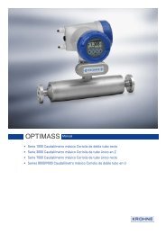
OPTIFLUX 2070
OPTIFLUX 2070
OPTIFLUX 2070

You also want an ePaper? Increase the reach of your titles
YUMPU automatically turns print PDFs into web optimized ePapers that Google loves.
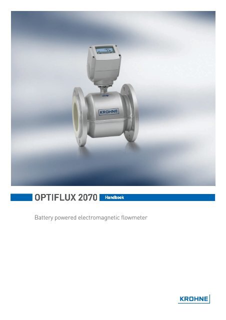
<strong>OPTIFLUX</strong> <strong>2070</strong><br />
Handbook<br />
Battery powered electromagnetic flowmeter
CONTENTS<br />
<strong>OPTIFLUX</strong> <strong>2070</strong><br />
1 Safety instructions......................................................................... 4<br />
1.1 Intended use......................................................................................................... 4<br />
1.2 Safety instructions from the manufacturer......................................................... 4<br />
1.2.1 Disclaimer.................................................................................................................. 4<br />
1.2.2 Information concerning the documentation ............................................................. 4<br />
1.2.3 Display conventions ................................................................................................... 5<br />
1.3 Safety instructions for the operator .................................................................... 5<br />
1.3.1 Transportation, handling and using instruction for batteries .................................. 6<br />
2 Instrument description.................................................................. 7<br />
2.1 Scope of delivery .................................................................................................. 7<br />
2.2 Instrument description ........................................................................................ 7<br />
2.3 Nameplate............................................................................................................ 8<br />
3 Installation..................................................................................... 9<br />
3.1 Pre-installation requirements............................................................................. 9<br />
3.2 General installation notes.................................................................................... 9<br />
3.3 Storage ................................................................................................................. 9<br />
3.4 Transport.............................................................................................................. 9<br />
3.5 Installation requirements .................................................................................. 10<br />
3.5.1 Inlet and outlet......................................................................................................... 10<br />
3.5.2 Mounting position and flange deviation .................................................................. 10<br />
3.5.3 Vibration................................................................................................................... 11<br />
3.5.4 Magnetic field .......................................................................................................... 11<br />
3.5.5 Bends ....................................................................................................................... 11<br />
3.5.6 Open discharge........................................................................................................ 12<br />
3.5.7 T-section ..................................................................................................................12<br />
3.5.8 Control valve ............................................................................................................ 13<br />
3.5.9 Pump........................................................................................................................ 13<br />
3.5.10 Grounding ................................................................................................................ 14<br />
3.6 Installation ......................................................................................................... 14<br />
3.7 Mounting of converter........................................................................................ 16<br />
3.7.1 Mounting of IFC 070 F.............................................................................................. 16<br />
4 Electrical connections ................................................................. 17<br />
4.1 Safety instructions ............................................................................................. 17<br />
4.2 Terminal assignment of IFC 070........................................................................ 17<br />
4.3 Signal cable........................................................................................................ 18<br />
4.4 Cable connection for field version ..................................................................... 19<br />
4.4.1 Flow sensor side...................................................................................................... 19<br />
4.4.2 Converter side ......................................................................................................... 20<br />
5 Start-up ....................................................................................... 21<br />
5.1 Connection of battery......................................................................................... 21<br />
2 www.krohne.com 04/2008 • 4000243601
<strong>OPTIFLUX</strong> <strong>2070</strong><br />
CONTENTS<br />
5.1.1 Internal battery ........................................................................................................ 21<br />
6 Operation ..................................................................................... 22<br />
6.1 Display and operating elements........................................................................ 22<br />
6.2 Menu of IFC 070 converter................................................................................. 22<br />
7 Service......................................................................................... 26<br />
7.1 Replacement of battery...................................................................................... 26<br />
8 Technical data ............................................................................. 28<br />
8.1 Technical data .................................................................................................... 28<br />
8.2 Dimensions and Weights ................................................................................... 33<br />
9 KROHNE Product Overview ......................................................... 36<br />
04/2008 • 4000243601<br />
www.krohne.com<br />
3
1 SAFETY INSTRUCTIONS<br />
<strong>OPTIFLUX</strong> <strong>2070</strong><br />
1.1 Intended use<br />
The electromagnetic flowmeter <strong>OPTIFLUX</strong> <strong>2070</strong> has been designed for measuring potable water<br />
and water with suspended particles.<br />
The <strong>OPTIFLUX</strong> <strong>2070</strong> features not only accurate flow measurement, but also continuous<br />
diagnostics in accordance with applicable standards. This self-diagnosis monitors and<br />
automatically reports improper functioning of the electronics, or faulty sensor electrodes. It<br />
reports battery charge condition and even provides a cable-break alarm.<br />
1.2 Safety instructions from the manufacturer<br />
1.2.1 Disclaimer<br />
The manufacturer will not be liable for any damage of any kind by using its product, including,<br />
but not limited to direct, indirect, incidental, punitive and consequential damages.<br />
This disclaimer does not apply in case the manufacturer has acted on purpose or with gross<br />
negligence. In the event any applicable law does not allow such limitations on implied warranties<br />
or the exclusion of limitation of certain damages, you may, if such law applies to you, not be<br />
subject to some or all of the above disclaimer, exclusions or limitations.<br />
Any product purchased from the manufacturer is warranted in accordance with the relevant<br />
product documentation and our Terms and Conditions of Sale.<br />
The manufacturer reserves the right to alter the content of its documents, including this<br />
disclaimer in any way, at any time, for any reason, without prior notification, and will not be liable<br />
in any way for possible consequences of such changes.<br />
1.2.2 Information concerning the documentation<br />
To prevent any injury to the user or damage to the device it is essential that you read the<br />
information in this document and observe applicable national standards, safety requirements<br />
and accident prevention regulations.<br />
If this document is not in your native language and if you have any problems understanding the<br />
text, we advise you to contact your local the manufacturer office for assistance. The<br />
manufacturer can not accept responsibility for any damage or injury caused by<br />
misunderstanding of the information in this document.<br />
This document is provided to help you establish operating conditions, which will permit safe and<br />
efficient use of this device. Special considerations and precautions are also described in the<br />
document, which appear in the form of underneath icons.<br />
4<br />
www.krohne.com 04/2008 • 4000243601
<strong>OPTIFLUX</strong> <strong>2070</strong><br />
SAFETY INSTRUCTIONS 1<br />
1.2.3 Display conventions<br />
The following symbols are used to help you navigate this documentation more easily:<br />
WARNING!<br />
These warning signs must be observed without fail. Even only partial disregarding such<br />
warnings can result in serious health damage, damage to the device itself or to parts of the<br />
operator’s plant.<br />
DANGER!<br />
This symbol designates safety advice on handling electricity.<br />
CAUTION!<br />
These warnings must be observed without fail. Even only partial disregarding such warnings can<br />
lead to improper functioning of the device.<br />
LEGAL NOTICE!<br />
This symbol designates information on statutory directives and standards.<br />
NOTE!<br />
This symbol designates important information for the handling of the device.<br />
• HANDLING<br />
This symbol designates all instructions for actions to be carried out by the operator in the<br />
specified sequence.<br />
i<br />
CONSEQUENCE<br />
This symbol designates all important consequences of the previous actions.<br />
1.3 Safety instructions for the operator<br />
WARNING!<br />
In general, devices from the manufacturer may only be installed, commissioned, operated and<br />
maintained by properly trained and authorized personnel.<br />
This document is provided to help you establish operating conditions, which will permit safe and<br />
efficient use of this device.<br />
04/2008 • 4000243601<br />
www.krohne.com<br />
5
1 SAFETY INSTRUCTIONS<br />
<strong>OPTIFLUX</strong> <strong>2070</strong><br />
1.3.1 Transportation, handling and using instruction for batteries<br />
WARNING!<br />
The used Lithium batteries are primary power sources with high energy content. If mistreated,<br />
they may present a potential risk.<br />
NOTE!<br />
KROHNE assumes no liability for customer failure.<br />
Please observe the following transportation, handling and using instructions:<br />
• Transport only in special packaging with special labels and transportation documents.<br />
• Do not short-circuit, recharge, overcharge or connect with false polarity.<br />
• Do not expose to temperature beyond the specified temperature range or incinerate the<br />
battery.<br />
• Do not crush, puncture or open cells or disassemble battery packs.<br />
• Do not weld or solder to the body of the battery.<br />
• Do not expose contents of battery to water.<br />
• Remove the battery from device before returning to KROHNE for service or warranty reasons.<br />
• Dispose battery packs in accordance with local regulations; where possible, recycle used<br />
batteries (see Chapter "Disposal" for futher information).<br />
6<br />
www.krohne.com 04/2008 • 4000243601
<strong>OPTIFLUX</strong> <strong>2070</strong><br />
INSTRUMENT DESCRIPTION 2<br />
2.1 Scope of delivery<br />
• Check the packing list to check if you received all that you ordered.<br />
• Inspect the cartons carefully for damage or signs of rough handling. Report damage to the<br />
carrier and to your local KROHNE office.<br />
Figure 2-1: Scope of delivery<br />
1 <strong>OPTIFLUX</strong> <strong>2070</strong> with blue protection cap<br />
2 Quick Start<br />
3 Factory calibration report<br />
4 CD-ROM including Handbook, Quick Start, Technical datasheet<br />
5 Grounding ring (optional)<br />
6 Cable (remote version only)<br />
2.2 Instrument description<br />
Two versions are available. You received a compact version or a remote version.<br />
1 2<br />
Figure 2-2: Versions<br />
1 compact version<br />
2 remote version<br />
04/2008 • 4000243601<br />
www.krohne.com<br />
7
2 INSTRUMENT DESCRIPTION<br />
<strong>OPTIFLUX</strong> <strong>2070</strong><br />
2.3 Nameplate<br />
Figure 2-3: Nameplate <strong>OPTIFLUX</strong> <strong>2070</strong><br />
1 Manufacturer<br />
2 Voltage information<br />
3 Material of wetted parts<br />
4 Meter constant<br />
5 Serial number<br />
6 Device type<br />
CAUTION!<br />
Check on the device nameplate. that the device is according to your order.<br />
8<br />
www.krohne.com 04/2008 • 4000243601
GK070: 10.234<br />
<strong>OPTIFLUX</strong> <strong>2070</strong><br />
INSTALLATION 3<br />
3.1 Pre-installation requirements<br />
Make sure that you have all necessary tools available:<br />
• Allen key (4 mm)<br />
• Philips screwdriver<br />
• Wrench for cable glands<br />
• Wrench for wall mounting bracket (remote version only)<br />
• Torque wrench for installing flowmeter in pipeline<br />
3.2 General installation notes<br />
Figure 3-1: Visual check<br />
3.3 Storage<br />
• Store the flowmeter in its original packing<br />
• storage temperature: -40 ... +65 °C<br />
3.4 Transport<br />
Figure 3-2: Transport<br />
04/2008 • 4000243601<br />
www.krohne.com<br />
9
3 INSTALLATION<br />
<strong>OPTIFLUX</strong> <strong>2070</strong><br />
3.5 Installation requirements<br />
3.5.1 Inlet and outlet<br />
Figure 3-3: Recommended inlet and outlet<br />
1 ≥ 5 DN<br />
2 ≥ 2 DN<br />
3.5.2 Mounting position and flange deviation<br />
Figure 3-4: Mounting position and flange deviation<br />
1 L max<br />
2 L min<br />
• Mount flowmeter either with converter aligned upwards or downwards.<br />
• Install flowmeter in line with the pipe axis.<br />
• Pipe flange faces must be parallel to each other.<br />
10<br />
www.krohne.com 04/2008 • 4000243601
<strong>OPTIFLUX</strong> <strong>2070</strong><br />
INSTALLATION 3<br />
CAUTION!<br />
Max. permissible deviation of pipe flange faces: L max - L min ≤ 0.5 mm<br />
3.5.3 Vibration<br />
Figure 3-5: Vibration<br />
3.5.4 Magnetic field<br />
Figure 3-6: Magnetic field<br />
3.5.5 Bends<br />
Figure 3-7: Installation in bending pipes<br />
04/2008 • 4000243601<br />
www.krohne.com<br />
11
3 INSTALLATION<br />
<strong>OPTIFLUX</strong> <strong>2070</strong><br />
3.5.6 Open discharge<br />
Install meter on a lowered section of the pipe to ensure a full pipe condition through the meter.<br />
Figure 3-8: Preferable installation close to open discharge<br />
3.5.7 T-section<br />
Figure 3-9: Recommended inlet for T-section installation<br />
1 ≥ 10 DN<br />
12<br />
www.krohne.com 04/2008 • 4000243601
<strong>OPTIFLUX</strong> <strong>2070</strong><br />
INSTALLATION 3<br />
3.5.8 Control valve<br />
Always install control valves downstream of flowmeter in order to avoid cavitation or distortion<br />
of flow profile.<br />
Figure 3-10: Position of control valve<br />
3.5.9 Pump<br />
Never install flowmeter at a pump suction side in order to avoid cavitation or flashing into the<br />
flowmeter.<br />
Figure 3-11: Preferable position of pump<br />
04/2008 • 4000243601<br />
www.krohne.com<br />
13
3 INSTALLATION<br />
<strong>OPTIFLUX</strong> <strong>2070</strong><br />
3.5.10 Grounding<br />
Figure 3-12: The grounding of the flowmeter<br />
1 Metal pipelines, not internally coated. Grounding without grounding rings!<br />
2 Metal pipelines with internal coating and non-conductive pipelines. Grounding with grounding rings!<br />
3 Grounding rings<br />
CAUTION!<br />
The grounding of the flowmeter provides a stable and accurate measurement.<br />
3.6 Installation<br />
Here you find the maximum pressure and torques for the flowmeter. All values are theoretical<br />
and calculated for optimum conditions and use with carbon steel flanges.<br />
Nominal size<br />
DN [mm]<br />
Pressure<br />
rating<br />
Bolts<br />
Polypropylene<br />
Max. torque [Nm]<br />
Hardrubber<br />
50 PN 40 4 × M 16 55 31<br />
65 PN 16 4 x M 16 51 42<br />
80 PN 40 8 × M 16 47 25<br />
100 PN 16 8 × M 16 39 30<br />
125 PN 16 8 x M 16 53 40<br />
150 PN 16 8 × M 20 68 47<br />
200 PN 10 8 × M 20 - 68<br />
250 PN 10 12 x M 20 - 65<br />
300 PN 10 12 x M 20 - 76<br />
350 PN 10 16 x M 20 - 75<br />
400 PN 10 16 x M 24 - 104<br />
450 PN 10 20 x M 24 - 93<br />
500 PN 10 20 x M 24 - 107<br />
600 PN 10 20 x M 27 - 138<br />
14<br />
www.krohne.com 04/2008 • 4000243601
<strong>OPTIFLUX</strong> <strong>2070</strong><br />
INSTALLATION 3<br />
Nominal size<br />
[inch]<br />
Flange class<br />
[lbs]<br />
Bolts<br />
Polypropylene<br />
Max. torque [Nm]<br />
Hardrubber<br />
2 150 4 × 5/8" 24 23<br />
3 150 4 × 5/8" 43 39<br />
4 150 8 × 5/8" 34 31<br />
5 150 8 × 3/4" 48 43<br />
6 150 8 × 3/4" 61 51<br />
8 150 8 × 3/4" - 69<br />
10 150 12 x 7/8" - 79<br />
12 150 12 x 7/8" - 104<br />
14 150 12 x 1" - 93<br />
16 150 16 x 1" - 91<br />
18 150 16 x 1 1/8" - 143<br />
20 150 20 x 1 1/8" - 127<br />
24 150 20 x 1 1/4" - 180<br />
Procedure to setup max. torque:<br />
• Step 1: approx. 50% of max. torque<br />
• Step 2: approx. 80% of max. torque<br />
• Step 3: 100% of max. torque given in tables before<br />
Figure 3-13: Maximum torque<br />
04/2008 • 4000243601<br />
www.krohne.com<br />
15
3 INSTALLATION<br />
<strong>OPTIFLUX</strong> <strong>2070</strong><br />
3.7 Mounting of converter<br />
NOTE!<br />
Only applicable for remote versions<br />
3.7.1 Mounting of IFC 070 F<br />
• Mount IFC 070 F with mounting plate on wall or standpipe.<br />
• Keep distance between sensor and signal converter as short as possible.<br />
• Observe length of the delivered signal cable.<br />
16<br />
www.krohne.com 04/2008 • 4000243601
<strong>OPTIFLUX</strong> <strong>2070</strong><br />
ELECTRICAL CONNECTIONS 4<br />
4.1 Safety instructions<br />
WARNING!<br />
Observe the regional occupational health and safety regulations without fail. Only work on the<br />
device electrics if you are appropriately trained.<br />
DANGER!<br />
Observe national installation regulations!<br />
4.2 Terminal assignment of IFC 070<br />
Figure 4-1: Removing side cap<br />
04/2008 • 4000243601<br />
www.krohne.com<br />
17
4 ELECTRICAL CONNECTIONS<br />
<strong>OPTIFLUX</strong> <strong>2070</strong><br />
Figure 4-2: Terminal assignment<br />
1 Status output 1<br />
2 Status output 2<br />
3 Not connected<br />
4 Ground<br />
5 Pulse output A<br />
6 Pulse output B<br />
Electrical values<br />
• Pulse output passive:<br />
f ≤ 500 Hz; I ≤ 10 mA; U: 5...24 VDC (P ≤ 100 mW)<br />
• Status output passive:<br />
I ≤ 10 mA; U: 5...24 VDC (P ≤ 100 mW)<br />
4.3 Signal cable<br />
CAUTION!<br />
Always use the supplied KROHNE signal cable.<br />
NOTE!<br />
You only receive a signal cable if you ordered a remote version.<br />
18<br />
www.krohne.com 04/2008 • 4000243601
<strong>OPTIFLUX</strong> <strong>2070</strong><br />
ELECTRICAL CONNECTIONS 4<br />
4.4 Cable connection for field version<br />
4.4.1 Flow sensor side<br />
Figure 4-3: Cable connection at flow sensor side<br />
1 cable length: 13 cm / 5"<br />
2 cable length: 5 cm / 2"<br />
3 cable length: 8 cm / 3"<br />
4 brown + white cable, used for field current<br />
5 purple + blue cable, used for electrode signals<br />
6 shield (terminal 1 of connector X2 + U-clamp)<br />
• Prepare appropriate cable lengths (1...3).<br />
• Connect the shield to the U-clamp, the brown cable to terminal 7 and the white to terminal 8.<br />
• Connect the shield to terminal 1, the purple cable to terminal 2 and the blue to terminal 3.<br />
04/2008 • 4000243601<br />
www.krohne.com<br />
19
4 ELECTRICAL CONNECTIONS<br />
<strong>OPTIFLUX</strong> <strong>2070</strong><br />
4.4.2 Converter side<br />
Figure 4-4: Cable connection at converter side<br />
1 cable length: 16 cm / 6.3"<br />
2 cable length: 5 cm / 2"<br />
3 cable length: 10 cm / 4"<br />
4 brown + white cable, used for field current<br />
5 purple + blue cable, used for electrode signals<br />
6 shield (terminal 1 of connector X2 + U-clamp)<br />
• Prepare appropriate cable lengths (1...3).<br />
• Connect the shield to the U-clamp, the brown cable to terminal 7 and the white to terminal 8.<br />
• Connect the shield to terminal 1, the purple cable to terminal 2 and the blue to terminal 3.<br />
20<br />
www.krohne.com 04/2008 • 4000243601
<strong>OPTIFLUX</strong> <strong>2070</strong><br />
START-UP 5<br />
5.1 Connection of battery<br />
CAUTION!<br />
Please connect battery before first use.<br />
KROHNE delivers each IFC 070 converter with a disconnected battery.<br />
5.1.1 Internal battery<br />
Figure 5-1: Connecting battery<br />
• remove the blue protection cap<br />
• remove the 4 Allen keys (4 mm)<br />
• remove the cover<br />
• fasten the battery connector to the internal connector in the IFC 070 converter<br />
• check that the display lights up<br />
• replace the cover<br />
WARNING!<br />
Make sure that the battery cable is not jammed by the cover.<br />
• tighten the 4 Allen bolts<br />
• replace the blue protection cap<br />
04/2008 • 4000243601<br />
www.krohne.com<br />
21
6 OPERATION<br />
<strong>OPTIFLUX</strong> <strong>2070</strong><br />
6.1 Display and operating elements<br />
1 battery status<br />
2 optical key to navigate through the menu and to scroll through the measuring pages<br />
3 reset button (only accessible with removed cover)<br />
4 flow direction<br />
5 measured value and measuring unit<br />
6 optical key to navigate through the menu<br />
6.2 Menu of IFC 070 converter<br />
• to enter the menu, hold the and key for 5 seconds<br />
i the display flashes<br />
• press the key to enter the menu<br />
i you see the menu number at the left (12 at the beginning) and the value at the right side of<br />
the display<br />
• scroll through the available positions with the key to the position you want to change<br />
• press the key to enter the value<br />
i the value flashes<br />
• use the and key to change the value<br />
• hold the key for 3 seconds to confirm the new value<br />
• to leave the programming mode, hold the key for 3 seconds to store the new value(s). If you<br />
do not want to store the new values, do not touch any key for 60 seconds<br />
other functions:<br />
• display test: press key twice for 1 second<br />
• software version: press key for 1 second<br />
22<br />
www.krohne.com 04/2008 • 4000243601
<strong>OPTIFLUX</strong> <strong>2070</strong><br />
OPERATION 6<br />
CAUTION!<br />
Take care with changing menu number 13. If you set this to "1", the display locks. IF this<br />
happens:<br />
• Remove the blue protection cap<br />
• Remove the 4 Allen keys (4 mm)<br />
• Remove the cover<br />
• Press both keys together with the reset button for 6 seconds as shown in the graph below<br />
• Use a small screwdriver for the reset button<br />
• Display starts with the menu, beginning with menu no. 12<br />
• Go to menu no. 13 and change 1 into 0<br />
• Confirm this value<br />
Figure 6-1: Resetting the menu<br />
04/2008 • 4000243601<br />
www.krohne.com<br />
23
6 OPERATION<br />
<strong>OPTIFLUX</strong> <strong>2070</strong><br />
Software version 2.0.0<br />
Menu<br />
No.<br />
Description<br />
Display<br />
default Selection list Remarks<br />
12 Measuring unit x 0 = m3, 1 = USG Customer defined<br />
13 Fiscal metering 0 0 = No, 1 = Yes Blocks menu<br />
21 Meter size xxx Defined at factory callibration -<br />
22 Meter constant xx.xxx Defined at factory callibration -<br />
23 Zero offset<br />
calibration<br />
0 Set to 1 In situ determination of zero<br />
point.<br />
Confirm with “>” for 3 seconds After countdown meter switches<br />
to measuring mode.<br />
Menu no. 24 is automatically set<br />
to 1.<br />
24 Zero selection 0 0 = factory calibration Selection which zero point to use<br />
1 = measured<br />
25 Flow direction 0 0 = Forward, 1 = Reverse -<br />
26 Measuring rate 10 1, 5, 10, 15, 20 seconds Measurement interval in seconds<br />
27 Low flow cut off 20 0, 5, 10, 20 mm/s Below value no measurement<br />
28 Time constant<br />
flow reading<br />
2 1 = fast, 2 = normal, 3 = slow Timeconstant of display<br />
29 Factory<br />
calibration /<br />
comm. mode<br />
0 0 = No, 1 = Yes For factory use only, blocks<br />
menu<br />
30 Self check 0 0 = off, 1 = on -<br />
32 Simulate 0 0 = off, 1 = On 1 puls / second (for cable testing)<br />
outputs<br />
41 Output A 0 0 = off, 1 = on -<br />
(pulse)<br />
42 Output B 0 0 = off, 1 = on -<br />
(pulse)<br />
43 Phase shift<br />
pulse output<br />
90 90, 180 degrees offset or<br />
F - r ( A-forward, B-reverse flow)<br />
44 Pulse width 1 1, 5, 10, 50, 100 ms -<br />
45 Pulse value xx.xxx in m3 / pulse or USG / pulse -<br />
51 Status output 1<br />
Self checking<br />
0 0 = off, 1 = on Active at instrument failure<br />
52 Status output 1<br />
Battery pre<br />
warning<br />
53 Status output 1<br />
Battery final<br />
warning<br />
54 Status output 1<br />
Counter<br />
overrun<br />
55 Status output 2<br />
Self checking<br />
0 0 = off, 1 = on Active 1 year before empty<br />
battery<br />
0 0 = off, 1 = on Active at low battery<br />
0 0 = off, 1 = on After 99999999 counter starts at<br />
zero<br />
0 0 = off, 1 = on Active at instrument failure<br />
24<br />
www.krohne.com 04/2008 • 4000243601
<strong>OPTIFLUX</strong> <strong>2070</strong><br />
OPERATION 6<br />
Software version 2.0.0<br />
Menu<br />
No.<br />
Description<br />
56 Status output 2<br />
Battery pre<br />
warning<br />
57 Status output 2<br />
Battery final<br />
warning<br />
58 Status output 2<br />
Counter<br />
overrun<br />
59 Status outputs<br />
pulsating<br />
60 Show Flow<br />
Rate<br />
61 Show Counter<br />
Forward<br />
63 Show Counter<br />
Reverse<br />
65 Show Net<br />
Counter<br />
66 All counters<br />
reset<br />
71 Counters<br />
Run/Stop<br />
72 All Errors<br />
Reset<br />
0 0 = off, 1 = on Active 1 year before empty<br />
battery<br />
0 0 = off, 1 = on Active at low battery<br />
0 0 = off, 1 = on After 99999999 counter starts at<br />
zero<br />
1 0 = off, 1 = on Pulse of 1 ms every second<br />
0 0 = off, 1 = on -<br />
0 0 = off, 1 = on -<br />
0 0 = off, 1 = on -<br />
1 0 = off, 1 = on -<br />
88888 Set to 00000 After reset display value is back<br />
to 88888<br />
Confirm with “>” for 3 seconds<br />
1 0 = stop, 1 = run<br />
0 Set to 1 After reset display value is back<br />
to 0<br />
Confirm with “>” for 3 seconds<br />
73 Battery type 1 1 = single, 2 = dual, 2 = external External battery is in preparation<br />
74 Battery pack xx Value in Ah -<br />
capacity<br />
75 Reset battery<br />
life time<br />
counter<br />
76 Load default<br />
settings<br />
77 Fiscal metering<br />
verification<br />
reading<br />
Display<br />
default Selection list Remarks<br />
0 Set to 1 After reset display value is back<br />
to 0<br />
Confirm with “>” for 3 seconds<br />
0 Set to 1 After reset display value is back<br />
to 0<br />
Confirm with “>” for 3 seconds<br />
0 0 = off, 1 = on For legal verification only<br />
04/2008 • 4000243601<br />
www.krohne.com<br />
25
7 SERVICE<br />
<strong>OPTIFLUX</strong> <strong>2070</strong><br />
7.1 Replacement of battery<br />
Figure 7-1: Removing battery<br />
• Remove the blue protection cap.<br />
• Remove the 4 Allen keys (4 mm).<br />
• Remove the cover.<br />
• Disconnect the connector of the battery.<br />
• Remove the battery holder by pulling it upwards.<br />
Figure 7-2: Connecting battery<br />
• Remove the battery from the holder.<br />
• Insert the new battery in the holder.<br />
• Replace the holder.<br />
• Fasten the battery connector to the internal connector in the IFC 070 converter.<br />
• Check that the display lights up.<br />
26<br />
www.krohne.com 04/2008 • 4000243601
<strong>OPTIFLUX</strong> <strong>2070</strong><br />
SERVICE 7<br />
• Replace the cover.<br />
WARNING!<br />
Make sure that the battery cable is not jammed by the cover.<br />
• Tighten the 4 bolts.<br />
• Enter the programming mode, hold the and key for 5 seconds.<br />
i The display flashes.<br />
• Press the key to enter the menu.<br />
• Scroll through the available positions with the key to position 74 and check the battery<br />
capacity (important for battery life indication).<br />
• Go to position 75 and enter "1" (reset battery counter).<br />
i Battery capacity symbol at the display should be "full".<br />
• Hold the key for 3 seconds to confirm the new value and go back to the measuring mode.<br />
• Replace the blue protection cap.<br />
04/2008 • 4000243601<br />
www.krohne.com<br />
27
8 TECHNICAL DATA<br />
<strong>OPTIFLUX</strong> <strong>2070</strong><br />
8.1 Technical data<br />
<strong>OPTIFLUX</strong> <strong>2070</strong> flowmeter<br />
Versions<br />
Compact<br />
Field<br />
Performance<br />
Measurement functionality<br />
<strong>OPTIFLUX</strong> <strong>2070</strong> C: IFC 070 C converter on top of<br />
<strong>OPTIFLUX</strong> 2000 flow sensor<br />
<strong>OPTIFLUX</strong> <strong>2070</strong> F: IFC 070 F converter separate from<br />
<strong>OPTIFLUX</strong> 2000 flow sensor<br />
Default: totalised volume<br />
Selectable: actual volume flowrate, + counter totaliser,<br />
- counter totaliser<br />
Measuring range 0…12m/s (0…39ft/s)<br />
Max. deviation (under reference conditions) 1<br />
Repeatibility<br />
Process conditions<br />
1 See graph.<br />
±0.5% of measured flowrate value ± 2mm/s<br />
±0.3% (v > 0.5 m/s / 1.5 ft/s)<br />
Potable water<br />
Surface water / clean ground water<br />
Nominal diameter VN14 VN15<br />
ASME [inch]<br />
2"<br />
2 1/2"<br />
3"<br />
4"<br />
5"<br />
6"<br />
8"<br />
10"<br />
12"<br />
14"<br />
16"<br />
18"<br />
20"<br />
24"<br />
DN [mm]<br />
50<br />
65<br />
80<br />
100<br />
125<br />
150<br />
200<br />
250<br />
300<br />
350<br />
400<br />
450<br />
500<br />
600<br />
Nominal flange pressure<br />
EN 1092-1 - PN 40<br />
EN 1092-1 - PN 25<br />
EN 1092-1 - PN 16<br />
EN 1092-1 - PN 10<br />
EN 1092-1 - PN 6<br />
ISO insertion length<br />
ASME B16.5 - 150 lbs RF<br />
ASME B16.5 - 300 lbs RF<br />
ASME B16.5 - 600 lbs RF<br />
ASME B16.5 - 900 lbs RF<br />
ASME B16.5 - 1500 lbs RF<br />
AWWA - class B or D FF<br />
JIS 10 K<br />
JIS 20 K<br />
28<br />
www.krohne.com 04/2008 • 4000243601
<strong>OPTIFLUX</strong> <strong>2070</strong><br />
TECHNICAL DATA 8<br />
Nominal diameter VN14 VN15<br />
ASME [inch]<br />
2"<br />
2 1/2"<br />
3"<br />
4"<br />
5"<br />
6"<br />
8"<br />
10"<br />
12"<br />
14"<br />
16"<br />
18"<br />
20"<br />
24"<br />
DN [mm]<br />
50<br />
65<br />
80<br />
100<br />
125<br />
150<br />
200<br />
250<br />
300<br />
350<br />
400<br />
450<br />
500<br />
600<br />
Liner<br />
Polypropylene<br />
Hardrubber<br />
See pressure and temperature limits for various liners<br />
Electrodes<br />
Hastelloy C4<br />
Stainless steel 1,4571 (AISI 316 Ti)<br />
Titanium<br />
Grounding rings<br />
Hastelloy C4<br />
Stainless steel 1,4571 (AISI 316 Ti)<br />
Titanium<br />
Flanges<br />
Steel 1.0460 (C 22,8 )<br />
Steel 1.0038 ( RSt37-2)<br />
Stainless steel 1.4404 (AISI 316 L)<br />
Stainless steel 1.4571 (AISI 316 Ti)<br />
Materials<br />
Measuring tube - austenitic stainless<br />
steel<br />
Housing (polyurethane coated) sheet<br />
steel<br />
Housing stainless steel<br />
Die-cast aluminium connection box<br />
(polyurethane coated)<br />
Stainless steel connection box<br />
Other materials on request<br />
Protection category<br />
IP 66 / 67 eq. NEMA 4/4X / 6<br />
IP 68 eq. NEMA 6P<br />
04/2008 • 4000243601<br />
www.krohne.com<br />
29
8 TECHNICAL DATA<br />
<strong>OPTIFLUX</strong> <strong>2070</strong><br />
Nominal diameter VN14 VN15<br />
ASME [inch]<br />
2"<br />
2 1/2"<br />
3"<br />
4"<br />
5"<br />
6"<br />
8"<br />
10"<br />
12"<br />
14"<br />
16"<br />
18"<br />
20"<br />
24"<br />
DN [mm]<br />
50<br />
65<br />
80<br />
100<br />
125<br />
150<br />
200<br />
250<br />
300<br />
350<br />
400<br />
450<br />
500<br />
600<br />
Versions<br />
Compact<br />
Separate<br />
Electrical conductivity<br />
Min. conductivity<br />
50 µS/cm<br />
J standard J optional U on request<br />
Maximum deviation Y [%] vs flow velocity X [m/s]<br />
1 <strong>OPTIFLUX</strong> <strong>2070</strong><br />
30<br />
www.krohne.com 04/2008 • 4000243601
<strong>OPTIFLUX</strong> <strong>2070</strong><br />
TECHNICAL DATA 8<br />
IFC 070 flow converter<br />
Functions<br />
Flow direction<br />
Low flow cut-off<br />
Design<br />
Display<br />
Units<br />
Bi-directional measurement<br />
Selectable<br />
8 digits LCD<br />
Status indication for battery, diagnostics<br />
m 3 , US Gallons<br />
m 3 /h, USGPM<br />
Cable connections<br />
Standard 2x M20 x 1,5<br />
Optional 1/2" NPT, PF 1/2<br />
Materials<br />
Converter housing<br />
In- and output<br />
Outputs<br />
Die-cast aluminium (polyurethane coated)<br />
2 passive pulse outputs for remote totalising<br />
f ≤ 500 Hz; I ≤ 10 mA; U: 5...24 VDC (P ≤ 100 mW)<br />
2 passive status outputs<br />
I ≤ 10 mA; U: 5...24 VDC (P ≤ 100 mW)<br />
Power supply<br />
Standard<br />
Alarms<br />
Battery replacement<br />
Approvals<br />
Protection class<br />
2 lithium batteries (D-cell), typical lifetime 6 years.<br />
Pre-alarm 1 year before battery depletion and final alarm<br />
Possible without loss of totaliser data<br />
IP 66/67 (NEMA 4X/6)<br />
04/2008 • 4000243601<br />
www.krohne.com<br />
31
8 TECHNICAL DATA<br />
<strong>OPTIFLUX</strong> <strong>2070</strong><br />
Temperature range<br />
Process [°C]<br />
Ambient [°C]<br />
min. max. min. max.<br />
Hardrubber<br />
Separate flow sensor (<strong>OPTIFLUX</strong><br />
2000 F)<br />
Compact with IFC 070 (<strong>OPTIFLUX</strong><br />
<strong>2070</strong> C)<br />
Polypropylene 1<br />
Separate flow sensor (<strong>OPTIFLUX</strong><br />
2000 F)<br />
Compact with IFC 070 (<strong>OPTIFLUX</strong><br />
<strong>2070</strong> C)<br />
1 Polypropylene available for DN 50 - 150<br />
-5 80 -40 65<br />
-5 80 -40 65<br />
-5 90 -40 65<br />
-5 90 -40 65<br />
Process [°F]<br />
Ambient [°F]<br />
min. max. min. max.<br />
Hardrubber<br />
Separate flow sensor (<strong>OPTIFLUX</strong><br />
2000 F)<br />
Compact with IFC 070 (<strong>OPTIFLUX</strong><br />
<strong>2070</strong> C)<br />
Polypropylene 1<br />
Separate flow sensor (<strong>OPTIFLUX</strong><br />
2000 F)<br />
Compact with IFC 070 (<strong>OPTIFLUX</strong><br />
<strong>2070</strong> C)<br />
1 Polypropylene available for ASME 2" - 6"<br />
23 176 -40 149<br />
23 176 -40 149<br />
23 194 -40 149<br />
23 194 -40 149<br />
32<br />
www.krohne.com 04/2008 • 4000243601
<strong>OPTIFLUX</strong> <strong>2070</strong><br />
TECHNICAL DATA 8<br />
8.2 Dimensions and Weights<br />
<strong>OPTIFLUX</strong> <strong>2070</strong> C<br />
T<br />
070<br />
H<br />
W<br />
<strong>OPTIFLUX</strong> 2000 F<br />
c<br />
a<br />
T box<br />
W<br />
IFC 070 F<br />
335mm<br />
310mm<br />
175mm<br />
04/2008 • 4000243601<br />
www.krohne.com<br />
33
8 TECHNICAL DATA<br />
<strong>OPTIFLUX</strong> <strong>2070</strong><br />
Dimensions and weights in mm and kg<br />
Flanges acc. EN 1092-1 Dimensions [mm] Approx.<br />
weight [kg]<br />
DN PN L H W T box T 070<br />
50 40 200 186 165 264 356 13<br />
65 16 200 200 185 278 370 11<br />
80 16 200 209 200 287 379 17<br />
100 16 250 237 220 315 407 17<br />
125 16 250 266 250 344 436 21<br />
150 16 300 300 285 378 470 29<br />
200 10 350 361 340 439 531 36<br />
250 10 400 408 395 486 578 50<br />
300 10 500 458 445 536 628 60<br />
350 10 500 510 505 588 680 80<br />
400 10 600 568 565 646 738 103<br />
450 10 600 618 615 696 788 113<br />
500 10 600 671 670 749 841 132<br />
600 10 600 781 780 859 951 167<br />
Dimensions and weights in inch, psig and lbs<br />
Flanges acc. ASME B16.5 Dimensions for 150 lbs flanges [inch] Approx.<br />
weight [lbs]<br />
DN PN L H W T box T 070<br />
2 150 7,9 7,05 5,98 10,12 13,75 34<br />
3 150 7,9 8,03 7,5 11,10 14,73 42<br />
4 150 9,8 9,49 9,0 12,56 16,19 56<br />
5 150 9,84 10,55 10,00 13,62 17,25 65<br />
6 150 11,8 11,69 11,0 14,76 18,39 80<br />
8 150 13,8 14,25 13,5 17,32 20,95 100<br />
10 150 15,75 16,30 16,00 19,37 23,00 148<br />
12 150 19,69 18,78 19,00 21,85 25,48 212<br />
14 150 27,56 20,67 21,00 23,74 27,37 289<br />
16 150 31,50 22,95 23,50 26,02 29,65 369<br />
18 150 31,50 24,72 25,00 27,80 31,42 415<br />
20 150 31,50 26,97 27,50 30,04 33,67 497<br />
24 150 31,50 31,38 32,00 34,45 38,08 680<br />
34<br />
www.krohne.com 04/2008 • 4000243601
<strong>OPTIFLUX</strong> <strong>2070</strong><br />
TECHNICAL DATA 8<br />
Dimensions and weights in mm, bar and kg<br />
Flanges acc. ASME B<br />
16.5 Dimensions for 150 lbs flanges [mm]<br />
Approx.<br />
weight [kg]<br />
DN PN L H W T box T 070<br />
2 150 200 179 152 257 349 15<br />
3 150 200 204 190,5 282 374 19<br />
4 150 250 241 228,6 319 411 25<br />
5 150 250 268 254 346 438 29<br />
6 150 300 297 279,4 375 467 36<br />
8 150 350 362 342,9 440 532 45<br />
10 150 400 414 406,4 492 584 67<br />
12 150 500 477 482,6 555 647 96<br />
14 150 700 525 533,4 603 695 131<br />
16 150 800 583 596,9 661 753 167<br />
18 150 800 628 635,0 706 798 188<br />
20 150 800 685 698,5 763 855 225<br />
24 150 800 797 812,8 875 967 308<br />
04/2008 • 4000243601<br />
www.krohne.com<br />
35
<strong>OPTIFLUX</strong> <strong>2070</strong> nnnnnnnnnnnnnnnnnnnnnnnnnnnnnnnnnnnnnnnnnnnn<br />
KROHNE Product Overview<br />
• Electromagnetic flowmeters<br />
• Variable area flowmeters<br />
• Mass flowmeters<br />
• Ultrasonic flowmeters<br />
• Vortex flowmeters<br />
• Flow controllers<br />
• Level measuring instruments<br />
• Pressure gauges<br />
• Temperature measuring instruments<br />
• Water solutions & analysis<br />
• Oil and gas turnkey solutions<br />
Addresses:<br />
© KROHNE 04/2008 4000243601 Subject to change without notice<br />
Germany<br />
Northern sales office<br />
KROHNE Messtechnik GmbH & Co. KG<br />
Bremer Str. 133<br />
D-21073 Hamburg<br />
Phone:+49 (0)40 767 3340<br />
Fax:+49 (0)40 767 33412<br />
nord@krohne.de<br />
ZIP code: 10000 - 29999, 49000 - 49999<br />
Western and middle sales office<br />
KROHNE Messtechnik GmbH & Co. KG<br />
Ludwig-Krohne-Straße<br />
D-47058 Duisburg<br />
Phone:+49 (0)203 301 416<br />
Fax:+49 (0)203 301 10416<br />
west@krohne.de<br />
ZIP code: 30000 - 34999, 37000 -<br />
48000, 50000 - 53999, 57000 - 59999,<br />
98000 - 99999<br />
Southern sales office<br />
KROHNE Messtechnik GmbH & Co. KG<br />
Landsberger Str. 392<br />
D-81241 Munich<br />
Phone:+49 (0)89 121 5620<br />
Fax:+49 (0)89 129 6190<br />
sued@krohne.de<br />
ZIP code: 0 - 9999, 80000 - 89999,<br />
90000 - 97999<br />
Southwestern sales office<br />
KROHNE Messtechnik GmbH & Co. KG<br />
Rüdesheimer Str. 40<br />
D-65239 Hochheim/Main<br />
Phone: +49(0)6146) 827 30<br />
Fax:+49 (0)6146 827 312<br />
rhein-main@krohne.de<br />
ZIP code: 35000 - 36999, 54000 -<br />
56999, 60000 - 79999<br />
Instrumentation and control<br />
equipment catalog<br />
TABLAR Messtechnik GmbH<br />
Ludwig-Krohne-Straße 5<br />
D-47058 Duisburg<br />
Phone:+49 (0)2 03 305 880<br />
Fax:+49 (0)2 03 305 8888<br />
kontakt@tablar.de www.tablar.de<br />
KROHNE sales<br />
companies<br />
International<br />
Australia<br />
KROHNE Australia Pty Ltd<br />
Quantum Business Park 10/287<br />
Victoria Rd Rydalmere NSW 2116<br />
Phone: +61 2 8846 1700<br />
Fax: +61 2 8846 1755<br />
krohne@krohne.com.au<br />
Austria<br />
KROHNE Gesellschaft m.b.H.<br />
Modecenterstraße 14<br />
A-1030 Vienna<br />
Phone:+43 (0)1/203 45 32<br />
Fax:+43 (0)1/203 45 32 99<br />
info@krohne.at<br />
Belgium<br />
KROHNE Belgium N.V.<br />
Brusselstraat 320<br />
B-1702 Groot Bijgaarden<br />
Phone:+32 (0)2 4 66 00 10<br />
Fax:+32 (0)2 4 66 08 00<br />
krohne@krohne.be<br />
Brazil<br />
KROHNE Conaut Controles<br />
Automaticos Ltda.<br />
Estrada Das Águas Espraiadas, 230<br />
C.P. 56 06835 - 080 EMBU - SP<br />
Phone:+55 (0)11-4785-2700<br />
Fax:+55 (0)11 4785-2768<br />
conaut@conaut.com.br<br />
China<br />
KROHNE Measurement Instruments<br />
(Shanghai) Co. Ltd., (KMIC)<br />
Room 1501<br />
1033 Zhaojiabang Road<br />
Shanghai 200030<br />
Phone: +86 21 6487 9611<br />
Fax:+86 21 6438 7110<br />
info@krohne-asia.com<br />
Czech Republic<br />
Krohne CZ, spol. s r.o.<br />
Sobìsická 156<br />
63800 Brno<br />
Phone: +420 (0)545.242 627<br />
Fax: +420 (0)545 220 093<br />
brno@krohne.cz<br />
France<br />
KROHNE S.A.S.<br />
Les Ors BP 98<br />
F-26103 ROMANS Cedex<br />
Phone:+33 (0)4 75 05 44 00<br />
Fax:+33 (0)4 75 05 00 48<br />
info@krohne.fr<br />
Great Britain<br />
KROHNE Ltd.<br />
Rutherford Drive<br />
Park Farm Industrial Estate<br />
Wellingborough<br />
Northants NN8 6AE<br />
Phone:+44 (0)19 33 408 500<br />
Fax:+44 (0)19 33 408 501<br />
info@krohne.co.uk<br />
CIS<br />
Kanex KROHNE Engineering AG<br />
Business-Centre Planeta<br />
Office 404 ul.<br />
Marxistskaja 3<br />
109147 Moscow/Russia<br />
Phone:+7 (0)095 911 7165<br />
Fax:+7 (0)095 742 8873<br />
krohne@dol.ru<br />
India<br />
Krohne Marshall Ltd.<br />
A-34/35, M.I.D.C. Industrial Area,<br />
H-Block<br />
Pimpri Poona 411018<br />
Phone:+91 (0)202 744 2020<br />
Fax:+91 (0)202 744 2020<br />
pcu@vsnl.net<br />
Iran<br />
KROHNE Liaison Office<br />
North Sohrevardi Ave. 26,<br />
Sarmad St., Apt. #9<br />
Tehran 15539<br />
Phone: +9821 8874 5973<br />
Fax: +9821 8850 1268<br />
krohne@krohneiran.com<br />
Italy<br />
KROHNE Italia Srl.<br />
Via V. Monti 75<br />
I-20145 Milan<br />
Phone:+39 02 4300 661<br />
Fax:+39 02 4300 6666<br />
info@krohne.it<br />
Korea<br />
KROHNE Korea<br />
Room 508 Miwon Bldg 43<br />
Yoido-Dong Youngdeungpo-Ku<br />
Seoul, Korea<br />
Phone: 00-82-2-782-1900<br />
Fax: 00-82-2-780-1749<br />
mail@krohne.co.kr<br />
Netherlands<br />
KROHNE Nederland B.V.<br />
Kerkeplaat 14<br />
NL-3313 LC Dordrecht<br />
Phone:+31 (0)78 630 6200<br />
Fax:+31 (0)78 630 6405<br />
Service Direct: +31 (0)78 630 6222<br />
info@krohne.nl<br />
Norway<br />
KROHNE Norway A.S.<br />
Ekholtveien 114<br />
NO-1521 Moss<br />
Phone:+47 (0)69 264 860<br />
Fax:+47 (0)69 267 333<br />
postmaster@krohne.no<br />
Poland<br />
KROHNE Polska Sp.z.o.o.<br />
ul. Stary Rynek Oliwski 8a<br />
80-324 Gdansk<br />
Phone: +48 (0)58 520 9211<br />
Fax.:+48 (0)58 520 9212<br />
info@krohne.pl<br />
Switzerland<br />
KROHNE AG<br />
Uferstr. 90<br />
CH-4019 Basel<br />
Phone:+41 (0)61 638 30 30<br />
Fax:+41 (0)61 638 30 40<br />
info@krohne.ch<br />
Singapore<br />
Tokyo Keiso - KROHNE (Singapore)<br />
Pte. Ltd.<br />
14, International Business Park,<br />
Jurong East<br />
Chiyoda Building, #01-01/02<br />
Singapore 609922<br />
Phone: (65) 6567 4548<br />
Fax : (65) 6567 9874<br />
tks@tokyokeiso-krohne.com.sg<br />
Republic of South Africa<br />
KROHNE Pty. Ltd.<br />
Bushbock Close<br />
Corporate Park South<br />
Midrand, Gauteng<br />
P.O. Box 2069<br />
Midrand, 1685<br />
Tel.: +27 (0)11 314 1391<br />
Fax: +27 (0)11 314 1681<br />
midrand@krohne.co.za<br />
Spain<br />
I.I. KROHNE IBERIA, S.r.l.<br />
Poligono Industrial Nilo<br />
Calle Brasil, nº. 5<br />
28806 Alcalá de Henares Madrid<br />
Phone: +34 (0)91 883 2152<br />
Fax: +34 (0)91 883 4854<br />
krohne@krohne.es<br />
USA<br />
KROHNE, Inc.<br />
7 Dearborn Road<br />
Peabody, MA 01960<br />
Phone: +1 (800) FLOWING<br />
Phone: +1 (978) 535 6060 (in MA)<br />
info@krohne.com<br />
Representatives<br />
Algeria<br />
Argentina<br />
Cameroon<br />
Canada<br />
Chile<br />
Columbia<br />
Croatia<br />
Denmark<br />
Ecuador<br />
Egypt<br />
Finland<br />
Gabon<br />
Ghana<br />
Greece<br />
Hong Kong<br />
Hungary<br />
Indonesia<br />
Iran<br />
Ireland<br />
Israel<br />
Ivory Coast<br />
Japan<br />
Jordan<br />
Kuwait<br />
Libya<br />
Lithuania<br />
Malaysia<br />
Mauritius<br />
Mexico<br />
Morocco<br />
New Zealand<br />
Peru<br />
Portugal<br />
Romania<br />
Saudi Arabia<br />
Senegal<br />
Slovakia<br />
Slovenia<br />
Sweden<br />
Taiwan<br />
Thailand<br />
Tunisia<br />
Turkey<br />
Venezuela<br />
Yugoslavia<br />
Other countries<br />
KROHNE Messtechnik GmbH & Co. KG<br />
Ludwig-Krohne-Str. 5<br />
D-47058 Duisburg<br />
Phone:+49 (0)203 301 0<br />
Fax:+49 (0)203 301 389<br />
export@krohne.de<br />
www.krohne.com