OPTIFLUX 1000
OPTIFLUX 1000
OPTIFLUX 1000

You also want an ePaper? Increase the reach of your titles
YUMPU automatically turns print PDFs into web optimized ePapers that Google loves.
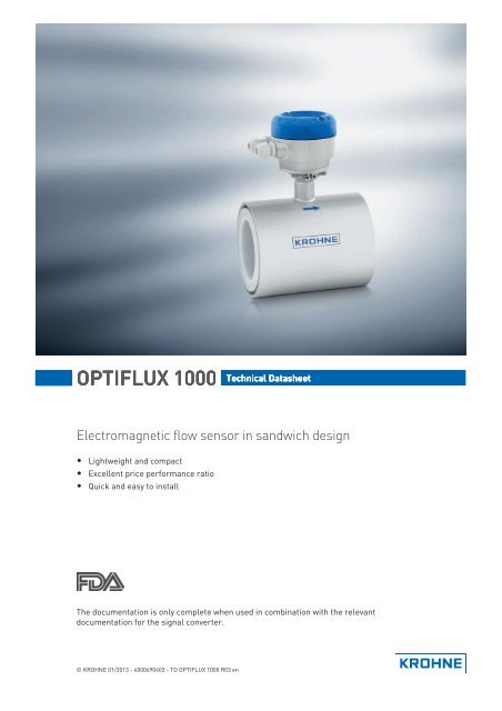
<strong>OPTIFLUX</strong> <strong>1000</strong> Technical Datasheet<br />
Electromagnetic flow sensor in sandwich design<br />
• Lightweight and compact<br />
• Excellent price performance ratio<br />
• Quick and easy to install<br />
The documentation is only complete when used in combination with the relevant<br />
documentation for the signal converter.<br />
© KROHNE 01/2013 - 4000690403 - TD <strong>OPTIFLUX</strong> <strong>1000</strong> R03 en
CONTENTS<br />
<strong>OPTIFLUX</strong> <strong>1000</strong><br />
1 Product features 3<br />
1.1 Cost efficient and reliable flow sensor ............................................................................ 3<br />
1.2 Options.............................................................................................................................. 5<br />
1.3 Measuring principle.......................................................................................................... 6<br />
2 Technical data 7<br />
2.1 Technical data................................................................................................................... 7<br />
2.2 Measuring accuracy ....................................................................................................... 11<br />
2.3 Dimensions and weights ................................................................................................ 12<br />
3 Installation 14<br />
3.1 Notes on installation ......................................................................................................14<br />
3.2 Intended use ................................................................................................................... 14<br />
3.3 Installation conditions ....................................................................................................14<br />
3.3.1 Vibration ................................................................................................................................ 14<br />
3.3.2 Magnetic field........................................................................................................................ 14<br />
3.3.3 Inlet and outlet ...................................................................................................................... 15<br />
3.3.4 Bends in 2 or 3 dimensions................................................................................................... 15<br />
3.3.5 T-section ............................................................................................................................... 15<br />
3.3.6 Bends .................................................................................................................................... 16<br />
3.3.7 Open discharge ..................................................................................................................... 16<br />
3.3.8 Flange deviation.................................................................................................................... 17<br />
3.3.9 Pump ..................................................................................................................................... 17<br />
3.3.10 Control valve ....................................................................................................................... 17<br />
3.3.11 Air venting and vacuum forces ...........................................................................................18<br />
3.3.12 Mounting position................................................................................................................ 19<br />
3.3.13 Temperatures ..................................................................................................................... 19<br />
4 Electrical connections 20<br />
4.1 Safety instructions.......................................................................................................... 20<br />
4.2 Grounding ....................................................................................................................... 20<br />
4.3 Virtual reference for IFC 300 (C, W and F version) ........................................................ 21<br />
5 Notes 22<br />
2 www.krohne.com 01/2013 - 4000690403 - TD <strong>OPTIFLUX</strong> <strong>1000</strong> R03 en
<strong>OPTIFLUX</strong> <strong>1000</strong><br />
PRODUCT FEATURES 1<br />
1.1 Cost efficient and reliable flow sensor<br />
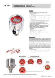
The flangeless <strong>OPTIFLUX</strong> <strong>1000</strong> electromagnetic flow sensor is compact and lightweight. The<br />
design is robust with the highly resistant, reinforced PFA liner and Hastelloy ® electrodes, which<br />
offers an excellent chemical resistance.<br />
The device is a cost-efficient and reliable solution for a wide range of applications. The best<br />
economical choice for industries varying from water and wastewater, agriculture, utilisation and<br />
from fire-fighting to machine building.<br />
1 Sandwich design<br />
2 PFA liner<br />
3 Hastelloy ® electrodes<br />
01/2013 - 4000690403 - TD <strong>OPTIFLUX</strong> <strong>1000</strong> R03 en<br />
www.krohne.com<br />
3
1 PRODUCT FEATURES<br />
<strong>OPTIFLUX</strong> <strong>1000</strong><br />
Highlights<br />
• Sandwich (wafer) design<br />
• Lightweight and compact for easy handling and space saving installation<br />
• Affordable price<br />
• Excellent chemical resistance<br />
• Bi-directional measurements<br />
• No pressure loss<br />
• Insensitive to vibrations<br />
• No internal moving parts, no maintenance<br />
Industries<br />
• Machine building<br />
• Energy, HVAC<br />
• Water & wastewater<br />
• Process industries<br />
Applications<br />
• Mixing, batching and dosing systems, filtration systems, pump control<br />
• Water flow monitoring<br />
• Water circulation and treatment systems<br />
• Fire-fighting systems, foam mixing, control of sprinkler systems<br />
• Heat transfer and cooling systems<br />
• Water including; raw water, process water, wastewater, salt water, hot and cold water<br />
• Mud, slurry, sludge, manure<br />
4<br />
www.krohne.com<br />
01/2013 - 4000690403 - TD <strong>OPTIFLUX</strong> <strong>1000</strong> R03 en
<strong>OPTIFLUX</strong> <strong>1000</strong><br />
PRODUCT FEATURES 1<br />
1.2 Options<br />
The <strong>OPTIFLUX</strong> <strong>1000</strong> flow sensor is available in a<br />
diameter range from DN10 up to DN150. The<br />
compact flangeless flow sensor meets all applicable<br />
process connections: EN 1092, DIN, ANSI and JIS.<br />
Signal converters<br />
The <strong>OPTIFLUX</strong> <strong>1000</strong> flow sensor is compatible with<br />
the IFC 050, IFC 100 and IFC 300 signal converter.<br />
The flangeless flowmeter is suitable for compact<br />
and remote (field) mounting.<br />
01/2013 - 4000690403 - TD <strong>OPTIFLUX</strong> <strong>1000</strong> R03 en<br />
www.krohne.com<br />
5
1 PRODUCT FEATURES<br />
<strong>OPTIFLUX</strong> <strong>1000</strong><br />
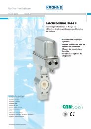
1.3 Measuring principle<br />
An electrically conductive fluid flows inside an electrically insulated pipe through a magnetic<br />
field. This magnetic field is generated by a current, flowing through a pair of field coils.<br />
Inside of the fluid, a voltage U is generated:<br />
U = v * k * B * D<br />
in which:<br />
v = mean flow velocity<br />
k = factor correcting for geometry<br />
B = magnetic field strength<br />
D = inner diameter of flow meter<br />
The signal voltage U is picked off by electrodes and is proportional to the mean flow velocity v<br />
and thus the flow rate q. A signal converter is used to amplify the signal voltage, filter it and<br />
convert it into signals for totalising, recording and output processing.<br />
1 Induced voltage (proportional to flow velocity)<br />
2 Electrodes<br />
3 Magnetic field<br />
4 Field coils<br />
6<br />
www.krohne.com<br />
01/2013 - 4000690403 - TD <strong>OPTIFLUX</strong> <strong>1000</strong> R03 en
<strong>OPTIFLUX</strong> <strong>1000</strong><br />
TECHNICAL DATA 2<br />
2.1 Technical data<br />
• The following data is provided for general applications. If you require data that is more<br />
relevant to your specific application, please contact us or your local sales office.<br />
• Additional information (certificates, special tools, software,...) and complete product<br />
documentation can be downloaded free of charge from the website (Download Center).<br />
Measuring system<br />
Measuring principle<br />
Application range<br />
Measured value<br />
Primary measured value<br />
Secondary measured value<br />
Faraday's law of induction<br />
Electrically conductive fluids<br />
Flow velocity<br />
Volume flow<br />
Design<br />
Features<br />
Sandwich (wafer) design<br />
PFA liner and Hastelloy ® electrodes<br />
Light weight and compact<br />
Modular construction The measurement system consists of a flow sensor and a signal converter.<br />
It is available as compact and as separate version. Additional information<br />
can be found in the documentation of the signal converter.<br />
Compact version<br />
With IFC 050 converter: <strong>OPTIFLUX</strong> 1050 C<br />
With IFC 100 converter: <strong>OPTIFLUX</strong> 1100 C<br />
With IFC 300 converter: <strong>OPTIFLUX</strong> 1300 C<br />
Remote version<br />
In wall (W) mount version with IFC 050 converter: <strong>OPTIFLUX</strong> 1050 W<br />
In wall (W) mount version with IFC 100 converter: <strong>OPTIFLUX</strong> 1100 W<br />
In field (F), wall (W) or rack R) mount version with IFC 300 converter:<br />
<strong>OPTIFLUX</strong> 1300 F, W or R<br />
Nominal diameter DN10...150 / 3/8...6"<br />
Measuring accuracy<br />
Reference conditions<br />
Maximum measuring error<br />
Repeatability<br />
Calibration<br />
Medium: water<br />
Temperature +10...+30°C / +50...+86°F<br />
Operating pressure: 1 bar / 14.5 psi<br />
Inlet section ≥ 5 DN<br />
Electrical conductivity: ≥ 300 µS/cm<br />
IFC 050: down to 0.5% of the measured value above 0.5 m/s<br />
below 0.5 m/s; deviation ± 2.5 mm/s<br />
IFC 100: down to 0.4% of the measured value ± 1 mm/s<br />
IFC 300: down to 0.3% of the measured value ± 2 mm/s<br />
The maximum measuring error depends on the installation<br />
conditions.<br />
For detailed information refer to Measuring accuracy on page 11.<br />
±0.1% of MV, minimum 1 mm/s<br />
Standard: 2 point calibration by direct volume comparison.<br />
01/2013 - 4000690403 - TD <strong>OPTIFLUX</strong> <strong>1000</strong> R03 en<br />
www.krohne.com<br />
7
2 TECHNICAL DATA<br />
<strong>OPTIFLUX</strong> <strong>1000</strong><br />
Operating conditions<br />
Temperature<br />
Process temperature<br />
Ambient temperature<br />
Storage temperature<br />
Measurement range<br />
Pressure<br />
Ambient pressure<br />
Operating pressure<br />
Vacuum load<br />
Pressure loss<br />
Pressure ranges for<br />
secondary containment<br />
Chemical properties<br />
Physical condition<br />
Electrical conductivity<br />
Permissible gas content<br />
(volume)<br />
Permissible solid content<br />
(volume)<br />
-25...+120°C / -13...+248°F<br />
-25…+65°C / -13…+149°F<br />
-50…+70°C / -58…+158°F<br />
-12...+12 m/s / -40...+40 ft/s<br />
Atmospheric<br />
Up to 16 bar [230 psi]<br />
0 mbar / psi absolute<br />
Negligible<br />
Pressure resistant up to 40 bar / 580 psi<br />
Burst pressure up to approx. 160 bar / 2320 psi<br />
Electrically conductive liquids<br />
Standard: ≥ 5 μS/cm<br />
Demineralized water: ≥ 20 μS/cm<br />
IFC 050: ≤ 3%<br />
IFC 100: ≤ 3%<br />
IFC 300: ≤ 5%<br />
IFC 050: ≤ 10%<br />
IFC 100: ≤ 10%<br />
IFC 300: ≤ 70%<br />
Installation conditions<br />
Installation<br />
Assure that the flow sensor is always fully filled.<br />
For detailed information refer to Installation on page 14<br />
Flow direction<br />
Forward and reverse<br />
Arrow on flow sensor indicates positive flow direction.<br />
Inlet run<br />
≥ 5 DN<br />
Outlet run<br />
≥ 2 DN<br />
Dimensions and weights For detailed information refer to Dimensions and weights on page 12<br />
8<br />
www.krohne.com<br />
01/2013 - 4000690403 - TD <strong>OPTIFLUX</strong> <strong>1000</strong> R03 en
<strong>OPTIFLUX</strong> <strong>1000</strong><br />
TECHNICAL DATA 2<br />
Materials<br />
Sensor housing<br />
Measuring tube<br />
Liner<br />
Protective coating<br />
Connection box<br />
Measuring electrodes<br />
Grounding rings<br />
Mounting material<br />
Process connections<br />
Counter flanges<br />
EN 1092-1<br />
ASME<br />
JIS<br />
DN10...40: malleable iron ( GTW-S-38-12)<br />
DN50...150: sheet steel<br />
Other materials on request<br />
Austenitic stainless steel<br />
PFA<br />
On exterior of the meter: housing, signal converter (compact version)<br />
and/or connection box (field version)<br />
Standard: Polyurethane coating<br />
Only for remote versions<br />
Standard: die-cast aluminium<br />
Option: stainless steel<br />
Hastelloy ® C22<br />
Standard: for DN10...15 (integrated in flow sensor construction)<br />
Optional: for DN25...150<br />
Stainless steel 316 (1.4571) (AISI 316 Ti)<br />
Grounding rings can be omitted with virtual reference option for the<br />
IFC 300 converter.<br />
DN40...150:<br />
Standard: rubber centering sleeves<br />
Option: galvanized steel or stainless steel stud bolts and nuts<br />
DN10...80: PN16 or PN40 / DN100...150: PN16 (standard) PN40 on request<br />
3/8...6" : 150 & 300 lb / RF<br />
DN10...100: JIS 20K / DN150: JIS 10K [≤ 16 bar]<br />
Electrical connections<br />
For full detail; see the relevant documentation of the signal converter.<br />
Signal cable (only for remote systems)<br />
Type A (DS)<br />
In combination with the IFC 050, IFC 100 and IFC 300 signal converter<br />
Standard cable, double shielded.<br />
Max. length: 600 m / 1950 ft<br />
(depends on electrical conductivity and measuring sensor).<br />
Type B (BTS)<br />
Only in combination with the IFC 300 signal converter<br />
Optional cable, triple shielded.<br />
Max. length: 600 m / 1950 ft<br />
(depends on electrical conductivity and measuring sensor).<br />
I/O<br />
For full details of I/O options, including data streams and protocols, see<br />
technical datasheet of the relevant signal converter.<br />
01/2013 - 4000690403 - TD <strong>OPTIFLUX</strong> <strong>1000</strong> R03 en<br />
www.krohne.com<br />
9
2 TECHNICAL DATA<br />
<strong>OPTIFLUX</strong> <strong>1000</strong><br />
Approvals and certifications<br />
CE<br />
Electromagnetic<br />
compatibility<br />
Low Voltage Directive<br />
Pressure Equipment<br />
Directive<br />
This device fulfills the statutory requirements of the EC directives. The<br />
manufacturer certifies successful testing of the product by applying the CE<br />
mark.<br />
Directive: 2004/108/EC<br />
Harmonized standard: EN 61326-1 : 2006<br />
Directive: 2006/95/EC<br />
Harmonized standard: EN 61010 : 2001<br />
Directive: 97/23/EC<br />
Category I, II or SEP<br />
Fluid group 1<br />
Production module H<br />
Hazardous areas<br />
FM In combination with IFC 300<br />
Class I, Div. 2, Groups A, B, C and D<br />
Class II, Div. 2, Groups F and G<br />
Class III, Div. 2, Groups F and G<br />
CSA In combination with IFC 300<br />
Class I, Div. 2, Groups A, B, C and D<br />
Class II, Div. 2, Groups F and G<br />
Other approvals and standards<br />
Custody transfer<br />
Only in combination with IFC 300 signal converter<br />
Cold water<br />
MID Annex MI-001 type examination certificate<br />
Liquids other than water<br />
MID Annex MI-005 type examination certificate<br />
Protection category acc. to Standard: IP66/67 (NEMA 4/4X/6)<br />
IEC 529 / EN 60529<br />
Optional: IP68 (NEMA 6P)<br />
Shock test IEC 68-2-27<br />
30 g for 18 ms<br />
Vibration test IEC 68-2-64<br />
f = 20-2000 Hz, rms = 4.5 g, t = 30 min.<br />
10<br />
www.krohne.com<br />
01/2013 - 4000690403 - TD <strong>OPTIFLUX</strong> <strong>1000</strong> R03 en
<strong>OPTIFLUX</strong> <strong>1000</strong><br />
TECHNICAL DATA 2<br />
2.2 Measuring accuracy<br />
Each flowmeter is standard wet calibrated under reference conditions by direct volume<br />
comparison. The performance of the flowmeter is defined and documented in an individual<br />
calibration certificate.<br />
Reference conditions<br />
• Medium: water<br />
• Temperature: +10...30°C / +50...86° F<br />
• Pressure: 1 bar / 14.5 psi<br />
• Inlet section: ≥ 5 DN<br />
• Electrical conductivity: ≥ 300 μS/cm<br />
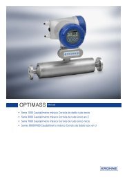
Figure 2-1: Flow velocity vs. accuracy<br />
X [m/s]: flow velocity<br />
Y [%]: deviation from the actual measured value (mv)<br />
Accuracy<br />
Sensor diameter Converter type Accuracy Curve<br />
DN10...150 / 3/8...6" IFC 050 0.5% of mv above 0.5 m/s<br />
3<br />
below 0.5 m/s, deviation ± 2.5 mm/s<br />
DN10...150 / 3/8...6" IFC 100 0.4% of mv + 1 mm/s 2<br />
DN10...150 / 3/8...6" IFC 300 0.3% of mv + 2 mm/s 1<br />
01/2013 - 4000690403 - TD <strong>OPTIFLUX</strong> <strong>1000</strong> R03 en<br />
www.krohne.com<br />
11
2 TECHNICAL DATA<br />
<strong>OPTIFLUX</strong> <strong>1000</strong><br />
2.3 Dimensions and weights<br />
Remote version a = 88 mm / 3.5"<br />
b = 139 mm / 5.5" 1<br />
c = 106 mm / 4.2"<br />
Total height = H + a<br />
Compact version with<br />
IFC 300<br />
a = 155 mm / 6.1"<br />
b = 230 mm / 9.1" 1<br />
c = 260 mm / 10.2"<br />
Total height = H + a<br />
Compact version with<br />
IFC 100 (0°)<br />
a = 82 mm / 3.2"<br />
b = 161 mm / 6.3"<br />
c = 257 mm / 10.1" 1<br />
Total height = H + a<br />
Compact version with<br />
IFC 100 (45°)<br />
a = 186 mm / 7.3"<br />
b = 161 mm / 6.3"<br />
c = 184 mm / 2.7" 1<br />
Total height = H + a<br />
Compact version with<br />
IFC 050 (10°)<br />
a = 101 mm / 3.98"<br />
b = 157 mm / 6.18"<br />
c = 260 mm / 10.24" 1<br />
Total height = H + a<br />
1 The value may vary depending on the used cable glands.<br />
12<br />
www.krohne.com<br />
01/2013 - 4000690403 - TD <strong>OPTIFLUX</strong> <strong>1000</strong> R03 en
<strong>OPTIFLUX</strong> <strong>1000</strong><br />
TECHNICAL DATA 2<br />
• All data given in the following tables are based on standard versions of the flow sensor only.<br />
• Especially for smaller nominal sizes of the flow sensor, the signal converter can be bigger<br />
than the flow sensor.<br />
• Note that for other pressure ratings than mentioned, the dimensions may be different.<br />
• For full information on signal converter dimensions see relevant documentation.<br />
EN 1092-1<br />
Nominal size Dimensions [mm] Approx. weight<br />
[kg]<br />
DN L H W<br />
10 68 137 47 1.7<br />
15 68 137 47 1.7<br />
25 54 147 66 1.7<br />
40 78 162 82 2.6<br />
50 100 151 101 4.2<br />
80 150 180 130 5.7<br />
100 200 207 156 10.5<br />
150 200 271 219 15.0<br />
ASME B16.5<br />
Nominal size Dimensions [inch] Approx. weight<br />
[lb]<br />
ASME L H W<br />
3/8" 2.68 5.39 1.85 3.7<br />
½" 2.68 5.39 1.85 3.7<br />
1" 2.13 5.79 2.6 3.7<br />
1½" 3.07 6.38 3.23 5.7<br />
2" 3.94 5.94 3.98 9.3<br />
3" 5.91 7.08 5.12 12.6<br />
4" 7.87 8.15 6.14 23.1<br />
6" 7.87 10.67 8.62 33.1<br />
01/2013 - 4000690403 - TD <strong>OPTIFLUX</strong> <strong>1000</strong> R03 en<br />
www.krohne.com<br />
13
3 INSTALLATION<br />
<strong>OPTIFLUX</strong> <strong>1000</strong><br />
3.1 Notes on installation<br />
Inspect the cartons carefully for damages or signs of rough handling. Report damage to the<br />
carrier and to the local office of the manufacturer.<br />
Do a check of the packing list to make sure that you have all the elements given in the order.<br />
Look at the device nameplate to ensure that the device is delivered according to your order.<br />
Check for the correct supply voltage printed on the nameplate.<br />
3.2 Intended use<br />
The electromagnetic flowmeter is designed exclusively to measure the flow of electrically<br />
conductive, liquid media.<br />
3.3 Installation conditions<br />
3.3.1 Vibration<br />
Responsibility for the use of the measuring devices with regard to suitability, intended use and<br />
corrosion resistance of the used materials against the measured fluid lies solely with the<br />
operator.<br />
The manufacturer is not liable for any damage resulting from improper use or use for other than<br />
the intended purpose.<br />
Figure 3-1: Avoid vibrations<br />
3.3.2 Magnetic field<br />
Figure 3-2: Avoid magnetic fields<br />
14<br />
www.krohne.com<br />
01/2013 - 4000690403 - TD <strong>OPTIFLUX</strong> <strong>1000</strong> R03 en
<strong>OPTIFLUX</strong> <strong>1000</strong><br />
INSTALLATION 3<br />
3.3.3 Inlet and outlet<br />
Use straight inlet and outlet pipe sections to prevent flow distortion or swirl, caused by bends<br />
and T- sections<br />
Figure 3-3: Recommended inlet and outlet section<br />
1 Refer to chapter "Bends in 2 or 3 dimensions"<br />
2 ≥ 2 DN<br />
3.3.4 Bends in 2 or 3 dimensions<br />
3.3.5 T-section<br />
Figure 3-4: 2 and 3 dimensional bends, in front of flowmeter<br />
1 Bends in 2 dimensions: ≥ 5 DN; bends in 3 dimensions: ≥ 10 DN<br />
Figure 3-5: Distance behind a T-section<br />
1 ≥ 10 DN<br />
01/2013 - 4000690403 - TD <strong>OPTIFLUX</strong> <strong>1000</strong> R03 en<br />
www.krohne.com<br />
15
3 INSTALLATION<br />
<strong>OPTIFLUX</strong> <strong>1000</strong><br />
3.3.6 Bends<br />
Figure 3-6: Installation in bending pipes<br />
Figure 3-7: Installation in bending pipes<br />
Avoid draining or partial filling of the flow sensor<br />
3.3.7 Open discharge<br />
Figure 3-8: Installation in front of an open discharge<br />
16<br />
www.krohne.com<br />
01/2013 - 4000690403 - TD <strong>OPTIFLUX</strong> <strong>1000</strong> R03 en
<strong>OPTIFLUX</strong> <strong>1000</strong><br />
INSTALLATION 3<br />
3.3.8 Flange deviation<br />
Max. permissible deviation of pipe flange faces:<br />
L max - L min ≤ 0.5 mm / 0.02"<br />
3.3.9 Pump<br />
Figure 3-9: Flange deviation<br />
1 L max<br />
2 L min<br />
3.3.10 Control valve<br />
Figure 3-10: Installation behind a pump<br />
Figure 3-11: Installation in front of a control valve<br />
01/2013 - 4000690403 - TD <strong>OPTIFLUX</strong> <strong>1000</strong> R03 en<br />
www.krohne.com<br />
17
3 INSTALLATION<br />
<strong>OPTIFLUX</strong> <strong>1000</strong><br />
3.3.11 Air venting and vacuum forces<br />
Figure 3-12: Air venting<br />
1 ≥ 5 m<br />
2 Air ventilation point<br />
Figure 3-13: Vacuum<br />
1 ≥ 5 m<br />
18<br />
www.krohne.com<br />
01/2013 - 4000690403 - TD <strong>OPTIFLUX</strong> <strong>1000</strong> R03 en
<strong>OPTIFLUX</strong> <strong>1000</strong><br />
INSTALLATION 3<br />
3.3.12 Mounting position<br />
Figure 3-14: Mounting position<br />
3.3.13 Temperatures<br />
Protect the device from direct sunlight.<br />
Temperature range Process [°C] Ambient [°C] Process [°F] Ambient [°F]<br />
min. max. min. max. min. max. min. max.<br />
Separate flow sensor -25 120 -25 65 -13 248 -13 149<br />
Compact + IFC 300 -25 120 -25 65 -13 248 -13 149<br />
Compact + IFC 100 -25 120 -25 65 -13 248 -13 149<br />
Compact + IFC 050 -25 120 -25 65 -13 248 -13 149<br />
01/2013 - 4000690403 - TD <strong>OPTIFLUX</strong> <strong>1000</strong> R03 en<br />
www.krohne.com<br />
19
4 ELECTRICAL CONNECTIONS<br />
<strong>OPTIFLUX</strong> <strong>1000</strong><br />
4.1 Safety instructions<br />
All work on the electrical connections may only be carried out with the power disconnected. Take<br />
note of the voltage data on the nameplate!<br />
Observe the national regulations for electrical installations!<br />
For devices used in hazardous areas, additional safety notes apply; please refer to the Ex<br />
documentation.<br />
Observe without fail the local occupational health and safety regulations. Any work done on the<br />
electrical components of the measuring device may only be carried out by properly trained<br />
specialists.<br />
Look at the device nameplate to ensure that the device is delivered according to your order.<br />
Check for the correct supply voltage printed on the nameplate.<br />
4.2 Grounding<br />
The device must be grounded in accordance with regulations in order to protect personnel<br />
against electric shocks.<br />
Figure 4-1: Grounding<br />
1 Metal pipelines, not internally coated. Grounding without grounding rings!<br />
2 Metal pipelines with internal coating and non-conductive pipelines. Grounding with grounding rings!<br />
Figure 4-2: Grounding ring number 1<br />
Grounding ring number 1 (optional for DN25...150):<br />
• Thickness: 3 mm / 0.1" (tantalum: 0.5 mm / 0.02")<br />
Note: For diameter DN10 and DN15, grounding rings are integrated as standard in the flow<br />
sensor construction.<br />
20<br />
www.krohne.com<br />
01/2013 - 4000690403 - TD <strong>OPTIFLUX</strong> <strong>1000</strong> R03 en
<strong>OPTIFLUX</strong> <strong>1000</strong><br />
ELECTRICAL CONNECTIONS 4<br />
4.3 Virtual reference for IFC 300 (C, W and F version)<br />
The virtual reference option on the IFC 300 flow converter provides complete isolation of the<br />
measurement circuit.<br />
Benefits of virtual reference:<br />
• Grounding rings or grounding electrodes can be omitted.<br />
• Safety increases by reducing the number of potential leakage points.<br />
• The installation of the flowmeters is much easier.<br />
Figure 4-3: Virtual reference<br />
Minimum requirements:<br />
• Size: ≥ DN10<br />
• Electrical conductivity: ≥ 200 µS/cm<br />
• Electrode cable: max. 50 m / 164 ft, type DS<br />
01/2013 - 4000690403 - TD <strong>OPTIFLUX</strong> <strong>1000</strong> R03 en<br />
www.krohne.com<br />
21
5 NOTES<br />
<strong>OPTIFLUX</strong> <strong>1000</strong><br />
22<br />
www.krohne.com<br />
01/2013 - 4000690403 - TD <strong>OPTIFLUX</strong> <strong>1000</strong> R03 en
<strong>OPTIFLUX</strong> <strong>1000</strong><br />
NOTES 5<br />
01/2013 - 4000690403 - TD <strong>OPTIFLUX</strong> <strong>1000</strong> R03 en<br />
www.krohne.com<br />
23
K<br />
K<br />
K<br />
KROHNE product overview<br />
© KROHNE 01/2013 - 4000690403 - TD <strong>OPTIFLUX</strong> <strong>1000</strong> R03 en - Subject to change without notice.<br />
• Electromagnetic flowmeters<br />
• Variable area flowmeters<br />
• Ultrasonic flowmeters<br />
• Mass flowmeters<br />
• Vortex flowmeters<br />
• Flow controllers<br />
• Level meters<br />
• Temperature meters<br />
• Pressure meters<br />
• Analysis products<br />
• Products and systems for the oil & gas industry<br />
• Measuring systems for the marine industry<br />
Head Office KROHNE Messtechnik GmbH<br />
Ludwig-Krohne-Str. 5<br />
47058 Duisburg (Germany)<br />
Tel.:+49 (0)203 301 0<br />
Fax:+49 (0)203 301 10389<br />
info@krohne.de<br />
The current list of all KROHNE contacts and addresses can be found at:<br />
www.krohne.com