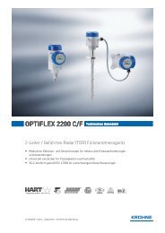
OPTIFLUX 4000
OPTIFLUX 4000
OPTIFLUX 4000

Create successful ePaper yourself
Turn your PDF publications into a flip-book with our unique Google optimized e-Paper software.
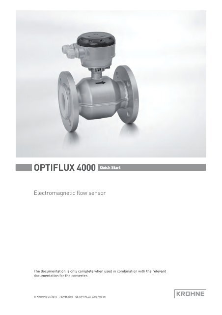
<strong>OPTIFLUX</strong> <strong>4000</strong> Quick Start<br />
Electromagnetic flow sensor<br />
The documentation is only complete when used in combination with the relevant<br />
documentation for the converter.<br />
© KROHNE 04/2010 - 7309852300 - QS <strong>OPTIFLUX</strong> <strong>4000</strong> R03 en
CONTENTS<br />
<strong>OPTIFLUX</strong> <strong>4000</strong><br />
1 Safety instructions 3<br />
2 Installation 4<br />
2.1 Scope of delivery............................................................................................................... 4<br />
2.2 Nameplates ...................................................................................................................... 5<br />
2.3 Storage ............................................................................................................................. 5<br />
2.4 Transport .......................................................................................................................... 5<br />
2.5 Installation conditions ...................................................................................................... 6<br />
2.5.1 Inlet and outlet ........................................................................................................................ 6<br />
2.5.2 Mounting position.................................................................................................................... 6<br />
2.5.3 Flange deviation...................................................................................................................... 7<br />
2.5.4 T-section ................................................................................................................................. 7<br />
2.5.5 Vibration .................................................................................................................................. 7<br />
2.5.6 Magnetic field.......................................................................................................................... 8<br />
2.5.7 Bends ...................................................................................................................................... 8<br />
2.5.8 Open discharge ....................................................................................................................... 9<br />
2.5.9 Control valve ........................................................................................................................... 9<br />
2.5.10 Air venting ............................................................................................................................. 9<br />
2.5.11 Pump ................................................................................................................................... 10<br />
2.5.12 Temperatures ..................................................................................................................... 10<br />
2.5.13 Vacuum load........................................................................................................................ 11<br />
2.6 Mounting......................................................................................................................... 12<br />
2.6.1 Torques and pressures......................................................................................................... 12<br />
3 Electrical connections 15<br />
3.1 Safety instructions.......................................................................................................... 15<br />
3.2 Grounding ....................................................................................................................... 15<br />
3.3 Virtual reference for IFC 300 (C, W and F version) ........................................................ 17<br />
3.4 Connection diagrams ..................................................................................................... 17<br />
4 Technical data 18<br />
4.1 Dimensions and weights ................................................................................................ 18<br />
5 Notes 22<br />
2 www.krohne.com 04/2010 - 7309852300 - QS <strong>OPTIFLUX</strong> <strong>4000</strong> R03 en
<strong>OPTIFLUX</strong> <strong>4000</strong><br />
SAFETY INSTRUCTIONS 1<br />
Warnings and symbols used<br />
DANGER!<br />
This information refers to the immediate danger when working with electricity.<br />
DANGER!<br />
These warnings must be observed without fail. Even partial disregard of this warning can lead to<br />
serious health problems and even death. There is also the risk of seriously damaging the device<br />
or parts of the operator's plant.<br />
WARNING!<br />
Disregarding this safety warning, even if only in part, poses the risk of serious health problems.<br />
There is also the risk of damaging the device or parts of the operator's plant.<br />
CAUTION!<br />
Disregarding these instructions can result in damage to the device or to parts of the operator's<br />
plant.<br />
INFORMATION!<br />
These instructions contain important information for the handling of the device.<br />
HANDLING<br />
• This symbol designates all instructions for actions to be carried out by the operator in the<br />
specified sequence.<br />
i<br />
RESULT<br />
This symbol refers to all important consequences of the previous actions.<br />
Safety instructions for the operator<br />
CAUTION!<br />
Installation, assembly, start-up and maintenance may only be performed by appropriately<br />
trained personnel. The regional occupational health and safety directives must always be<br />
observed.<br />
LEGAL NOTICE!<br />
The responsibility as to the suitability and intended use of this device rests solely with the user.<br />
The supplier assumes no responsibility in the event of improper use by the customer. Improper<br />
installation and operation may lead to loss of warranty. In addition, the "Terms and Conditions of<br />
Sale" apply. They appear on the back of the invoice and form the basis of the purchase contract.<br />
INFORMATION!<br />
• Further information can be found on the supplied CD-ROM in the manual, on the data sheet,<br />
in special manuals, certificates and on the manufacturer's website.<br />
• If you need to return the device to the manufacturer or supplier, please fill out the form<br />
contained on the CD-ROM and send it with the device. Unfortunately, the manufacturer<br />
cannot repair or inspect the device without the completed form.<br />
04/2010 - 7309852300 - QS <strong>OPTIFLUX</strong> <strong>4000</strong> R03 en<br />
www.krohne.com<br />
3
2 INSTALLATION<br />
<strong>OPTIFLUX</strong> <strong>4000</strong><br />
2.1 Scope of delivery<br />
1 Remote version<br />
2 Compact version with IFC 300 signal converter<br />
3 Compact version with IFC 100 (0°) signal converter<br />
4 Compact version with IFC 100 (45°) signal converter<br />
Figure 2-1: Scope of delivery<br />
1 Ordered flowmeter<br />
2 Product documentation<br />
3 Factory calibration report<br />
4 CD-ROM with product documentation<br />
5 Grounding rings (optionally)<br />
6 Cable (remote versions only)<br />
4<br />
www.krohne.com<br />
04/2010 - 7309852300 - QS <strong>OPTIFLUX</strong> <strong>4000</strong> R03 en
<strong>OPTIFLUX</strong> <strong>4000</strong><br />
INSTALLATION 2<br />
2.2 Nameplates<br />
2.3 Storage<br />
INFORMATION!<br />
Look at the device nameplate to ensure that the device is delivered according to your order.<br />
Check for the correct supply voltage printed on the nameplate.<br />
• Store the device in a dry and dust-free location.<br />
• Avoid lasting direct exposure to the sun.<br />
• Store the device in its original packing.<br />
2.4 Transport<br />
Figure 2-2: Transport<br />
04/2010 - 7309852300 - QS <strong>OPTIFLUX</strong> <strong>4000</strong> R03 en<br />
www.krohne.com<br />
5
2 INSTALLATION<br />
<strong>OPTIFLUX</strong> <strong>4000</strong><br />
2.5 Installation conditions<br />
2.5.1 Inlet and outlet<br />
Figure 2-3: Recommended inlet and outlet sections<br />
1 ≥ 5 DN<br />
2 ≥ 2 DN<br />
2.5.2 Mounting position<br />
Figure 2-4: Mounting position<br />
6<br />
www.krohne.com<br />
04/2010 - 7309852300 - QS <strong>OPTIFLUX</strong> <strong>4000</strong> R03 en
<strong>OPTIFLUX</strong> <strong>4000</strong><br />
INSTALLATION 2<br />
2.5.3 Flange deviation<br />
CAUTION!<br />
Max. permissible deviation of pipe flange faces:<br />
L max - L min ≤ 0.5 mm / 0.02"<br />
2.5.4 T-section<br />
Figure 2-5: Flange deviation<br />
1 L max<br />
2 L min<br />
2.5.5 Vibration<br />
Figure 2-6: Distance after T-sections<br />
1 ≥ 10 DN<br />
Figure 2-7: Avoid vibrations<br />
04/2010 - 7309852300 - QS <strong>OPTIFLUX</strong> <strong>4000</strong> R03 en<br />
www.krohne.com<br />
7
2 INSTALLATION<br />
<strong>OPTIFLUX</strong> <strong>4000</strong><br />
2.5.6 Magnetic field<br />
2.5.7 Bends<br />
Figure 2-8: Avoid magnetic fields<br />
Figure 2-9: Installation in bending pipes<br />
Figure 2-10: Installation in bending pipes<br />
8<br />
www.krohne.com<br />
04/2010 - 7309852300 - QS <strong>OPTIFLUX</strong> <strong>4000</strong> R03 en
<strong>OPTIFLUX</strong> <strong>4000</strong><br />
INSTALLATION 2<br />
2.5.8 Open discharge<br />
2.5.9 Control valve<br />
Figure 2-11: Installation before an open discharge<br />
2.5.10 Air venting<br />
Figure 2-12: Installation before control valve<br />
Figure 2-13: Air venting<br />
1 ≥ 5 m<br />
2 Air ventilation point<br />
04/2010 - 7309852300 - QS <strong>OPTIFLUX</strong> <strong>4000</strong> R03 en<br />
www.krohne.com<br />
9
2 INSTALLATION<br />
<strong>OPTIFLUX</strong> <strong>4000</strong><br />
2.5.11 Pump<br />
Figure 2-14: Installation after pump<br />
2.5.12 Temperatures<br />
CAUTION!<br />
Protect the device from direct sunlight.<br />
Temperature range Process [°C] Ambient [°C] Process [°F] Ambient [°F]<br />
min. max. min. max. min. max. min. max.<br />
PTFE<br />
Separate flow sensor -40 180 -40 65 -40 356 -40 149<br />
Compact with IFC 300 -40 140 -40 65 -40 284 -40 149<br />
Compact with IFC 100 -40 140 -40 65 -40 284 -40 149<br />
PFA<br />
Separate flow sensor -40 180 -40 65 -40 356 -40 149<br />
Compact with IFC 300 -40 140 -40 65 -40 284 -40 149<br />
Compact with IFC 100 -40 140 -40 65 -40 284 -40 149<br />
ETFE<br />
Separate flow sensor -40 120 -40 65 -40 248 -40 149<br />
Compact with IFC 300 -40 120 -40 65 -40 248 -40 149<br />
Compact with IFC 100 -40 120 -40 65 -40 248 -40 149<br />
Hard rubber<br />
Separate flow sensor 1 -5 80 -40 65 23 176 -40 149<br />
Compact with IFC 300 1 -5 80 -40 65 23 176 -40 149<br />
Compact with IFC 100 1 -5 80 -40 65 23 176 -40 149<br />
PU<br />
Separate flow sensor -5 65 -40 65 23 149 -40 149<br />
Compact with IFC 300 -5 65 -40 65 23 149 -40 149<br />
Compact with IFC 100 -5 65 -40 65 23 149 -40 149<br />
1 Hard rubber liner is available for Ex-versions only<br />
10<br />
www.krohne.com<br />
04/2010 - 7309852300 - QS <strong>OPTIFLUX</strong> <strong>4000</strong> R03 en
<strong>OPTIFLUX</strong> <strong>4000</strong><br />
INSTALLATION 2<br />
2.5.13 Vacuum load<br />
Diameter<br />
Max.<br />
pressure<br />
Vacuum load in mbar abs. at a process temperature of<br />
[mm] [bar] 40°C 60°C 70°C 80°C 90°C 100°C 120°C 140°C 180°C<br />
Liner in PTFE<br />
DN10...20 50 0 0 0 0 0 0 500 750 1000<br />
DN200...300 50 500 750 1000 1000 1000 1000 1000 1000 1000<br />
DN350...600 50 800 1000 1000 1000 1000 1000 1000 1000 1000<br />
Liner in PFA<br />
DN2.5...150 50 0 0 0 0 0 0 0 0 0<br />
Liner in ETFE<br />
DN200...2000 150 100 100 100 100 100 100 100 - -<br />
Liner in Hard rubber<br />
DN200...300 150 250 400 400 400 - - - - -<br />
DN350...3000 150 500 600 600 600 - - - - -<br />
Liner in PU<br />
DN200...1800 1500 500 600 - - - - - - -<br />
Diameter<br />
Max.<br />
pressure<br />
Vacuum load in psia at a process temperature of<br />
[inches] [psi] 104°F 140°F 158°F 176°F 194°F 212°F 248°F 284°F 356°F<br />
Liner in PTFE<br />
3/8...3/4" 725 0 0 0 0 0 0 7.3 10.9 14.5<br />
8...12" 725 7.3 10.9 14.5 14.5 14.5 14.5 14.5 14.5 14.5<br />
14...24" 725 11.6 14.5 14.5 14.5 14.5 14.5 14.5 14.5 14.5<br />
Liner in PFA<br />
1/10...6" 725 0 0 0 0 0 0 0 0 0<br />
Liner in ETFE<br />
8...72" 2176 1.5 1.5 1.5 1.5 1.5 1.5 1.5 - -<br />
Liner in Hard rubber<br />
8...12" 2176 3.6 5.8 5.8 5.8 - - - - -<br />
14...120" 2176 7.3 8.7 8.7 8.7 - - - - -<br />
Liner in PU<br />
8...72" 21756 7.3 8.7 - - - - - - -<br />
04/2010 - 7309852300 - QS <strong>OPTIFLUX</strong> <strong>4000</strong> R03 en<br />
www.krohne.com<br />
11
2 INSTALLATION<br />
<strong>OPTIFLUX</strong> <strong>4000</strong><br />
2.6 Mounting<br />
2.6.1 Torques and pressures<br />
Figure 2-15: Tightening of bolts<br />
Tightening of bolts<br />
1 Step 1: Apply approx. 50% of max. torque given in table.<br />
2 Step 2: Apply approx. 80% of max. torque given in table.<br />
3 Step 3: Apply 100% of max. torque given in table.<br />
12<br />
www.krohne.com<br />
04/2010 - 7309852300 - QS <strong>OPTIFLUX</strong> <strong>4000</strong> R03 en
<strong>OPTIFLUX</strong> <strong>4000</strong><br />
INSTALLATION 2<br />
Nominal size<br />
DN [mm]<br />
Pressure<br />
ratin g<br />
Bolts<br />
PFA, PTFE, ETFE<br />
Max. torque [Nm]<br />
PU, hard rubber<br />
2.5 PN 40 4 × M 12 32 -<br />
4 PN 40 4 × M 12 32 -<br />
6 PN 40 4 × M 12 32 -<br />
10 PN 40 4 × M 12 7.6 4.6<br />
15 PN 40 4 × M 12 9.3 5.7<br />
20 PN 40 4 × M 12 16 9.6<br />
25 PN 40 4 × M 12 22 11<br />
32 PN 40 4 × M 16 37 19<br />
40 PN 40 4 × M 16 43 25<br />
50 PN 40 4 × M 16 55 31<br />
65 PN 16 4 × M 16 51 42<br />
65 PN 40 8 × M 16 38 21<br />
80 PN 10 8 × M 16 47 25<br />
100 PN 16 8 × M 16 39 30<br />
125 PN 16 8 × M 16 53 40<br />
150 PN 16 8 × M 20 68 47<br />
200 PN 10 8 × M 20 84 68<br />
200 PN 16 12 × M 20 68 45<br />
250 PN 10 12 × M 20 78 65<br />
250 PN 16 12 × M 24 116 78<br />
300 PN 10 12 × M 20 88 76<br />
300 PN 16 12 × M 24 144 105<br />
350 PN 10 16 × M 20 97 75<br />
400 PN 10 16 × M 24 139 104<br />
450 PN 10 20 × M 24 127 93<br />
500 PN 10 20 × M 24 149 107<br />
600 PN 10 20 × M 27 205 138<br />
700 PN 10 20 × M 27 238 163<br />
800 PN 10 24 × M 30 328 219<br />
900 PN 10 28 × M 30 - 205<br />
1000 PN 10 28 × M 35 - 261<br />
04/2010 - 7309852300 - QS <strong>OPTIFLUX</strong> <strong>4000</strong> R03 en<br />
www.krohne.com<br />
13
2 INSTALLATION<br />
<strong>OPTIFLUX</strong> <strong>4000</strong><br />
Nominal size<br />
[inch]<br />
Flange class<br />
[lb]<br />
Bolts<br />
PFA, PTFE, ETFE<br />
Max. torque [Nm]<br />
PU, hard rubber<br />
1/10 150 4 × 1/2" 32 -<br />
1/6 150 4 × 1/2" 32 -<br />
1/4 150 4 × 1/2" 32 -<br />
3/8 150 4 × 1/2" 3.5 3.6<br />
1/2 150 4 × 1/2" 3.5 3.6<br />
3/4 150 4 × 1/2" 4.8 4.8<br />
1 150 4 × 1/2" 6.7 4.4<br />
1 1/2 150 4 × 1/2" 13 12<br />
2 150 4 × 5/8" 24 23<br />
3 150 4 × 5/8" 43 39<br />
4 150 8 × 5/8" 34 31<br />
6 150 8 × 3/4" 61 51<br />
8 150 8 × 3/4" 86 69<br />
10 150 12 × 7/8" 97 79<br />
12 150 12 × 7/8" 119 104<br />
14 150 12 × 1" 133 93<br />
16 150 16 × 1" 130 91<br />
18 150 16 × 1 1/8" 199 143<br />
20 150 20 × 1 1/8" 182 127<br />
24 150 20 × 1 1/4" 265 180<br />
28 150 28 × 1 1/4" 242 161<br />
32 150 28 × 1 1/2" 380 259<br />
36 150 32 × 1 1/2" - 269<br />
40 150 36 × 1 1/2" - 269<br />
14<br />
www.krohne.com<br />
04/2010 - 7309852300 - QS <strong>OPTIFLUX</strong> <strong>4000</strong> R03 en
<strong>OPTIFLUX</strong> <strong>4000</strong><br />
ELECTRICAL CONNECTIONS 3<br />
3.1 Safety instructions<br />
DANGER!<br />
All work on the electrical connections may only be carried out with the power disconnected. Take<br />
note of the voltage data on the nameplate!<br />
DANGER!<br />
Observe the national regulations for electrical installations!<br />
DANGER!<br />
For devices used in hazardous areas, additional safety notes apply; please refer to the Ex<br />
documentation.<br />
WARNING!<br />
Observe without fail the local occupational health and safety regulations. Any work done on the<br />
electrical components of the measuring device may only be carried out by properly trained<br />
specialists.<br />
INFORMATION!<br />
Look at the device nameplate to ensure that the device is delivered according to your order.<br />
Check for the correct supply voltage printed on the nameplate.<br />
3.2 Grounding<br />
DANGER!<br />
The device must be grounded in accordance with regulations in order to protect personnel<br />
against electric shocks.<br />
Figure 3-1: Grounding<br />
1 Metal pipelines, not internally coated. Grounding without grounding rings.<br />
2 Metal pipelines with internal coating and non-conductive pipelines. Grounding with grounding rings.<br />
04/2010 - 7309852300 - QS <strong>OPTIFLUX</strong> <strong>4000</strong> R03 en<br />
www.krohne.com<br />
15
3 ELECTRICAL CONNECTIONS<br />
<strong>OPTIFLUX</strong> <strong>4000</strong><br />
Figure 3-2: Different types of grounding rings<br />
1 Grounding ring number 1<br />
2 Grounding ring number 2<br />
3 Grounding ring number 3<br />
Grounding ring number 1:<br />
• 3 mm / 0.1" thick (tantalum: 0.5 mm / 0.1")<br />
Grounding ring number 2:<br />
• 3 mm / 0.1" thick<br />
• Prevents damage to the flanges during transport and installation<br />
• Especially for flow sensors with PTFE liner<br />
Grounding ring number 3:<br />
• 3 mm / 0.1" thick<br />
• With cylindrical neck (length 30 mm / 1.25" for DN10...150 / 3/8...6")<br />
• Prevents damage to the liner when abrasive liquids are used<br />
16<br />
www.krohne.com<br />
04/2010 - 7309852300 - QS <strong>OPTIFLUX</strong> <strong>4000</strong> R03 en
<strong>OPTIFLUX</strong> <strong>4000</strong><br />
ELECTRICAL CONNECTIONS 3<br />
3.3 Virtual reference for IFC 300 (C, W and F version)<br />
Figure 3-3: Virtual reference<br />
Possible if:<br />
• ≥ DN10<br />
• Electrical conductivity ≥ 200 µS/cm<br />
• Electrode cable max. 50m.<br />
3.4 Connection diagrams<br />
INFORMATION!<br />
The connection diagrams can be found in the documentation of the converter.<br />
04/2010 - 7309852300 - QS <strong>OPTIFLUX</strong> <strong>4000</strong> R03 en<br />
www.krohne.com<br />
17
4 TECHNICAL DATA<br />
<strong>OPTIFLUX</strong> <strong>4000</strong><br />
4.1 Dimensions and weights<br />
Remote version a = 77 mm / 3.1"<br />
b = 139 mm / 5.5" 1<br />
c = 106 mm / 4.2"<br />
Total height = H + a<br />
Compact version with<br />
IFC 300<br />
a = 155 mm / 6.1"<br />
b = 230 mm / 9.1" 1<br />
c = 260 mm / 10.2"<br />
Total height = H + a<br />
Compact version with<br />
IFC 100 (0°)<br />
a = 82 mm / 3.2"<br />
b = 161 mm / 6.3"<br />
c = 257 mm / 10.1" 1<br />
Total height = H + a<br />
Compact version with<br />
IFC 100 (45°)<br />
a = 186 mm / 7.3"<br />
b = 161 mm / 6.3"<br />
c = 184 mm / 2.7" 1<br />
Total height = H + a<br />
1 The value may vary depending on the used cable glands.<br />
INFORMATION!<br />
• All data given in the following tables are based on standard versions of the sensor only.<br />
• Especially for smaller nominal sizes of the sensor, the converter can be bigger than the<br />
sensor.<br />
• Note that for other pressure ratings than mentioned, the dimensions may be different.<br />
• For full information on converter dimensions see relevant documentation.<br />
18<br />
www.krohne.com<br />
04/2010 - 7309852300 - QS <strong>OPTIFLUX</strong> <strong>4000</strong> R03 en
<strong>OPTIFLUX</strong> <strong>4000</strong><br />
TECHNICAL DATA 4<br />
EN 1092-1<br />
Nominal size Dimensions [mm] Approx.<br />
weight [kg]<br />
DN PN [bar] L H W<br />
DIN<br />
ISO<br />
2.5 40 130 - 142 90 3<br />
4 40 130 - 142 90 3<br />
6 40 130 - 142 90 3<br />
10 40 130 1 - 106 90 6<br />
15 40 130 1 200 106 95 6<br />
20 40 150 200 158 105 7<br />
25 40 150 200 140 115 4<br />
32 40 150 200 157 140 5<br />
40 40 150 200 166 150 5<br />
50 40 200 200 186 165 9<br />
65 16 200 200 200 185 9<br />
80 40 200 200 209 200 12<br />
100 16 250 250 237 220 15<br />
125 16 250 250 266 250 19<br />
150 16 300 300 300 285 27<br />
200 10 350 350 361 340 34<br />
250 10 400 450 408 395 48<br />
300 10 500 500 458 445 58<br />
350 10 500 550 510 505 78<br />
400 10 600 600 568 565 101<br />
450 10 600 - 618 615 111<br />
500 10 600 - 671 670 130<br />
600 10 600 - 781 780 165<br />
700 10 700 - 898 895 248<br />
800 10 800 - 1012 1015 331<br />
900 10 900 - 1114 1115 430<br />
1000 10 1000 - 1225 1230 507<br />
1200 6 1200 - 1417 1405 555<br />
1400 6 1400 - 1619 1630 765<br />
1600 6 1600 - 1819 1830 1035<br />
1800 6 1800 - 2027 2045 1470<br />
2000 6 2000 - 2259 2265 1860<br />
1 150 mm for construction according to order code VN03.<br />
04/2010 - 7309852300 - QS <strong>OPTIFLUX</strong> <strong>4000</strong> R03 en<br />
www.krohne.com<br />
19
4 TECHNICAL DATA<br />
<strong>OPTIFLUX</strong> <strong>4000</strong><br />
150 lb flanges<br />
Nominal size Dimensions [inches] Approx. weight<br />
[lb]<br />
ASME PN [psi] L H W<br />
1/10" 284 5.12 5.59 3.50 6<br />
1/8" 284 5.12 5.59 3.50 6<br />
¼" 284 5.12 5.59 3.50 6<br />
3/8" 284 5.12 1 5.08 3.50 12<br />
½" 284 5.12 1 5.08 3.50 12<br />
¾" 284 5.91 5.28 3.88 18<br />
1" 284 5.91 5.39 4.25 7<br />
1 ¼" 284 5.91 5.98 4.62 7<br />
1 ½" 284 5.91 6.10 5.00 11<br />
2" 284 7.87 7.05 5.98 18<br />
3" 284 7.87 8.03 7.50 26<br />
4" 284 9.84 9.49 9.00 40<br />
5" 284 9.84 10.55 10.0 49<br />
6" 284 11.81 11.69 11.0 64<br />
8" 284 13.78 14.25 13.5 95<br />
10" 284 15.75 16.3 16.0 143<br />
12" 284 19.69 18.78 19.0 207<br />
14" 284 27.56 20.67 21.0 284<br />
16" 284 31.50 22.95 23.5 364<br />
18" 284 31.50 24.72 25.0 410<br />
20" 284 31.50 26.97 27.5 492<br />
24" 284 31.50 31.38 32.0 675<br />
1 5.91" for construction according to order code VN03<br />
CAUTION!<br />
• Pressures at 20°C / 68°F.<br />
• For higher temperatures, the pressure and temperature ratings are as per<br />
ASME B16.5 (up to 24") or ASME B16.47 (>24").<br />
• Dimensions for other sizes on request.<br />
20<br />
www.krohne.com<br />
04/2010 - 7309852300 - QS <strong>OPTIFLUX</strong> <strong>4000</strong> R03 en
<strong>OPTIFLUX</strong> <strong>4000</strong><br />
TECHNICAL DATA 4<br />
300 lb flanges<br />
Nominal size Dimensions [inches] Approx. weight<br />
[lb]<br />
ASME PN [psi] L H W<br />
1/10" 741 5.12 5.59 3.75 6<br />
1/8" 741 5.12 5.59 3.75 6<br />
¼" 741 5.12 5.59 3.75 6<br />
3/8" 741 5.12 1 5.24 3.75 15<br />
½" 741 5.12 1 5.24 3.75 15<br />
¾" 741 5.91 5.67 4.62 20<br />
1" 741 5.91 5.71 4.87 11<br />
1 ½" 741 7.87 6.65 6.13 13<br />
2" 741 9.84 7.32 6.50 22<br />
3" 741 9.84 8.43 8.25 31<br />
4" 741 11.81 10.00 10.0 44<br />
6" 741 12.60 12.44 12.5 73<br />
8" 741 15.75 15.04 15.0 157<br />
10" 741 19.69 17.05 17.5 247<br />
12" 741 23.62 20.00 20.5 375<br />
14" 741 27.56 21.65 23.0 474<br />
16" 741 31.50 23.98 25.5 639<br />
20" 741 31.50 28.46 30.5 937<br />
24" 741 31.50 33.39 36.0 1345<br />
1 5.91" for construction according to order code VN03<br />
CAUTION!<br />
• Pressures at 20°C / 68°F.<br />
• For higher temperatures, the pressure and temperature ratings are as per<br />
ASME B16.5 (up to 24") or ASME B16.47 (>24").<br />
• Dimensions for other sizes on request.<br />
04/2010 - 7309852300 - QS <strong>OPTIFLUX</strong> <strong>4000</strong> R03 en<br />
www.krohne.com<br />
21
5 NOTES<br />
<strong>OPTIFLUX</strong> <strong>4000</strong><br />
22<br />
www.krohne.com<br />
04/2010 - 7309852300 - QS <strong>OPTIFLUX</strong> <strong>4000</strong> R03 en
<strong>OPTIFLUX</strong> <strong>4000</strong><br />
NOTES 5<br />
04/2010 - 7309852300 - QS <strong>OPTIFLUX</strong> <strong>4000</strong> R03 en<br />
www.krohne.com<br />
23
KROHNE product overview<br />
© KROHNE 04/2010 - 7309852300 - QS <strong>OPTIFLUX</strong> <strong>4000</strong> R03 en - Subject to change without notice.<br />
• Electromagnetic flowmeters<br />
• Variable area flowmeters<br />
• Ultrasonic flowmeters<br />
• Mass flowmeters<br />
• Vortex flowmeters<br />
• Flow controllers<br />
• Level meters<br />
• Temperature meters<br />
• Pressure meters<br />
• Analysis products<br />
• Measuring systems for the oil and gas industry<br />
• Measuring systems for sea-going tankers<br />
Head Office KROHNE Messtechnik GmbH<br />
Ludwig-Krohne-Str. 5<br />
D-47058 Duisburg (Germany)<br />
Tel.:+49 (0)203 301 0<br />
Fax:+49 (0)203 301 10389<br />
info@krohne.de<br />
The current list of all KROHNE contacts and addresses can be found at:<br />
www.krohne.com