Development of Remote Monitoring System for Tunnel ... - Komatsu
Development of Remote Monitoring System for Tunnel ... - Komatsu
Development of Remote Monitoring System for Tunnel ... - Komatsu

Create successful ePaper yourself
Turn your PDF publications into a flip-book with our unique Google optimized e-Paper software.
<strong>Development</strong> <strong>of</strong> <strong>Remote</strong> <strong>Monitoring</strong> <strong>System</strong><br />
<strong>for</strong> <strong>Tunnel</strong> Machine<br />
Yoshinobu Shimizu<br />
Shegeaki Ashikaga<br />
In recent years, more and more tunnel machines (shields and TBMs) <strong>of</strong> <strong>Komatsu</strong> have been operated<br />
not only in Japan but also in China and other countries. In order to ensure efficient service <strong>of</strong> many tunnel<br />
machines in operation at home and abroad, it is necessary to establish a system which helps prevent<br />
machine troubles be<strong>for</strong>e they happen and which permits taking suitable measures promptly in case some<br />
trouble should occur.<br />
With the remote monitoring system <strong>for</strong> tunnel machine that has been developed recently, it is possible<br />
to link to the Internet the personal computers installed at tunnel construction sites <strong>for</strong> excavation control<br />
and to remote-monitor the conditions <strong>of</strong> the tunnel machines on the screens similar to those used <strong>for</strong><br />
monitoring in the fields. In the personal computers <strong>for</strong> on-site excavation control, data about machine<br />
operations and sensor-supplied in<strong>for</strong>mation are stored in files on a time-serial basis. These files are helpful<br />
<strong>for</strong> factor analysis <strong>of</strong> various troubles. In addition, it is possible to connect the system to the PLCs (sequencers)<br />
that are controlling the tunnel machines in operation and to check the machine conditions in detail and<br />
modify the programs from a remote site.<br />
This paper describes the configuration and features <strong>of</strong> the system and the direction <strong>of</strong> system development<br />
in the future.<br />
Key Words: <strong>Remote</strong> <strong>Monitoring</strong> <strong>System</strong> <strong>for</strong> <strong>Tunnel</strong> Machine, Real-time <strong>Monitoring</strong>, S<strong>of</strong>tware <strong>for</strong> <strong>Remote</strong><br />
Control, Dial-up Connection to the Internet, Collection <strong>of</strong> Machine Data.<br />
1. Purpose <strong>of</strong> development<br />
In many cases, when it comes to checking the condition<br />
<strong>of</strong> a tunnel machine being operated at a tunnel construction<br />
site, it is necessary to dispatch servicepersons to the site. In<br />
recent years, more and more <strong>of</strong> the tunnel machines <strong>of</strong><br />
<strong>Komatsu</strong> have been operated both at home and abroad.<br />
There<strong>for</strong>e, visiting every tunnel construction site to check the<br />
tunnel machine condition would take large amounts <strong>of</strong> money.<br />
Besides, since the conventional excavation control system was<br />
managed by each individual customer, the machine maker could<br />
hardly grasp time-serial data about the machines <strong>of</strong> the<br />
customers. There<strong>for</strong>e, it was difficult <strong>for</strong> the machine maker<br />
to determine proper maintenance timings <strong>for</strong> those machines.<br />
In view <strong>of</strong> those conditions, we developed a remote monitoring<br />
system <strong>for</strong> tunnel machine which permits remote monitoring<br />
<strong>of</strong> tunnel construction sites from the service bases and which<br />
can be used to take suitable measures promptly in case some<br />
trouble should occur and to implement maintenance <strong>of</strong> each<br />
individual machine at the right time.<br />
2003 q VOL. 49 NO.151<br />
<strong>Development</strong> <strong>of</strong> <strong>Remote</strong> <strong>Monitoring</strong> <strong>System</strong><br />
<strong>for</strong> <strong>Tunnel</strong> Machine<br />
— 20 —
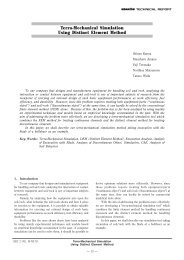
2. Outline <strong>of</strong> the system<br />
The system configuration is shown in Fig. 1.<br />
The operation panel <strong>of</strong> a tunnel machine is equipped with<br />
a PLC <strong>for</strong> controlling the machine. This PLC is used to output<br />
operation commands to the individual actuators and to input<br />
in<strong>for</strong>mation obtained by the sensors that are installed in the<br />
machine. The tunnel machine is also equipped with a<br />
measuring and linearity control system <strong>for</strong> measuring the<br />
current excavation position. This in<strong>for</strong>mation is also input to<br />
the PLC. These pieces <strong>of</strong> in<strong>for</strong>mation about excavation are<br />
transmitted via a modem from the PLC to the personal<br />
computer <strong>for</strong> excavation control installed in the construction<br />
<strong>of</strong>fice on the ground several kilometers away from the tunnel<br />
construction site so that they can be monitored on a real-time<br />
basis. In the construction <strong>of</strong>fice, they collect relevant data and<br />
control the excavation work and machine condition. All this is<br />
the way the conventional control system works at a tunnel<br />
construction site.<br />
In the newly-developed control system, the personal<br />
computers <strong>for</strong> excavation control installed in the individual<br />
construction <strong>of</strong>fices are linked to the Internet so that the same<br />
screens as those displayed on the field personal computers <strong>for</strong><br />
excavation control are displayed on the remote monitoring<br />
personal computers at the service bases. In addition, not only<br />
the in<strong>for</strong>mation obtained by the sensors installed to the<br />
machine but also data about machine operations by switches,<br />
etc. can be collected and transmitted to the remote monitoring<br />
personal computer in the <strong>for</strong>m <strong>of</strong> files. Thus, the same screen<br />
as that <strong>of</strong> the excavation control personal computer in the field<br />
can be seen on a real-time basis and collected data can be<br />
managed at the service base far away from the tunnel<br />
construction site. This means that the service base can grasp<br />
the right maintenance timing <strong>for</strong> each individual tunnel machine<br />
and decide on suitable measures to take in the case <strong>of</strong> some<br />
machine trouble without dispatching any serviceperson to the<br />
construction site.<br />
In addition, since the system employs a trade edition <strong>of</strong><br />
s<strong>of</strong>tware <strong>for</strong> remote control, even if the excavation control<br />
personal computer installed in the field is not one <strong>of</strong> <strong>Komatsu</strong><br />
make, it can be connected directly to the remote monitoring<br />
personal computer. Furthermore, since the remote monitoring<br />
personal computer allows <strong>for</strong> 1-to-n connection, it is possible<br />
to monitor more than one construction site by a single remote<br />
monitoring personal computer <strong>of</strong> the service base.<br />
Shield machine<br />
Operation panel<br />
Actuators<br />
and<br />
sensors<br />
PLC<br />
Yard modem<br />
Survey & linearity<br />
control equipment<br />
Excavation/machine<br />
in<strong>for</strong>mation<br />
Modem<br />
PC <strong>for</strong> field excavation<br />
control (Windows2000)<br />
Yard modem<br />
Field <strong>of</strong>fice<br />
Excavation control<br />
(Linearity control)<br />
Machine monitoring<br />
Documentation function<br />
Preparation <strong>of</strong><br />
daily reports, graphs, etc.<br />
Internet<br />
Service base<br />
Instruction & guidance<br />
Modification <strong>of</strong> PLC<br />
s<strong>of</strong>tware<br />
Modem<br />
PC <strong>for</strong> remote<br />
monitoring<br />
(Windows**)<br />
<strong>Remote</strong> monitoring<br />
<strong>Monitoring</strong> <strong>of</strong> field PC screen<br />
Manipulation <strong>of</strong> field PC files<br />
Modification <strong>of</strong> PLC s<strong>of</strong>tware<br />
Fig. 1 <strong>System</strong> configuration<br />
2003 q VOL. 49 NO.151<br />
<strong>Development</strong> <strong>of</strong> <strong>Remote</strong> <strong>Monitoring</strong> <strong>System</strong><br />
<strong>for</strong> <strong>Tunnel</strong> Machine<br />
— 21 —
3. Functions <strong>of</strong> field excavation control personal<br />
computer<br />
The personal computer <strong>for</strong> excavation control installed in<br />
the ground construction <strong>of</strong>fice at the tunnel construction site<br />
is loaded with an excavation control program prepared <strong>for</strong> each<br />
tunnel machine to per<strong>for</strong>m the functions described below. The<br />
personal computer is also provided with s<strong>of</strong>tware <strong>for</strong> remote<br />
control.<br />
q Real-time monitoring<br />
The amount <strong>of</strong> deviation <strong>of</strong> the tunnel machine being<br />
monitored and the data about machine condition and operation<br />
are displayed on a real-time basis on the screen in the <strong>for</strong>m <strong>of</strong><br />
graphs.<br />
• <strong>Monitoring</strong> <strong>of</strong> excavation condition<br />
An example <strong>of</strong> excavation condition monitoring is shown<br />
in Fig. 2.<br />
The sensor-supplied data (e.g., jack stroke), the<br />
excavation condition (e.g., work mode), and the amount<br />
<strong>of</strong> deviation from the planned line measured by the survey<br />
& linearity control device are displayed directly and in the<br />
<strong>for</strong>m <strong>of</strong> graphs.<br />
• <strong>Monitoring</strong> <strong>of</strong> machine condition<br />
An example <strong>of</strong> machine condition monitoring is shown in<br />
Fig. 3.<br />
In addition to the amount <strong>of</strong> deviation and machinesupplied<br />
data, the current operating condition <strong>of</strong> the<br />
machine is displayed on the screen.<br />
Display <strong>of</strong> excavation condition<br />
Monitor <strong>of</strong> amount <strong>of</strong> deviation<br />
Display <strong>of</strong> time<br />
Diagram showing machine conditions<br />
Fig. 3 Example <strong>of</strong> monitoring <strong>of</strong> machine conditions<br />
• <strong>Monitoring</strong> <strong>of</strong> machine operation<br />
An example <strong>of</strong> machine operation monitoring is shown in<br />
Fig. 4.<br />
The current settings <strong>of</strong> the switches <strong>for</strong> machine<br />
operation and the pumps that have been started are<br />
displayed.<br />
Monitor <strong>of</strong> machine data<br />
Monitor <strong>of</strong> track graph<br />
Fig. 2 Example <strong>of</strong> monitoring <strong>of</strong> excavation conditions<br />
Machine operating conditions<br />
Fig. 4 Example <strong>of</strong> monitoring <strong>of</strong> machine operations<br />
w Collection and recording <strong>of</strong> data<br />
At a preset time interval or after every preset excavation<br />
distance, various types <strong>of</strong> machine data and in<strong>for</strong>mation about<br />
manipulated switches, etc. are saved to a hard disk in the<br />
<strong>for</strong>m <strong>of</strong> files. Since machine data and machine operation<br />
conditions are recorded on a time-serial basis, it allows <strong>for</strong><br />
accurate factor analysis in case some trouble has occurred.<br />
2003 q VOL. 49 NO.151<br />
<strong>Development</strong> <strong>of</strong> <strong>Remote</strong> <strong>Monitoring</strong> <strong>System</strong><br />
<strong>for</strong> <strong>Tunnel</strong> Machine<br />
— 22 —
e Linearity control<br />
Input <strong>of</strong> planned-line data and indication <strong>of</strong> the current<br />
position relative to the planned line. An example <strong>of</strong> display<br />
<strong>for</strong> monitoring is shown in Fig. 5.<br />
Current position<br />
Fig. 5<br />
Target linearity<br />
Example <strong>of</strong> monitoring <strong>of</strong> linearity control<br />
(planned line data)<br />
rDocument control<br />
Preparation <strong>of</strong> daily reports and graphs from recorded<br />
data. The files <strong>of</strong> collected data are in the <strong>for</strong>m <strong>of</strong> text files.<br />
In order to permit utilizing collected data effectively, the<br />
document control s<strong>of</strong>tware that operates on EXCEL develops<br />
the contents <strong>of</strong> the text files on EXCEL and displays the item<br />
names, switch names, etc. contained in the machine data so<br />
as to make the documents easy to read. This is intended also<br />
to facilitate sorting and printing machine data on EXCEL. An<br />
example <strong>of</strong> a daily report is shown in Fig. 6.<br />
4. Functions <strong>of</strong> remote monitoring personal<br />
computer<br />
The remote monitoring personal computer installed at the<br />
service base is loaded with a trade edition <strong>of</strong> s<strong>of</strong>tware <strong>for</strong><br />
remote control to per<strong>for</strong>m the following functions.<br />
q Display<br />
The screen <strong>of</strong> the excavation control personal computer in<br />
the field is directly displayed on the remote monitoring personal<br />
computer on a real-time basis to permit remote monitoring.<br />
w File transfer<br />
Data files stored in the excavation control personal<br />
computer in the field are transferred to the remote monitoring<br />
personal computer. By periodically obtaining recorded data<br />
from the field and monitoring the machine condition, it is<br />
possible to prevent machine troubles be<strong>for</strong>e they happen. In<br />
addition, if some trouble has occurred, it is possible to promptly<br />
analyze factors in the trouble by using the latest data collected<br />
be<strong>for</strong>e the trouble occurred.<br />
e Chat function<br />
The persons in the field and the service base can have a<br />
conversation and exchange messages while watching their<br />
screens.<br />
r Dial-up connection with the Internet<br />
This function connects the excavation control personal<br />
computer in the field to the Internet. An example <strong>of</strong> screen<br />
setting is shown in Fig. 7.<br />
Fig. 7 Example <strong>of</strong> screen <strong>for</strong> dial-up/connection to the Internet<br />
Fig. 6 Example <strong>of</strong> daily report<br />
t <strong>Remote</strong> control<br />
This function permits the remote monitoring personal<br />
computer to work on the system <strong>of</strong> excavation control personal<br />
computers and Windows applications in the field.<br />
y Control <strong>of</strong> PLC <strong>for</strong> controlling machine<br />
By installing the PLC ladder editing s<strong>of</strong>tware (GPP) in<br />
the excavation control personal computer in the field and<br />
connecting the remote controlling personal computer to the<br />
PLC <strong>for</strong> machine control via a modem, it becomes possible <strong>for</strong><br />
2003 q VOL. 49 NO.151<br />
<strong>Development</strong> <strong>of</strong> <strong>Remote</strong> <strong>Monitoring</strong> <strong>System</strong><br />
<strong>for</strong> <strong>Tunnel</strong> Machine<br />
— 23 —
the remote monitoring personal computer to start the ladder<br />
editing s<strong>of</strong>tware <strong>of</strong> the excavation control personal computer<br />
and thereby monitor or control the PLC <strong>for</strong> controlling the<br />
machine. With this function, even the in<strong>for</strong>mation which cannot<br />
be monitored by the excavation control personal computer can<br />
be monitored by the remote monitoring personal computer as<br />
long as it is connected to the PLC. In addition, when it<br />
becomes necessary to modify the PLC s<strong>of</strong>tware, the necessary<br />
modification can be made from the remote monitoring personal<br />
computer (as though the modification were made from the<br />
excavation control personal computer).<br />
5. S<strong>of</strong>tware <strong>for</strong> remote control<br />
The excavation control program installed in the excavation<br />
control personal computer in the field is prepared according<br />
to specifications <strong>of</strong> the tunnel machine used. There<strong>for</strong>e, the<br />
method <strong>of</strong> display, the data handled, etc. differ from one<br />
program to another. Besides, the program installed in the<br />
personal computer must not necessarily be one <strong>of</strong> <strong>Komatsu</strong><br />
make. It would require large amounts <strong>of</strong> investment to develop<br />
a remote monitoring s<strong>of</strong>tware package <strong>for</strong> each <strong>of</strong> excavation<br />
control programs which differ from one field to another.<br />
Besides, it is impracticable because all the tunnel machines in<br />
operation must be controlled independently.<br />
There<strong>for</strong>e, it was decided to install a trade edition <strong>of</strong><br />
remote control s<strong>of</strong>tware in each excavation control personal<br />
computer so as to enable it to deal with diverse situations at<br />
reasonable cost.<br />
6. Connection test results<br />
A personal computer <strong>for</strong> excavation control and a personal<br />
computer <strong>for</strong> remote monitoring, each equipped with a 56k<br />
modem, were connected to an Internet provider by dialing up<br />
from a company telephone to confirm whether or not they would<br />
display data correctly and per<strong>for</strong>m their functions properly while<br />
execution <strong>of</strong> remote control. The communication speed used<br />
was 28.8kbps.<br />
At first, the excavation control program was obtaining<br />
machine data serially from the PLC every one second and<br />
reproducing and displaying the entire screen at that timing.<br />
As long as the excavation control personal computer was<br />
used independently (without implementing remote control), it was<br />
operating properly without any problems with its display capability<br />
and operational per<strong>for</strong>mance. However, when remote control was<br />
put into effect, the operational per<strong>for</strong>mance <strong>of</strong> the excavation<br />
control personal computer declined (i.e., slowdown in speed <strong>of</strong><br />
movement <strong>of</strong> the mouse pointer, display <strong>of</strong> dialogs, etc.).<br />
In addition, at the remote monitoring personal computer,<br />
the time interval <strong>of</strong> screen display (renewal) increased to more<br />
than 10 seconds, showing no real-time capability.<br />
That was ascribable not only to the slow communication<br />
speed but also to the fact that the frequent reproduction <strong>of</strong> the<br />
entire screen caused the volume <strong>of</strong> communication data to<br />
become substantially large. There<strong>for</strong>e, we modified the<br />
excavation control program so that it reproduces only those parts<br />
<strong>of</strong> the screen which undergo an alteration <strong>of</strong> data and/or status.<br />
As a result, the excavation control personal computer<br />
improved in both display capability and operational per<strong>for</strong>mance<br />
to such a level that it would pose no practical problems in<br />
implementing remote monitoring.<br />
We carried out another test assuming our <strong>Komatsu</strong> plant<br />
in Ishikawa Prefecture as the construction site (excavation<br />
control personal computer) and Kanagawa Prefecture as the<br />
service base (remote monitoring personal computer). In this<br />
test, the PLC ladder editing s<strong>of</strong>tware installed in the excavation<br />
control personal computer was started from the remote<br />
monitoring personal computer to modify the PLC s<strong>of</strong>tware. The<br />
two personal computers were connected to the Internet in the<br />
same way as mentioned above.<br />
Because <strong>of</strong> the slow communication speed (28.8kbps), the<br />
response speed was slow. Nevertheless, the modification <strong>of</strong><br />
the PLC program could be made as planned. This fact made<br />
us think that the system would be workable even with such a<br />
slow communication speed.<br />
7. Direction <strong>of</strong> system development in the future<br />
We consider that with a higher communication speed, the<br />
problem <strong>of</strong> slow response observed in the above tests will<br />
dissolve itself. However, unlike business <strong>of</strong>fices or general<br />
homes, construction <strong>of</strong>fices are temporary establishments which<br />
are only needed during the period <strong>of</strong> construction work. In<br />
order to have our customers adopt a high-speed communication<br />
line and the present system <strong>for</strong> the purpose <strong>of</strong> maintenance <strong>of</strong><br />
their machines, it is important to improve not only the hardware<br />
but also the s<strong>of</strong>tware <strong>for</strong> follow-up customer services. In the<br />
future, we intend to put the system into practical use and strive<br />
to become able to <strong>of</strong>fer high levels <strong>of</strong> customer services in<br />
cooperation with the staff <strong>of</strong> Customer Service.<br />
Introduction <strong>of</strong> the writers<br />
Yoshinobu Shimizu<br />
Entered <strong>Komatsu</strong> in 1981.<br />
Currently working in Engineering Center,<br />
Underground Machinery Business<br />
Department, Construction & Mining<br />
Equipment Marketing Division, <strong>Komatsu</strong>.<br />
Shigeaki Ashikaga<br />
Entered <strong>Komatsu</strong> in 1990.<br />
Currently working in Working Gear<br />
<strong>Development</strong> Department, Japanese<br />
Marketing Division, Construction & Mining<br />
Equipment Marketing Division, <strong>Komatsu</strong>.<br />
[A few words from the writers]<br />
We developed the present system with the aim <strong>of</strong> allowing the<br />
cause <strong>of</strong> trouble with a construction machine in operation at a<br />
construction site to be analyzed from a remote site. We also<br />
thought it would be nice if the machine control s<strong>of</strong>tware too could<br />
be modified from the remote site. Our aim has been attained,<br />
even though the system is still in experimental stage. In the future,<br />
we would like to put the system into practical use with the<br />
cooperation <strong>of</strong> the staff <strong>of</strong> Customer Services.<br />
2003 q VOL. 49 NO.151<br />
<strong>Development</strong> <strong>of</strong> <strong>Remote</strong> <strong>Monitoring</strong> <strong>System</strong><br />
<strong>for</strong> <strong>Tunnel</strong> Machine<br />
— 24 —