Create successful ePaper yourself
Turn your PDF publications into a flip-book with our unique Google optimized e-Paper software.
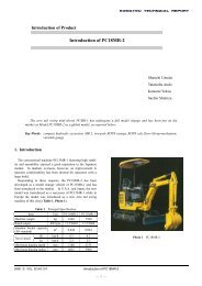
Introduction of Product<br />
<strong>BR1000JG</strong>-1 <strong>Mobile</strong> <strong>Crusher</strong><br />
Takumi Onoda<br />
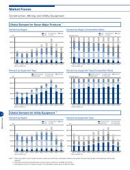
KOMATSU has proposed “on-site recycling method” to crush and reuse concrete debris generated when<br />
a building is demolished and natural stones dug out during civil engineering work with mobile crusher,<br />
and marketed GARA-PAGOS series for this purpose. For 48-inch class, which is the main market in the<br />
quarry industry where jaw crusher has traditionally been used, KOMATSU designed a peculiar 50-inch<br />
crusher. This crusher not only realizes a large treatment capacity but also remarkably improves operability<br />
and maintainability by employing lock cylinder mechanism to facilitate the adjustment of discharge clearance<br />
and eliminate the down time due to clogging of foreign material. This crusher is installed in newly<br />
developed <strong>BR1000JG</strong>-1 <strong>Mobile</strong> <strong>Crusher</strong>, which has recently made its appearance on the market.<br />
Key Words: GARA-PAGOS, <strong>Mobile</strong> <strong>Crusher</strong>, Jaw <strong>Crusher</strong>, Hydraulically Adjustable Jaw, Quarry<br />
1. Introduction<br />
Various debris from construction work some dozen years ago<br />
. Concrete debris from demolished buildings, etc.<br />
. Asphalt debris from road repairing work<br />
. Natural rocks from civil engineering work<br />
The debris was transported to disposal sites.<br />
Environmental and economic problems occurred due to rising<br />
disposal costs from a shortage of disposal sites and<br />
transportation of debris and new aggregates by dump<br />
trucks.Under such social circumstances, in 1992 <strong>Komatsu</strong><br />
introduced mobile crusher BR60 equipped with an impact<br />
crusher for the purpose of “on-site treatment of miscellaneous<br />
debris from the demolition of wooden houses .”In 1993,<br />
<strong>Komatsu</strong> developed BR200J-1 with increased capacity and<br />
equipped with a jaw crusher capable of disposing of large<br />
masses in large-scale demotion and civil engineering work to<br />
promote on-site recycling method.Later the workability was<br />
improved by applying a three-way loading structure and a<br />
conveyor with increased discharge height. A vibratory feeder<br />
to remove muck, and automatic feeding control was installed<br />
to increase production. In August last year, <strong>Komatsu</strong> began<br />
the sale of BR380JG-1 equipped with a crusher of improved<br />
maintainability and operability through its own development.<br />
This machine continues to sell steadily.<br />
On the other hand, separate from the field of disposal by<br />
crushing of debris from construction work , the following<br />
method has been conventionally adopted in the quarry field<br />
where the jaw crusher was originally used:<br />
. After blasting, blasted rocks are collected by a bulldozer.<br />
. Rocks are loaded on a dump truck by a hydraulic excavator<br />
or wheel loader and transported to a crushing plant.<br />
At some sites where the benches height is large, an open<br />
chute method is adopted to drop blasted rocks with the<br />
bulldozer. As exploitation proceeds, however, distance between<br />
the working face and the aggregate production plant becomes<br />
greater causing the hiking of blasted rock transportation costs<br />
to the plant.To cope with the circumstances, a new method<br />
has been adapted by which a mobile crusher is arranged near<br />
the working face as the primary crushing equipment, and the<br />
primarily crushed rocks are transported by either a conveyor<br />
or a 10-ton dump truck to the secondary crushing plant and<br />
onward. At <strong>Komatsu</strong> we can carry out primary crushing at the<br />
working face, then transport the primarily crushed rocks over<br />
the conveyor with a combination of a mobile crusher BR1600JG<br />
and mobile conveyor BM2014C.Moreover, <strong>Komatsu</strong> proposed<br />
the following systems using mobile crushers in the quarry field:<br />
— 1 —
New quarry development system<br />
Enables efficient development of a new quarry by a<br />
combination of a mobile crusher and a loader, requiring no<br />
electric power supply or foundation work for fixed type<br />
crushing plant. Thus, primary crushing can be done in a<br />
narrow space, and crushing site can be moved according to<br />
the quarry site formation after stripping.<br />
Working face on-site production system<br />
Enables production of aggregate in the working face and<br />
product delivery directly from there. <strong>Mobile</strong> crushers perform<br />
primary and secondary crushing and crushed rocks are sorted<br />
with mobile screens within the working face. These mobile<br />
machines allow flexible movement from one working face to<br />
another. In addition, aggregate products can be transported in<br />
a 10-ton dump truck which requires minimum road<br />
construction, contributing to environmental load reduction.<br />
Under those proposals, <strong>Komatsu</strong> has developed and<br />
marketed the large-type mobile crushers, BR500JG-1, BR550JG-<br />
1, and BR1600JG-1.<br />
We have also developed and begun marketing <strong>BR1000JG</strong>-<br />
1 equipped with a jaw crusher of the 48-inch class which is<br />
predominant in the quarry field. The general profile of this<br />
new machine is as follows:<br />
2. Aim of development<br />
<strong>BR1000JG</strong>-1 aims at<br />
. meeting diversified needs for mining equipment, and<br />
. mobility to follow working face location changes.<br />
It is a product with that has unprecedented functions with<br />
the original 50-inch jaw crusher newly designed and<br />
manufactured by <strong>Komatsu</strong>.<br />
Table 1 indicates the development aim of <strong>BR1000JG</strong>-1<br />
and achievement methods. The following section will describe<br />
detailed achievement methods.<br />
In addition, Photo 1 shows an overall appearance picture<br />
of <strong>BR1000JG</strong>; Table 2 the main specifications, and Fig. 1 a<br />
general view.<br />
Photo 1 Overall appearance of <strong>BR1000JG</strong><br />
Table 2 Main specifications<br />
Item Unit <strong>BR1000JG</strong><br />
Performance<br />
Maximum treatment capacity *1<br />
Maximum feed-in size *2<br />
t/h<br />
mm<br />
800<br />
1,200X1,000X750<br />
Travel speed<br />
Gradeability<br />
km/h<br />
Degree<br />
1.7<br />
20<br />
Engine<br />
Model<br />
SAA6D140E<br />
Flywheel horsepower<br />
kW(PS) 338(460)/1,800<br />
Operating weight<br />
kg 93,000<br />
Overall length<br />
mm 16,400<br />
Dimensions<br />
<strong>Crusher</strong><br />
Hopper<br />
Feeder<br />
Hopper feed-in height (rear/side)<br />
Overall width<br />
Conveyor discharge height<br />
Length of track on ground<br />
Minimum ground clearance<br />
Model<br />
Inlet size<br />
Discharge clearance<br />
(opening side)<br />
Capacity<br />
(upper surface of the pan)<br />
Length x width<br />
Model<br />
mm<br />
mm<br />
mm<br />
mm<br />
mm<br />
<br />
mm<br />
mm<br />
m 3<br />
mm<br />
<br />
5,300/5,640<br />
4,465<br />
3,000<br />
4,250<br />
450<br />
Single toggle<br />
1,260X1,0000<br />
125 280<br />
Conveyor Belt width<br />
mm 1,200<br />
*1: Treatment capacity is the sum of the quantity of the material crushed<br />
by the crusher and the quantity of the material that passed through<br />
the grizzly bar. It depends on the type and properties of the<br />
materials and the working condition.<br />
*2: The maximum feed-in size means the maximum size of the materials<br />
that can be crushed when it is supplied in a proper direction.<br />
8.2<br />
5,500X3,650<br />
Two-stage<br />
grizzly bars<br />
Development aim<br />
Meeting diversified needs<br />
for mining equipment<br />
Meeting the changes of<br />
the working face location<br />
Others<br />
Large throughput<br />
Easy operation<br />
Mobility<br />
Ease of disassembly<br />
transportation<br />
Reliability and<br />
durability<br />
Table 1 Development aim and the achievement methods<br />
Reduction of operating<br />
cost<br />
Maintainability and<br />
safety<br />
Achievement methods<br />
50-inch jaw crusher, the largest for 48-inch class<br />
Large hopper and large capacity conveyor<br />
Automatic adjustment function for crusher discharge clearance<br />
Employment of toggle plate protective device for clogging with foreign material<br />
One-man operation<br />
Fully hydraulic-driven system including the crusher<br />
Optimized swing jaw plate locus and improved wear life through the adoption of<br />
up-thrust mechanism<br />
Superb travel performance with the remote travel control<br />
5-unit tear down structure (3.2 m wide x 3.2 m high with mass of under 32 tons)<br />
Use of components common to <strong>Komatsu</strong> construction equipment<br />
Adoption of construction equipment-based hydraulic and electronic control system<br />
Installation of protective guard to the rear of the conveyor<br />
Centralized arrangement of operating switches and monitor to enable operation<br />
from the ground<br />
— 2 —
Overall width4465<br />
4170(LARGE)<br />
3650(STD)<br />
3180<br />
3150<br />
5500<br />
1260<br />
Inlet to <strong>Crusher</strong><br />
belt width1200<br />
Overall height 5640(STD)<br />
2590<br />
3190<br />
600<br />
Overall height 5860(LARGE)<br />
3150<br />
2150<br />
Minimum ground<br />
clearance450<br />
4250<br />
7410<br />
Overall length16400<br />
37<br />
7265<br />
3090<br />
3000<br />
3265<br />
Fig. 1 General view<br />
3. Introduction of achievement methods<br />
3-1 Large throughput<br />
(1) The largest jaw crusher in this class<br />
A 50-inch hydraulic driven jaw crusher provides a large<br />
production capacity , largest in this class (inlet size of 1,260 x<br />
1,000 mm)<br />
(2) Large hopper and wide crusher discharge port<br />
Equipped with a large folding type hopper having a<br />
capacity of 8.2 m 3 , it enables loading using a hydraulic<br />
excavator of the 3 to 4 m 3 bucket capacity class. (Photo. 2)<br />
Regarding automatic adjustment of discharge clearance, a<br />
conventional crusher is constructed as shown in Fig. 2. To<br />
adjust the discharge clearance, it is necessary to carry on a<br />
series of work as follows using heavy shims and large tools:<br />
Loosen the toggle block tension bolt.<br />
Extend the hydraulic ram with a manual pump.<br />
Remove shims (when expanding clearance) or insert them<br />
(when reducing clearance).<br />
Retract the hydraulic ram with a manual pump.<br />
Tighten the toggle block tension bolt.<br />
Check that the desired clearance is obtained using a<br />
discharge clearance measuring jig.<br />
Cheek plate<br />
(divided into two)<br />
Flywheel<br />
Photo 2 Hopper<br />
Shims<br />
Toggle block<br />
tension bolt<br />
3-2 Easy operation<br />
(1) Hydraulic lock cylinder is installed on the crusher<br />
Adoption of a special-structured lock cylinder has added<br />
the following functions:<br />
. Automatic discharge clearance adjustment function<br />
Clearance adjusted by extending the cylinder (reducing<br />
clearance) or retracting (increasing clearance)<br />
. Toggle plate protection function when the crusher is<br />
clogged with foreign material<br />
When clogged with foreign material, the cylinder piston<br />
forcibly slides to open the discharge clearance to release<br />
the load.<br />
Bow-type<br />
fixed plate<br />
Swing jaw plate<br />
Toggle plate<br />
Hydraulic ram<br />
Discharge clearance<br />
adjustment<br />
Fig. 2 <strong>Crusher</strong> construction of conventional machine<br />
— 3 —
<strong>BR1000JG</strong>-1 can reduce or increase clearance by<br />
controlling the lock cylinder in the crusher structure shown<br />
in Fig. 3. This can be effected by operating the monitor switch<br />
in the control panel operable from the ground. Since the<br />
discharge clearance detected by the sensor is displayed on the<br />
monitor, no discharge clearance adjustment jig is needed to<br />
check the clearance. This enables the operator to adjust the<br />
discharge clearance from the ground without riding on the<br />
machine.<br />
Fixed jaw plate<br />
Swing jaw plate<br />
Lock cylinder<br />
sensor detects that this lock cylinder has retracted with a forced<br />
sliding of the cylinder piston and work equipment completely<br />
stops to protect the toggle plate.The lock cylinder is locked<br />
with the cylinder tube and the piston in the state of shrink fit.<br />
By structure, if an external force exceeding the locking force<br />
is applied to the cylinder, the locking force yields to the<br />
external force and the cylinder retracts. To have the lock<br />
cylinder extend or retract like a normal cylinder, apply<br />
hydraulic pressure to the unlock port. Then the cylinder tube<br />
bulges and unlocks the piston to enable the cylinder to extend<br />
or retract.<br />
Fig. 5 shows a structural diagram of the lock cylinder<br />
and Table 3 indicates the state of the lock cylinder (piston).<br />
When locked<br />
Piston Cylinder tube<br />
Unlock port<br />
Discharge<br />
clearance<br />
Toggle plate<br />
Fig. 3 Structure of <strong>BR1000JG</strong>-1<br />
Link<br />
When adjusting<br />
Unlock por<br />
The multi-function monitor on the control panel is used<br />
for adjusting discharge clearance. Clearance can be set in the<br />
following three modes:<br />
In Mode A, discharge clearance can be adjusted by<br />
entering the desired clearance between 125 and 280 mm using<br />
the clearance setting input switch. In Mode A, first the<br />
clearance reduces until the swing jaw plate makes contact with<br />
the fixed jaw plate. This point is recognized as actual clearance<br />
zero (0) in order to compensate the worn portion of the jaw<br />
plates. Then the clearance begins to expand until the entered<br />
clearance is reached, thus completing the adjustment.<br />
In Mode S, clearance is adjusted by entering increasing/<br />
decreasing amount from the current discharge clearance using<br />
the clearance setting input switch.<br />
In Mode M, clearance can be reduced or expanded by<br />
operating the manual setting adjustment switch. Use this mode<br />
when removing clogged foreign material by opening the<br />
clearance to the maximum.<br />
Fig. 4 shows the clearance adjustment screen of the<br />
control panel and the switch section.<br />
Table 3<br />
Normal load<br />
Lock<br />
Fig. 5 Structure of lock cylinder<br />
The state of the lock cylinder (piston)<br />
During work<br />
Clogging of foreign material<br />
Forced sliding<br />
During clearance adjustment<br />
Hydraulic unlocking<br />
(2) One-man operation<br />
A single loader operator can operate a <strong>BR1000JG</strong> with the<br />
following features:<br />
. Automatic feeder control in response to an excessive<br />
crusher load<br />
. Feeder speed setting in response to working conditions<br />
. Stopping and controlling of work equipment with an<br />
optional radio controller (Photo 3 )<br />
Fig. 4 Control panel (for clearance adjustment)<br />
Photo 3 Radio controller (optional)<br />
Toggle plate protection function when the crusher is<br />
clogged with foreign material. When the crusher is clogged<br />
with foreign material and loaded with an excessive load<br />
exceeding the lock cylinder retention force, the clearance<br />
— 4 —
(3) Fully hydraulic driving of work equipment<br />
The hydraulic-driven crusher increases the crushing<br />
torque and enables restarting after clogging stop. This reduces<br />
machine downtime.<br />
. Releasing the crusher from blocking by removing large<br />
rocks from crusher inlet<br />
. Restarting equipment when the crushing chamber is<br />
clogged with rocks<br />
3.3 Reduction of operating cost<br />
As a single toggle crusher specially designed for crushing<br />
blasted rocks , this machine aims at developing a double toggle<br />
locus of the swing jaw plate by adopting up-thrust linkage to<br />
extend the wear life of fixed jaw plates.<br />
Table 4 outlines the up-thrust linkage and down-thrust<br />
linkage adopted for the series machines of <strong>Komatsu</strong>.<br />
<br />
Because of the fixed jaw plate relative angle 1 >swing jaw<br />
plate angle 2 ,rock is less likely to slide on the fixed jaw plate<br />
and the fixed jaw plate is less prone to wear than the swing<br />
jaw plate.<br />
Table 4 Relationship between crusher linkage and plate wear<br />
Item<br />
Construction<br />
Relationship<br />
between the<br />
swing jaw plate<br />
locus and<br />
relative angle<br />
Early wearing<br />
plate<br />
<strong>BR1000JG</strong><br />
(Up-thrust linkage)<br />
Toggle plate upward<br />
Swing jaw<br />
plate locus<br />
Fixed<br />
jaw plate<br />
Fixed jaw plate<br />
relative angle<br />
1<br />
2<br />
Swing jaw plate<br />
Toggle<br />
plate<br />
Swing<br />
jaw plate<br />
Swing jaw plate<br />
relative angle<br />
<strong>Komatsu</strong> series machines<br />
(down-thrust linkage)<br />
Toggle plate downward<br />
Swing jaw plate<br />
relative angle<br />
Fixed<br />
jaw plate<br />
1 2 1 2<br />
2<br />
Swing jaw<br />
plate locus<br />
1<br />
Toggle<br />
plate<br />
Swing jaw<br />
plate<br />
Fixed jaw plate<br />
relative angle<br />
Fixed jaw plate<br />
3.4 Mobility<br />
Able to remote-control travel by large traction force while<br />
checking the surrounding conditions from the ground (Photo 4)<br />
Photo 5 Disassembled unit for transportation (crusher)<br />
3.6 Reliability and durability<br />
(1) Use of components common to komatsu construction<br />
equipment<br />
Components common to <strong>Komatsu</strong> construction equipment<br />
are used for the engine, pump, motor, controller, and other<br />
main components.<br />
(2) Protection of the conveyor rear section<br />
The following structures prevent the conveyor from being<br />
damaged by large debris falling during loading: (Photo 6)<br />
. Side: The tail length of the conveyor has been reduced<br />
and arranged within track width.<br />
. Rear: A conveyor protection guard has been installed.<br />
Photo 6 Conveyor tail section<br />
3.7 Maintainability and safety<br />
(1) Centralized control panel for operation and monitoring<br />
A centralized control panel enables operation and<br />
monitoring from the ground. This enables the loader operator<br />
to operate the crusher with ease.If any trouble occurs , the<br />
monitor displays the error content and specifies abnormal<br />
sections to reduce maintenance hours and machine downtime.<br />
(2) Wide deck and steps<br />
A wide deck and steps are provided around the power<br />
unit and crusher to retain maintenance space. (Photo 7)<br />
Photo 4 State of traveling<br />
3.5 Ease of disassembly transportation<br />
A 5-unit tear down structure is optimal for transportation<br />
and facilitates re-assembly in job site(3.2 m wide x 3.2 m high<br />
x mass of under 32 tons). (Photo 5)<br />
Photo 7 Deck and steps<br />
— 5 —
4. Cases of actual operation<br />
Two users to whom we delivered the machine put it to<br />
different uses respectively.The first user uses the machine for<br />
producing rubbles.<br />
(1) They use the machine with the discharge clearance open<br />
to the maximum.<br />
(2) They use a large wave ridge jaw plate with smaller number<br />
of waves for coarse crushing.<br />
Another user uses the machine as the primary crusher to<br />
feed material to a secondary plant.<br />
Fig. 6 shows the relationship between the existing plant<br />
facilities and <strong>BR1000JG</strong>-1.By feeding a part of the existing<br />
secondary crushing plant with rocks primarily crushed by<br />
<strong>BR1000JG</strong> at the working face, this user is able to process<br />
different types of rocks simultaneously at the secondary<br />
crushing plant to produce different types of aggregates for<br />
shipment. In addition, this user can now have <strong>BR1000JG</strong> travel<br />
to other working faces for crushing rocks and produce<br />
aggregates on the spot to meet market needs promptly.<br />
Primary crushing plant<br />
Blasted rock A Blasted rock B Blasted rock C<br />
Surge pile<br />
Secondary crushing<br />
plant<br />
Self-travel between<br />
working faces<br />
Products Products Products Products Products Products<br />
Products<br />
Fig. 6 Relationship between the plant facilities and <strong>BR1000JG</strong>-1<br />
Introduction of the writer<br />
Takumi Onoda<br />
Entered KOMATSU in 1985<br />
Currently belongs to the<br />
Environmental Recycling Dept., Japanese<br />
Marketing Division<br />
[A few words from the writer]<br />
Twelve years have passed since our market introduction<br />
of the BR60. Recently, GARAPAGOS has come to stand for<br />
mobile crushers in the market, which has already become a<br />
general name for this type of machine in the civil engineering<br />
and demolishing industries. The <strong>BR1000JG</strong>-1 that we are<br />
introducing at present has been developed as a primary<br />
crushing work machine for large scale civil engineering work<br />
such as dam construction and quarrying. While machine<br />
reliability is strongly demanded in these fields, the two<br />
currently operating machines have been working soundly with<br />
little interruption, thanks to the machine designers’ efforts.<br />
Also, this model has been highly evaluated by other users. We<br />
will continue to exert our best sales efforts, encouraged by<br />
this high reputation.<br />
— 6 —