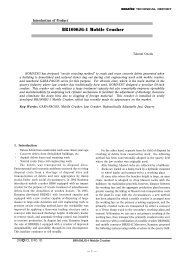
Introduction of PC18MR-2 - Komatsu
Introduction of PC18MR-2 - Komatsu
Introduction of PC18MR-2 - Komatsu

You also want an ePaper? Increase the reach of your titles
YUMPU automatically turns print PDFs into web optimized ePapers that Google loves.
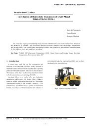
<strong>Introduction</strong> <strong>of</strong> Product<br />
<strong>Introduction</strong> <strong>of</strong> <strong>PC18MR</strong>-2<br />
Shinichi Umeda<br />
Takenobu Ando<br />
Katsumi Yokoo<br />
Sachio Shimizu<br />
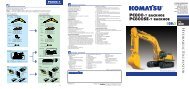
The zero tail swing mini-shovel PCMR-1 has undergone a full model change and has been put on the<br />
market as Model <strong>PC18MR</strong>-2 as a global model, as reported below.<br />
Key Words: compact hydraulic excavator, MR-2, two-pole ROPS canopy, ROPS cab, floor tilt-up mechanism,<br />
variable guage<br />
1. <strong>Introduction</strong><br />
The conventional machine PC15MR-1 featuring high stability<br />
and operability enjoyed a good reputation in the Japanese<br />
market. In markets overseas, however, an improvement in<br />
operator comfortability has been desired for operators with a<br />
large build.<br />
Responding to these requests, the <strong>PC18MR</strong>-2 has been<br />
developed as a model change vehicle <strong>of</strong> PC15MR-1 and has<br />
been introduced to the market. In U.S.A. and Japan, the new<br />
model was instroduced as a successor <strong>of</strong> PC15MR-1 while in<br />
Europe the model was introduced as a new zero tail swing<br />
machine <strong>of</strong> this class (Table 1, Photo 1).<br />
Table 1 Principal Specification<br />
Item Unit <strong>PC18MR</strong>-2 PC15MR-1<br />
Machine weight kg 1640 1590<br />
Rated output kW/rpm 11.2/2600 11.2/2600<br />
Standard bucket capacity<br />
(JIS standard)<br />
Travel speed<br />
m 3 0.044 0.044<br />
Hi km/h 4.3 4.3<br />
Lo km/h 2.3 2.3<br />
Maximum digging depth mm 2160 2155<br />
Maximum digging radius mm 4025 3900<br />
Photo 1 <strong>PC18MR</strong>-2<br />
2006 1 VOL. 52 NO.157 <strong>Introduction</strong> <strong>of</strong> <strong>PC18MR</strong>-2<br />
― 1 ―
2. Aim <strong>of</strong> Development<br />
In response to needs inside and outside <strong>of</strong> Japan, the new<br />
model has been developed to incorporate the same<br />
catchphrases <strong>of</strong> PC20-50MR-2, “safety, roominess, soundness”<br />
as development concepts.<br />
Table 2 Development concepts<br />
Principal selling points (Development concepts)<br />
Item Feature<br />
Safety Two-pole ROPS canopy<br />
Conformance to ultra low noise regulation <strong>of</strong> the<br />
Japanese Land and Infrastructure Ministry, EU new tier<br />
noise regulation<br />
Conformance with Tier-2 exhaust gas regulations<br />
Lock lever that locks entire operations<br />
Retractable seat belt<br />
Engine neutral start mechanism<br />
Roominess<br />
Easier getting into and alighting from seat<br />
Larger operator seat space<br />
(walkthrough)<br />
Soundness<br />
Larger space around a seat<br />
Floor tilting up structure<br />
Full open structure<br />
500 hour interval between maintenance services<br />
Metal plates as exterior machine covers<br />
Less loosening <strong>of</strong> pin play <strong>of</strong> work equipment<br />
3. Principal Features<br />
3.1 ROPS cab<br />
The European-specification equipment can now mount a cab<br />
to meet the needs in Europe for a cab (No cab mounting for<br />
U.S.A. or Japan). Through a review <strong>of</strong> the machine body<br />
layout and design <strong>of</strong> the revolving frame matching the cab<br />
pr<strong>of</strong>ile as described below, a cab could be mounted for the first<br />
time in the world as a zero tail swing machine <strong>of</strong> this class.<br />
The cab adopts a round sliding door that can be opened and<br />
closed even at a narrow site and it complies with ROPS (Fig.<br />
1).<br />
3.2 Features <strong>of</strong> <strong>PC18MR</strong>-2 (variable gauge)<br />
The structure <strong>of</strong> the variable gauge was reviewed with<br />
<strong>PC18MR</strong>-2 to install a cab. The conventional machine<br />
PC15MR-1 had a link-type structure. In case <strong>of</strong> this structure<br />
and if the distance between the legs is small, this leg structure<br />
would cause “falling forward” <strong>of</strong> the equipment that is installed<br />
with a cab and whose center <strong>of</strong> gravity is high, after the side<br />
frame moves back and forth. The <strong>PC18MR</strong>-2 has a<br />
sliding-type structure to prevent this (Fig. 2).<br />
PC15MR-1<br />
Fig. 2 Variable leg structure<br />
<strong>PC18MR</strong>-2<br />
3.3 Common features with MR-2<br />
The following features are common with the upper models<br />
<strong>of</strong> MR-2 (PC20 to 50MR-2).<br />
(1) Operator seat space largest for class<br />
In the past, the operator space in mini-excavators has been<br />
small, sometimes forcing the operator to endure discomfort.<br />
The space has been small especially for operators with a large<br />
build exceeding 170cm in height.<br />
In a market survey undertaken in Europe and U.S.A. prior to<br />
the development work, the first request item for improvement<br />
was an expansion <strong>of</strong> the operator space. More space around<br />
the feet especially was desired and this was accomplished by<br />
taking the following actions (Fig. 3).<br />
Fig. 1 <strong>PC18MR</strong>-2 equipped with cab<br />
2006 1 VOL. 52 NO.157 <strong>Introduction</strong> <strong>of</strong> <strong>PC18MR</strong>-2<br />
― 2<br />
―
Areas expanded compared<br />
with existing machines<br />
Center <strong>of</strong> swing<br />
Unit <strong>PC18MR</strong>-2 PC15MR-1 PC78US-6<br />
Space Width mm 960 780 940<br />
around Depth mm 576 456 600<br />
feet Width×depth cm 2 5530 3557 5640<br />
Fig. 3 Comparison <strong>of</strong> space around feet<br />
1) The machine body layout was reviewed and the fuel tank<br />
that was placed in the space around the right foot was<br />
moved to the rear <strong>of</strong> the machine body. Instead, the fuel<br />
tank is mounted on a counterweight and more space is now<br />
provided (Fig. 4).<br />
regulations on visibility and other items.<br />
The new model was developed based on the following<br />
concepts.<br />
1) To safeguard the operator against falling <strong>of</strong> foreign material<br />
and machine roll-over regardless <strong>of</strong> whether or not<br />
regulations were enforced.<br />
2) To avoid any additional cost to the customers for remodeling<br />
accomplished to meet new regulations in case stricter<br />
regulations are enforced in the future.<br />
3) To develop and provide as a standard specification a<br />
two-pole ROPS (roll-over protective structure) canopy to<br />
satisfy “easier getting into and getting out <strong>of</strong> the cab” and<br />
“visibility” to render remodeling after resale unnecessary<br />
when machines are resold to overseas markets. These two<br />
features are common, standard specifications throughout<br />
the world.<br />
The canopy base is forged and has sufficient strength as a<br />
ROPS canopy, meeting both design and productivity performance<br />
(Photo 2).<br />
Pipe<br />
Forging (Base)<br />
Counterweight<br />
Fuel tank<br />
Photo 2 ROPS canopy<br />
Tuned to the installation <strong>of</strong> a ROPS canopy, a seat belt is<br />
now supplied as a standard specification. The seat belt is<br />
retractable for operator convenience (Fig. 5).<br />
Fig. 4 Fuel tank mounted on counterweight<br />
Retractable seat<br />
belt<br />
2) The 2nd speed pedal was eliminated by adopting an<br />
automatic gear shift mechanism for traveling.<br />
3) Easier getting into and getting out <strong>of</strong> the cab through a<br />
change in canopy structure (Described later)<br />
(2) Two pole ROPS canopy<br />
The conventional machines came with two types <strong>of</strong> canopy,<br />
namely, the TOPS (mini-excavator protective structure at<br />
turning over) canopy and the so-called dual-foot s<strong>of</strong>t canopy.<br />
The TOPS canopy had four poles and was inferior to the s<strong>of</strong>t<br />
canopy in “easier getting into and getting out <strong>of</strong> the cab” and<br />
“visibility.”<br />
The TOPS canopy was less accepted in areas that had no<br />
Fig. 5 Retractable seat belt<br />
(3) Floor tilting up structure for drastic improvement in<br />
accessibility<br />
Mini-excavators do not provide much space in machine<br />
bodies, making it difficult to access the floor during inspection<br />
or repairs. In the rental business, which is a large segment <strong>of</strong><br />
the market, mini-excavators are constantly serviced for maintenance<br />
or repairs and an improvement in their accessibility<br />
2006 1 VOL. 52 NO.157 <strong>Introduction</strong> <strong>of</strong> <strong>PC18MR</strong>-2<br />
― 3 ―
greatly reduces user inconvenience.<br />
The floor tilting up structure has been adopted to make field<br />
maintenance and repair servicing easier and to reduce man<br />
hour and cost in servicing for maintenance and repairs (Photo<br />
3).<br />
The exhaust gas specification meets the tier-2 exhaust gas<br />
regulations <strong>of</strong> U.S.A., Europe and Japan.<br />
2) Safety <strong>of</strong> operation system<br />
All the actuators are adopted with PPC control to lock all<br />
actuators by operating the lock lever.<br />
The engine can be started only when the lock lever is locked.<br />
3) Exterior machine covers<br />
The side deck is made <strong>of</strong> a casting that is integral to the<br />
revolving frame to resist damage when a shock is applied.<br />
All the exterior machine covers are made <strong>of</strong> metal plates to<br />
greatly enhance repairability.<br />
Only the engine hood can be opened and closed on the<br />
conventional machine. The new model allows opening and<br />
closing <strong>of</strong> both left and right side covers also.<br />
4) 500 hours between maintenance services<br />
The interval between periodical maintenance servicing has<br />
been lengthened to 500 hours, to save on maintenance<br />
servicing time for the customers.<br />
5) Less loosening <strong>of</strong> pin play <strong>of</strong> work equipment<br />
The pin diameter <strong>of</strong> the boom swinging part, which is<br />
subjected most to rugged work and large load, has been<br />
increased (Fig. 7).<br />
Photo 3 Floor tilted up<br />
This structure makes it easier for maintenance servicing and<br />
part replacement, which have been troublesome in the<br />
conventional machines, <strong>of</strong> heavy components such as the<br />
engine, swing motor and swivel joint. It also allows visual<br />
checks <strong>of</strong> piping and wiring to enhance their reliability.<br />
The floor tilting up structure <strong>of</strong>fers the following features.<br />
• Tilting fulcrum placed in front part <strong>of</strong> floor<br />
(By adopting a rubber bushing, floor vibration is<br />
reduced.)<br />
• A combination <strong>of</strong> a gas spring and torsion bar makes the<br />
operating force constant.<br />
A double lock is adopted for locking <strong>of</strong> the floor tilting up<br />
function to ensure operator safety (Fig. 6).<br />
• Automatic locking mechanism<br />
• Locking by pin plugging<br />
Automatic lock<br />
Fig. 7<br />
4. Conclusion<br />
Pin diameters<br />
<strong>PC18MR</strong>-2:55mm<br />
PC15MR-1:50mm<br />
Pin diameter <strong>of</strong> boom swinging part<br />
As anticipated, the <strong>PC18MR</strong>-2 has been accepted favorably<br />
in the overseas market, registering sales more than double that<br />
for PC15MR-1.<br />
More models that will be further attractive to the users will<br />
be developed in the future to recapture in the not-too-distant<br />
future the position <strong>of</strong> global top share holder that has been<br />
captured by another company.<br />
Plug pin<br />
Fig. 6 Locking device when floor is tilted up<br />
(4) Other features<br />
1) Environmental friendliness<br />
The noise specification conforms to the ultra low noise<br />
regulation <strong>of</strong> the Japanese Land and Infrastructure Ministry.<br />
2006 1 VOL. 52 NO.157 <strong>Introduction</strong> <strong>of</strong> <strong>PC18MR</strong>-2<br />
― 4 ―
<strong>Introduction</strong> <strong>of</strong> the writer<br />
Shinichi Umeda<br />
Entered <strong>Komatsu</strong> in 1988.<br />
Currently assigned to the Utility Development<br />
Center, Construction Machinery Division,<br />
<strong>Komatsu</strong> Zenoah Co.<br />
Takenobu Ando<br />
Entered <strong>Komatsu</strong> Zenoah Co. in 1993.<br />
Currently assigned to the Utility Development<br />
Center, Construction Machinery Division,<br />
<strong>Komatsu</strong> Zenoah Co.<br />
Katsumi Yokoo<br />
Entered <strong>Komatsu</strong> Zenoah Co. in 1993.<br />
Currently assigned to the Utility Development<br />
Center, Construction Machinery Division,<br />
<strong>Komatsu</strong> Zenoah Co.<br />
Sachio Shimizu<br />
Entered <strong>Komatsu</strong> Zenoah Co. in 1998.<br />
Currently assigned to the Utility Development<br />
Center, Construction Machinery Division,<br />
<strong>Komatsu</strong> Zenoah Co.<br />
[A few words from the writer]<br />
The development <strong>of</strong> this model completes the development <strong>of</strong><br />
the MR-2 series. The common concept for this series is “global<br />
development.” Under this concept, <strong>Komatsu</strong> Zenoah Co. has<br />
developed the models and introduced them to the market. Much<br />
information could be obtained through and as a result <strong>of</strong> this<br />
process.<br />
This information will be fed back to future development<br />
projects to achieve further gains.<br />
2006 1 VOL. 52 NO.157 <strong>Introduction</strong> <strong>of</strong> <strong>PC18MR</strong>-2<br />
― 5 ―