General Information Gates/Rohloff - Koga Signature
General Information Gates/Rohloff - Koga Signature General Information Gates/Rohloff - Koga Signature
for Frame builders Illustration 2: Example for frame construction Opening of the Frame Horizontally Adjustable Dropouts Axle Seat. Illustration 3: Example for frame construction: separation of the seat stay Straightness and stiffness of the frame For the smooth operation of the Gates Carbon Drive System, the frame needs to be straight and stiff. These requirements are specified in the Gates Technical Manual for Frame Builders. Furthermore, the adjustable range of lengths between bottom bracket housing and rear axle should be between 16 and 30mm, to guarantee a sufficient tensioning function and the possibility of changing the gear ratio. Please note: You can find all information and the frame construction requirements for using the Gates Carbon Drive System in the Gates Technical Manual for Frame Builders Manual at www.carbondrivesystems.com. 36
5 Gear Ratio Comparisum • Comparing the gear ratio of a Rohloff SPEEDHUB 500/14 with a Gates Carbon Drive System to a derailleur gear system • Comparing the gear ratio of a Rohloff SPEEDHUB 500/14 chain sprocket to a Gates Carbon Drive Sprocket • Tables of distance traveled per crank revolution for Rohloff SPEEDHUB 500/14 with Gates Carbon Drive Sprockets • Comparing the gear ratio of a derailleur system to that of the Rohloff SPEEDHUB 500/14 with Gates Carbon Drive Sprocket www.carbondrivesystems.com 37
- Page 1 and 2: Manual for the Gates Carbon Drive S
- Page 3 and 4: 1 first steps • Congratulations!
- Page 5 and 6: first steps 1 Have your bike checke
- Page 7 and 8: first steps 1 Mounting the tensione
- Page 9 and 10: first steps 1 7. 8. 1. Drive belt n
- Page 11 and 12: mounting Mounting the Gates Carbon
- Page 13 and 14: mounting 2 Illustration 3: Correct
- Page 15 and 16: mounting Checking the belt tension
- Page 17 and 18: mounting Checking the belt tension
- Page 19 and 20: mounting axle. If the Snubber is lo
- Page 21 and 22: mounting 2 Shim ring for bottom bra
- Page 23 and 24: mounting Mounting the Gates Carbon
- Page 25 and 26: mounting Lubricate the inner thread
- Page 27 and 28: mounting Ensure that the surfaces o
- Page 29 and 30: mounting Removing the Gates-Rohloff
- Page 31 and 32: exchange When does the Gates Carbon
- Page 33 and 34: exchange Profile Wear Gauge Illustr
- Page 35: for Frame builders Frame requiremen
- Page 39 and 40: atio overview 19 Teeth rear 20 Teet
- Page 41 and 42: atio overview Sprocket-size combina
- Page 43: Find more information for Europe: U
for Frame builders<br />
Illustration 2:<br />
Example for frame<br />
construction<br />
Opening of the<br />
Frame<br />
Horizontally<br />
Adjustable Dropouts<br />
Axle Seat.<br />
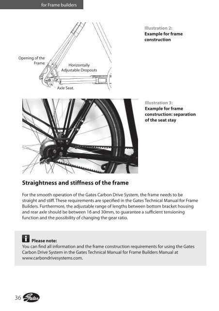
Illustration 3:<br />
Example for frame<br />
construction: separation<br />
of the seat stay<br />
Straightness and stiffness of the frame<br />
For the smooth operation of the <strong>Gates</strong> Carbon Drive System, the frame needs to be<br />
straight and stiff. These requirements are specified in the <strong>Gates</strong> Technical Manual for Frame<br />
Builders. Furthermore, the adjustable range of lengths between bottom bracket housing<br />
and rear axle should be between 16 and 30mm, to guarantee a sufficient tensioning<br />
function and the possibility of changing the gear ratio.<br />
Please note:<br />
You can find all information and the frame construction requirements for using the <strong>Gates</strong><br />
Carbon Drive System in the <strong>Gates</strong> Technical Manual for Frame Builders Manual at<br />
www.carbondrivesystems.com.<br />
36


