JCSS - FGG-KM
JCSS - FGG-KM
JCSS - FGG-KM

You also want an ePaper? Increase the reach of your titles
YUMPU automatically turns print PDFs into web optimized ePapers that Google loves.
<strong>JCSS</strong> Workshop on Reliability Based Code Calibration<br />
Reliability based life cycle design and maintenance planning<br />
Asko Sarja Postal address: Email and tel.<br />
Technical Research<br />
Centre of Finland,<br />
VTT Building and Transport<br />
P.O. Box 1803<br />
FIN-02044 VTT<br />
Espoo<br />
Finland<br />
asko.sarja@vtt.fi<br />
+358 9 456 4120<br />
Abstract<br />
The whole life principle has been introduced into design and management of<br />
structures during last years, and this development process is getting increasing<br />
interest in practice of structural engineers. The structural engineers have to create<br />
and learn new skills in order to achieve a capability for life cycle design and<br />
predictive life cycle management. These skills include new models for design and<br />
management process, new durability, performance and service life models of<br />
materials and structures, and new reliability based calculation methods, which can be<br />
applied controlling the safety over the entire service life of structures.<br />
Current standards are serving requirements for reliability, which is expressed as<br />
reliability index. However we must state, that also reliability is time depending, and<br />
has to be treated in calculations as a time dependent parameter. Also the required<br />
minimum value of reliability index should be defined separately and differently for a<br />
new structure and for an assessment of reliability and residual service life of existing<br />
structures. The new structures thus should own a specific safety margin for<br />
degradation. This safety margin should be optimised for whole life in order to<br />
minimise the costs of required repair works and to maximise the performance and<br />
serviceability of structures.<br />
Keywords: Whole life, life cycle design, life cycle management, maintenance,<br />
performance, service life, limit states, statistical method, lifetime safety factor<br />
method, degradation models, degradation safety margin<br />
1 Introduction<br />
The sustainability of built environment can in short be defined as thinking over<br />
generations. Sustainability includes social aspects (welfare, health, safety,<br />
aesthetics), economic aspects, functional aspects (usability for changing demands),<br />
technical aspects (serviceability, durability, reliability) and ecological aspects<br />
(consumption of natural resources like energy, raw materials and water, pollution of<br />
air, water and soil, waste production and impact in bio-diversity), all treated over the<br />
entire life cycle of the built facilities. The life cycle design and maintenance planning<br />
of structures is a key issue for sustainable results. It can be claimed that a built<br />
facility can only be as good as its design.<br />
Traditionally design has concentrated on the construction phase of optimising<br />
construction costs and short-term performance. Sustainable development gives rises<br />
to a need for integrated life cycle design, where all solutions are optimised for the<br />
1
<strong>JCSS</strong> Workshop on Reliability Based Code Calibration<br />
entire design service life of the building. Resistance design is expanded into<br />
durability design to include time as a new dimension in the design calculations<br />
The core competence and working area of structural engineers is the design of<br />
structures for sustainability over their life cycles. This field will here be referred to as<br />
integrated life cycle design. This means that the structural design process must be<br />
renewed. Furthermore, new methodologies and calculation methods must be<br />
adopted, e.g., from mathematics, physics, systems engineering and other natural<br />
and engineering sciences. However, we have to keep in mind the need of strong<br />
systematic, transparency and simplicity of the design process and its methods in<br />
order to keep the multiple issues under control and to avoid excessive design work.<br />
A new model of integrated life cycle design includes a framework for integrated<br />
structural life cycle design, a description of the design process and its phases,<br />
special life cycle design methods regarding different aspects like life cycle economy,<br />
life cycle environmental impact, design for reuse and recycling, service life design,<br />
durability design, multiple requirement optimisation and multiple requirement<br />
decision-making.<br />
Operation, maintenance and renewal of the built facilities is another key issue for life<br />
cycle sustainability. Rules and plans of operation and maintenance are fed by<br />
designs when the relevant information is transferred from design into maintenance<br />
system. An advanced operation and maintenance model of infrastructure facilities<br />
includes continuous condition assessment, predictive modelling of performance,<br />
durability and reliability of the facility, maintenance and repair planning and decision<br />
making procedure regarding to alternative maintenance and repair actions.<br />
The need of a reliability based specific design for lifetime performance and service is<br />
very high for civil engineering structures like bridges, harbours, roads, railways etc.<br />
are often very massive and their target service life is long. Their repair works under<br />
use are difficult. Their life cycle quality is tied to high durability and easy<br />
maintainability during use. Also many buildings include parts like foundations and<br />
envelop, which are working in severe conditions.<br />
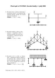
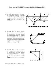
Lifetime performance design is an essential core of the integrated life cycle design.<br />
An overview of this design process and methodology is presented in fig. 1.<br />
2
<strong>JCSS</strong> Workshop on Reliability Based Code Calibration<br />
0. Design Process and Methods<br />
01. Integrated structural design and its applications<br />
1. Design for Performance<br />
1.1 Functional design of<br />
structural system and<br />
components<br />
1.2 Design for flexibility in<br />
use and in changes of<br />
the use<br />
1.3 Hygrothermal design of<br />
structures<br />
1.4 Detailed design of<br />
structures<br />
1.5 Maintenance and repair<br />
design<br />
2. Design for Economy<br />
2.1 Economic life cycle<br />
design of<br />
structural system and<br />
components<br />
5. Control of Requirements<br />
and Specifications<br />
5.1 Multiple Criteria<br />
Optimisation and Decision<br />
Making<br />
5.2 Service Life Planning of<br />
structures<br />
5.3 Integrated design<br />
documentation<br />
4. Design for Health and<br />
Comfort<br />
4.1 Health aspects in<br />
design<br />
3. Design for Ecology<br />
3.1 Design for Energy<br />
Economy<br />
3.2 Calculation of<br />
environmental<br />
burdens at the<br />
manufacturing and<br />
construction<br />
3.3 Design for reuse<br />
and recycling<br />
Fig. 1. Modules of the Integrated Life Cycle Design of buildings (Sarja 2000).<br />
2 Reliability based lifetime design<br />
2.1 Principle and methodology<br />
The role of durability design is important in life cycle design. The objective of<br />
durability design is to ensure that the specified target service life can be achieved in<br />
each working environment of the structure.<br />
3
<strong>JCSS</strong> Workshop on Reliability Based Code Calibration<br />
In ordinary design the durability for ordinary service life, generally for 50 years, is<br />
taken into account through the structural detailing rules found in norms, standards<br />
and design manuals. When using a target service life other than 50 years separate<br />
service life design calculations are needed. For these specific purposes statisticallybased<br />
service life design methods can be used to produce specific detailing rules<br />
and model designs which then can be applied for similar specific cases. Statisticallybased<br />
life cycle design can also be applied in the product development of<br />
prefabricated structural units.<br />
The detailed durability design procedure is as follows (Sarja and Vesikari 1996,<br />
Sarja 2000, Sarja 2002):<br />
1 specification of the target service life and design service life<br />
2 analysis of environmental loads onto structures<br />
3 identification of durability factors and degradation mechanisms<br />
4 selection of a durability calculation model for each degradation mechanism<br />
5 calculation of durability parameters using available calculation models<br />
6 possible updating of the calculations of the ordinary mechanical design (e.g.<br />
own weight of structures)<br />
7 transfer of the durability parameters into the final design<br />
2.2 Statistical design<br />
The simplest mathematical model for describing the 'failure' event comprises a load<br />
variable S and a response variable R. In principle the variables S and R can be any<br />
quantities and expressed in any units. The only requirement is that they are<br />
commensurable. Thus, for example, S can be a weathering effect and can be the<br />
capability of the surface to resist the weathering effect without unacceptably large<br />
visual damage or loss of the reinforcement concrete cover.<br />
If R and S are independent of time, the 'failure' event can be expressed as<br />
follows<br />
{failure} = {R < S} (1)<br />
The failure probability Pf is now defined as the probability of that 'failure':<br />
Pf = P{R
<strong>JCSS</strong> Workshop on Reliability Based Code Calibration<br />
The determination of the function Pf(t) according to the Equation 3a is<br />
mathematically difficult. That is why R and S are considered to be stochastic<br />
quantities with time-dependent or constant density distributions. By this means the<br />
failure probability can usually be defined as:<br />
Pf(t) = P{R(t)
<strong>JCSS</strong> Workshop on Reliability Based Code Calibration<br />
safety factor method is analogous with the static limit state design. A comparison of<br />
static limit state design and durability limit state design is presented in Table 1. It can<br />
be stated that durability design using the lifetime safety factor method is related to<br />
controlling the risk of falling below the target service, while static limit state design is<br />
related to controlling the reliability of the structure against failure under external<br />
mechanical loading.<br />
The lifetime safety factor method is always combined with static or dynamic design<br />
and aims to control the service life, while static and dynamic design controls the<br />
loading capacity.<br />
Table 1. Comparison of static limit state method and lifetime safety factor method.<br />
Static limit state design<br />
1. Strength class<br />
2. Target strength<br />
3. Characteristic strength ( 5 % fraktile)<br />
4. Design strength<br />
5. Partial safety factors of materials strength<br />
6. Partial safety factors of static loads<br />
7. Limit states of serviceability and<br />
ultimate states<br />
Lifetime safety factor method<br />
1. Service life class<br />
2. Target service life<br />
3. Characteristic service life (5% fraktile)<br />
4. Design service life<br />
5. Partial safety factors of service life<br />
6. Partial safety factors of environmental<br />
loads<br />
7. Durability limit states of serviceability and<br />
ultimate states.<br />
2.3.1 Limit states<br />
The lifetime safety factor design procedure is somewhat different for structures<br />
consisting of different materials, although the basic design procedure is the same for<br />
all kinds of materials and structures. Limit states can be the same as in statical<br />
design, but some generalised limit states, including e. g. visual or functional limit<br />
states, can be defined. In this way the principle of multiple requirements, which is<br />
essential for integrated life cycle design, can be introduced.<br />
2.3.2 Design life<br />
Design life is a specified time period, which is used in calculations. Ordinary design<br />
life is 50 years (CEN 1991) for buildings and 100 years for civil engineering<br />
structures. In special cases even longer design life cycles can be used. However,<br />
after 50 years the effect of increased design life cycle is quite small and it can be<br />
estimated as the residual value at the end of the calculation life cycle. Temporary<br />
structures are designed for a shorter design life, which will be specified in each<br />
individual case. The following classification of design life of ENV 1991-1 is presented<br />
in Table 2.<br />
6
<strong>JCSS</strong> Workshop on Reliability Based Code Calibration<br />
Table 2. Classification of ENV 1991-1 for design life of structures.<br />
Class 1: 1–5 years<br />
Special case temporary buildings<br />
Class 2: 25 years<br />
Temporary buildings, e. g. stores<br />
buildings, accommodation barracks<br />
Class 3: 50 years<br />
Ordinary buildings<br />
Class 4: 100 years<br />
Special buildings, bridges and other<br />
infrastructure buildings or where more<br />
accurate calculations are needed, for<br />
example, for safety reasons<br />
Class 5: over 100 years<br />
Special buildings e. g. monuments,<br />
very important infrastructure buildings<br />
2.3.3 Procedure<br />
The lifetime factor design procedure is as follows:<br />
1 Specification of target service life and design service life<br />
2 Analysis of environmental loads onto structures<br />
3. Identification of durability factors and degradation mechanisms<br />
4 Selection of a durability calculation model for each degradation mechanism<br />
5 Calculation of durability parameters using available calculation models<br />
6 Possible updating of calculations of the ordinary mechanical design (e.g. own<br />
weight o structures)<br />
6 Transfer of durability parameters into final design<br />
2.3.4 Reliability calculations<br />
The design service life is determined by formula (Sarja and Vesikari 1996, Sarja<br />
2002):<br />
td = t k /γt >= tg (5)<br />
where td is the design service life,<br />
t k the characteristic service life<br />
γt the lifetime safety factor, and<br />
tg the target service life.<br />
7
<strong>JCSS</strong> Workshop on Reliability Based Code Calibration<br />
Using the lifetime safety factor, the requirement of target service life (corresponding<br />
to a maximum allowable failure probability) is converted to the requirement of mean<br />
service life.<br />
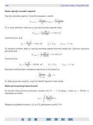
The mean service life is approximated by service life models which show the<br />
crossing point of the degradation curve with the limit state of durability (Fig. 3). The<br />
mean service life evaluated by the service life model must be greater than or equal to<br />
the design service life, which is the product of the lifetime safety factor and target<br />
service life.<br />
µ(tL) > td (6)<br />
td = γt tg (7)<br />
where<br />
td is the design service life.<br />
Fig. 3. The meaning of lifetime safety factor in a performance problem.<br />
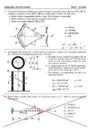
The lifetime safety factor depends on the maximum allowable failure probability. The<br />
lifetime safety factor also depends on the form of service life distribution. Fig. 4.<br />
illustrates the meaning of lifetime safety factor when the design is done according to<br />
the performance principle. The function R(t) – S is called the safety margin.<br />
8
<strong>JCSS</strong> Workshop on Reliability Based Code Calibration<br />
Fig. 4. The meaning of the lifetime safety factor.<br />
Performance behaviour can always be translated into degradation behaviour. By<br />
definition, degradation is a decrease in performance. The transformation is<br />
performed by the following substitutions:<br />
R0 – R(t) = D(t) (8)<br />
R0 – S = Dmax<br />
or<br />
R 0 – R min = D max<br />
Let us consider that the degradation function is of the following form:<br />
µ(D(t)) = a.tn (9)<br />
where µ(D(t)) is the mean of degradation,<br />
a the constant coefficient,<br />
t time, and<br />
n the exponent.<br />
The exponent n may in principle vary between -∞ and +∞.<br />
The coefficient a is fixed when the mean service life is known:<br />
Dmax<br />
a = (10)<br />
n<br />
µ () tL<br />
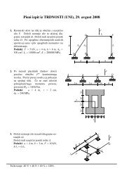
Degradation is assumed to be normally distributed around the mean. It is also<br />
assumed that the standard deviation of D is proportional to the mean degradation,<br />
the coefficient of variation being constant, νD. Fig. 5 shows the degradation as a<br />
function of tn .<br />
9
<strong>JCSS</strong> Workshop on Reliability Based Code Calibration<br />
Fig. 5. The meaning of lifetime safety factor in a degradation problem.<br />
The index β of standard normal distribution at tg is:<br />
Dmax<br />
- Dg<br />
1 æD<br />
max<br />
ö<br />
β = = × 1<br />
νDDg ν<br />
- D<br />
çè D<br />
g<br />
÷ ø<br />
(11)<br />
where Dmax is the maximum allowable degradation,<br />
Dg the mean degradation at tg, and<br />
νD the coefficient of variation of degradation.<br />
From Fig. 5. we get:<br />
( γ<br />
t<br />
t<br />
g)<br />
n<br />
( t<br />
g )<br />
D<br />
max n<br />
= = γ<br />
t<br />
(12)<br />
D<br />
g<br />
n<br />
By assigning this to equation (11) we obtain:<br />
γ t = (β. νD +1)1/n (13)<br />
The lifetime safety factor depends on β (respective to the maximum allowable failure<br />
probability at tg), the coefficient of variation of D and the exponent n. Thus the<br />
lifetime safety factor is not directly dependent on tg.<br />
10
<strong>JCSS</strong> Workshop on Reliability Based Code Calibration<br />
2.4 Service life design of concrete structures with safety factor<br />
method<br />
2.4.1 Degradation factors and their structural effects<br />
The following degradation factors are most commonly dealt with:<br />
1. corrosion due to chloride penetration<br />
2. corrosion due to carbonation<br />
3. mechanical abrasion<br />
4. salt weathering<br />
5. surface deterioration<br />
6. frost attack<br />
Additionally there exist some internal degradation processes, such as alkalineaggregate<br />
reaction, are not treated here as they can be solved by a proper selection<br />
of raw materials and an appropriate design of concrete mix.<br />
Degradation factors affect either the concrete or the steel or both. Usually<br />
degradation takes place on the surface zone of concrete or steel, gradually<br />
destroying the material.<br />
The main structural effects of degradation in concrete and steel are the following:<br />
1. Loss of concrete leading to reduced cross-sectional area of the concrete.<br />
2. Corrosion of reinforcement leading to reduced cross-sectional area of steel<br />
bars.<br />
Corrosion may occur at cracks at all steel surfaces, assuming that the corrosion<br />
products are able to leach out through the pores of the concrete (general corrosion in<br />
wet conditions). splitting and spalling of the concrete cover due to general corrosion<br />
of reinforcement, leading to a reduced cross-sectional area of the concrete, to a<br />
reduced bond between concrete and reinforcement and to visual unfitness.<br />
2.4.2 Design procedure<br />
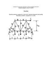
2.4.2.1 Phases of design<br />
General phases of design are as follows:<br />
1 specification of the target service life and design service life<br />
2 analysis of environmental effects<br />
3 identification of durability factors and degradation mechanisms<br />
4 selection of a durability calculation model for each degradation mechanism<br />
5 calculation of durability parameters using available calculation models<br />
6 possible updating of the calculations of the ordinary mechanical design<br />
7 transfer of the durability parameters into the final design<br />
11
<strong>JCSS</strong> Workshop on Reliability Based Code Calibration<br />
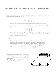
The phases are presented as a schedule in Fig. 6.<br />
ORDINARY<br />
MECHANICAL DESIGN<br />
Dimensioning of the<br />
structure by ordinary<br />
design methods<br />
- static<br />
(- fatique)<br />
(- dynamic)<br />
Results:<br />
- preliminary dimensions<br />
of the structure<br />
- amount and locations<br />
of reinforcements<br />
- strength of concrete<br />
FINAL DESIGN<br />
Alternative 1<br />
(separated design method):<br />
- integration of the results<br />
of ordinary mechanical<br />
design and durability<br />
design<br />
Alternative 2<br />
(combined design method):<br />
- mechanical redimensioning<br />
of the structure taking into<br />
account the durability<br />
parameters<br />
Checking of final results<br />
and possible feedback<br />
DURABILITY DESIGN<br />
• Determination of target<br />
service life and design<br />
service life<br />
• Analysis of environmental<br />
effects<br />
• Identification of degradation<br />
mechanisms<br />
• Selection of durability<br />
models for degradation<br />
mechanisms<br />
• Determination of durability<br />
parameters, e.g.<br />
- depth of deterioration<br />
of concrete and<br />
corrosion of<br />
reinforcement<br />
- concrete cover<br />
- diameter of rebars<br />
Factors to be taken into<br />
account, e.g.:<br />
- strength of concrete<br />
- permeability of concrete<br />
- type of cement<br />
- curing method<br />
- type of reinforcement<br />
- structural dimensions<br />
Fig. 6. Flow chart of the durability design procedure.<br />
2.4.2.2 Description of the phases of the durability design<br />
Phase1: Specification of target service life and design service life<br />
The target service life is defined corresponding to the requirements given in common<br />
regulations, codes and standards in addition to possible special requirements of the<br />
client. Typical classes of service life are 10, 25, 50, 75, 100 etc. years. The safety<br />
classification of durability design is presented in Table 3.<br />
The design service life is determined by formula:<br />
td = γt . tg (10)<br />
where td is the design service life,<br />
γt<br />
the lifetime safety factor, and<br />
12
<strong>JCSS</strong> Workshop on Reliability Based Code Calibration<br />
tg<br />
the target service life.<br />
Table 3.10. Safety classification of durability design and the corresponding safety factors.<br />
Table 3. Values of central lifetime safety factors-<br />
Limit state Safety class of durability design Separated design Combined design<br />
Lifetime<br />
safety<br />
factor<br />
Load and Lifetime<br />
safety<br />
factor<br />
Load<br />
Ultimate<br />
limit state<br />
Serviceability<br />
limit<br />
state<br />
material<br />
safety<br />
factors<br />
material<br />
safety<br />
factors<br />
γ t<br />
γ t<br />
1. Serious social, economic or<br />
ecological consequences of a<br />
mechanical failure. 3.3 normal 4 2.5 normal 4<br />
2. Consequences of a<br />
γ<br />
mechanical failure are not<br />
g 1.3 5<br />
serious. 2.9 normal 4 2.2<br />
γ p 1.38<br />
γ c 1.4<br />
γ s 1.13<br />
1. Noticeable consequences and<br />
considerable repair costs.<br />
2.5 – 1.9 –<br />
2. Non-noticeable consequences<br />
and repair costs. 1.9 – 1.5 –<br />
and<br />
Phase 2: Analysis of environmental loads<br />
The analysis of environmental effects includes identification of the climatic conditions<br />
such as temperature and moisture variations, rain, condensation of moisture,<br />
freezing, solar radiation and air pollution, and the identification of geological<br />
conditions such as the location of ground water, possible contact with sea water,<br />
contamination of the soil by aggressive agents like sulphates and chlorides. Manmade<br />
actions such as salting of roads, abrasion by traffic etc. must also be identified.<br />
Phase 3: Identification of degradation factors and degradation mechanisms<br />
Based on the environmental effect analysis the designer identifies the degradation<br />
factors to which the structure will most likely be subjected. Some kind of degradation<br />
process is usually assumed to take place in both the concrete and the reinforcement.<br />
Phase 4: Selection of durability models for each degradation mechanism<br />
A designer must determine which degradation factors are decisive for service life..<br />
The models presented in the report may be applied in these evaluations. In concrete<br />
structures exposed to normal outdoor conditions the effects of degradation<br />
mechanisms can be classified into the following structural deterioration mechanisms:<br />
1 corrosion of reinforcement at cracks, causing a reduction in the cross-sectional<br />
area of steel bars.<br />
2 surface deterioration or frost attack, causing a reduction in the cross-sectional area<br />
of concrete.<br />
Phase5: Calculation of durability parameters through calculation models<br />
13
<strong>JCSS</strong> Workshop on Reliability Based Code Calibration<br />
Damage is determined using the design service life, td, as time. Selected calculation<br />
models are presented in the appendix of the TC 130-CSL report (Sarja and Vesikari,<br />
1996).<br />
Phase 6: Possible updating of calculations in ordinary mechanical design<br />
Some durability parameters may influence the mechanical design. An increase in<br />
concrete dimensions, increases the dead load, thus increasing the load effects on<br />
both the horizontal and vertical structures.<br />
Phase 7: Transfer of durability parameters to the final design<br />
The parameters of the durability design are listed and transferred to the final design<br />
phase for use in the final dimensioning of the structure.<br />
Phase 8: Final design<br />
8.1 Separated design method<br />
In the separated design method the mechanical design and the durability design are<br />
separated. The ordinary structural design (phase1) produces the mechanical safety<br />
and serviceability parameters whereas the durability design (phase 2) produces the<br />
durability parameters. Both of these groups of parameters are then combined in the<br />
final design of the structure.<br />
8.2 Combined design method<br />
In the combined design method mechanical design is carried out taking into account<br />
the results of the durability design and the required safety at the end of service life.<br />
The combined method is especially suited to degradation mechanisms which directly<br />
affect the loadbearing capacity or the mechanical serviceability of structures.<br />
2.4.3 Degradation models<br />
A designer must determine which degradation factors are decisive for service life.<br />
Preliminary evaluations of rates of degradation for different factors may be<br />
necessary. The models presented in the report may be applied in these evaluations.<br />
In concrete structures exposed to normal outdoor conditions the effects of<br />
degradation mechanisms can be classified into the following structural deterioration<br />
mechanisms:<br />
1. Corrosion of reinforcement at cracks in the concrete, causing a reduction in<br />
the cross-sectional area of steel bars.<br />
2. Surface deterioration or frost attack, causing a reduction in the cross-sectional<br />
area of concrete.<br />
The damages are determined using the design service life, t d , as time. Selected<br />
calculation models are presented in the appendix of the TC 130-CSL report (Sarja<br />
and Vesikari, 1996).<br />
14
<strong>JCSS</strong> Workshop on Reliability Based Code Calibration<br />
3 Reliability based maintenance<br />
3.1 Reliability based and predictive life cycle management system<br />
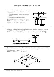
A schedule for a predictive life time maintenance and management system called<br />
“LIFECON”, which is under development in a project of EU Growth program, is<br />
presented in Fig. 7. (EU Growth project “Lifecon”, Work Description). The objectives<br />
of Lifecon project is a system, which will make it possible to change the facility<br />
maintenance, management and operation of civil infrastructures and buildings from a<br />
reactive approach into a predictive and performance based life cycle approach. This<br />
objective will be concretised through an open and generic model of “Integrated and<br />
Predictive Life cycle Maintenance and management planning System (LMS)”. This<br />
system description will include the framework, process, performance and service life<br />
models and calculation methods and condition assessment protocol model of the<br />
“Lifecon LMS” (Life Cycle Management) system. This system is open, generic and<br />
predictive in its character; thus it can be applied for different kinds of structures and<br />
objects, and with different technical specifications.<br />
15
<strong>JCSS</strong> Workshop on Reliability Based Code Calibration<br />
Fig. 7. A schedule of content of “Lifecon LMS” (Sarja, Asko (co-ordinator), “Lifecon”,<br />
Work Description).<br />
WP2: Life Cycle<br />
Performance based<br />
Optimisation and<br />
Decision- Making.<br />
1. Performance<br />
Systematic<br />
2. Mathematical Life<br />
Cycle Performance<br />
and Reliability Models<br />
3. QFD methods for<br />
analysis of users<br />
requirements<br />
4. Multi-Attribute<br />
Optimisation and<br />
Decision Making<br />
WP3.Condition<br />
Assessment Protocol and<br />
Prediction of Residual<br />
Service Life<br />
1.Condition Assessment<br />
Protocol<br />
2. Service Life calculation<br />
models<br />
WP1: Predictive and<br />
Integrated Life Cycle<br />
Management System (LMS)<br />
Goal setting:<br />
1. Life cycle economy<br />
(LCC)<br />
2. Life Cycle Ecology<br />
(LCE)<br />
3. Life Cycle Performance<br />
(LCP)<br />
4. Safety, Health and<br />
Comfort (SHC)<br />
Management:<br />
1. Ranking of Priorities<br />
and boundaries of LCC,<br />
LCE , LCP and SHC<br />
2. Multi-Attribute<br />
Optimisation and<br />
Decision Making<br />
3. Plan for repairs and<br />
renewals<br />
4. Structural Facility<br />
Database on Condition and<br />
Condition Prediction<br />
WP6: European Validation<br />
of Results<br />
1. Validation plan of<br />
LIFECON for each<br />
country/location/object<br />
2. Documenting the<br />
selected structures for<br />
each country<br />
3. Report on opinions of<br />
practitioners<br />
4. Validation and Audit<br />
report for each<br />
country/location/object<br />
WP4: Environmental Exposure<br />
Module<br />
1. Definition of necessary<br />
environmental degradation<br />
load parameters.<br />
2. Instructions for quantitative<br />
classification<br />
of<br />
environmental degradation<br />
loads onto structures<br />
3. National reports on GIS<br />
based national exposure<br />
modules quantitative<br />
environmental degradation<br />
loads<br />
WP5: Maintenance and<br />
Retrofitting Systems<br />
1. Qualitative description and<br />
classification of repair<br />
materials and systems<br />
2. Quantitative and classified<br />
information on RAMS and<br />
LCE for repair materials<br />
and systems<br />
WP7: Dissemination of Results and Project Management:<br />
1. Annual Workshops and Plenary<br />
2.Biannual meetings of the Leading Group<br />
3. Reports internally and to EU Commission<br />
16
<strong>JCSS</strong> Workshop on Reliability Based Code Calibration<br />
3.2 Reliability of existing structures<br />
Similar reliability calculations to the life cycle design, either directly statistical or applying lifetime<br />
safety factor method, can be applied in maintenance and repair planning. Referring to the descriptions<br />
above in chapter 2, we can conclude, that most often the reliability index is decreasing with the time.<br />
However, currently the same reliability indexes with the design of new structures are applied also in<br />
reliability analysis of existing structures, as shown in Table 4. This leads in most cases to a conflict<br />
between reality and theory as soon as some degradation has been observed.<br />
Table 4. Target Reliability Index β for existing structures (ISO/DIS Nr 13822).<br />
Limit State Reliability Index β Reference Period<br />
Serviceablitiy<br />
Fatique<br />
Consequences of<br />
failure<br />
Reversible 0,0<br />
Irreversible 1,5<br />
Inspectable 2,3<br />
Not inspectable 3,1<br />
Very Low 2,3<br />
Low 3,1<br />
Medium 3,8<br />
High 4,3<br />
Intended remaining service lfie<br />
Minimum period for safety<br />
(e.g. 50 years)<br />
3.3 Conclusions and proposals<br />
The following conclusions and proposals can be drawn:<br />
1. Current reliability theory and corresponding standards are not systematically taking into<br />
account the effects of gradual degradation of structures, which usually will identified<br />
during the condition assessments as a part of maintenance and repair planning of<br />
structures.<br />
2. The requirements for reliability index should be developed into a life time principle,<br />
having first a degradation margin, which then could be used until the minimum<br />
requirement of existing structures.<br />
3. The degradation margin should be optimised for each material under different<br />
environmental load classes in order to achieve an optimal lifetime performance and repair<br />
actions.<br />
4. The required reliability level of existing structures, which currently in fact is unknown,<br />
should be defined basing on theoretical analysis and optimisation, as well as on final<br />
decision of international standardisation bodies.<br />
5. The residual time of adequate performance and service life could be estimated and<br />
predicted during the use applying updated performance and degradation parameters after<br />
each condition assessment. In this residual service life prediction could be applied the<br />
minimum requirements for reliability indexes of existing structures.<br />
17
<strong>JCSS</strong> Workshop on Reliability Based Code Calibration<br />
Literature<br />
1. Sarja, Asko & Vesikari, Erkki (Editors). Durability design of concrete structures.<br />
RILEM Report of TC 130-CSL. RILEM Report Series 14. E&FN Spon, Chapman<br />
& Hall, 1996. 165 pp.<br />
2. SARJA, Asko, Development towards practical instructions of life cycle design in<br />
Finland. Proceedings of the RILEM/CIB/ISO International Symposium: „Integrated<br />
Life-Cycle Design of Materials and Structures, ILCDES 2000“. RILEM<br />
Proceedings PRO 14, pp. 57-62. RIL-Association of Finnish Civil Engineers,<br />
2000.<br />
3. SARJA, Asko, Integrated Life Cycle Design of Structures. 142 pp.Spon Press,<br />
London 2002. ISBN 0-415-25235-0.<br />
4. Sarja, Asko (co-ordinator), EU Growth Project: „Lifecon“: Life cycle management<br />
of concrete infrastructures for improved sustainability, 2001-2003. Work<br />
Description, 2001. 74 pp.<br />
18