JD & KD Series Ultra-Capacity Float & Thermostatic Steam Traps
JD & KD Series Ultra-Capacity Float & Thermostatic Steam Traps
JD & KD Series Ultra-Capacity Float & Thermostatic Steam Traps

Create successful ePaper yourself
Turn your PDF publications into a flip-book with our unique Google optimized e-Paper software.
<strong>JD</strong> & <strong>KD</strong> <strong>Series</strong> <strong>Ultra</strong>-<strong>Capacity</strong> <strong>Float</strong> & <strong>Thermostatic</strong> <strong>Steam</strong> <strong>Traps</strong><br />
Ductile Iron for Horizontal Installation, with <strong>Thermostatic</strong> Air Vent<br />
For Pressures to 21 bar...Capacities to 64 400 kg/h<br />
C<br />
C<br />
P<br />
C<br />
P<br />
P<br />
HH<br />
H<br />
HH<br />
H<br />
HH<br />
H<br />
S<br />
S<br />
P<br />
S<br />
P<br />
P<br />
HH2<br />
HH1<br />
HH2<br />
HH1<br />
H<br />
HH2<br />
HH1<br />
H<br />
HS<br />
S<br />
S<br />
B<br />
M<br />
B<br />
M B<br />
M<br />
T<br />
BT<br />
M<br />
BT<br />
B M<br />
M<br />
T<br />
T<br />
T<br />
<strong>Steam</strong> <strong>Traps</strong><br />
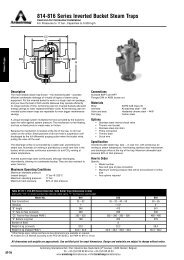
Description<br />
The simple, yet rugged, ductile iron construction of the <strong>JD</strong> & <strong>KD</strong> <strong>Series</strong><br />
<strong>Ultra</strong>-<strong>Capacity</strong> F&T steam traps offers long, trouble-free service. All floats,<br />
valves and seats, and lever mechanisms are constructed of stainless steel.<br />
The integral thermostatic air vent is a balanced-pressure phosphor bronze<br />
bellows caged in stainless steel. It is designed especially for heavy-duty<br />
industrial applications where highly efficient, uninterrupted service is<br />
essential. This balanced-pressure-type air vent will respond to the<br />
pressure-temperature curve of steam at any pressure from zero to 21 bar.<br />
Thus – up to 21 bar – air is vented at slightly below steam temperature.<br />
Maximum Operating Conditions<br />
Maximum allowable pressure (vessel design):<br />
Model <strong>JD</strong> & <strong>KD</strong> 21 bar @ 343°C<br />
Maximum operating pressure:<br />
Model 15-<strong>JD</strong>: 1 bar saturated steam<br />
Model 20-<strong>JD</strong>: 1,4 bar saturated steam<br />
Model 30-<strong>JD</strong>: 2 bar saturated steam<br />
Model 75-<strong>JD</strong>: 5 bar saturated steam<br />
Model 125-<strong>JD</strong>: 8,5 bar saturated steam<br />
Model 175-<strong>JD</strong>: 12 bar saturated steam<br />
Model 250-<strong>JD</strong>: 17 bar saturated steam<br />
Model 300-<strong>JD</strong>: 21 bar saturated steam<br />
Model 30-<strong>KD</strong>: 2 bar saturated steam<br />
Model 50-<strong>KD</strong>: 3,5 bar saturated steam<br />
Model 300-<strong>KD</strong>: 21 bar saturated steam<br />
Maximum back pressure: 99% of inlet pressure<br />
Maximum operating temperature bellows: 217°C<br />
Connections<br />
Screwed BSPT and NPT<br />
Flanged DIN or ANSI (screw on)<br />
Materials<br />
Body and cap: ASTM A395 ductile iron<br />
Internals: All stainless steel – 304<br />
Valve(s) and seat(s): Stainless steel<br />
Drain plug:<br />
Carbon steel<br />
<strong>Thermostatic</strong> air vent: Stainless steel and bronze with phosphor<br />
bronze bellows, caged in stainless steel<br />
Options<br />
• Integral vacuum breaker 10 bar maximum. Add suffix VB to<br />
model number<br />
• No internal thermostatic air vent for liquid drainer service. Add<br />
suffix LD to model number<br />
• Integral flash release for syphon drainage service. Add suffix CC<br />
to model number<br />
• Armored gauge glass 17 bar @ 218°C<br />
Specification<br />
<strong>Float</strong> and thermostatic steam trap, type ... in ductile iron, with thermostatic<br />
air vent. Maximum allowable back pressure 99% of inlet pressure.<br />
D<br />
D<br />
D<br />
<strong>Series</strong> <strong>JD</strong> & <strong>KD</strong> Cap <strong>Series</strong> <strong>JD</strong>, F&T Shown <strong>Series</strong> <strong>KD</strong>, F&T Shown<br />
How to Order<br />
Pressure<br />
Special Configurations<br />
Condensate controller with flash release for syphon drainage and/or<br />
cascade service. The condensate controller (CC) configuration was<br />
developed especially to meet very large capacity needs in applications<br />
where condensate must be lifted from the drain point to the trap. Under<br />
such conditions – often referred to as syphon drainage – the reduction in<br />
pressure that occurs when the condensate is elevated causes a portion of<br />
the condensate to flash into steam. Ordinary traps, unable to differentiate<br />
between flash steam and live steam, close and impede drainage.<br />
The <strong>JD</strong> & <strong>KD</strong> <strong>Series</strong> condensate controllers (CC) are equipped with a fixed,<br />
restricted orifice near the top of the body to bleed off the flash steam (and<br />
all air present). This permits the trap to function properly on condensate.<br />
Liquid drainer with back vent for exceptionally high-capacity<br />
drainage of liquid from gas under pressure. The liquid drainer (LD)<br />
configuration was developed to meet very large capacity needs in draining<br />
water and other liquids from air or other gases under pressure. To prevent<br />
air or gas binding, the access port in the top of the body serves as a back<br />
vent connection to the equipment being drained. For capacity data, see<br />
pages LD-439 and LD-462 or consult your Armstrong Representative.<br />
All dimensions and weights are approximate. Use certified print for exact dimensions. Design and materials are subject to change without notice.<br />
D<br />
D<br />
Model<br />
D<br />
Connection<br />
Size<br />
Option<br />
75 <strong>JD</strong> 8 VB<br />
15<br />
20<br />
30<br />
75<br />
125<br />
175<br />
250<br />
300<br />
30<br />
50<br />
300<br />
<strong>JD</strong><br />
<strong>KD</strong><br />
8 = DN50<br />
8 = DN50<br />
10 = DN65<br />
12 = DN80<br />
VB = Vacuum Breaker<br />
LD = Liquid Drainer<br />
CC = Condensate<br />
Controller<br />
GG = Gauge Glass<br />
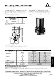
Table ST-128-1. <strong>JD</strong> and <strong>KD</strong> <strong>Series</strong> Side Inlet, Side Outlet Trap<br />
Model No. <strong>JD</strong> <strong>KD</strong><br />
Pipe Connections 50 50, 65, 80<br />
“B” Height 332 332<br />
“C” Width 246 246<br />
“H” Face-to-Face (screwed) 348 373<br />
“HH1” Inlet Face-to-Face (flanged PN40*) 420 448<br />
“HH2” Outlet Face-to-Face (flanged PN40*) 420 548<br />
“D” Bottom to CL<br />
74,6 90<br />
“M” C L to CL<br />
168 152<br />
“P” Trap top to VB top 46 46<br />
“S” (Gauge Glass width) 114 114<br />
“T” (Gauge Glass height) 222 222<br />
Weight in kg (screwed) 36,3 39,5<br />
Weight in kg (flanged PN40*) 45 49<br />
Dimensions in mm<br />
* Other flange sizes, ratings and face-to-face dimensions are available on request.<br />
All models are CE Marked according to PED (97/23/EC)<br />
ST-128<br />
Armstrong International SA • Parc Industriel des Hauts-Sarts (2 e Avenue) • 4040 Herstal • Belgium<br />
Tel.: +32 (0)4 240 90 90 • Fax: +32 (0)4 240 40 33<br />
www.armstronginternational.eu • info@armstronginternational.eu
<strong>JD</strong> & <strong>KD</strong> <strong>Series</strong> <strong>Ultra</strong>-<strong>Capacity</strong> <strong>Float</strong> & <strong>Thermostatic</strong> <strong>Steam</strong> <strong>Traps</strong><br />
Ductile Iron for Horizontal Installation, with <strong>Thermostatic</strong> Air Vent<br />
For Pressures to 21 bar...Capacities to 64 400 kg/h<br />
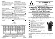
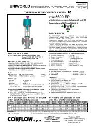
Table ST-129-1. <strong>JD</strong> <strong>Series</strong> <strong>Capacity</strong><br />
Table ST-129-2. Model 30-K8/50-<strong>KD</strong>10 <strong>Capacity</strong><br />
<strong>Capacity</strong>, kg/h<br />
15 000<br />
10 000<br />
7 000<br />
5 000<br />
4 000<br />
3 000<br />
2 500<br />
2 000<br />
1 500<br />
1-1/16<br />
7/8<br />
3/4<br />
9/16<br />
1/2<br />
7/16<br />
3/8<br />
5/16<br />
1<br />
1,5<br />
2<br />
5<br />
8,5<br />
12<br />
17<br />
20<br />
<strong>Capacity</strong>, kg/h<br />
50 000<br />
30 000<br />
25 000<br />
20 000<br />
15 000<br />
10 000<br />
700<br />
2<br />
3,5<br />
<strong>Steam</strong> <strong>Traps</strong><br />
1 000<br />
500<br />
700<br />
500<br />
400<br />
300<br />
250<br />
0,02 0,03 0,05 0,07 0,1 0,2 0,3 0,5 0,7 1 2 3 5 10 20<br />
Pressure, bar<br />
0,02 0,03 0,05 0,07 0,1 0,2 0,3 0,5 0,7 1 2 3 5 7<br />
Pressure, bar<br />
Table ST-129-3. Model 300-<strong>KD</strong>10 <strong>Capacity</strong><br />
Options<br />
Vacuum Breaker – 1/2'' NPT<br />
Many times, condensate will be retained ahead of steam traps because<br />
of the presence of a vacuum. To break a vacuum, air must be<br />
introduced into the system by means of a vacuum breaker.<br />
For maximum protection against freezing and water hammer in heating<br />
coils under modulated control, for example, vacuum breakers are<br />
recommended in conjunction with freeze protection devices.<br />
Table ST-129-2. Vacuum Breaker (dimensions in mm)<br />
Size 1/2" NPT Max. allow. pres.<br />
“B” Pipe Connections 3/8"<br />
“C” Height 30<br />
10 bar<br />
“D” Width<br />
22 Hex<br />
<strong>Capacity</strong>, kg/h<br />
100 000<br />
70 000<br />
50 000<br />
30 000<br />
25 000<br />
20 000<br />
15 000<br />
10 000<br />
7 000<br />
0,02 0,03 0,05 0,07 0,1 0,2 0,3 0,5 0,7 1 2 3 5 7 10 20 30 50 70 100<br />
Pressure, bar<br />
Table ST-129-4. Model 300-<strong>KD</strong>12 <strong>Capacity</strong><br />
12<br />
D<br />
C<br />
B<br />
<strong>Capacity</strong>, kg/h<br />
100 000<br />
70 000<br />
50 000<br />
30 000<br />
25 000<br />
20 000<br />
15 000<br />
10 000<br />
7 000<br />
0,02 0,03 0,05 0,07 0,1 0,2 0,3 0,5 0,7 1 2 3 5 7 10 20 30 50 70 100<br />
Pressure, bar<br />
12<br />
All dimensions and weights are approximate. Use certified print for exact dimensions. Design and materials are subject to change without notice.<br />
Armstrong International SA • Parc Industriel des Hauts-Sarts (2 e Avenue) • 4040 Herstal • Belgium<br />
Tel.: +32 (0)4 240 90 90 • Fax: +32 (0)4 240 40 33<br />
www.armstronginternational.eu • info@armstronginternational.eu<br />
ST-129