
You also want an ePaper? Increase the reach of your titles
YUMPU automatically turns print PDFs into web optimized ePapers that Google loves.
ä<br />
ä<br />
ä<br />
ä<br />
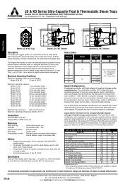
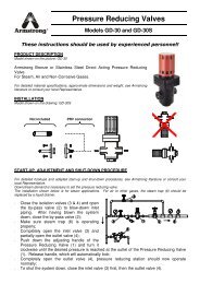
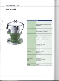
<strong>Free</strong> <strong>Floating</strong> <strong>Guided</strong> <strong>Lever</strong> <strong>Drain</strong> <strong>Traps</strong><br />
For Loads to 19 000 kg/h...Pressures to 69 bar<br />
Armstrong’s forged steel, free-floating guided lever drain traps<br />
use the same bodies, caps, lever mechanisms, valves and<br />
seats of Armstrong inverted bucket steam traps that have been<br />
proven in years of service. Elliptical floats and high leverage<br />
make it possible to open large orifices to provide adequate<br />
capacity for drain trap size and weight.<br />
The hemispherical valve, seat and leverage of the 32-LD,<br />
33-LD and 36-LD stainless steel traps are identical in design,<br />
materials and workmanship to those for saturated steam<br />
service up to 69 bar with the exception of the addition of a<br />
guidepost to assure a positive, leaktight valve closing under all<br />
conditions.<br />
Table LD-455-1. 30-LD List of Materials<br />
Model No.<br />
32-LD<br />
33-LD<br />
36-LD<br />
Valve &<br />
Seat<br />
<strong>Lever</strong>age<br />
System<br />
Stainless Steel<br />
Float Body & Cap Gasket<br />
Forged Steel<br />
ASTM A105<br />
Compressed<br />
Asbestos-free<br />
For information on special materials, consult the Armstrong Application<br />
Engineering Department.<br />
Vent<br />
LL<br />
L<br />
ä<br />
ä<br />
ä<br />
ä<br />
ä<br />
D<br />
ä<br />
ä<br />
ä<br />
ä<br />
B BB<br />
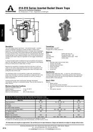
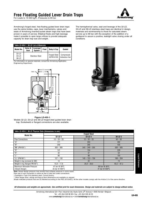
Figure LD-455-1.<br />
Models 32-LD, 33-LD and 36-LD forged steel guided lever drain<br />
trap. Socketweld or flanged connections are also available.<br />
Table LD-455-2. 30-LD Physical Data (dimensions in mm)<br />
Model No.<br />
Forged Steel<br />
32-LD † 33-LD † 36-LD †<br />
Pipe Connections 15 – 20 – 25 15 – 20 – 25 40 – 50<br />
“A” 171 203 302<br />
“B” 259 295 435<br />
"BB" (PN100*) 300 – 305 343 – 349 – 355 500 – 505<br />
“D” 141 154 229<br />
“K” 32 37 54<br />
“L” 86 98 154<br />
"LL" (PN100*) 127 – 132 145 – 153 – 159 198 – 204<br />
Weight in kg (screwed & SW) 14 22 74<br />
Weight in kg (flanged PN100*) 15,8 – 17,8 25,0 – 26,0 83,2 – 87,2<br />
Maximum Allowable Pressure<br />
41 bar @ 38°C<br />
69 bar @ 38°C<br />
(Vessel Design)<br />
35 bar @ 400°C<br />
41 bar @ 400°C<br />
Note: Vessel design pressure may exceed float collapse pressure in some cases.<br />
Pipe size of vent connection is same as that of inlet and outlet connections.<br />
† Available in Type 316 stainless steel. Consult factory.<br />
* Other flange sizes, ratings and face-to-face dimensions are available on request.<br />
Shade indicates products that are CE Marked according to the PED (97/23/EC). All the other models comply with the Article 3.3 of the same directive.<br />
Liquid <strong>Drain</strong>ers<br />
All dimensions and weights are approximate. Use certified print for exact dimensions. Design and materials are subject to change without notice.<br />
Armstrong International SA • Parc Industriel des Hauts-Sarts (2 e Avenue) • 4040 Herstal • Belgium<br />
Tel.: +32 (0)4 240 90 90 • Fax: +32 (0)4 240 40 33<br />
www.armstronginternational.eu • info@armstronginternational.eu<br />
LD-455
Fixed Pivot and Snap Action <strong>Drain</strong> <strong>Traps</strong><br />
For Loads to 1 770 kg/h...Pressures to 69 bar<br />
Continuous Flow or On-Off Float Type <strong>Drain</strong> <strong>Traps</strong><br />
Armstrong’s line of fixed lever and snap action drain traps<br />
includes two basic models available in cast iron and forged<br />
steel. The floats are light enough to handle light liquids.<br />
No. 21 – A small, high-quality, economical drain trap for use on<br />
drainage jobs where dirt and oil are not encountered. It employs<br />
a single lever with a fixed pivot.<br />
No. 21-312 – Forged steel version of the No. 21 with larger float<br />
and higher leverage.<br />
No. 71-A – Wide open, tight-shut drain trap for use where fine<br />
dirt and grit may be present or where liquid load is light. A flat<br />
spring in the leverage system holds the valve closed until the<br />
trap body is nearly full of water. Then it snaps open, washing<br />
dirt through. When the trap body is nearly empty, the spring<br />
snaps the valve shut.<br />
No. 71-315 – Forged steel version of No. 71-A.<br />
Caution: Ball float drain traps are not recommended where<br />
heavy oil, sludge or considerable dirt are encountered in lines.<br />
Under these circumstances use Armstrong inverted bucket<br />
BVSW traps.<br />
Table LD-456-1. Maximum Operating Pressures in bar for Handling Different Specific Gravity With Orifices Available in Fixed <strong>Lever</strong> and Snap Action<br />
<strong>Drain</strong> <strong>Traps</strong> (See pages LD-438 and LD-439)<br />
Model No.<br />
21-312*<br />
21<br />
96 g<br />
Float<br />
128 g<br />
Float<br />
170 g<br />
Float<br />
71-A<br />
&<br />
71-315<br />
Sp. Grav. 1,00 0,95 0,90 0,85 0,80 0,75 0,70 0,65 0,60 0,55 0,50<br />
Orifice<br />
Size (in)<br />
1/4"<br />
7/32"<br />
3/16"<br />
5/32"<br />
9/64"<br />
1/8"<br />
3/32"<br />
5/64"<br />
1/16"<br />
1/4"<br />
7/32"<br />
3/16"<br />
5/32"<br />
9/64"<br />
1/8"<br />
3/32"<br />
5/64"<br />
1/16"<br />
1/4"<br />
3/16"<br />
1/8"<br />
7/64"<br />
Maximum Operating Pressure in bar @ 38°C<br />
bar bar bar bar bar bar bar bar bar bar bar<br />
1,5<br />
1,9<br />
2,6<br />
3,8<br />
4,6<br />
5,8<br />
10,2<br />
14,0<br />
17,0<br />
2,9<br />
3,8<br />
5,1<br />
14,0<br />
16,0<br />
20,0<br />
34,0<br />
41,0<br />
41,0<br />
0,7<br />
1,4<br />
6,9<br />
14,0<br />
1,4<br />
1,8<br />
2,4<br />
3,5<br />
4,2<br />
5,4<br />
9,4<br />
13,0<br />
17,0<br />
2,7<br />
3,5<br />
4,7<br />
14,0<br />
15,0<br />
18,0<br />
32,0<br />
37,0<br />
41,0<br />
0,7<br />
1,4<br />
6,9<br />
14,0<br />
1,3<br />
1,6<br />
2,2<br />
3,2<br />
3,9<br />
4,9<br />
8,6<br />
12,0<br />
17,0<br />
2,5<br />
3,2<br />
4,4<br />
13,0<br />
14,0<br />
17,0<br />
29,0<br />
34,0<br />
41,0<br />
0,7<br />
1,4<br />
6,9<br />
14,0<br />
1,1<br />
1,5<br />
2,0<br />
2,9<br />
3,5<br />
4,4<br />
7,7<br />
11,0<br />
17,0<br />
2,3<br />
3,0<br />
4,0<br />
12,0<br />
14,0<br />
15,0<br />
27,0<br />
34,0<br />
41,0<br />
0,7<br />
1,4<br />
6,9<br />
14,0<br />
5/64" 35,0 35,0 35,0 35,0 – – – – – –<br />
71-315<br />
1/16" 69,0 69,0 69,0 69,0 – – – – – –<br />
Note: If actual specific gravity falls between those shown in above table, use next lower. For example, if actual gravity is 0,73, use 0,70 gravity data.<br />
* 5/32" orifice (and smaller) utilizes higher leverage mechanism designated 21-312V.<br />
** For applications on liquids of specific gravity 0,65 to 0,85, consult factory.<br />
1,0<br />
1,0<br />
1,8<br />
2,6<br />
3,1<br />
4,0<br />
6,9<br />
9,9<br />
15,0<br />
2,1<br />
2,7<br />
3,7<br />
10,6<br />
13,0<br />
14,0<br />
24,0<br />
34,0<br />
39,0<br />
**<br />
**<br />
**<br />
**<br />
71-A 5/64" 17,0 17,0 17,0 17,0 – – – – – – –<br />
0,9<br />
1,2<br />
1,6<br />
2,3<br />
2,8<br />
3,5<br />
6,1<br />
8,7<br />
13,0<br />
1,9<br />
2,5<br />
3,4<br />
9,6<br />
12,0<br />
14,0<br />
21,0<br />
30,0<br />
34,0<br />
**<br />
**<br />
**<br />
**<br />
0,8<br />
1,0<br />
1,4<br />
2,0<br />
2,4<br />
3,0<br />
5,3<br />
7,6<br />
12,0<br />
1,7<br />
2,2<br />
3,0<br />
8,6<br />
10,6<br />
13,0<br />
19,0<br />
27,0<br />
34,0<br />
**<br />
**<br />
**<br />
**<br />
0,7<br />
0,9<br />
1,2<br />
1,7<br />
2,1<br />
2,6<br />
4,5<br />
6,4<br />
9,9<br />
1,5<br />
2,0<br />
2,7<br />
7,6<br />
9,4<br />
12,0<br />
16,0<br />
23,0<br />
34,0<br />
**<br />
**<br />
**<br />
**<br />
0,5<br />
0,7<br />
1,0<br />
1,4<br />
1,7<br />
2,1<br />
3,7<br />
5,3<br />
8,1<br />
1,3<br />
1,7<br />
2,3<br />
6,6<br />
8,1<br />
10,2<br />
14,0<br />
19,0<br />
29,0<br />
–<br />
–<br />
–<br />
–<br />
0,4<br />
0,6<br />
0,7<br />
1,1<br />
1,3<br />
1,7<br />
2,9<br />
4,1<br />
6,3<br />
1,1<br />
1,5<br />
2,0<br />
5,6<br />
6,9<br />
8,7<br />
14,0<br />
15,0<br />
23,0<br />
–<br />
–<br />
–<br />
–<br />
0,3<br />
0,4<br />
0,5<br />
0,8<br />
1,0<br />
1,2<br />
2,1<br />
3,0<br />
4,6<br />
0,9<br />
1,2<br />
1,6<br />
4,6<br />
5,7<br />
7,2<br />
13,0<br />
14,0<br />
17,0<br />
–<br />
–<br />
–<br />
–<br />
–<br />
–<br />
Liquid <strong>Drain</strong>ers<br />
LD-456<br />
Armstrong International SA • Parc Industriel des Hauts-Sarts (2 e Avenue) • 4040 Herstal • Belgium<br />
Tel.: +32 (0)4 240 90 90 • Fax: +32 (0)4 240 40 33<br />
www.armstronginternational.eu • info@armstronginternational.eu