assembly - Klinger Danmark A/S
assembly - Klinger Danmark A/S
assembly - Klinger Danmark A/S

You also want an ePaper? Increase the reach of your titles
YUMPU automatically turns print PDFs into web optimized ePapers that Google loves.
wT 2229/11<br />
Page 1<br />
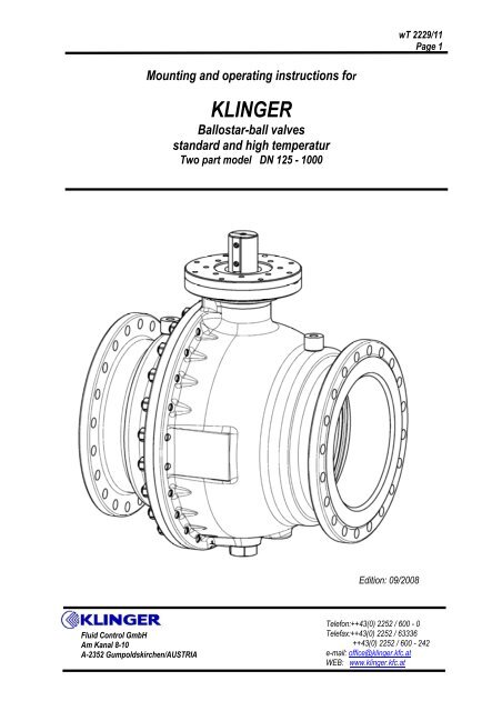
Mounting and operating instructions for<br />
KLINGER<br />
Ballostar-ball valves<br />
standard and high temperatur<br />
Two part model DN 125 - 1000<br />
Edition: 09/2008<br />
Fluid Control GmbH<br />
Am Kanal 8-10<br />
A-2352 Gumpoldskirchen/AUSTRIA<br />
Telefon:++43(0) 2252 / 600 - 0<br />
Telefax:++43(0) 2252 / 63336<br />
++43(0) 2252 / 600 - 242<br />
e-mail: office@klinger.kfc.at<br />
WEB: www.klinger.kfc.at
wT 2229/11<br />
Page 2<br />
TABLE OF CONTENTS<br />
Page 3 Functional principle<br />
Page 4 – 6 Mode of operation<br />
Page 7 – 8 Operation instructions<br />
Page 9 – 10 Installation instructions<br />
Page 11 Commissioning and Safety Instructions<br />
Page 12 Dis<strong>assembly</strong> drawing<br />
Page 13 – 19 Spare parts <strong>assembly</strong><br />
Page 20 Installation instructions for actuator <strong>assembly</strong><br />
Page 21 Material code numbers<br />
Page 22 Component parts designation and material<br />
Page 23 – 35 Spare parts
wT 2229/11<br />
Page 3<br />
DN 125-200<br />
DN 250-1000<br />
1 Body<br />
2 Single-ended flanged nipple<br />
3 Operating stem<br />
4 Ball<br />
5 Bearing journal<br />
7 Flange<br />
8 Bush insert, upper part<br />
10 Bush insert lower part<br />
12 Disk<br />
13 Gasket<br />
14 Gasket<br />
15 Cushion joint<br />
16 Cushion joint<br />
17 O-ring<br />
18 O-ring (spiral wound gasket at WI)<br />
19 O-ring<br />
20 O-ring<br />
21 U-sleeve<br />
22 Sealing element<br />
23 Wire ring<br />
24 Back-up ring<br />
25 O-ring<br />
26 Rating plate<br />
27 Fillister head screw<br />
28 Grooved drive stud<br />
29 Circlip<br />
30 O-ring<br />
31 Fillister head screw<br />
32 Hexagon nut<br />
33 Stud<br />
34 Fillister head screw<br />
35 Hexagon head screw<br />
36 Feather key<br />
37 Feather key<br />
38 Bearing bush<br />
39 Bearing bush<br />
40 Bearing bush<br />
41 Locking screw<br />
42 Gasket
wT 2229/11<br />
Page 4<br />
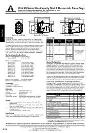
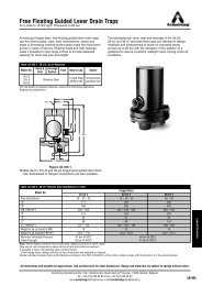
Functional principle<br />
The ball valve guarantees tightness under exposure both high and low pressures through its “ELASTIC<br />
SEALING SYSTEM”. This tightness is achieved with two elastic sealing elements which work<br />
independently of one another. The required application forces are generated first by applying an initial<br />
stress during the <strong>assembly</strong>, and second by the differential pressure arising in the valve fitting (Figure 1).<br />
Comprised of the shut-off cross section multiplied by the pending differential pressure, the forces<br />
coming about on the shut-off ball valve are not conveyed to the sealing rings, but directly to the ball<br />
bearings which were installed for this very purpose. As a result, the bearing and sealing functions are<br />
separated by design. This keeps the torque required for swivelling the shut–off fitting low. The closing<br />
behaviour of these ball valves with balls running on bearings gives them a long service life.<br />
Figure 1
wT 2229/11<br />
Page 5<br />
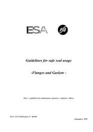
MODE OF OPERATION<br />
During the <strong>assembly</strong> of the body and connection piece, the sealing system is elastically at the ball. The<br />
two prestressed elastic sealing elements made of stainless steel in conjunction with the sealing rings<br />
and a seal at the periphery of the outer diaphragm form a system with the ball on the ball on the inlet<br />
and outlet side of the ball valve. A back-up ring protects the elastic sealing elements against excess<br />
stress, while a wire ring acts to hold the sealing unit in place (Figure 2).<br />
Figure 2<br />
U-sleeve, O-ring<br />
Wire ring<br />
Back-up ring<br />
Sealing ring<br />
Ball<br />
As a result of the elasticity, two primary sealing points are always present of the valve opening up to a<br />
certain pressure. The differential surface areas on the sealing elements cause the pressure of the<br />
medium to press the sealing ring against the ball surface on the inlet side of the ball valve. The sealing<br />
element arranged on the side not exposed to the pressure or outlet side is lifted by the ball surface<br />
when the clearance space between the sealing ring is exposed to a pressure exceeding the nominal<br />
pressure.<br />
Figure 3<br />
Medium pressure<br />
Clearance space relief at<br />
exceeding of the nominal pressure<br />
Depressurised<br />
The ball valve may be pressurised in both directions of flow. Heat expansions are compensated by the<br />
elasticity of the sealing elements.
wT 2229/11<br />
Page 6<br />
The special sealing system allows you to evacuate, vent or pressure-relieve the ball valve clearance<br />
space by the way of a discharge connection with the valve fitting closed. This makes it possible to check<br />
the function of the two sealing rings after relieving the pressure (Block & Bleed).<br />
Figure 4<br />
Medium pressure<br />
Medium pressure<br />
Discharge fitting<br />
Repairs on a relieved section of line between two ball valves may also be safely done on the side of the<br />
line exposed to pressure without the medium penetrating into the section under repair.<br />
The operating stem is used to switch the ball. The shaft-hub connection is established with the feather<br />
keys. The seal to the outside is brought about with O-rings arranged in series. These O-rings are placed<br />
in a bush insert for easier replace ability. The arising forces are absorbed by two dry lubrication<br />
bearings.<br />
Figure 5<br />
Bush insert, Upper part<br />
Static O-ring<br />
O-rings<br />
Bush insert. Lower part<br />
Dry lubrication bearings<br />
Feather keys<br />
Operating stem<br />
Ball hub
wT 2229/11<br />
Page 7<br />
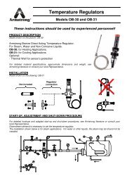
In order to ensure a concentric position of the balls, the opposite side has a bearing journal attached to<br />
it,, which is routed into the vertical boring of the ball by way of a dry lubrication bearing, and fixed into<br />
position against arising forces in the body with a hexagon head screw. The seal to the outside is<br />
established with gaskets or an O-ring.<br />
The division between the body and the connection piece is sealed by means of a static O-ring. The<br />
parts are held together with a screwed connection, i.e. the metallic flanges are pressed on one another<br />
over the entire surface area. This surface area absorbs the arising tensile and bending forces.<br />
Ball<br />
Static O-ring<br />
Stud<br />
Figure 6a<br />
Cushion joints<br />
Circlip<br />
Dry lubrication bearing<br />
Hexagon nut<br />
Connection piece<br />
Body<br />
Figure 6b<br />
Bearing journal<br />
O-ring for DN 700, 800,<br />
PN25/40<br />
Metallic flange gasket<br />
spiral wound gasket<br />
All seals and bearings are MAINTENANCE FREE.
wT 2229/11<br />
Page 8<br />
OPERATING INSTRUCTIONS<br />
Ballostar ball valves are delivered in the OPEN setting. The connections are covered to safeguard<br />
against contamination and damage. We recommend that these plugs only be removed shortly before<br />
installing the valve fitting.<br />
The ball valves are to be stored in closed areas with non-aggressive atmosphere and protected against<br />
moisture and contamination. In addition, one must make sure not to use the valve fitting for higher<br />
temperatures and pressures than intended. Only under these conditions can a warranty be extended for<br />
the indicated time.<br />
Parts subjected to corrosion, erosion, etc. during operations or to natural wear are excluded.<br />
Ball valves are MAINTENANCE FREE!<br />
During prolonged standstills, the valve fitting must be emptied for freezing media, while pressure relief<br />
must be provided for expanding media.<br />
In the event of leaks to the outside, the torques of the screws have to be checked at the appropriate<br />
locations according Tables 1,2 and 3.<br />
To increase the live time in service with lo quantity of operations, <strong>Klinger</strong> suggest<br />
to operating the ball valve from time to time.<br />
It is sufficiently to move the ball only some degree of an angle (to break free)<br />
Table 1 Torques of the dividing flange bolts (item33)<br />
Nominal<br />
Torques<br />
Width of ball<br />
Dimension<br />
VII, VIII, X Xc<br />
125,150 M 16 160 94<br />
200 M 20 310 142<br />
250 M 22 320 142<br />
300 M 24 470 228<br />
350 M 22 320 189<br />
400 M 27 650 255<br />
500 M 30 1000<br />
600 M 33 1400<br />
700 M 36 1900<br />
800 M 39 2200<br />
1000 M39 1800<br />
see page 22<br />
for explanation to material<br />
code numbers
wT 2229/11<br />
Page 9<br />
Table 2 Torque of bearing journal screw (item 35)<br />
Norminal<br />
Torques (Nm)<br />
Dimension<br />
width of ball<br />
VII, VIII, X Xc<br />
125,150 M 24 270 270<br />
200 M 30x2 540 540<br />
250,300 M 36x1,5 900 900<br />
350,400 M 48x1,5 2100 2100<br />
500,600 M 60x2 5300<br />
700,800 M 85x2 19800<br />
1000 M 95x2 21000<br />
Table 3 Torque of mounting flange bolt (item 31)<br />
Norminal<br />
Torques (Nm)<br />
Dimension<br />
width of ball<br />
VII, VIII, X Xc<br />
125,150 M 12 28 39<br />
200 M 16 68 94<br />
250,300 M 16 220 94<br />
350,400 M 20 428 142<br />
500,600 M 20 428<br />
700,800 M 30 1478<br />
1000 M 36 950<br />
Table 4 Torque of locking screw (item 41)<br />
Norminal<br />
Torques (Nm)<br />
Dimension<br />
width of ball<br />
VII, VIII, X Xc<br />
150 M 8 x 12 27 12<br />
200 M 8 x 20 27 12<br />
250 M 10 x 20 52 24<br />
300 M 10 x 25 52 24<br />
350,400 M 12 x 45 91 39<br />
500 M 16 x 45 220<br />
600 M 16 x 55 220<br />
700,800 M 20 x 40 428<br />
1000 M 20 x 40 428
wT 2229/11<br />
Page 10<br />
INSTALLATION INSTRUCTIONS<br />
The ball valves are delivered in the OPEN setting with a sealed valve opening.<br />
INSTALLATION:<br />
Ballostar ball valves may be installed in any desired position. They should be in OPEN setting during the<br />
installation to prevent damage to the ball surface. The cover discs are only to be removed just prior to<br />
installation.<br />
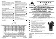
• Pulleys appropriate for the weight and the eyebolts located on the ball are used for manipulation<br />
purposes. See <strong>Klinger</strong> catalogue for standard ball valve weights.<br />
Figure 7<br />
Standard with DN 400<br />
Eyebolts<br />
Eyebolts can be provided for all nominal widths at the request of the customer.
wT 2229/11<br />
Page 11<br />
• Follow the attached welding instructions during installations for ball valves with welded ends.<br />
Because of the overall length selected for this type of ball valve the device need not to be dismantled<br />
If it is welded in a workman-like manner, but instead it should may be welded into the pipeline as a<br />
complete valve fitting.<br />
The temperature while preheating and welding should not exceed 200°C at a distance of 115 mm from<br />
the weld up to DN350, and at a distance of 170 mm starting at DN 400.<br />
Take care of welding quality-requirements according to the welding manual.<br />
We can only guarantee the tightness of our ball valves if they are welled skilfully.<br />
Figure 8<br />
Support<br />
Slide plate
wT 2229/11<br />
Page 12<br />
COMMISSIONING<br />
• After installation and before commissioning, make sure that solid, not constituting part of the<br />
medium are removed from the pipeline.<br />
• Functional test<br />
• Pressure test<br />
We remind you that damage caused by parts strange to the medium are not covered under our<br />
warranty.<br />
Safety Instructions<br />
In general the using of these valves is without any risks. For this it is necessary to act with enough care.<br />
● For the respective application of the valves please take care of the Safety Directions for<br />
pressure/temperature limits and the selection of materials in the relevant product catalogue.<br />
● Be careful in case of the use of cast iron for pressure wetted parts. This material is a rigid material<br />
and very sensitive against rapidly pressure changings and tensile peaks. At the building of the<br />
network care has to be taken, to avoid pressure impacts (water hammers).<br />
• The mounting and installation can be done ONLY when the pipe is completely empty and<br />
pressure released.<br />
• Do not untighten any screws on pressure tightening parts, unless advised and described in the<br />
Assembly Instructions and Handling Regulations.<br />
• The Assembling as well as handling should be done only by qualified people.<br />
• Please do make sure that all connecting pieces are well tightened again, if you had to untighten<br />
them before.<br />
• Do not open any screws with violence.<br />
• ATTENTION – when opening and closing drain cocks – DANGER caused by leakage of Medium.<br />
If the valve is used in superheated water, the drain cock may only opened if an<br />
appropriate backpressure is in the drainpipe or the temperature of the medium is<br />
lower than 100°C (prevention of steam hammer in the dead camber<br />
• ATTENTION – take care with movable parts : specially with electric/pneumatic actuators<br />
YOU MIGHT HIRT YOURSELF!!!<br />
This Assembly Instructions and Handling Regulations has to be passed over to the people working with<br />
this valves.<br />
ATTENTION: as per dismantling the actuator and before the connecting screws are to be<br />
unscrewed, the actuator has to be secured in his mounting position against distortion
wT 2229/11<br />
Page 13
wT 2229/11<br />
Page 14<br />
SPARE PARTS ASSEMBLY<br />
SEAL REPLACEMENT on the operating stem with the valve fitting installed.<br />
Bush inserts – upper part (item 8)<br />
• Depressurise the line<br />
• Switch valve fitting to OPEN setting<br />
• Dismantle cock handle or drive unit<br />
• Loosen mounting flange bolts (item 31) and take off flange (item 7) with sealing ring (item 17) over<br />
the shaft end.<br />
• Remove cushion joints (item 16). The same number of identical cushion joints must be installed<br />
again during <strong>assembly</strong>.<br />
• Pull bush inserts, upper part (item 8) out of body using extraction groove.<br />
• Replace seals (items 20,17) according to spare parts list. Clean components thoroughly and<br />
lubricate with the corresponding grease to facilitate installation<br />
• Check the bearing surface (item 38). Replace the bearing if damage is present<br />
• Rebuild in reverse order<br />
Figure 9<br />
31<br />
7<br />
locking screw Pos.41<br />
″EXPULSION FUSE″<br />
16<br />
38<br />
8<br />
17<br />
Groove for extraction from body<br />
20
wT 2229/11<br />
Page 15<br />
The seal may be placed on the bush insert, upper part under operating conditions for the version having<br />
a bush insert, lower part safeguarded against expulsion given the use of harmless media.<br />
If the valve fitting has been dismantled from the line, we also recommend that the spare parts on the<br />
bush insert lower part be replaced (item 12)<br />
Prior bush insert variants for WKZ VIII, X, Xc up until 1992.<br />
These should be replaced with the new version corresponding to the material code number in the event<br />
of dis<strong>assembly</strong> and damage.<br />
DISASSEMBLY OF COMPONENTS<br />
When replacing the sealing elements the following steps have to be taken:<br />
• Switch ball valve to OPEN setting<br />
• Depressurise line<br />
• Dismantle valve fitting from pipeline. Place on the body connection side for easier handling while<br />
dismantling the components. Use a support which doesn’t damage the bearing surface.<br />
• Identify the areas where the parts were removed in relation to each other (I) (Figure 10) Loosen<br />
hexagon nuts (item 32), lift single-ended flanged nipple (item 2) and place on the<br />
connection side<br />
32<br />
Figure 10<br />
19<br />
Identification mark<br />
Identification mark<br />
2
wT 2229/11<br />
Page 16<br />
• Take off sealing ring (item 19)<br />
• Screw hexagon head screws (item 35) out of bearing journal (item 5) remove gasket (item 14)<br />
• Dismantle circlip (item 29) from ball hub, remove discs (item 12) to centre for height<br />
ATTENTION: The same number of identically strong cushion joints must be used again during<br />
<strong>assembly</strong>.<br />
Figure 11<br />
14<br />
13<br />
5<br />
12<br />
29<br />
35<br />
Bearing (item 39)<br />
If the inner surface of the<br />
bearing is unhurt, the bearing<br />
stays in the ball<br />
• Insert bearing journals (item 5) into the ball valve opening (knock out carefully), remove gasket<br />
(item 13)<br />
• Dismantle <strong>assembly</strong> parts on the operating stem end, such as the cock handle, mechanical gearing,<br />
extensions, consoles, etc<br />
• Unscrew mounting flange bolts (item 31) and take off flange (item 7) with sealing ring<br />
(item 17) over the shaft end. Remove cushion joints (item 16). If there is a locking screw (item 41)<br />
and seal which hold the bush insert lower part is present, the costumer has to remove them first<br />
(item 42)<br />
41<br />
Figure 12<br />
42<br />
10 8 3 17 7 31<br />
15 20<br />
16
wT 2229/11<br />
Page 17<br />
• Knock the operating stem (item 3) and bush inserts (items 8,10) carefully out of the body along with<br />
sealing rings and bearing bushes<br />
• Turn the ball manually by 90°, lift it out of the body and place it on a suitable support<br />
Figure 13<br />
Assembly of sealing element using body and connection piece<br />
• Screw fillister head screws (item 27) along with serrated lock washer (item 43) if present (starting in<br />
the year 1991) out of the back-up ring (item 24).<br />
• The open ends of the wire ring have to be pressed together (item 23) and lifted out of the groove<br />
• Insert two larger opposing screw drivers into the gap between the sealing element and body<br />
(connection piece), use it as a lever to press sealing element (item 22) and back-up ring (item 24)<br />
out of the turned groove. Take the remaining seals (items 18, 21) out of interior.<br />
Figure 14<br />
27<br />
43 23<br />
24 22<br />
18, 21<br />
ATTENTION:<br />
All components particularly the seals and the sealing surfaces, are to be<br />
conscientiously checked before <strong>assembly</strong>, and replaced by new parts in the event of<br />
damage. Visible contamination on the machined locations must be cleaned. Cleaned<br />
components are to be provided with a uniformly thin layer of grease prior to installation.
wT 2229/11<br />
Page 18<br />
STANDARD lubrication chart:<br />
O-rings: Silicon grease OKS 01110, MOLYKOTE 55 M<br />
other parts: Mobilplex 47<br />
In special cases the lubricant prescribed while ordering must be used.<br />
For example: SYNTHESOL UG1 for hydrocarbons AIRPRESS C 40 kp for oxygen systems.<br />
ASSEMBLY<br />
• The modular system makes it possible to fit the sealing elements with special sealing rings as<br />
requirements dictate. All sealing elements are reassembled and ready to install!<br />
Sealing elements are according to needs.<br />
Metallic sealing elements for special requirements:<br />
Applications in which the load carrying capacity of soft-sealing<br />
rings is overtaxed, e.g. for media having solid content, etc.<br />
• Insert new sealing elements (item 22)<br />
• Slip over sealing ring (item 18) on the periphery of the sealing elements and press down, put on U-<br />
sleeve (item 21) with closed facing up, gently pinch the open side and press into the groove.<br />
• Insert back-up ring (item 24) and secure it with a wire ring (open wire ring end in the area of the<br />
bearing journal). The latter must lock into place in the snap ring groove by widening the open end to<br />
ensure a tight fit. Should it be difficult to bring the wire ring into its position, the sealing element has<br />
to be spring-mounted. Press down the back-up ring using two space blocks and a U-iron fragment,<br />
which is clamped down by two hexagon nuts.<br />
24<br />
21<br />
18<br />
22<br />
27<br />
43<br />
24<br />
U-iron<br />
Figure 15<br />
Spacer blocks<br />
• Screw fillister head screws (item 27) with serrated lock washers (item 43) into the threaded holes of<br />
the back-up ring until tight<br />
• Remove back-up ring <strong>assembly</strong> aid<br />
• Lift ball in body (hub with feather key grooves on operating stem end) and place on sealing element
wT 2229/11<br />
Page 19<br />
• Turn ball manually to OPEN setting<br />
• Preassemble bush inserts (item 8,10) with all components (item 15,20,38) on operating stems,<br />
place feather keys (item 36) in existing groves and screw down (item 34)<br />
• Insert operating stem with components on the mounting flange end into body, and introduce ball unit<br />
collar sets on ball hub. Install seal (item 17) and cushion joints (item 16).<br />
• Place on flange (item 7) in correct position and gasket down on body separated by block (item 31)<br />
• Screw in locking screws (item 41) and seal (item 42) if present, and secure bush inserts, lower part.<br />
• Place new degreased soft nickel gasket (item 13) into body groove, insert bearing journal (item 5)<br />
through ball hub, and screw hexagon screw (item 35) with new metallic gasket (item 14) into the<br />
bearing journal thread.<br />
• The prestress of the sealing element might make it necessary to press down the ball, so that the<br />
bearing journal can be introduced into the body insertion point. Clamp down with mounting device in<br />
such a way that the location holes are aligned.<br />
Clamping device<br />
Protection joint<br />
Figure 16<br />
41<br />
35 14 13 5 12 29<br />
42<br />
10<br />
8<br />
3 34 17<br />
7<br />
31<br />
36<br />
15<br />
38 38 37<br />
16<br />
DN700,800<br />
20<br />
30<br />
• Tighten bearing journal screw (item 35) with the prescribed torque (Table 2) (if necessary, counterlock<br />
on the inside with two-hole keys).<br />
• Take the same number of identically strong cushion joints (item 12) present during dis<strong>assembly</strong> and<br />
place them on bearing journal. Fix the cushion joints into position using circlip (item 29), which must<br />
engage in the provided groove at the ball hub.<br />
No circlip is on hand for nominal balls widths DN 125, 150. The ball is concentrically adjusted in the<br />
sealing elements.<br />
• Functional test<br />
• Place connection piece (item 2) along with sealing ring (item 19) on the body in the marked position<br />
and let them lock into place in the centring shoulder<br />
• Screw nuts (item 32) on projecting studs and tighten cross-wise with the indicated torque (Table 1)<br />
• Assemble the parts for installation (cock handle, mechanical gearing, etc.)<br />
ATTENTION: Turn ball valve TO RIGHT to close.
wT 2229/11<br />
Page 20<br />
ATTENTION:<br />
If the ball is not properly aligned in its axial position or if the axial play is too high,<br />
(DN 200 – 400 max. 0,3 mm; DN 500 – 1000 max. 0,5 mm) then the cushion joints<br />
must be used to position them in the centre of the body.<br />
Alignment between the ball valve opening and sealing element takes place in the OPEN setting, either<br />
visually or using a measuring instrument.<br />
Figure 17<br />
a) Cushion joints (item 12) on the bearing journal<br />
• The space measured between the bearing journal and the lower edge of the circlip determines the<br />
height of the cushion joints.<br />
• Set the cushion joints<br />
• Set protection ring (item 29)<br />
• Push the ball in direction of the journal pin to the present position.<br />
12<br />
29<br />
Figure 18<br />
b) Cushion joints (item 16) at head-flange<br />
• The projecting length from the bush insert over the body should be compared with the measured<br />
dept of recess for the bush insert on the flange.<br />
• Measure difference minus 0,3 or 0,5 (required axial play) gives the height of the charging cushion<br />
joints.<br />
• Mounting of flange (item 7)<br />
16<br />
Figure 19<br />
7
wT 2229/11<br />
Page 21<br />
INSTALLATION INSTRUCTIONS FOR ACTUATOR ASSEMBLY<br />
Preparation:<br />
The actuator must be designed with a torque corresponding to the nominal width. The valves are to be<br />
set following a technical consultation (pressure, sealing material, media, etc.) with the manufacturer.<br />
The connecting parts must be fabricated in accordance with the size of the actuator.<br />
Coupling<br />
Figure 20<br />
Coupling<br />
Intermediate flange<br />
Console<br />
Square DN 125 – 200<br />
Feather key DN 250 – 1000<br />
Actuator <strong>assembly</strong> work may also be done subsequently at any time without dismantling the valve<br />
fitting.<br />
Standard mounting flange according to ISO 5211.<br />
ASSEMBLY<br />
• Switch ball valve to OPEN setting<br />
• Place on coupling piece<br />
• Fasten on console or connecting flange to ball valve<br />
• Place on actuator in correct position and screw down. Pin together, if necessary.<br />
ATTENTION: Turn valve fitting to right to close.<br />
Make sure that the 90° movement between its end settings ON and OFF is precisely<br />
maintained.<br />
• Functional test
wT 2229/11<br />
Page 22<br />
Material codes for <strong>Klinger</strong> Ballostar – Ball valves<br />
Symbol Body/connection piece Internal parts Colour of cock<br />
III Grey cast iron No non-ferrous metal parts Grey RAL 7005<br />
VII Cast steel Non-ferrous metal parts possible Grey RAL 5015<br />
VIII Cast steel No non-ferrous metal parts Grey RAL 5015<br />
X Acid-proofed cast steel Acid-proofed steel parts which have Bright<br />
contact with the medium<br />
Xc Acid-proofed cast steel All acid-proofed stainless steel parts Bright<br />
Major item of the material code is the basic material of body and connecting piece<br />
used materials:<br />
DIN material<br />
number<br />
DIN token<br />
EN material<br />
code.<br />
EN token<br />
Grey steel iron 0.6025 GG-25 EN-JL1040 EN-GJL-250<br />
Cast steel 1.0619 GS-C25 1.0619 GP240GH<br />
Acid-proofed cast steel 1.4408 GX6CrNiMo18-10 1.4408 GX5CrNiMo19-11-2<br />
Face to face dimensions, area of application etc. are configured in the catalogue
PARTS LIST<br />
*) O-Ring compound in accordance to the service conditions<br />
Standard grade: Aflas (AF) FEPM<br />
Steam and hot water design (WI) Fluoraz 799G<br />
**) Gasket in accordance to the service conditions<br />
Standard grade: Aflas (AF) FEPM<br />
Steam and hot water design (WI) Spiral wounded gasket (Graphit/1.4541)<br />
wT 2229/11<br />
Page 23<br />
Item Spare parts<br />
Components<br />
Wkz VII Wkz VIII X Xc<br />
Materials<br />
1 Body 1.0619.01 1.0619.01 1.4408 1.4408<br />
2 Connection piece 1.0619.01 1.0619.01 1.4408 1.4408<br />
3 Operating stem 1.4104 1.4104 1.4401 1.4401<br />
4 Ball 0.7043FeCr30 0.7043 FeCr30 1.4408 1.4408<br />
5 Bearing journal 1.4101 1.4104 1.4401 1.4401<br />
7 Flange 1.0116 1.0116 1.4401 1.4401<br />
8 Bush insert – UP 1.0580phrf 1.0580phrf 1.4401w.n. 1.4401w.n.<br />
10 Bush insert – LP 1.0580phrf 1.0580phrf 1.4401w.n. 1.4401w.n.<br />
12 Disk 1.4101 1.4101 1.4401 1.4401<br />
13 Gasket Soft nickel *<br />
14 Gasket Soft nickel *<br />
15 Cushion joint KFC-25 *<br />
16 Cushion joint K-Sil *<br />
17 O-ring *) *<br />
18 O-ring *) *<br />
19 O-ring **) *<br />
20 O-ring *) *<br />
21 U-sleeve KFC-25 *<br />
22 Sealing element VII-KFC VII-KFC X-KFC X-KFC *<br />
23 Wire ring 1.4401.07<br />
24 Back-up ring 0.6020phrf 0.6020phrf 1.4408 1.4408<br />
25 O-ring *) *<br />
26 Rating plate 1.4305<br />
27 Fillister head screw A 4<br />
28 Grooved drive stud A 2<br />
29 Circlip 1.4310<br />
30 O-ring *) *<br />
31 Fillister head screw 10.9 10.9 10.9 A 4<br />
32 Hexagon nut 8 8 8 E2P A 4-70<br />
33 Stud 8.8 8.8 8.8 E2P A 4-70<br />
34 Fillister head screw A 4 A 4 A 4 A 4<br />
35 Hexagon head screw 1.1181 1.1181 1.1181 1.4305<br />
36 Feather key 1.0052.07 1.0052.07 1.4401 1.4401<br />
37 Feather key 1.0052.07 1.0052.07 1.0052.07 1.4401<br />
38 Bearing bush St/Bz/Flon AISI 316L/PTFE 90 *<br />
39 Bearing bush St/Bz/Flon AISI 316L/PTFE 90 *<br />
40 Bearing bush St/Bz/Flon AISI 316L/PTFE 90 *<br />
41 Locking screw 10.8 A4<br />
42 Gasket copper
wT 2229/11<br />
Page 24<br />
SPARE PARTS LIST<br />
Ballostar - ball valve DN 150/125 PN25/40<br />
Item<br />
Pce<br />
Name<br />
Materials by Wkz<br />
s components VII VIII X Xc<br />
Dimension<br />
13 1 Gasket Soft nickel 35/43x1 KLN 1<br />
14 1 Gasket Soft nickel 26/36x1 KLN 1<br />
15 1 Cushion joints KFC-25 45/54x1 KLN 2435/1<br />
16 3 Cushion joints K-Sil 46/58x0,5 46/58x0,3<br />
17 1 O-ring *) ARP 228 (56,74x3,53)<br />
18 2 O-ring *) ARP 260 (164,69x3,53)<br />
19 1 O-ring/spiral wound gasket **) ARP266 (202,79x3,53)/Ø222,5x206x4,5<br />
20 1 O-ring *) ARP 328 (46,99x5,33)<br />
21 2 U-sleeve KFC-25 125 KLN 2416<br />
22 2 Sealing element VIII/KFC X-KFC 125 KLN 2414/2 ***)<br />
25 2 O-ring *) equal to pos.20<br />
38 2 Bearing bush<br />
St/Bz/Flon MB 4520 DU KLN 2438/1<br />
AISI 316 L/PTFE 90 PI 4519 KLN 2438/2<br />
39 1 Bearing bush<br />
St/Bz/Flon MB 5030 DU KLN 2438/1<br />
AISI 316 L/PTFE 90 PI 5029 KLN 2438/2<br />
*) O-Ring compound in accordance to the service conditions<br />
Standard grade: Aflas (AF) FEPM<br />
Steam and hot water design (WI) Fluoraz 799G<br />
**) Gasket in accordance to the service conditions<br />
Standard grade: Aflas (AF) FEPM<br />
Steam and hot water design (WI) Spiral wounded gasket (Graphit/1.4541)<br />
***) sealing elements<br />
in accordance to specification by special design<br />
equipped with metal sealing ring<br />
In the interest of technical progress, designs and dimensions are subject of modification
wT 2229/11<br />
Page 25<br />
SPARE PARTS LIST<br />
Ballostar - ball valve DN 150 PN25/40<br />
DN 200/150 PN25<br />
DN 200/150 PN16<br />
Item Pces<br />
Name<br />
Materials by Wkz<br />
components VII VIII X Xc<br />
Dimension<br />
13 1 Gasket Soft nickel 35/43x1 KLN 1<br />
14 1 Gasket Soft nickel 26/36x1 KLN 1<br />
15 1 Cushion joints KFC-25 45/54x1 KLN 2435/1<br />
16 3 Cushion joints K-Sil 46/58x0,5 46/58x0,3<br />
17 1 O-ring *) ARP 228 (56,74x3,53)<br />
18 2 O-ring *) ARP 265 (196,44x3,53)<br />
19 1 O-ring/spiral wound gasket **) ARP 271 (234,54x3,53)/Ø259x242x4,5<br />
20 1 O-ring *) ARP 328 (46,99x5,33)<br />
21 2 U-sleeve KFC-25 150 KLN 2416<br />
22 2 Sealing element VIII/KFC X-KFC 150 KLN2414/2 ***)<br />
25 2 O-ring *) equal to pos.20<br />
38 2 Bearing bush<br />
St/Bz/Flon MB 4520 DU KLN 2438/1<br />
AISI 316 L/PTFE 90 PI 4519 KLN 2438/2<br />
39 1 Bearing bush<br />
St/Bz/Flon MB 5030 DU KLN 2438/1<br />
AISI 316 L/PTFE 90 PI 5029 KLN 2438/2<br />
*) O-Ring compound in accordance to the service conditions<br />
Standard grade: Aflas (AF) FEPM<br />
Steam and hot water design (WI) Fluoraz 799G<br />
**) Gasket in accordance to the service conditions<br />
Standard grade: Aflas (AF) FEPM<br />
Steam and hot water design (WI) Spiral wounded gasket (Graphit/1.4541)<br />
***) sealing elements<br />
in accordance to specification by special design<br />
equipped with metal sealing ring<br />
In the interest of technical progress, designs and dimensions are subject of modification
wT 2229/11<br />
Page 26<br />
SPARE PARTS LIST<br />
Ballostar - ball valve DN 200 PN25/40<br />
DN 250/200 PN25/40<br />
Item Pces<br />
Name<br />
Materials by Wkz<br />
components VII VIII X Xc<br />
Dimension<br />
13 1 Gasket Soft nickel 36/55x1 KLN 1<br />
14 1 Gasket Soft nickel 35/43x1 KLN 1<br />
15 1 Cushion joints KFC-25 60/70x1 KLN 2435/1<br />
16 3 Cushion joints K-Sil 61/75x0,5 61/75x0,3<br />
17 1 O-ring *) ARP 233 (72,62x3,53)<br />
18 2 O-ring *) ARP 274 (253,59x3,53)<br />
19 1 O-ring/spiral wound gasket **) ARP278 (304,39x3,53)/Ø344,5x328x4,5<br />
20 1 O-ring *) ARP 332 (59,69x5,33)<br />
21 2 U-sleeve KFC-25 200 KLN 2416<br />
22 2 Sealing element VIII/KFC X-KFC 200 KLN 2414/2***)<br />
25 2 O-ring *) equal to pos.20<br />
38 2 Bearing bush<br />
St/Bz/Flon MB 6028 DU KLN 2438/1<br />
AISI 316 L/PTFE 90 PI 6029 KLN 2438/2<br />
39 1 Bearing bush<br />
St/Bz/Flon MB 6044 DU KLN 2438/1<br />
AISI 316 L/PTFE 90 PI 6044 KLN 2438/2<br />
*) O-Ring compound in accordance to the service conditions<br />
Standard grade: Aflas (AF) FEPM<br />
Steam and hot water design (WI) Fluoraz 799G<br />
**) Gasket in accordance to the service conditions<br />
Standard grade: Aflas (AF) FEPM<br />
Steam and hot water design (WI) Spiral wounded gasket (Graphit/1.4541)<br />
***) sealing elements<br />
in accordance to specification by special design<br />
equipped with metal sealing ring<br />
In the interest of technical progress, designs and dimensions are subject of modification
wT 2229/11<br />
Page 27<br />
SPARE PARTS LIST<br />
Ballostar - ball valve DN 250 PN25/40<br />
DN 300/250 PN40<br />
Item Pces<br />
Name<br />
Materials by Wkz<br />
components VII VIII X Xc<br />
Dimension<br />
13 1 Gasket Soft nickel 50/65x1 KLN 1<br />
14 1 Gasket Soft nickel 36/55x1 KLN 1<br />
15 1 Cushion joints KFC-25 70/80x1 KLN 2435/1<br />
16 3 Cushion joints K-Sil 71/85x0,5 71/85x0,3<br />
17 1 O-ring *) ARP 236 (82,14x3,53)<br />
18 2 O-ring *) ARP 278 (304,39x5,33)<br />
19 1 O-ring/spiral wound gasket **) ARP 281 (380,59x3,53)/Ø414,5x398x4,5<br />
20 1 O-ring *) ARP 335 (69,22x5,33)<br />
21 2 U-sleeve KFC-25 250 KLN 2416<br />
22 2 Sealing element VIII/KFC X-KFC 250 KLN 2414/2 ***)<br />
25 *) equal to pos.20<br />
38 2 Bearing bush<br />
St/Bz/Flon MB 7040 DU KLN 2438/1<br />
AISI 316 L/PTFE 90 PI 7040 KLN 2438/2<br />
39 1 Bearing bush<br />
St/Bz/Flon MB 7050 DU KLN 2438/1<br />
AISI 316 L/PTFE 90 PI 7050 KLN 2438/2<br />
*) O-Ring compound in accordance to the service conditions<br />
Standard grade: Aflas (AF) FEPM<br />
Steam and hot water design (WI) Fluoraz 799G<br />
**) Gasket in accordance to the service conditions<br />
Standard grade: Aflas (AF) FEPM<br />
Steam and hot water design (WI) Spiral wounded gasket (Graphit/1.4541)<br />
***) sealing elements<br />
in accordance to specification by special design<br />
equipped with metal sealing ring<br />
In the interest of technical progress, designs and dimensions are subject of modification
wT 2229/11<br />
Page 28<br />
SPARE PARTS LIST<br />
Ballostar - ball valve DN 300 PN25/40<br />
DN 350/300 PN40<br />
Item Pces<br />
Name<br />
Materials by Wkz<br />
components VII VIII X Xc<br />
Dimension<br />
13 1 Gasket Soft nickel 50/65x1 KLN 1<br />
14 1 Gasket Soft nickel 36/55x1 KLN 1<br />
15 1 Cushion joints KFC-25 70/80x1 KLN 2435/1<br />
16 3 Cushion joints K-Sil 71/85x0,5, 71/85x0,3<br />
17 1 O-ring *) ARP 236 (82,14x3,53)<br />
18 2 O-ring *) ARP 383 (354,97x5,33)<br />
19 1 O-ring/spiral wound gasket **) ARP 284 (456,06x5,33)/Ø486,5x470x4,5<br />
20 1 O-ring *) ARP 335 (69,22x5,33)<br />
21 2 U-sleeve KFC-25 300 KLN 2416<br />
22 2 Sealing element VIII/KFC X-KFC 300 KLN 2414/2 ***)<br />
25 2 O-ring *) equal to pos.20<br />
38 2 Bearing bush<br />
St/Bz/Flon MB 7040 DU KLN 2438/1<br />
AISI 316 L/PTFE 90 PI 7040 KLN 2438/2<br />
39 1 Bearing bush<br />
St/Bz/Flon MB 7050 DU KLN 2438/1<br />
AISI 316 L/PTFE 90 PI 7050 KLN 2438/2<br />
*) O-Ring compound in accordance to the service conditions<br />
Standard grade: Aflas (AF) FEPM<br />
Steam and hot water design (WI) Fluoraz 799G<br />
**) Gasket in accordance to the service conditions<br />
Standard grade: Aflas (AF) FEPM<br />
Steam and hot water design (WI) Spiral wounded gasket (Graphit/1.4541)<br />
***) sealing elements<br />
in accordance to specification by special design<br />
equipped with metal sealing ring<br />
In the interest of technical progress, designs and dimensions are subject of modification
wT 2229/11<br />
Page 29<br />
SPARE PARTS LIST<br />
Ballostar - ball valve DN 350 PN25/40<br />
DN 400/350 PN40<br />
Item Pces<br />
Name<br />
Materials by Wkz<br />
components VII VIII X Xc<br />
Dimension<br />
13 1 Gasket Soft nickel 60/85x1 KLN 1<br />
14 1 Gasket Soft nickel 50/75x1 KLN 1<br />
15 1 Cushion joints KFC-25 90/105x1 KLN 2435/1<br />
16 5 Cushion joints K-Sil 91/110x0,5 91/110x0,3<br />
17 1 O-ring *) ARP 245 (110,72x3,53)<br />
18 2 O-ring *) ARP 386 (430,66x5,33)<br />
19 1 O-ring/spiral wound gasket **) ARP 390 (532,18x5,33)/Ø564x538x7,2<br />
20 1 O-ring *) ARP 342 (91,44x5,33)<br />
21 2 U-sleeve KFC-25 350 KLN 2416<br />
22 2 Sealing element VIII/KFC X-KFC 350 KLN 2414/2 ***)<br />
25 2 O-ring *) equal to pos.20<br />
38 2 Bearing bush<br />
St/Bz/Flon MB 9048 DU KLN 2438/1<br />
AISI 316 L/PTFE 90 PI 9048 KLN 2438/2<br />
39 1 Bearing bush<br />
St/Bz/Flon MB 9574 DU KLN 2438/1<br />
AISI 316 L/PTFE 90 PI 9574 KLN 2438/2<br />
*) O-Ring compound in accordance to the service conditions<br />
Standard grade: Aflas (AF) FEPM<br />
Steam and hot water design (WI) Fluoraz 799G<br />
**) Gasket in accordance to the service conditions<br />
Standard grade: Aflas (AF) FEPM<br />
Steam and hot water design (WI) Spiral wounded gasket (Graphit/1.4541)<br />
***) sealing elements<br />
in accordance to specification by special design<br />
equipped with metal sealing ring<br />
In the interest of technical progress, designs and dimensions are subject of modification
wT 2229/11<br />
Page 30<br />
SPARE PARTS LIST<br />
Ballostar - ball valve DN 400 PN25/40<br />
DN 500/400 PN40<br />
Item Pces<br />
Name<br />
Materials by Wkz<br />
Dimension<br />
components VII VIII X Xc<br />
13 1 Gasket Soft nickel 60/85x1 KLN 1<br />
14 1 Gasket Soft nickel 50/75x1 KLN 1<br />
15 1 Cushion joints KFC-25 90/105x1 KLN 2435/1<br />
16 5 Cushion joints K-Sil 91/110x0,5, 91/110x0,3<br />
17 1 O-ring *) ARP 245 (110,72x3,53)<br />
18 2 O-ring *) ARP 387 (456,06x5,33)<br />
19 1 O-ring/spiral wound gasket **) ARP 392 (582,68x5,33)/Ø634x604x7,2<br />
20 1 O-ring *) ARP 342 (91,44x5,33)<br />
21 2 U-sleeve KFC-25 400 KLN 2416<br />
22 2 Sealing element VIII/KFC 400 KLN 2414/2 ***)<br />
25 2 O-ring *) equal to pos.20<br />
38 2 Bearing bush<br />
St/Bz/Flon MB 9048 DU KLN 2438/1<br />
AISI 316 L/PTFE 90 PI 9048 KLN 2438/2<br />
39 1 Bearing bush<br />
St/Bz/Flon MB 9574 DU KLN 2438/1<br />
AISI 316 L/PTFE 90 PI 9574 KLN 2438/2<br />
*) O-Ring compound in accordance to the service conditions<br />
Standard grade: Aflas (AF) FEPM<br />
Steam and hot water design (WI) Fluoraz 799G<br />
**) Gasket in accordance to the service conditions<br />
Standard grade: Aflas (AF) FEPM<br />
Steam and hot water design (WI) Spiral wounded gasket (Graphit/1.4541)<br />
***) sealing elements<br />
in accordance to specification by special design<br />
equipped with metal sealing ring<br />
In the interest of technical progress, designs and dimensions are subject of modification
wT 2229/11<br />
Page 31<br />
SPARE PARTS LIST<br />
Ballostar - ball valve DN 500 PN25/40<br />
DN 600/500 PN25/40<br />
DN 450/500 PN40<br />
Item Pces<br />
Name<br />
Materials by Wkz<br />
components VII VIII X Xc<br />
Dimension<br />
13 1 Gasket Soft nickel 75/100x1 KLN 1<br />
14 1 Gasket Soft nickel 60/85x1 KLN 1<br />
15 1 Cushion joints KFC-25 120/135x1,5 KLN 2435/1<br />
16 5 Cushion joints K-Sil 121/140x0,5, 121/140x0,3<br />
17 1 O-ring *) ARP 357 (139,07x5,33)<br />
18 2 O-ring *) ARP 392 (582,68x5,33)<br />
19 1 O-ring/spiral wound gasket **) 732(735x5,33)/Ø769x739x7,2<br />
20 1 O-ring *) ARP 429 (126,37x7,00)<br />
21 2 U-sleeve KFC-25 500 KLN 2416<br />
22 2 Sealing element VIII/KFC 500 KLN 2414/2 ***)<br />
25 2 O-ring *) ARP 427 (120,2x7,00)<br />
38 2 Bearing bush<br />
St/Bz/Flon MB 12060 DU KLN 2438/1<br />
AISI 316 L/PTFE 90 PI 12060 KLN 2438/2<br />
39 1 Bearing bush<br />
St/Bz/Flon MB 120/100 DU KLN 2438/1<br />
AISI 316 L/PTFE 90 PI 12040/12060 KLN 2438/2<br />
*) O-Ring compound in accordance to the service conditions<br />
Standard grade: Aflas (AF) FEPM<br />
Steam and hot water design (WI) Fluoraz 799G<br />
**) Gasket in accordance to the service conditions<br />
Standard grade: Aflas (AF) FEPM<br />
Steam and hot water design (WI) Spiral wounded gasket (Graphit/1.4541)<br />
***) sealing elements<br />
in accordance to specification by special design<br />
equipped with metal sealing ring<br />
In the interest of technical progress, designs and dimensions are subject of modification
wT 2229/11<br />
Page 32<br />
SPARE PARTS LIST<br />
Ballostar - ball valve DN 600 PN25/40<br />
DN700/600 PN25/40<br />
Item Pces<br />
Name<br />
Materials by Wkz<br />
components VII VIII X Xc<br />
Dimension<br />
13 1 Gasket Soft nickel 75/100x1 KLN 1<br />
14 1 Gasket Soft nickel 60/85x1 KLN 1<br />
15 1 Cushion joints KFC-25 120/135x1,5 KLN 2435/1<br />
16 5 Cushion joints K-Sil 121/140x0,5, 121/140x0,3<br />
17 1 O-ring *) ARP 357 (139,07x5,33)<br />
18 2 O-ring *) 690 (685x5,33)<br />
19 1 O-ring/spiral wound gasket **) 890x5,33/Ø929x894x7,2<br />
20 1 O-ring *) ARP 429 (126,37x7,00)<br />
21 2 U-sleeve KFC-25 600 KLN 2416<br />
22 2 Sealing element VIII/KFC 600 KLN 2414/2<br />
25 2 O-ring *) ARP 427 (120,2x7,00)<br />
38 1 Bearing bush<br />
St/Bz/Flon MB 12060 DU KLN 2438/1<br />
AISI 316 L/PTFE 90 PI 12060 KLN2438/2<br />
39 2 Bearing bush<br />
St/Bz/Flon MB 120/100 DU KLN 2438/1<br />
AISI 316 L/PTFE 90 PI 12040/12060 KLN 2438/2<br />
*) O-Ring compound in accordance to the service conditions<br />
Standard grade: Aflas (AF) FEPM<br />
Steam and hot water design (WI) Fluoraz 799G<br />
**) Gasket in accordance to the service conditions<br />
Standard grade: Aflas (AF) FEPM<br />
Steam and hot water design (WI) Spiral wounded gasket (Graphit/1.4541)<br />
***) sealing elements<br />
in accordance to specification by special design<br />
equipped with metal sealing ring<br />
In the interest of technical progress, designs and dimensions are subject of modification
wT 2229/11<br />
Page 33<br />
SPARE PARTS LIST<br />
Ballostar - ball valve DN 700 PN25/40<br />
DN800/700 PN25/40<br />
Item Pces<br />
Name<br />
Materials by Wkz<br />
components VII VIII X Xc<br />
Dimension<br />
13 1 Gasket Soft nickel 90/130x1 KLN 1<br />
14 1 Gasket Soft nickel 90/120x1 KLN 1<br />
15 1 Cushion joints KFC-25 150/180x2 KLN 2435/1<br />
16 5 Cushion joints K-Sil 151/190x0,5 151/190x0,3<br />
17 1 O-ring *) ARP 367 (189,87x5,33)<br />
18 2 O-ring *) 815 (810x7)<br />
19 1 O-ring/spiral wound gasket **) 1060x5,33/Ø1099x1064x7,2<br />
20 1 O-ring *) ARP 441 (177,17x7,00)<br />
21 2 U-sleeve KFC-25 700 KLN 2416<br />
22 2 Sealing element VIII/KFC 700 KLN 2414/2<br />
25 2 O-ring *) ARP437 (151,77x7,00)<br />
30 1 O-ring *) ARP 351/120,2x5,33<br />
39 5 Bearing bush<br />
St/Bz/Flon MB 15060 DU KLN 2438/1<br />
AISI 316 L/PTFE 90 PI 15060 KLN 2438/2<br />
*) O-Ring compound in accordance to the service conditions<br />
Standard grade: Aflas (AF) FEPM<br />
Steam and hot water design (WI) Fluoraz 799G<br />
**) Gasket in accordance to the service conditions<br />
Standard grade: Aflas (AF) FEPM<br />
Steam and hot water design (WI) Spiral wounded gasket (Graphit/1.4541)<br />
***) sealing elements<br />
in accordance to specification by special design<br />
equipped with metal sealing ring<br />
In the interest of technical progress, designs and dimensions are subject of modification
wT 2229/11<br />
Page 34<br />
SPARE PARTS LIST<br />
Ballostar - ball valve DN 800 PN25/40<br />
Item Pces<br />
Name<br />
Materials by Wkz<br />
Components VII VIII X Xc<br />
Dimension<br />
13 1 Gasket Soft nickel 90/130x1 KLN 1<br />
14 1 Gasket Soft nickel 130/110x1 KLN 1<br />
15 1 Cushion joints KFC-25 150/180x2 KLN 2435/1<br />
16 5 Cushion joints K-Sil 151/190x0,5 151/190x0,3<br />
17 1 O-ring *) ARP 367 (189,87x5,33)<br />
18 2 O-ring *) 920 (910x7)<br />
19 1 O-ring/spiral wound gasket **) 1220x5,33/Ø1268,5x1225x7,2<br />
20 1 O-ring *) ARP 441(177,17x7,00)<br />
21 2 U-sleeve KFC-25 800 KLN 2416<br />
22 2 Sealing element VIII/KFC X-KFC 800KLN 2414/2<br />
25 2 O-ring *) ARP 437 (151,77x7,00)<br />
30 1 O-ring *) ARP 351/120,2x5,33<br />
39 2 Bearing bush<br />
St/Bz/Flon MB 15080 DU KLN 2438/1<br />
AISI 316 L/PTFE 90 PI 15080 KLN 2438/2<br />
40 3 Bearing bush<br />
St/Bz/Flon MB 15060 DU KLN 2438/1<br />
AISI 316 L/PTFE 90 PI 15060 KLN 2438/2<br />
*) O-Ring compound in accordance to the service conditions<br />
Standard grade: Aflas (AF) FEPM<br />
Steam and hot water design (WI) Fluoraz 799G<br />
**) Gasket in accordance to the service conditions<br />
Standard grade: Aflas (AF) FEPM<br />
Steam and hot water design (WI) Spiral wounded gasket (Graphit/1.4541)<br />
***) sealing elements<br />
in accordance to specification by special design<br />
equipped with metal sealing ring<br />
In the interest of technical progress, designs and dimensions are subject of modification
wT 2229/11<br />
Page 35<br />
SPARE PARTS LIST<br />
Ballostar - ball valve DN 1000 PN25/40<br />
Item Pces<br />
Name<br />
Materials by Wkz<br />
Components VII VIII X Xc<br />
Dimension<br />
13 1 Gasket Soft nickel 170x100x1<br />
14 1 Gasket Soft nickel 130/100x1<br />
15 1 Cushion joints KFC-25 220/190x2 KLN 2435/1<br />
16 5 Cushion joints K-Sil 191/235x0,5 191/235x0,3<br />
17 1 O-ring *) 234,32x5,33<br />
18 2 O-ring *) 1125x7<br />
19 1 O-ring/spiral wound gasket **) 1510x5,33/Ø1510x1566x7,2<br />
20 1 O-ring *) 212,00x7,00<br />
21 2 U-sleeve KFC-25 1000 KLN 2416<br />
22 2 Sealing element VIII/KFC 1000 KLN 2414/2<br />
25 2 O-ring *) 193,70x7,00<br />
30 1 O-ring *) 158,12x5,33<br />
39 2 Bearing bush St/Bz/Flon 190x195x100 St/Bz/PTFE<br />
40 3 Bearing bush St/Bz/Flon 190x195x60 St/Bz/PTFE<br />
*) O-Ring compound in accordance to the service conditions<br />
Standard grade: Aflas (AF) FEPM<br />
Steam and hot water design (WI) Fluoraz 799G<br />
**) Gasket in accordance to the service conditions<br />
Standard grade: Aflas (AF) FEPM<br />
Steam and hot water design (WI) Spiral wounded gasket (Graphit/1.4541)<br />
***) sealing elements<br />
in accordance to specification by special design<br />
equipped with metal sealing ring<br />
In the interest of technical progress, designs and dimensions are subject of modification