1 Inductive sensor NCN3-F25-N4-V1 - Klinger Danmark A/S
1 Inductive sensor NCN3-F25-N4-V1 - Klinger Danmark A/S
1 Inductive sensor NCN3-F25-N4-V1 - Klinger Danmark A/S

You also want an ePaper? Increase the reach of your titles
YUMPU automatically turns print PDFs into web optimized ePapers that Google loves.
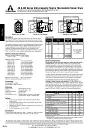
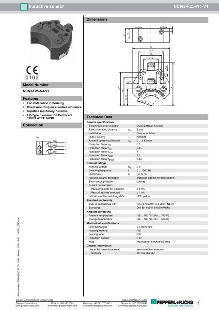
<strong>Inductive</strong> <strong>sensor</strong><br />
<strong>NCN3</strong>-<strong>F25</strong>-<strong>N4</strong>-<strong>V1</strong><br />
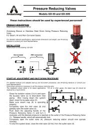
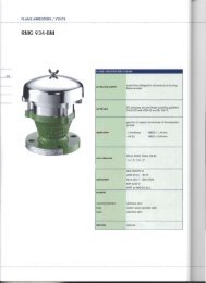
Dimensions<br />
5<br />
20<br />
15<br />
52<br />
35,4<br />
30<br />
21,2<br />
M12x1<br />
4,3<br />
Release date: 2008-09-30 12:19 Date of issue: 2008-10-08 106315_ENG.xml<br />
0102<br />
Model Number<br />
<strong>NCN3</strong>-<strong>F25</strong>-<strong>N4</strong>-<strong>V1</strong><br />
Features<br />
• For installation in housing<br />
• Direct mounting on standard actuators<br />
• Satisfies machinery directive<br />
• EC-Type Examination Certificate<br />
TÜV99 ATEX 1479X<br />
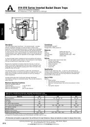
Connection<br />
<strong>N4</strong><br />
I<br />
II<br />
I<br />
I<br />
II<br />
1/BN<br />
3/BU<br />
2/WH<br />
4/BK<br />
+<br />
-<br />
+<br />
-<br />
Technical Data<br />
47<br />
40<br />
23,75<br />
∅5,3<br />
R 20,8<br />
General specifications<br />
Switching element function<br />
DCDual Break function<br />
Rated operating distance s n 3 mm<br />
Installation<br />
flush mountable<br />
Output polarity<br />
NAMUR<br />
Assured operating distance s a 0 ... 2.43 mm<br />
Reduction factor r Al 0.5<br />
Reduction factor r Cu 0.45<br />
Reduction factor r V2A 1<br />
Reduction factor r St37 1.1<br />
Reduction factor r Brass 0.63<br />
Nominal ratings<br />
Nominal voltage U o 8 V<br />
Switching frequency f 0 ... 1500 Hz<br />
Hysteresis H typ. 5 %<br />
Reverse polarity protection<br />
protected against reverse polarity<br />
Short-circuit protection<br />
pulsing<br />
Current consumption<br />
Measuring plate not detected ≥ 3 mA<br />
Measuring plate detected<br />
≤ 1 mA<br />
Indication of the switching state LED, yellow<br />
Standard conformity<br />
EMC in accordance with IEC / EN 60947-5-2:2004; NE 21<br />
Standards<br />
DIN EN 60947-5-6 (NAMUR)<br />
Ambient conditions<br />
Ambient temperature -25 ... 100 °C (248 ... 373 K)<br />
Storage temperature -40 ... 100 °C (233 ... 373 K)<br />
Mechanical specifications<br />
Connection type<br />
<strong>V1</strong>-connector<br />
Housing material<br />
PBT<br />
Sensing face<br />
PBT<br />
Protection degree<br />
IP67<br />
Note<br />
Mounted on mechanical drive<br />
General information<br />
Use in the hazardous area<br />
see instruction manuals<br />
Category<br />
1G; 2G; 3G; 3D<br />
45<br />
30<br />
15<br />
45°<br />
LED<br />
0<br />
15<br />
45°<br />
30<br />
5,3<br />
45<br />
61<br />
Subject to modifications without notice<br />
Pepperl+Fuchs Group<br />
www.pepperl-fuchs.com<br />
USA: +1 330 486 0001<br />
fa-info@us.pepperl-fuchs.com<br />
Germany: +49 621 776-4411<br />
fa-info@de.pepperl-fuchs.com<br />
Copyright Pepperl+Fuchs<br />
Singapore: +65 6779 9091<br />
fa-info@sg.pepperl-fuchs.com<br />
1
<strong>Inductive</strong> <strong>sensor</strong><br />
<strong>NCN3</strong>-<strong>F25</strong>-<strong>N4</strong>-<strong>V1</strong><br />
ATEX 1G<br />
Instruction<br />
Manual electrical apparatus for hazardous areas<br />
Device category 1G<br />
for use in hazardous areas with gas, vapour and mist<br />
Directive conformity<br />
94/9/EG<br />
Standard conformity EN 50014:1997, EN 50020:2002, EN 50284:1999<br />
Ignition protection "Intrinsic safety"<br />
Use is restricted to the following stated conditions<br />
CE symbol 0102<br />
Ex-identification<br />
EC-Type Examination Certificate<br />
Appropriate type<br />
Effective internal capacitance C i<br />
Effective internal inductance L i<br />
General<br />
Highest permissible ambient temperature<br />
Installation, Comissioning<br />
Maintenance<br />
Special conditions<br />
Protection from mechanical danger<br />
Electrostatic charging<br />
¬ II 1G EEx ia IIC T6<br />
TÜV 99 ATEX 1479 X<br />
<strong>NCN3</strong>-<strong>F25</strong>.-<strong>N4</strong>...<br />
≤ 100 nF A cable length of 10 m is considered.<br />
The value is applicable for the <strong>sensor</strong> circuit.<br />
≤ 100 µH A cable length of 10 m is considered.<br />
The value is applicable for the <strong>sensor</strong> circuit.<br />
The apparatus has to be operated according to the appropriate data in the data<br />
sheet and in this instruction manual.<br />
The EC-Type Examination Certificate has to be observed. The special conditions<br />
must be adhered to!<br />
Directive 94/9EG and hence also EC-Type Examination Certificates apply in<br />
general only to the use of electrical apparatus under atmospheric conditions.<br />
The use in ambient temperatures of > 60 °C was tested with regard to hot surfaces<br />
by the mentioned certification authority.<br />
If the equipment is not used under atmospheric conditions, a reduction of the<br />
permissible minimum ignition energies may have to be taken into consideration.<br />
The temperature ranges, according to temperature class, are given in the EC-<br />
Type Examination Certificate. Note: Use the temperature table for category 1 !!!<br />
The 20 % reduction in accordance with EN 1127-1:1997 has already been<br />
accounted for in the temperature table for category 1.<br />
Laws and/or regulations and standards governing the use or intended usage<br />
goal must be observed.<br />
The intrinsic safety is only assured in connection with an appropriate related<br />
apparatus and according to the proof of intrinsic safety.<br />
The associated apparatus must satisfy the requirements of category ia.<br />
Due to the possible danger of ignition, which can arise due to faults and/or transient<br />
currents in the equipotential bonding system, galvanic isolation of the<br />
power supply and signal circuit is preferable. Associated apparatus without electrical<br />
isolation must only be used if the appropriate requirements of IEC 60079-<br />
14 are met.<br />
No changes can be made to apparatus, which are operated in hazardous areas.<br />
Repairs to these apparatus are not possible.<br />
When used in the temperature range below -20 °C the <strong>sensor</strong> should be protected<br />
from knocks by the provision of an additional housing.<br />
When used in group IIC non-permissible electrostatic charges should be avoided<br />
on the plastic housing parts.<br />
Release date: 2008-09-30 12:19 Date of issue: 2008-10-08 106315_ENG.xml<br />
2<br />
Subject to modifications without notice<br />
Pepperl+Fuchs Group<br />
www.pepperl-fuchs.com<br />
USA: +1 330 486 0001<br />
fa-info@us.pepperl-fuchs.com<br />
Germany: +49 621 776-4411<br />
fa-info@de.pepperl-fuchs.com<br />
Copyright Pepperl+Fuchs<br />
Singapore: +65 6779 9091<br />
fa-info@sg.pepperl-fuchs.com
<strong>Inductive</strong> <strong>sensor</strong><br />
<strong>NCN3</strong>-<strong>F25</strong>-<strong>N4</strong>-<strong>V1</strong><br />
ATEX 2G<br />
Instruction<br />
Manual electrical apparatus for hazardous areas<br />
Device category 2G<br />
for use in hazardous areas with gas, vapour and mist<br />
Directive conformity<br />
94/9/EG<br />
Standard conformity EN 50014:1997, EN 50020:2002<br />
Ignition protection "Intrinsic safety"<br />
Use is restricted to the following stated conditions<br />
CE symbol 0102<br />
Ex-identification<br />
EC-Type Examination Certificate<br />
Appropriate type<br />
Effective internal capacitance C i<br />
Effective internal inductance L i<br />
General<br />
Highest permissible ambient temperature<br />
Installation, Comissioning<br />
¬ II 1G EEx ia IIC T6<br />
TÜV 99 ATEX 1479 X<br />
<strong>NCN3</strong>-<strong>F25</strong>.-<strong>N4</strong>...<br />
≤ 100 nF ; a cable length of 10 m is considered. The value is applicable for the<br />
<strong>sensor</strong> circuit.<br />
≤ 100 µH ; a cable length of 10 m is considered. The value is applicable for the<br />
<strong>sensor</strong> circuit.<br />
The apparatus has to be operated according to the appropriate data in the data<br />
sheet and in this instruction manual. The EC-Type Examination Certificate has<br />
to be observed. The special conditions must be adhered to!<br />
Directive 94/9EG and hence also EC-Type Examination Certificates apply in<br />
general only to the use of electrical apparatus under atmospheric conditions.<br />
The use in ambient temperatures of > 60 °C was tested with regard to hot surfaces<br />
by the mentioned certification authority.<br />
If the equipment is not used under atmospheric conditions, a reduction of the<br />
permissible minimum ignition energies may have to be taken into consideration.<br />
The temperature ranges, according to temperature class, are given in the EC-<br />
Type Examination Certificate.<br />
Laws and/or regulations and standards governing the use or intended usage<br />
goal must be observed. The intrinsic safety is only assured in connection with<br />
an appropriate related apparatus and according to the proof of intrinsic safety.<br />
Maintenance<br />
Special conditions<br />
Protection from mechanical danger<br />
No changes can be made to apparatus, which are operated in hazardous areas.<br />
Repairs to these apparatus are not possible.<br />
When used in the temperature range below -20 °C the <strong>sensor</strong> should be protected<br />
from knocks by the provision of an additional housing.<br />
Release date: 2008-09-30 12:19 Date of issue: 2008-10-08 106315_ENG.xml<br />
Subject to modifications without notice<br />
Pepperl+Fuchs Group<br />
www.pepperl-fuchs.com<br />
USA: +1 330 486 0001<br />
fa-info@us.pepperl-fuchs.com<br />
Germany: +49 621 776-4411<br />
fa-info@de.pepperl-fuchs.com<br />
Copyright Pepperl+Fuchs<br />
Singapore: +65 6779 9091<br />
fa-info@sg.pepperl-fuchs.com<br />
3
<strong>Inductive</strong> <strong>sensor</strong><br />
<strong>NCN3</strong>-<strong>F25</strong>-<strong>N4</strong>-<strong>V1</strong><br />
ATEX 3D<br />
Note<br />
Instruction<br />
This instruction is only valid for products according to EN 50281-1-1, valid until 30-September-2008<br />
Note the ex-marking on the <strong>sensor</strong> or on the enclosed adhesive label<br />
Manual electrical apparatus for hazardous areas<br />
Device category 3D<br />
for use in hazardous areas with non-conducting combustible dust<br />
Directive conformity<br />
94/9/EG<br />
Standard conformity EN 50281-1-1<br />
Protection via housing<br />
Use is restricted to the following stated conditions<br />
CE symbol 0102<br />
Ex-identification<br />
General<br />
Installation, Comissioning<br />
Maintenance<br />
Special conditions<br />
Minimum series resistance R V<br />
Maximum operating voltage UBmax<br />
¬ II 3D IP67 T 111 °C X<br />
The apparatus has to be operated according to the appropriate data in the data sheet and in this instruction manual.<br />
The data stated in the data sheet are restricted by this operating instruction! The special conditions must be adhered to!<br />
Laws and/or regulations and standards governing the use or intended usage goal must be observed. Each <strong>sensor</strong> circuit<br />
van be operated with the stated maximum values.<br />
No changes can be made to apparatus, which are operated in hazardous areas.<br />
Repairs to these apparatus are not possible.<br />
A minimum series resistance RV is to be provided between the power supply voltage and the proximity switch in accordance<br />
with the following list. This can also be assured by using a switch amplifier.<br />
The maximum permissible operating voltage UBmax must be restricted to the values given in the following list. Tolerances<br />
are not permitted.<br />
Maximum heating (Temperature rise) Values can be obtained from the following list, depending on the max. operating voltage Ub max and the minimum<br />
series resistance Rv.<br />
at U Bmax =9 V, R V =562 Ω 11 °C<br />
using an amplifier in accordance with 11 °C<br />
EN 60947-5-6<br />
Plug connector<br />
The plug connector must not be disconnected under voltage. The proximity switch is marked as follows: “DO NOT DIS-<br />
CONNECT UNDER VOLTAGE!” When the plug connector is disconnected the ingress of dirt into the inner areas (i.e.<br />
the areas, which are not accessible in the plugged-in condition) must be prevented.<br />
The plug connection can only be separated using a tool. This is achieved by using the locking protection <strong>V1</strong>-Clip (Mounting<br />
accessory from Pepperl + Fuchs).<br />
Protection from mechanical danger<br />
The <strong>sensor</strong> must not be mechanically damaged.<br />
Release date: 2008-09-30 12:19 Date of issue: 2008-10-08 106315_ENG.xml<br />
4<br />
Subject to modifications without notice<br />
Pepperl+Fuchs Group<br />
www.pepperl-fuchs.com<br />
USA: +1 330 486 0001<br />
fa-info@us.pepperl-fuchs.com<br />
Germany: +49 621 776-4411<br />
fa-info@de.pepperl-fuchs.com<br />
Copyright Pepperl+Fuchs<br />
Singapore: +65 6779 9091<br />
fa-info@sg.pepperl-fuchs.com
<strong>Inductive</strong> <strong>sensor</strong><br />
<strong>NCN3</strong>-<strong>F25</strong>-<strong>N4</strong>-<strong>V1</strong><br />
ATEX 3D (tD)<br />
Note This instruction is only valid for products according to EN 61241-0:2006 and EN 61241-1:2004<br />
Note the ex-marking on the <strong>sensor</strong> or on the enclosed adhesive label<br />
Instruction<br />
Manual electrical apparatus for hazardous areas<br />
Device category 3D<br />
for use in hazardous areas with non-conducting combustible dust<br />
Directive conformity<br />
94/9/EG<br />
Standard conformity EN 61241-0:2006, EN 61241-1:2004<br />
Protection via housing "tD"<br />
Use is restricted to the following stated conditions<br />
CE symbol<br />
Ex-identification<br />
General<br />
Installation, Comissioning<br />
Maintenance<br />
Special conditions<br />
Minimum series resistance R V<br />
Maximum operating voltage UBmax<br />
¬ II 3D Ex tD A22 IP67 T80°C X<br />
The apparatus has to be operated according to the appropriate data in the data sheet and in this instruction manual.<br />
The maximum surface temperature has been determined in accordance with method A without a dust layer on the<br />
equipment.<br />
The data stated in the data sheet are restricted by this operating instruction!<br />
The special conditions must be adhered to!<br />
Laws and/or regulations and standards governing the use or intended usage goal must be observed. Each <strong>sensor</strong> circuit<br />
van be operated with the stated maximum values.<br />
No changes can be made to apparatus, which are operated in hazardous areas.<br />
Repairs to these apparatus are not possible.<br />
A minimum series resistance RV is to be provided between the power supply voltage and the proximity switch in accordance<br />
with the following list. This can also be assured by using a switch amplifier.<br />
The maximum permissible operating voltage UBmax must be restricted to the values given in the following list. Tolerances<br />
are not permitted.<br />
Maximum permissible ambient tempera-Valueture series resistance Rv.<br />
can be obtained from the following list, depending on the max. operating voltage Ub max and the minimum<br />
at U Bmax =9 V, R V =562 Ω 59 °C<br />
using an amplifier in accordance with 59 °C<br />
EN 60947-5-6<br />
Plug connector<br />
The plug connector must not be withdrawn under voltage. The proximity switch is identified as follows: "WARNING - DO<br />
NOT SEPARATE WHEN ENERGIZED". With the plug connector disconnected, soiling of the internal area must be prevented.(i.e.<br />
the area that is inaccessible when the connector is inserted)<br />
The plug connection can only be separated using a tool. This is achieved by using the locking protection <strong>V1</strong>-Clip (Mounting<br />
accessory from Pepperl + Fuchs).<br />
Protection from mechanical danger<br />
Protection from UV light<br />
The <strong>sensor</strong> must not be exposed to ANY FORM of mechanical danger.<br />
The <strong>sensor</strong> and the connection cable must be protected from damaging UV-radiation. This can be achieved when the<br />
<strong>sensor</strong> is used in internal areas.<br />
Release date: 2008-09-30 12:19 Date of issue: 2008-10-08 106315_ENG.xml<br />
Subject to modifications without notice<br />
Pepperl+Fuchs Group<br />
www.pepperl-fuchs.com<br />
USA: +1 330 486 0001<br />
fa-info@us.pepperl-fuchs.com<br />
Germany: +49 621 776-4411<br />
fa-info@de.pepperl-fuchs.com<br />
Copyright Pepperl+Fuchs<br />
Singapore: +65 6779 9091<br />
fa-info@sg.pepperl-fuchs.com<br />
5
<strong>Inductive</strong> <strong>sensor</strong><br />
<strong>NCN3</strong>-<strong>F25</strong>-<strong>N4</strong>-<strong>V1</strong><br />
ATEX 3G (nL)<br />
Instruction<br />
Manual electrical apparatus for hazardous areas<br />
Device category 3G (nL)<br />
for use in hazardous areas with gas, vapour and mist<br />
Directive conformity<br />
94/9/EG<br />
Standard conformity<br />
EN 60079-15:2005 Ignition protection category "n"<br />
Use is restricted to the following stated conditions<br />
CE symbol 0102<br />
Ex-identification<br />
Effective internal capacitance C i<br />
¬ II 3G Ex nL IIC T6 X<br />
≤ 100 nF ; A cable length of 10 m is considered.<br />
The value is applicable for the <strong>sensor</strong> circuit.<br />
Effective internal inductance L i<br />
≤ 100 µH ; A cable length of 10 m is considered.<br />
The value is applicable for the <strong>sensor</strong> circuit.<br />
General<br />
The apparatus has to be operated according to the appropriate data in the data<br />
sheet and in this instruction manual. The data stated in the data sheet are restricted<br />
by this operating instruction!<br />
The special conditions must be observed!<br />
Directive 94/9EG is generally applicable only to the use of electrical apparatus<br />
operating at atmospheric conditions.<br />
If the equipment is not used under atmospheric conditions, a reduction of the<br />
permissible minimum ignition energies may have to be taken into consideration.<br />
Installation, Comissioning<br />
Laws and/or regulations and standards governing the use or intended usage<br />
goal must be observed. The <strong>sensor</strong> must only be operated with an energylimited<br />
circuit, which satisfies the requirements of IEC 60079-15. The explosion<br />
group complies with the connected, supplying, power limiting circuit.<br />
Maintenance<br />
No changes can be made to apparatus, which are operated in hazardous areas.<br />
Repairs to these apparatus are not possible.<br />
Special conditions<br />
Maximum permissible ambient temperature T Umax at Ui = 20 V<br />
Each <strong>sensor</strong> circuit van be operated with the stated maximum values.<br />
for Pi=34 mW, Ii=25 mA, T6 64 °C<br />
for Pi=34 mW, Ii=25 mA, T5 64 °C<br />
for Pi=34 mW, Ii=25 mA, T4-T1 64 °C<br />
for Pi=64 mW, Ii=25 mA, T6 59 °C<br />
for Pi=64 mW, Ii=25 mA, T5 59 °C<br />
for Pi=64 mW, Ii=25 mA, T4-T1 59 °C<br />
for Pi=169 mW, Ii=52 mA, T6 41 °C<br />
for Pi=169 mW, Ii=52 mA, T5 41 °C<br />
for Pi=169 mW, Ii=52 mA, T4-T1 41 °C<br />
Protection from mechanical danger<br />
The <strong>sensor</strong> must not be exposed to ANY FORM of mechanical danger. When<br />
used in the temperature range below -20 °C the <strong>sensor</strong> should be protected<br />
from knocks by the provision of an additional housing.<br />
Protection from UV light<br />
Connection parts<br />
The <strong>sensor</strong> and the connection cable must be protected from damaging UVradiation.<br />
This can be achieved when the <strong>sensor</strong> is used in internal areas.<br />
The connection parts are to be installed, such that a minimum protection class<br />
of IP20 is achieved, in accordance with IEC 60529.<br />
Release date: 2008-09-30 12:19 Date of issue: 2008-10-08 106315_ENG.xml<br />
6<br />
Subject to modifications without notice<br />
Pepperl+Fuchs Group<br />
www.pepperl-fuchs.com<br />
USA: +1 330 486 0001<br />
fa-info@us.pepperl-fuchs.com<br />
Germany: +49 621 776-4411<br />
fa-info@de.pepperl-fuchs.com<br />
Copyright Pepperl+Fuchs<br />
Singapore: +65 6779 9091<br />
fa-info@sg.pepperl-fuchs.com
<strong>Inductive</strong> <strong>sensor</strong><br />
<strong>NCN3</strong>-<strong>F25</strong>-<strong>N4</strong>-<strong>V1</strong><br />
ATEX 3G (ic)<br />
Instruction<br />
Device category 3G (ic)<br />
Directive conformity<br />
Standard conformity<br />
CE symbol<br />
Ex-identification<br />
Effective internal capacitance C i<br />
Effective internal inductance L i<br />
General<br />
Installation, Comissioning<br />
Manual electrical apparatus for hazardous areas<br />
for use in hazardous areas with gas, vapour and mist<br />
94/9/EG<br />
EN 60079-11:2007 Ignition protection category "ic"<br />
Use is restricted to the following stated conditions<br />
¬ II 3G Ex ic IIC T6 X<br />
≤ 100 nF ; a cable length of 10 m is considered. The value is applicable for the<br />
<strong>sensor</strong> circuit.<br />
≤ 100 µH ; A cable length of 10 m is considered.<br />
The value is applicable for the <strong>sensor</strong> circuit.<br />
The apparatus has to be operated according to the appropriate data in the data<br />
sheet and in this instruction manual. The data stated in the data sheet are restricted<br />
by this operating instruction!<br />
The special conditions must be observed!<br />
Directive 94/9EG is generally applicable only to the use of electrical apparatus<br />
operating at atmospheric conditions.<br />
If the equipment is not used under atmospheric conditions, a reduction of the<br />
permissible minimum ignition energies may have to be taken into consideration.<br />
Laws and/or regulations and standards governing the use or intended usage<br />
goal must be observed. The <strong>sensor</strong> must only be operated with energy-limited<br />
circuits, which satisfy the requirements of IEC 60079-11. The explosion group<br />
depends on the connected and energy-limited supply circuit.<br />
Maintenance<br />
No changes can be made to apparatus, which are operated in hazardous areas.<br />
Repairs to these apparatus are not possible.<br />
[Fett]Special conditions<br />
Maximum permissible ambient temperature T Umax at Ui = 20 V<br />
Each <strong>sensor</strong> circuit van be operated with the stated maximum values.<br />
for Pi=34 mW, Ii=25 mA, T6 64 °C<br />
for Pi=34 mW, Ii=25 mA, T5 64 °C<br />
for Pi=34 mW, Ii=25 mA, T4-T1 64 °C<br />
for Pi=64 mW, Ii=25 mA, T6 59 °C<br />
for Pi=64 mW, Ii=25 mA, T5 59 °C<br />
for Pi=64 mW, Ii=25 mA, T4-T1 59 °C<br />
for Pi=169 mW, Ii=52 mA, T6 41 °C<br />
for Pi=169 mW, Ii=52 mA, T5 41 °C<br />
for Pi=169 mW, Ii=52 mA, T4-T1 41 °C<br />
Protection from mechanical danger<br />
The <strong>sensor</strong> must not be mechanically damaged.<br />
When used in the temperature range below -20 °C the <strong>sensor</strong> should be protected<br />
from knocks by the provision of an additional housing.<br />
Connection parts<br />
The connection parts are to be installed, such that a minimum protection class<br />
of IP20 is achieved, in accordance with IEC 60529.<br />
Release date: 2008-09-30 12:19 Date of issue: 2008-10-08 106315_ENG.xml<br />
Subject to modifications without notice<br />
Pepperl+Fuchs Group<br />
www.pepperl-fuchs.com<br />
USA: +1 330 486 0001<br />
fa-info@us.pepperl-fuchs.com<br />
Germany: +49 621 776-4411<br />
fa-info@de.pepperl-fuchs.com<br />
Copyright Pepperl+Fuchs<br />
Singapore: +65 6779 9091<br />
fa-info@sg.pepperl-fuchs.com<br />
7