TYPE 5600 EP
TYPE 5600 EP
TYPE 5600 EP

Create successful ePaper yourself
Turn your PDF publications into a flip-book with our unique Google optimized e-Paper software.
UNIWORLD series ELECTRIC POWERED VALVES<br />
<strong>5600</strong><strong>EP</strong>/E<br />
07 2007<br />
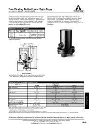
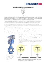
THREE-WAY MIXING CONTROL VALVES<br />
<strong>TYPE</strong> <strong>5600</strong> <strong>EP</strong><br />
with tension opens and closes AB and CB<br />
Face-to-face ASME / ANSI B16.10<br />
DESCRIPTION<br />
The “UNIWORLD” series type <strong>5600</strong> <strong>EP</strong> are equipped with<br />
“straight-through” pattern bodies having ANSI face-to-face<br />
dimensions and EN – ANSI – JIS flanges.<br />
Type <strong>5600</strong> <strong>EP</strong> three-way mixing control valves (two inlet ports and<br />
one outlet port with fluid opens) have a modulating plug suitable for<br />
control of virtually all line media.<br />
Compact construction assembled with “made in Germany” linear<br />
electric actuator fixed to the body by means of two steel columns.<br />
The electric actuator works with standard 3 points modulating control<br />
signal or can be equipped with a potentiometer and with a pilot<br />
positioner having 0 (4) - 20 mA or 0 (2) - 10 V control signal.<br />
SIZES : from DN 15 to DN 200 TECHNICAL CHARACTERISTICS OF ELECTRIC ACTUATOR :<br />
BODY CONNECTIONS : flanged EN 1092-1 PN16 PN40 • Standard power supply : 220 V AC<br />
flanged ANSI B 16.5 150 RF 300 RF • Degree of protection : IP 65 DIN 40050<br />
flanged JIS B2220 10K 20K • Control signal : 3 points modulating input<br />
• Ambient temperature : -20 ... +60 °C<br />
MATERIALS OF BODY GROUP (1) : • Actuator case material : die cast aluminium<br />
• Cast iron EN-GJL-250 UNI EN 1561 PN 16 ANSI 150 JIS10<br />
• Actuator cover material : polycarbonate<br />
AISI 316 st. st. trim - C40 nickel plated steel bonnet<br />
• Manual handwheel<br />
: standard included<br />
• Carbon steel ASTM A216 WCB PN16/40 ANSI 150/300 JIS10/20 • Electric connections : cable gland PG13 (2 off)<br />
AISI 316 st. st. trim - C40 nickel plated steel bonnet<br />
• Stainless steel AISI 316 CF8M PN16/40 ANSI 150/300 JIS10/20<br />
AISI 316 st. st. trim - AISI 316 st. st. bonnet MAX WORKING CONDITIONS :<br />
• Max inlet pressure and temperature : see leaflet n° 101/VP<br />
PLUG • Valve sizing : see leaflet n° 100/VP<br />
• PL (DN15-20) LV (DN25-200) = linear class IV° • Rangeability : see leaflet n° GRAFICI/I<br />
• PT (DN15-20) VPT (DN25-200) = quick lift class IV°<br />
ON REQUEST :<br />
BONNET (2) : • Lapping on seat and plug class V°<br />
Standard : -5 to + 200 °C • Stellite (degree 6°) on seat and plug<br />
Finned : > 200 °C • Stellite (degree 6°) on guide bush<br />
Extended : below - 5 °C • Power supply 24 V DC – 24 V AC – 110 V AC<br />
Bellows sealed : for thermal oil or hazardous media with<br />
(PN 16 - 25 - 40) standard safety gland arrangement<br />
• Potentiometer 1000 Ohm, simple or double<br />
• Positioner 0 (4)–20 mA … 0 (2)–10 V, 2 wires, c/w potentiometer<br />
• Card with mechanical limit switches<br />
GLAND ARRANGEMENT (PACKING) (3) with safety “0-rings” : • Card for 4-20 mA feedback signal (2 wires system)<br />
• PTFE 100% for temperatures ≤150 °C • IP 67 DIN 40050 protection<br />
• PTFE 85% + GRAPHITE 15% for temperatures ≤ 200 °C • Heating resistor for ambient temperature up-to - 30 °C<br />
• PURE GRAPHITE 100% for temperatures from 200° to 400 °C<br />
to be used with finned bonnet<br />
CV = american unit (flowrate in USGPM<br />
with 1 psi of differential pressure)<br />
Kv = metric unit (flowrate in m3/h<br />
with 1 bar of differential pressure)<br />
PLUG DN15 DN 20 DN25 DN32 DN40 DN50 DN65 DN80 DN100 DN125 DN150 DN200<br />
Full bore Ø 1/2” Ø 3/4” Ø 1” Ø 1.1/4” Ø 1.1/2” Ø 2” Ø 2.1/2” Ø 3” Ø 4” Ø 5” Ø 6” Ø 8”<br />
PL CV 3.4 6.6 10 23.4 28 36.4 72.7 89.3 123.8 290.9 357.3 578.1<br />
KV 2.9 5.7 8.6 20.1 24.1 31.4 62.7 77 106.7 250.8 308 498.3<br />
CV<br />
PT<br />
3.4 6.6 13.8 30.3 38.7 52 99.6 116.2 162.4 355.3 429.8 658.6<br />
KV 2.9 5.7 11.9 26.1 33.4 44.8 85.8 100.1 140 306.3 370.5 567.7<br />
Reduced bore * n.a. ½” ½” ¾” ¾” 1” 1” 1.1/4” 1.1/4” 1.1/2” 1.1/2” 2” 2” 2.1/2” 2.1/2” 3” 3” 4” 4” 5” 5” 6”<br />
n.a. = not applicable<br />
* CV and KV values are referred to the selected diameter and plug type (PL/LV only)<br />
Via Lecco, 69/71<br />
20041 AGRATE BRIANZA (MI)<br />
Tel. 039/651.705 - 650.397<br />
Fax 039/654.018
Maximum permissible pressure drops in Kg/cm2 (fluid opens) with alive motor<br />
Power and Current absorbed – Speed in second for total stroke in mm<br />
Actuator Type<br />
NOMINAL DIAMETER<br />
Power absorbed DN15 DN20 DN25 DN32 DN40 DN50 DN65 DN80 DN100 DN125 DN150 DN200<br />
PSL201 Kg/cm2 50 31 18 12 8 4.5 - - - - - -<br />
50/60 Hz speed sec 44 44 44 76 76 76 - - - - - -<br />
26 VA stroke mm 11 11 11 19 19 19 - - - - - -<br />
PSL202 Kg/cm2 - 62 36 24 16 9 6 4 2.2 - - -<br />
50/60 Hz speed sec - 22 22 38 38 38 56 56 56 - - -<br />
37/40 VA stroke mm - 11 11 19 19 19 28 28 28 - - -<br />
PSL204 Kg/cm2 - - 85 55 38 22 13.5 9.4 5.3 - - -<br />
50/60 Hz speed sec - - 22 38 38 38 56 56 56 - - -<br />
44/47 VA stroke mm - - 11 19 19 19 28 28 28 - - -<br />
PSL210 Kg/cm2 - - - - 94 54 33.5 23.5 13 - - -<br />
50/60 Hz speed sec - - - - 38 57 84 84 84 - - -<br />
72/68 VA stroke mm - - - - 19 19 28 28 28 - - -<br />
PSL312 Kg/cm2 - - - - - - - - - 9.5 6.5 3.8<br />
50/60 Hz speed sec - - - - - - - - - 84 84 84<br />
88/73 VA stroke mm - - - - - - - - - 50 50 50<br />
1. The values given are referred to the force of the actuator abd they can be used within the limit of the body rating.<br />
2. Electric actuators suitable for operating force up-to 25 kN are available on request.<br />
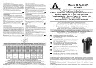
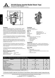
COMPONENTS LIST and MATERIALS<br />
COMPONENTS LIST<br />
1. Body<br />
1a Stud pipe<br />
2. Upper seat<br />
2a Lower seat<br />
3. Plug locknuts<br />
4. Spring washer<br />
5. Plug<br />
6. Stem<br />
7. Bonnet<br />
8. Guide bush<br />
9. Body gasket<br />
10. Packing spring<br />
11. Packing washer<br />
12. Packing rings<br />
13. Internal “O” ring<br />
14. External “O”<br />
15. Packing adjusting nut<br />
16. Stud-bolts<br />
17. Body locknuts<br />
18. Upper bonnet flange<br />
19. Travel indicator plate<br />
20. Column fixing screwes<br />
21. Actuator columns<br />
22. Grub screw<br />
23. Electric actuator<br />
BONNET DETAILS<br />
MATERIALS<br />
1. See note (1) at page 1<br />
1a C40 carbon steel<br />
2. AISI 316 stainless steel<br />
2a AISI 316 stainless steel<br />
3. AISI 304 stainless steel<br />
4. AISI 304 stainless steel<br />
5. AISI 316 stainless steel<br />
6. AISI 316 stainless steel<br />
7. See notes (1)(2) at page 1<br />
8. AISI 304 stainless steel<br />
9. Europil WS 3640 or<br />
PTFE on request<br />
10. AISI 302 stainless steel<br />
11. AISI 304 stainless steel<br />
12. See note (3) at page 1<br />
13. Viton FPM 70<br />
14. Viton FPM 70<br />
15. AISI 303 stainless steel<br />
16. Galvanized steel<br />
17. DIN 934 galvanized steel<br />
18. C40 nickel plated steel<br />
19. Polycarbonate<br />
20. DIN 912 galvanized steel<br />
21. AISI 430 stainless steel<br />
22. DIN 914 galvanized steel<br />
23. See technical data at<br />
page 1<br />
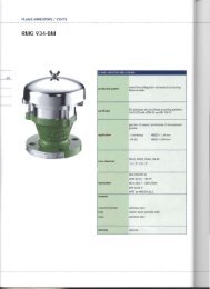
DIMENSIONS in mm.<br />
BODY GROUP<br />
ACTUATOR<br />
DN Ø A(1) A(2) B<br />
C - Bonnet PSL201-202-204-210 PSL312<br />
Std Finned Bellows Ø D E F ØD E<br />
15 1/2” 184 196 131 49 181 181 176 410 50 - -<br />
20 3/4” 184 196 134 58 190 190 176 410 50 - -<br />
25 1” 184 196 135 68 200 200 176 410 50 - -<br />
32 1.1/4” 200 212 134 70 202 202 176 410 50 - -<br />
40 1.1/2” 222 234 165 82 214 214 176 410 50 - -<br />
50 2” 254 266 185 86 218 218 176 410 50 - -<br />
65 2.1/2” 276 292 220 111 309 309 176 417 50 - -<br />
80 3” 298 317 222 135 333 333 176 417 50 - -<br />
100 4” 352 368 241 160 363 363 176 419 50 - -<br />
125 5 403 425 296 252 435 435 176 430 50 226 530<br />
150 6” 450 472 307 258 442 442 176 430 50 226 530<br />
200 8” 543 568 333 283 465 465 176 430 50 226 530<br />
A(1) cast iron = PN16 – ANSI150 – JIS10K<br />
Specifications given are only indicative and not binding for<br />
A(2) carbon and st. steel = PN16 – PN40 - ANSI150 – ANSI300<br />
JIS10K – JIS20K<br />
the manufacturer who reserve the right to carry-out any<br />
modification deemed necessary without prior notice