Steam Humidifiers in Central Systems, continued⦠- Klinger ...
Steam Humidifiers in Central Systems, continued⦠- Klinger ...
Steam Humidifiers in Central Systems, continued⦠- Klinger ...

Create successful ePaper yourself
Turn your PDF publications into a flip-book with our unique Google optimized e-Paper software.
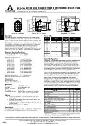
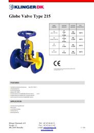
Humidity Content Tables<br />
Humidification<br />
Eng<strong>in</strong>eer<strong>in</strong>g Guidel<strong>in</strong>es<br />
Dry bulb<br />
temp.<br />
<strong>in</strong> °C<br />
Vapour<br />
pressure<br />
<strong>in</strong> Pa<br />
Specific<br />
steam<br />
vol. <strong>in</strong><br />
m³/kg<br />
Specific<br />
air vol.<br />
<strong>in</strong> m³/kg<br />
Relative Humidity (RH)<br />
5% 10% 15% 20% 25% 30% 35% 40% 45% 50% 55% 60% 65% 70% 75% 80% 85% 90% 95% 100%<br />
-25 63,29 1811,43 0,7023 0,02 0,04 0,06 0,08 0,10 0,12 0,14 0,16 0,17 0,19 0,21 0,23 0,25 0,27 0,29 0,31 0,33 0,35 0,37 0,39<br />
-20 103,26 1132,63 0,7165 0,03 0,06 0,10 0,13 0,16 0,19 0,22 0,25 0,29 0,32 0,35 0,38 0,41 0,44 0,48 0,51 0,54 0,57 0,60 0,63<br />
-15 165,30 721,51 0,7308 0,05 0,10 0,15 0,20 0,25 0,30 0,36 0,41 0,46 0,51 0,56 0,61 0,66 0,71 0,76 0,81 0,86 0,91 0,97 1,02<br />
-10 259,90 467,78 0,7450 0,08 0,16 0,24 0,32 0,40 0,48 0,56 0,64 0,72 0,80 0,88 0,96 1,04 1,12 1,20 1,28 1,36 1,44 1,52 1,60<br />
-9 283,93 429,81 0,7478 0,09 0,17 0,26 0,35 0,44 0,52 0,61 0,70 0,79 0,87 0,96 1,05 1,13 1,22 1,31 1,40 1,48 1,57 1,66 1,75<br />
-8 309,98 395,18 0,7507 0,10 0,19 0,29 0,38 0,48 0,57 0,67 0,76 0,86 0,95 1,05 1,14 1,24 1,33 1,43 1,53 1,62 1,72 1,81 1,91<br />
-7 338,19 363,59 0,7535 0,10 0,21 0,31 0,42 0,52 0,62 0,73 0,83 0,94 1,04 1,14 1,25 1,35 1,46 1,56 1,67 1,77 1,87 1,98 2,08<br />
-6 368,74 334,72 0,7563 0,11 0,23 0,34 0,45 0,57 0,68 0,79 0,91 1,02 1,13 1,25 1,36 1,47 1,59 1,70 1,82 1,93 2,04 2,16 2,27<br />
-5 401,76 308,36 0,7592 0,12 0,25 0,37 0,49 0,62 0,74 0,86 0,99 1,11 1,24 1,36 1,48 1,61 1,73 1,86 1,98 2,10 2,23 2,35 2,48<br />
-4 437,47 284,24 0,7620 0,13 0,27 0,40 0,54 0,67 0,81 0,94 1,08 1,21 1,35 1,48 1,62 1,75 1,89 2,02 2,16 2,29 2,43 2,56 2,70<br />
-3 476,06 262,17 0,7649 0,15 0,29 0,44 0,59 0,73 0,88 1,02 1,17 1,32 1,46 1,61 1,76 1,91 2,05 2,20 2,35 2,49 2,64 2,79 2,94<br />
-2 517,73 241,97 0,7677 0,16 0,32 0,48 0,64 0,80 0,95 1,11 1,27 1,43 1,59 1,75 1,91 2,07 2,23 2,39 2,55 2,71 2,87 3,03 3,19<br />
-1 562,67 223,46 0,7705 0,17 0,35 0,52 0,69 0,86 1,04 1,21 1,38 1,56 1,73 1,91 2,08 2,25 2,43 2,60 2,78 2,95 3,12 3,30 3,47<br />
0 611,15 206,49 0,7734 0,19 0,38 0,56 0,75 0,94 1,13 1,32 1,50 1,69 1,88 2,07 2,26 2,45 2,64 2,83 3,02 3,21 3,39 3,58 3,77<br />
1 657,10 192,75 0,7762 0,20 0,40 0,61 0,81 1,01 1,21 1,41 1,62 1,82 2,02 2,23 2,43 2,63 2,84 3,04 3,24 3,45 3,65 3,86 4,06<br />
2 706,00 180,06 0,7791 0,22 0,43 0,65 0,87 1,09 1,30 1,52 1,74 1,96 2,17 2,39 2,61 2,83 3,05 3,27 3,49 3,71 3,92 4,14 4,36<br />
3 758,00 168,31 0,7819 0,23 0,47 0,70 0,93 1,17 1,40 1,63 1,87 2,10 2,34 2,57 2,80 3,04 3,27 3,51 3,74 3,98 4,22 4,45 4,69<br />
4 813,50 157,40 0,7848 0,25 0,50 0,75 1,00 1,25 1,50 1,75 2,00 2,26 2,51 2,76 3,01 3,26 3,52 3,77 4,02 4,27 4,53 4,78 5,03<br />
5 872,50 147,28 0,7876 0,27 0,54 0,80 1,07 1,34 1,61 1,88 2,15 2,42 2,69 2,96 3,23 3,50 3,77 4,04 4,31 4,59 4,86 5,13 5,40<br />
6 935,30 137,89 0,7904 0,29 0,57 0,86 1,15 1,44 1,73 2,02 2,31 2,59 2,88 3,17 3,46 3,75 4,05 4,34 4,63 4,92 5,21 5,50 5,79<br />
7 1 002,0 129,17 0,7933 0,31 0,62 0,92 1,23 1,54 1,85 2,16 2,47 2,78 3,09 3,40 3,71 4,02 4,34 4,65 4,96 5,27 5,59 5,90 6,21<br />
8 1 072,8 121,08 0,7961 0,33 0,66 0,99 1,32 1,65 1,98 2,31 2,65 2,98 3,31 3,64 3,98 4,31 4,64 4,98 5,31 5,65 5,98 6,32 6,66<br />
9 1 148,1 113,54 0,7990 0,35 0,71 1,06 1,41 1,77 2,12 2,48 2,83 3,19 3,54 3,90 4,26 4,61 4,97 5,33 5,69 6,05 6,41 6,77 7,13<br />
10 1 228,0 106,53 0,8018 0,38 0,75 1,13 1,51 1,89 2,27 2,65 3,03 3,41 3,79 4,17 4,56 4,94 5,32 5,71 6,09 6,47 6,86 7,24 7,63<br />
11 1 312,7 100,01 0,8046 0,40 0,81 1,21 1,62 2,02 2,43 2,83 3,24 3,65 4,06 4,46 4,87 5,28 5,69 6,10 6,51 6,93 7,34 7,75 8,16<br />
12 1 402,6 93,93 0,8075 0,43 0,86 1,29 1,73 2,16 2,59 3,03 3,46 3,90 4,33 4,77 5,21 5,65 6,09 6,53 6,96 7,41 7,85 8,29 8,73<br />
13 1 497,8 88,26 0,8103 0,46 0,92 1,38 1,84 2,31 2,77 3,23 3,70 4,17 4,63 5,10 5,57 6,03 6,50 6,97 7,44 7,91 8,39 8,86 9,33<br />
14 1 498,7 88,52 0,8132 0,46 0,92 1,38 1,85 2,31 2,77 3,24 3,70 4,17 4,63 5,10 5,57 6,04 6,51 6,98 7,45 7,92 8,39 8,86 9,34<br />
15 1 705,5 78,06 0,8160 0,52 1,05 1,57 2,10 2,63 3,16 3,69 4,22 4,75 5,28 5,81 6,35 6,88 7,42 7,95 8,49 9,03 9,57 10,10 10,60<br />
16 1 818,4 73,46 0,8188 0,56 1,12 1,68 2,24 2,80 3,37 3,93 4,50 5,06 5,63 6,20 6,77 7,34 7,91 8,49 9,06 9,63 10,20 10,80 11,40<br />
17 1 938,0 69,17 0,8217 0,60 1,19 1,79 2,39 2,99 3,59 4,19 4,80 5,40 6,01 6,61 7,22 7,83 8,44 9,05 9,66 10,30 10,90 11,50 12,10<br />
18 2 064,3 65,16 0,8245 0,63 1,27 1,91 2,54 3,18 3,82 4,47 5,11 5,75 6,40 7,05 7,70 8,35 9,00 9,65 10,30 11,00 11,60 12,30 12,90<br />
19 2 197,8 61,41 0,8274 0,68 1,35 2,03 2,71 3,39 4,07 4,76 5,44 6,13 6,82 7,51 8,20 8,89 9,59 10,30 11,00 11,70 12,40 13,10 13,80<br />
20 2 338,8 57,91 0,8302 0,72 1,44 2,16 2,88 3,61 4,34 5,07 5,80 6,53 7,26 8,00 8,73 9,47 10,20 11,00 11,70 12,40 13,20 13,90 14,70<br />
21 2 487,7 54,63 0,8330 0,76 1,53 2,30 3,07 3,84 4,62 5,39 6,17 6,95 7,73 8,51 9,30 10,10 10,90 11,70 12,50 13,30 14,10 14,90 15,70<br />
22 2 644,8 51,56 0,8359 0,81 1,63 2,44 3,26 4,09 4,91 5,73 6,56 7,39 8,22 9,06 9,90 10,70 11,60 12,40 13,30 14,10 15,00 15,80 16,70<br />
23 2 810,4 48,68 0,8387 0,86 1,73 2,60 3,47 4,34 5,22 6,10 6,98 7,86 8,75 9,64 10,50 11,40 12,30 13,20 14,10 15,00 15,90 16,80 17,70<br />
24 2 985,1 45,99 0,8416 0,92 1,84 2,76 3,69 4,61 5,55 6,48 7,42 8,36 9,30 10,20 11,20 12,10 13,10 14,10 15,00 16,00 16,90 17,90 18,90<br />
25 3 169,2 43,46 0,8444 0,97 1,95 2,93 3,92 4,90 5,89 6,88 7,88 8,88 9,88 10,90 11,90 12,90 13,90 14,90 16,00 17,00 18,00 19,00 20,10<br />
26 3 363,1 41,10 0,8472 1,03 2,07 3,11 4,16 5,20 6,26 7,31 8,37 9,43 10,50 11,60 12,60 13,70 14,80 15,90 17,00 18,10 19,20 20,30 21,40<br />
27 3 567,3 38,87 0,8501 1,10 2,20 3,30 4,41 5,52 6,64 7,76 8,88 10,00 11,10 12,30 13,40 14,60 15,70 16,90 18,00 19,20 20,40 21,50 22,70<br />
28 3 782,2 36,79 0,8529 1,16 2,33 3,50 4,68 5,86 7,04 8,23 9,43 10,60 11,80 13,00 14,20 15,50 16,70 17,90 19,10 20,40 21,60 22,90 24,10<br />
29 4 008,3 34,83 0,8558 1,23 2,47 3,71 4,96 6,21 7,47 8,73 10,00 11,30 12,60 13,80 15,10 16,40 17,70 19,00 20,30 21,60 23,00 24,30 25,60<br />
30 4 246,0 32,99 0,8586 1,31 2,62 3,93 5,26 6,58 7,92 9,26 10,60 12,00 13,30 14,70 16,00 17,40 18,80 20,20 21,60 23,00 24,40 25,80 27,20<br />
31 4 495,9 31,25 0,8614 1,38 2,77 4,17 5,57 6,98 8,39 9,81 11,20 12,70 14,10 15,60 17,00 18,50 19,90 21,40 22,90 24,40 25,90 27,40 28,90<br />
32 4 758,5 29,63 0,8643 1,46 2,93 4,41 5,90 7,39 8,89 10,40 11,90 13,40 15,00 16,50 18,00 19,60 21,10 22,70 24,30 25,90 27,40 29,00 30,60<br />
33 5 034,3 28,10 0,8671 1,55 3,11 4,67 6,24 7,82 9,41 11,00 12,60 14,20 15,80 17,50 19,10 20,80 22,40 24,10 25,70 27,40 29,10 30,80 32,50<br />
34 5 323,9 26,65 0,8700 1,64 3,29 4,94 6,61 8,28 9,96 11,70 13,40 15,10 16,80 18,50 20,20 22,00 23,70 25,50 27,30 29,10 30,90 32,70 34,50<br />
35 5 627,8 25,30 0,8728 1,73 3,47 5,23 6,99 8,76 10,50 12,30 14,10 15,90 17,80 19,60 21,40 23,30 25,20 27,00 28,90 30,80 32,70 34,60 36,60<br />
36 5 946,6 24,02 0,8756 1,83 3,67 5,52 7,39 9,26 11,10 13,00 15,00 16,90 18,80 20,70 22,70 24,70 26,60 28,60 30,60 32,70 34,70 36,70 38,80<br />
37 6 281,0 22,81 0,8785 1,93 3,88 5,84 7,81 9,79 11,80 13,80 15,80 17,80 19,90 22,00 24,00 26,10 28,20 30,30 32,50 34,60 36,80 38,90 41,10<br />
38 6 631,2 21,68 0,8813 2,04 4,10 6,17 8,25 10,30 12,50 14,60 16,70 18,90 21,00 23,20 25,40 27,60 29,90 32,10 34,40 36,60 38,90 41,20 43,60<br />
2<br />
Armstrong International SA • Parc Industriel des Hauts-Sarts (2 e Avenue) • 4040 Herstal • Belgium<br />
Tel.: +32 (0)4 240 90 90 • Fax: +32 (0)4 248 13 61<br />
www.armstrong.be • market<strong>in</strong>g@armstrong.be
Dry<br />
bulb<br />
temp.<br />
<strong>in</strong> °C<br />
Vapour<br />
pressure<br />
<strong>in</strong> Pa<br />
Specific<br />
steam<br />
vol. <strong>in</strong><br />
m³/kg<br />
Specific<br />
air vol. <strong>in</strong><br />
m³/kg<br />
Relative Humidity (RH)<br />
5% 10% 15% 20% 25% 30% 35% 40% 45% 50% 55% 60% 65% 70% 75% 80% 85% 90% 95% 100%<br />
39 6 998,7 20,61 0,8842 2,16 4,33 6,51 8,71 10,90 13,20 15,40 17,70 20,00 22,20 24,60 26,90 29,20 31,60 34,00 36,40 38,80 41,20 43,70 46,10<br />
40 7 383,5 19,59 0,8870 2,27 4,57 6,87 9,20 11,50 13,90 16,30 18,70 21,10 23,50 26,00 28,40 30,90 33,40 36,00 38,50 41,10 43,70 46,30 48,90<br />
41 7 786,5 18,64 0,8898 2,40 4,82 7,25 9,71 12,20 14,70 17,20 19,70 22,30 24,90 27,40 30,10 32,70 35,40 38,00 40,70 43,50 46,20 49,00 51,80<br />
42 8 208,0 17,74 0,8927 2,53 5,08 7,65 10,20 12,90 15,50 18,10 20,80 23,50 26,30 29,00 31,80 34,60 37,40 40,20 43,10 46,00 48,90 51,90 54,80<br />
43 8 649,2 16,89 0,8955 2,67 5,35 8,07 10,80 13,60 16,30 19,20 22,00 24,80 27,70 30,60 33,60 36,50 39,50 42,50 45,60 48,70 51,80 54,90 58,00<br />
44 9 110,7 16,08 0,8983 2,81 5,64 8,50 11,40 14,30 17,20 20,20 23,20 26,20 29,30 32,40 35,50 38,60 41,80 45,00 48,20 51,50 54,80 58,10 61,50<br />
45 9 493,2 15,48 0,9012 2,93 5,88 8,87 11,90 14,90 18,00 21,10 24,20 27,40 30,60 33,80 37,00 40,30 43,70 47,00 50,40 53,80 57,30 60,80 64,30<br />
46 10 097,6 14,60 0,9040 3,11 6,26 9,44 12,60 15,90 19,20 22,50 25,80 29,20 32,60 36,10 39,60 43,10 46,60 50,20 53,90 57,60 61,30 65,00 68,80<br />
47 10 624,6 13,92 0,9069 3,28 6,59 9,94 13,30 16,70 20,20 23,70 27,20 30,80 34,40 38,10 41,80 45,50 49,30 53,10 57,00 60,90 64,80 68,80 72,90<br />
48 11 175,1 13,28 0,9097 3,45 6,94 10,50 14,00 17,60 21,30 25,00 28,70 32,50 36,30 40,20 44,10 48,00 52,00 56,10 60,20 64,30 68,50 72,80 77,10<br />
49 11 750,0 12,67 0,9125 3,63 7,30 11,00 14,80 18,60 22,40 26,30 30,30 34,20 38,30 42,40 46,50 50,70 54,90 59,20 63,60 68,00 72,50 77,00 81,60<br />
50 12 349,9 12,09 0,9154 3,81 7,67 11,60 15,50 19,50 23,60 27,70 31,90 36,10 40,40 44,70 49,10 53,50 58,00 62,60 67,20 71,90 76,60 81,50 86,30<br />
51 12 975,9 11,54 0,9182 4,01 8,07 12,20 16,30 20,60 24,90 29,20 33,60 38,00 42,60 47,10 51,80 56,50 61,20 66,10 71,00 76,00 81,00 86,20 91,40<br />
52 13 629,0 11,02 0,9211 4,21 8,48 12,80 17,20 21,60 26,20 30,70 35,40 40,10 44,80 49,70 54,60 59,60 64,60 69,80 75,00 80,30 85,70 91,10 96,70<br />
53 14 310,0 10,53 0,9239 4,42 8,91 13,50 18,10 22,80 27,50 32,30 37,20 42,20 47,30 52,40 57,60 62,90 68,20 73,70 79,20 84,90 90,60 96,40 102,00<br />
54 15 020,0 10,06 0,9267 4,64 9,36 14,10 19,00 23,90 28,90 34,00 39,20 44,50 49,80 55,20 60,70 66,30 72,00 77,80 83,70 89,70 95,80 102,00 108,00<br />
55 15 759,7 9,62 0,9296 4,87 9,83 14,90 20,00 25,20 30,40 35,80 41,30 46,80 52,40 58,20 64,00 70,00 76,00 82,10 88,40 94,80 101,00 108,00 115,00<br />
56 16 530,4 9,20 0,9324 5,12 10,30 15,60 21,00 26,40 32,00 37,70 43,40 49,30 55,20 61,30 67,50 73,80 80,20 86,70 93,40 100,00 107,00 114,00 121,00<br />
57 17 333,1 8,80 0,9353 5,37 10,80 16,40 22,00 27,80 33,60 39,60 45,70 51,90 58,20 64,60 71,10 77,80 84,60 91,50 98,60 106,00 113,00 121,00 128,00<br />
58 18 169,0 8,42 0,9381 5,63 11,40 17,20 23,10 29,20 35,40 41,60 48,10 54,60 61,30 68,10 75,00 82,10 89,30 96,60 104,00 112,00 120,00 128,00 136,00<br />
59 19 038,7 8,06 0,9409 5,90 11,90 18,00 24,30 30,70 37,20 43,80 50,50 57,40 64,50 71,70 79,00 86,50 94,20 102,00 110,00 118,00 127,00 135,00 144,00<br />
60 19 944,0 7,72 0,9438 6,18 12,50 18,90 25,50 32,20 39,00 46,00 53,20 60,40 67,90 75,50 83,30 91,30 99,40 108,00 116,00 125,00 134,00 143,00 152,00<br />
61 20 885,0 7,39 0,9466 6,48 13,10 19,80 26,70 33,80 41,00 48,40 55,90 63,60 71,50 79,50 87,80 96,20 105,00 114,00 123,00 132,00 142,00 151,00 161,00<br />
62 21 864,0 7,08 0,9494 6,78 13,70 20,80 28,10 35,50 43,10 50,80 58,80 66,90 75,20 83,80 92,50 101,00 111,00 120,00 130,00 140,00 150,00 160,00 171,00<br />
63 22 882,0 6,79 0,9523 7,10 14,40 21,80 29,40 37,20 45,20 53,40 61,80 70,40 79,20 88,20 97,50 107,00 117,00 127,00 137,00 148,00 159,00 170,00 181,00<br />
64 23 940,0 6,51 0,9551 7,44 15,10 22,90 30,80 39,00 47,40 56,10 64,90 74,00 83,30 92,90 103,00 113,00 123,00 134,00 145,00 156,00 168,00 180,00 192,00<br />
65 25 040,0 6,24 0,9580 7,78 15,80 23,90 32,30 41,00 49,80 58,90 68,20 77,80 87,70 97,80 108,00 119,00 130,00 142,00 153,00 165,00 178,00 191,00 204,00<br />
66 26 180,0 5,99 0,9608 8,14 16,50 25,10 33,90 43,00 52,30 61,80 71,70 81,80 92,30 103,00 114,00 126,00 137,00 149,00 162,00 175,00 188,00 202,00 217,00<br />
67 27 366,0 5,74 0,9636 8,51 17,30 26,30 35,50 45,00 54,80 64,90 75,30 86,10 97,10 109,00 120,00 132,00 145,00 158,00 171,00 185,00 200,00 215,00 230,00<br />
68 28 596,0 5,51 0,9665 8,90 18,10 27,50 37,20 47,20 57,50 68,20 79,10 90,50 102,00 114,00 127,00 140,00 153,00 167,00 181,00 196,00 212,00 228,00 245,00<br />
69 29 873,0 5,29 0,9693 9,31 18,90 28,80 39,00 49,50 60,40 71,60 83,20 95,10 108,00 120,00 134,00 147,00 162,00 177,00 192,00 208,00 225,00 242,00 260,00<br />
70 31 198,0 5,08 0,9721 9,73 19,80 30,10 40,80 51,90 63,30 75,10 87,40 100,00 113,00 127,00 141,00 156,00 171,00 187,00 203,00 220,00 238,00 257,00 277,00<br />
71 32 572,0 4,88 0,9750 10,20 20,70 31,50 42,70 54,40 66,40 78,90 91,80 105,00 119,00 134,00 149,00 164,00 181,00 198,00 215,00 234,00 253,00 273,00 295,00<br />
72 33 997,0 4,69 0,9778 10,60 21,60 33,00 44,70 56,90 69,60 82,80 96,40 111,00 125,00 141,00 157,00 173,00 191,00 209,00 228,00 248,00 269,00 291,00 314,00<br />
73 35 475,0 4,51 0,9807 11,10 22,60 34,50 46,80 59,70 73,00 86,90 101,00 116,00 132,00 148,00 165,00 183,00 202,00 221,00 242,00 264,00 286,00 310,00 335,00<br />
74 37 006,0 4,33 0,9835 11,60 23,60 36,00 49,00 62,50 76,50 91,20 106,00 122,00 139,00 156,00 175,00 194,00 214,00 235,00 257,00 280,00 305,00 330,00 358,00<br />
75 38 592,0 4,17 0,9863 12,10 24,60 37,70 51,30 65,50 80,20 95,70 112,00 129,00 146,00 165,00 184,00 205,00 226,00 249,00 273,00 298,00 324,00 353,00 383,00<br />
76 40 263,0 4,01 0,9892 12,60 25,70 39,40 53,70 68,60 84,10 100,00 117,00 135,00 154,00 174,00 195,00 216,00 239,00 264,00 290,00 317,00 346,00 377,00 410,00<br />
77 41 938,0 3,86 0,9920 13,10 26,90 41,20 56,10 71,80 88,20 105,00 123,00 142,00 162,00 183,00 205,00 229,00 254,00 280,00 308,00 338,00 369,00 403,00 439,00<br />
78 43 700,0 3,71 0,9948 13,70 28,00 43,00 58,70 75,20 92,40 111,00 130,00 150,00 171,00 193,00 217,00 242,00 269,00 297,00 328,00 360,00 395,00 432,00 472,00<br />
79 45 524,0 3,57 0,9977 14,30 29,30 44,90 61,40 78,70 96,90 116,00 136,00 158,00 180,00 204,00 230,00 257,00 285,00 316,00 349,00 384,00 422,00 463,00 507,00<br />
80 47 412,0 3,44 1,0005 14,90 30,50 47,00 64,20 82,40 102,00 122,00 143,00 166,00 190,00 216,00 243,00 272,00 303,00 336,00 372,00 411,00 452,00 498,00 547,00<br />
81 49 364,0 3,31 1,0034 15,50 31,90 49,00 67,10 86,30 106,00 128,00 151,00 175,00 200,00 228,00 257,00 288,00 322,00 358,00 397,00 440,00 486,00 536,00 591,00<br />
82 51 384,0 3,19 1,0062 16,20 33,20 51,20 70,20 90,30 112,00 134,00 158,00 184,00 211,00 241,00 272,00 306,00 342,00 382,00 425,00 471,00 522,00 578,00 640,00<br />
83 53 473,0 3,08 1,0090 16,90 34,70 53,50 73,40 94,50 117,00 141,00 166,00 194,00 223,00 254,00 288,00 325,00 364,00 407,00 454,00 506,00 563,00 625,00 695,00<br />
84 55 633,0 2,97 1,0119 17,60 36,10 55,80 76,70 99,00 123,00 148,00 175,00 204,00 235,00 269,00 306,00 345,00 388,00 435,00 487,00 544,00 608,00 678,00 757,00<br />
85 57 865,0 2,86 1,0147 18,30 37,70 58,30 80,20 104,00 129,00 155,00 184,00 215,00 249,00 285,00 324,00 367,00 414,00 466,00 523,00 587,00 658,00 738,00 828,00<br />
86 60 171,0 2,76 1,0175 19,00 39,30 60,80 83,80 108,00 135,00 163,00 194,00 227,00 263,00 302,00 344,00 391,00 442,00 499,00 563,00 634,00 714,00 805,00 909,00<br />
87 62 554,0 2,66 1,0204 19,80 40,90 63,50 87,60 114,00 141,00 171,00 204,00 239,00 278,00 320,00 366,00 417,00 473,00 536,00 607,00 687,00 778,00 882,00 1 004,0<br />
88 65 015,0 2,57 1,0232 20,60 42,60 66,20 91,60 119,00 148,00 180,00 215,00 252,00 294,00 339,00 389,00 445,00 507,00 577,00 656,00 746,00 850,00 971,00 1 114,0<br />
89 67 556,0 2,48 1,0261 21,40 44,40 69,10 95,70 124,00 156,00 189,00 226,00 267,00 311,00 360,00 415,00 476,00 544,00 622,00 711,00 814,00 933,00 1 075,0 1 244,0<br />
90 70 180,0 2,39 1,0289 22,30 46,30 72,10 100,00 130,00 163,00 199,00 238,00 282,00 330,00 383,00 442,00 509,00 585,00 672,00 773,00 890,00 1 029,0 1 197,0 1 402,0<br />
Humidification<br />
Eng<strong>in</strong>eer<strong>in</strong>g Guidel<strong>in</strong>es<br />
Armstrong International SA • Parc Industriel des Hauts-Sarts (2 e Avenue) • 4040 Herstal • Belgium<br />
Tel.: +32 (0)4 240 90 90 • Fax: +32 (0)4 248 13 61<br />
www.armstrong.be • market<strong>in</strong>g@armstrong.be<br />
3
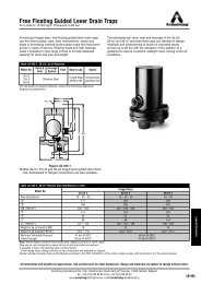
Humidification Selection Guide<br />
Humidification<br />
Eng<strong>in</strong>eer<strong>in</strong>g Guidel<strong>in</strong>es<br />
Table 4-1. Armstrong Humidification Selection Guide<br />
<strong>Central</strong> <strong>Steam</strong> Available<br />
Air Handl<strong>in</strong>g<br />
System Application<br />
with Critical<br />
Vapor Trail<br />
No Chemical<br />
Concern with<br />
Plant <strong>Steam</strong><br />
Concern with<br />
Chemicals<br />
<strong>Steam</strong><br />
From DI Source<br />
Hard Water<br />
Used. M<strong>in</strong>imal<br />
Ma<strong>in</strong>tenance.<br />
<strong>Central</strong> <strong>Steam</strong> Not Available<br />
Tap Water Used.<br />
Price More Critical<br />
Than Performance<br />
DI Water Used<br />
(Electrical Units)<br />
C D/I C E/I F/I E/I<br />
Air Handl<strong>in</strong>g<br />
System Application<br />
with Non-Critical<br />
Vapor Trail<br />
Direct Area<br />
Discharge<br />
A/G D/H/K B/G E/H F/H E/H<br />
A/J D/J B/J E/J F/J E/J<br />
Humidifier Type Key<br />
A. Series 9000 Direct <strong>Steam</strong> Injection Humidifier<br />
B. Series 1000 Direct <strong>Steam</strong> Injection Humidifier<br />
C. HumidiPack/HumidiPack Plus System with Control Valve,<br />
Trap and Stra<strong>in</strong>er<br />
D. Series CS-10 <strong>Steam</strong>-to-<strong>Steam</strong> Humidifier<br />
E. Series HC-4000 HumidiClean Electronic Humidifier<br />
F. Series EHU-700 Electrode Type Electronic Humidifier<br />
Dispersion Type<br />
G. SS Jacketed Manifold<br />
H. SS Non-Jacketed Dispersion Tube<br />
I. HumidiPack Distribution Panel (Only)<br />
J. Fan Type Dispersion<br />
K. <strong>Steam</strong> Jacketed Dispersion Tube (SJDT)<br />
Critical Vapor Trail <strong>in</strong>cludes requirements < 90 cm<br />
4<br />
Armstrong International SA • Parc Industriel des Hauts-Sarts (2 e Avenue) • 4040 Herstal • Belgium<br />
Tel.: +32 (0)4 240 90 90 • Fax: +32 (0)4 248 13 61<br />
www.armstrong.be • market<strong>in</strong>g@armstrong.be
Humidification Plays an Essential Role<br />
Although humidity is <strong>in</strong>visible to our eyes, we can easily<br />
observe its effects. In human terms, we are more comfortable<br />
and more efficient with proper humidification. In bus<strong>in</strong>ess and<br />
<strong>in</strong>dustrial environments, the performance of equipment and<br />
materials is enhanced by effectively apply<strong>in</strong>g humidity control.<br />
Ma<strong>in</strong>ta<strong>in</strong><strong>in</strong>g <strong>in</strong>door air quality through humidity management<br />
can lower energy costs, <strong>in</strong>crease productivity, save labor and<br />
ma<strong>in</strong>tenance costs, and ensure product quality. In short,<br />
humidification can provide a better environment and improve<br />
the quality of life and work.<br />
Inside the Humidification Eng<strong>in</strong>eer<strong>in</strong>g Section…<br />
Why Humidification is Important<br />
How Humidity Affects Materials<br />
Determ<strong>in</strong><strong>in</strong>g Humidity Requirements of Materials<br />
How Psychrometrics Help <strong>in</strong> Humidification<br />
How <strong>Humidifiers</strong> Work<br />
Humidification<br />
Eng<strong>in</strong>eer<strong>in</strong>g Guidel<strong>in</strong>es<br />
Armstrong has been shar<strong>in</strong>g know-how <strong>in</strong> humidification<br />
application s<strong>in</strong>ce 1938. Through the design, manufactur<strong>in</strong>g, and<br />
application of humidification equipment Armstrong has led the<br />
way to countless sav<strong>in</strong>gs <strong>in</strong> energy, time and money. Armstrong<br />
also provides humidification siz<strong>in</strong>g and selection software,<br />
videotapes, and other educational materials to aid <strong>in</strong><br />
humidification equipment selection, siz<strong>in</strong>g, <strong>in</strong>stallation, and<br />
ma<strong>in</strong>tenance.<br />
Armstrong offers this updated Humidification Eng<strong>in</strong>eer<strong>in</strong>g<br />
section as a problem-solv<strong>in</strong>g, educational aid for those <strong>in</strong>volved<br />
with the design, <strong>in</strong>stallation, and ma<strong>in</strong>tenance of environmental<br />
control systems <strong>in</strong> all types of build<strong>in</strong>gs. In addition, you may<br />
request a free copy of Armstrong’s Humid-A-ware<br />
Humidification Siz<strong>in</strong>g and Selection Software for step-by-step<br />
siz<strong>in</strong>g of your own <strong>in</strong>stallation. It can also be ordered by<br />
access<strong>in</strong>g www.armstrong.be.<br />
Your specific humidification questions can be answered by your<br />
Armstrong Representative. Additional support from Armstrong<br />
International humidification specialists is available to assist with<br />
difficult or unusual applications.<br />
Controlled humidification helps protect humidity-sensitive<br />
materials, personnel, delicate mach<strong>in</strong>ery, and equipment.<br />
Beyond the important issues of comfort and process control,<br />
humidity control can help safeguard aga<strong>in</strong>st explosive<br />
atmospheres. You can’t afford NOT to humidify. And the best<br />
way to protect your <strong>in</strong>vestment is through proven humidification<br />
strategies and solutions pioneered by Armstrong.<br />
Considerations <strong>in</strong> Select<strong>in</strong>g <strong>Steam</strong> <strong>Humidifiers</strong><br />
Basic Application Pr<strong>in</strong>ciples of <strong>Steam</strong> <strong>Humidifiers</strong><br />
Siz<strong>in</strong>g Considerations of <strong>Steam</strong> <strong>Humidifiers</strong><br />
<strong>Steam</strong> <strong>Humidifiers</strong> <strong>in</strong> <strong>Central</strong> <strong>Systems</strong><br />
Installation Tips<br />
Application of Unit <strong>Humidifiers</strong> for Direct Discharge<br />
References<br />
ASHRAE Handbook, 2000 <strong>Systems</strong> and Equipment.<br />
ASHRAE Handbook, 2002 Fundamentals.<br />
ASHRAE Handbook, 1999 HVAC Applications.<br />
IBM Installation Plann<strong>in</strong>g Manual, April, 1973.<br />
Obert, Edward F. Thermodynamics, 1948.<br />
Static Electricity, National Fire Protection Association. 1941.<br />
U.S. National Bureau of Standards.<br />
IMPORTANT: This section is <strong>in</strong>tended to summarize<br />
general pr<strong>in</strong>ciples of <strong>in</strong>stallation and operation. Actual<br />
<strong>in</strong>stallation and operation should be performed only by<br />
experienced personnel. Selection or <strong>in</strong>stallation should<br />
always be accompanied by competent technical<br />
assistance or advice. This data should never be used as a<br />
substitute for such technical advice or assistance. We<br />
encourage you to contact Armstrong or its local<br />
Representative for further details.<br />
Armstrong International SA • Parc Industriel des Hauts-Sarts (2 e Avenue) • 4040 Herstal • Belgium<br />
Tel.: +32 (0)4 240 90 90 • Fax: +32 (0)4 248 13 61<br />
www.armstrong.be • market<strong>in</strong>g@armstrong.be<br />
5
Why Humidification is Important<br />
Humidification<br />
Eng<strong>in</strong>eer<strong>in</strong>g Guidel<strong>in</strong>es<br />
Relative Humidity (RH):<br />
The ratio of the vapor pressure (or mole fraction) of water<br />
vapor <strong>in</strong> the air to the vapor pressure (or mole fraction) of<br />
saturated air at the same dry-bulb temperature and<br />
pressure.<br />
Sensible Heat:<br />
Heat that when added to or taken away from a substance<br />
causes a change <strong>in</strong> temperature or, <strong>in</strong> other words, is<br />
“sensed” by a thermometer. Measured <strong>in</strong> kJ.<br />
Latent Heat:<br />
Heat that when added to or taken away from a substance<br />
causes or accompanies a phase change for that<br />
substance. This heat does not register on a thermometer,<br />
hence its name “latent” or hidden. Measured <strong>in</strong> kJ.<br />
Dew Po<strong>in</strong>t:<br />
The temperature at which condensation occurs (100%RH)<br />
when air is cooled at a constant pressure without add<strong>in</strong>g<br />
or tak<strong>in</strong>g away water vapor.<br />
Evaporative Cool<strong>in</strong>g:<br />
A process <strong>in</strong> which liquid water is evaporated <strong>in</strong>to air. The<br />
liquid absorbs the heat necessary for the evaporation<br />
process from the air, thus, there is a reduction <strong>in</strong> air<br />
temperature and an <strong>in</strong>crease <strong>in</strong> the actual water vapor<br />
content of the air.<br />
Enthalpy:<br />
Also called heat content, this is the sum of the <strong>in</strong>ternal<br />
energy and the product of the volume times the<br />
pressure. Measured <strong>in</strong> kJ/kg.<br />
Hygroscopic Materials:<br />
Materials capable of absorb<strong>in</strong>g or giv<strong>in</strong>g up moisture.<br />
Humidity and Temperature<br />
Humidity is water vapor or moisture content always present <strong>in</strong><br />
the air. Humidity is def<strong>in</strong>able as an absolute measure: the<br />
amount of water vapor <strong>in</strong> a unit of air. But this measure of<br />
humidity does not <strong>in</strong>dicate how dry or damp the air is. This can<br />
only be done by comput<strong>in</strong>g the ratio of the actual partial vapor<br />
pressure to the saturated partial vapor pressure at the same<br />
temperature. This is relative humidity, expressed by the formula:<br />
vp a = actual vapor pressure<br />
vp s = vapor pressure at saturation<br />
t = dry-bulb temperature<br />
For practical purposes, at temperatures and pressures normally<br />
encountered <strong>in</strong> build<strong>in</strong>g systems, relative humidity is considered<br />
as the amount of water vapor <strong>in</strong> the air compared to the amount<br />
the air can hold at a given temperature.<br />
“At a given temperature” is the key to understand<strong>in</strong>g relative<br />
humidity. Warm air has the capacity to hold more moisture than<br />
cold air. For example, 1 cubic meter of 21°C air can hold 18,8 g<br />
of moisture. The same 1 cubic meter of air at 0°C can hold only<br />
4,9 g of moisture.<br />
21°C<br />
18,8 g/m³<br />
RH = vp a<br />
vp s<br />
t<br />
0°C<br />
4,9 g/m³<br />
Phase:<br />
The states of existence for a substance, solid, liquid, or<br />
gas (vapor).<br />
Humidification is simply the addition of water to air. However,<br />
humidity exerts a powerful <strong>in</strong>fluence on environmental and<br />
physiological factors. Improper humidity levels (either too high<br />
or too low) can cause discomfort for people, and can damage<br />
many k<strong>in</strong>ds of equipment and materials. Conversely, the proper<br />
type of humidification equipment and controls can help you<br />
achieve effective, economical, and trouble-free control of<br />
humidity.<br />
As we consider the importance of humidity among other<br />
environmental factors – temperature, cleanl<strong>in</strong>ess, air movement<br />
and thermal radiation – it is important to remember that<br />
humidity is perhaps the least evident to human perception. Most<br />
of us will recognize and react more quickly to temperature<br />
changes, odors or heavy dust <strong>in</strong> the air, drafts, or radiant heat.<br />
S<strong>in</strong>ce relative humidity <strong>in</strong>terrelates with these variables, it<br />
becomes a vital <strong>in</strong>gredient <strong>in</strong> total environmental control.<br />
If 1 cubic meter of 0°C air held 3,6 g of moisture, its relative<br />
humidity would be 75%. If your heat<strong>in</strong>g system raises the<br />
temperature of this air to 21°C with no moisture added, it will<br />
still conta<strong>in</strong> 3,6 g of moisture. However, at 21°C, 1 cubic meter<br />
of air can hold 18,8 g of moisture. So the 3,6 grams it actually<br />
holds give it a relative humidity of slightly more than 19%.<br />
That’s very dry... drier than the Sahara Desert!<br />
6<br />
Armstrong International SA • Parc Industriel des Hauts-Sarts (2 e Avenue) • 4040 Herstal • Belgium<br />
Tel.: +32 (0)4 240 90 90 • Fax: +32 (0)4 248 13 61<br />
www.armstrong.be • market<strong>in</strong>g@armstrong.be
Air Movement and Humidity<br />
Another variable, air movement <strong>in</strong> the form of <strong>in</strong>filtration and<br />
exfiltration from the build<strong>in</strong>g, <strong>in</strong>fluences the relationship<br />
between temperature and relative humidity. Typically, one to<br />
three times every hour (and many more times with forced air<br />
make-up or exhaust) cold outdoor air replaces your <strong>in</strong>door air.<br />
Your heat<strong>in</strong>g system heats this cold, moist outdoor air,<br />
produc<strong>in</strong>g warm, dry <strong>in</strong>door air.<br />
Evaporative Cool<strong>in</strong>g<br />
We have discussed the effects of chang<strong>in</strong>g temperature on<br />
relative humidity. Alter<strong>in</strong>g RH can also cause temperature to<br />
change. For every kilogram of moisture evaporated by the air,<br />
the heat of vaporization reduces the sensible heat <strong>in</strong> the air by<br />
about 2 320 kJ. This can be moisture absorbed from people or<br />
from wood, paper, textiles, and other hygroscopic material <strong>in</strong><br />
the build<strong>in</strong>g. Conversely, if hygroscopic materials absorb<br />
moisture from humid air, the heat of vaporization can be<br />
released to the air, rais<strong>in</strong>g the sensible heat.<br />
Dew Po<strong>in</strong>t<br />
Condensation will form on w<strong>in</strong>dows whenever the temperature<br />
of the glass surface is below the dew po<strong>in</strong>t of the air. Table 7-2,<br />
from data presented <strong>in</strong> the ASHRAE <strong>Systems</strong> and Equipment<br />
Handbook, <strong>in</strong>dicates comb<strong>in</strong>ations of <strong>in</strong>door relative humidity<br />
and outside temperature at which condensation will form.<br />
Induction units, commonly used below w<strong>in</strong>dows <strong>in</strong> modern<br />
build<strong>in</strong>gs to blow heated air across the glass, permit carry<strong>in</strong>g<br />
higher relative humidities without visible condensation.<br />
Humidification<br />
Eng<strong>in</strong>eer<strong>in</strong>g Guidel<strong>in</strong>es<br />
Table 7-1. Kg of Water per Cubic Meter of Saturated Air and kg of Dry Air<br />
at Various Temperatures. (Abstracted from ASHRAE Handbook)<br />
Humidity Specific<br />
°C<br />
Ratio kg w /kg a Volume m³/kg °C Humidity : by Specific<br />
Ratio kg w /kg a Volume m³/kg<br />
-10<br />
-9<br />
-8<br />
-7<br />
-6<br />
-5<br />
-4<br />
-3<br />
-2<br />
-1<br />
0<br />
1<br />
2<br />
3<br />
4<br />
5<br />
6<br />
7<br />
0,0013425<br />
0,0014690<br />
0,0016062<br />
0,0017551<br />
0,0019166<br />
0,0024862<br />
0,0027081<br />
0,0029480<br />
0,0032074<br />
0,0034874<br />
0,003789<br />
0,004076<br />
0,004381<br />
0,004707<br />
0,005054<br />
0,005424<br />
0,005818<br />
0,006237<br />
0,7469<br />
0,7499<br />
0,7530<br />
0,7560<br />
0,7591<br />
0,7622<br />
0,7653<br />
0,7685<br />
0,7717<br />
0,7749<br />
0,7781<br />
0,7813<br />
0,7845<br />
0,7878<br />
0,7911<br />
0,7944<br />
0,7978<br />
0,8012<br />
8<br />
9<br />
10<br />
11<br />
12<br />
13<br />
14<br />
15<br />
16<br />
17<br />
18<br />
19<br />
20<br />
21<br />
22<br />
23<br />
24<br />
25<br />
0,006683<br />
0,007157<br />
0,007661<br />
0,008197<br />
0,008766<br />
0,009370<br />
0,010012<br />
0,010692<br />
0,011413<br />
0,012178<br />
0,012989<br />
0,013848<br />
0,014758<br />
0,015721<br />
0,016741<br />
0,017821<br />
0,018963<br />
0,020170<br />
0,8046<br />
0,8081<br />
0,8116<br />
0,8152<br />
0,8188<br />
0,8225<br />
0,8262<br />
0,8300<br />
0,8338<br />
0,8377<br />
0,8417<br />
0,8457<br />
0,8498<br />
0,8540<br />
0,8583<br />
0,8627<br />
0,8671<br />
0,8717<br />
Table 7-2. Relative Humidities at which Condensation will appear on<br />
W<strong>in</strong>dows at 21°C when Glass Surface is unheated<br />
Double Glass<br />
Outdoor Temperature S<strong>in</strong>gle Glass (Storm W<strong>in</strong>dows or<br />
Thermal Glass)<br />
-23°C<br />
-18°C<br />
-12°C<br />
-7°C<br />
-1°C<br />
4°C<br />
11%<br />
16%<br />
21%<br />
28%<br />
37%<br />
48%<br />
38%<br />
42%<br />
49%<br />
56%<br />
63%<br />
71%<br />
Armstrong International SA • Parc Industriel des Hauts-Sarts (2 e Avenue) • 4040 Herstal • Belgium<br />
Tel.: +32 (0)4 240 90 90 • Fax: +32 (0)4 248 13 61<br />
www.armstrong.be • market<strong>in</strong>g@armstrong.be<br />
7
Why Humidification is Important, cont<strong>in</strong>ued…<br />
Humidification<br />
Eng<strong>in</strong>eer<strong>in</strong>g Guidel<strong>in</strong>es<br />
Energy Conservation With Controlled RH<br />
Indoor relative humidity as we have computed it is called<br />
Theoretical Indoor Relative Humidity (TIRH). It virtually never<br />
exists. RH observed on a measur<strong>in</strong>g device known as a<br />
hygrometer will almost always exceed the TIRH. Why? Dry air<br />
is thirsty air. It seeks to draw moisture from any source it can.<br />
Thus it will soak up moisture from any hygroscopic materials<br />
(such as wood, paper, foodstuffs, leather, etc.) and dry out the<br />
nasal passages and sk<strong>in</strong> of human be<strong>in</strong>gs <strong>in</strong> the build<strong>in</strong>g.<br />
But is this free “humidification”? No, it is the most expensive<br />
k<strong>in</strong>d there is when translated <strong>in</strong>to terms of human comfort,<br />
material deterioration, and production difficulties. Moreover, it<br />
requires the same amount of energy whether the moisture is<br />
absorbed from people and materials or added to the air by an<br />
efficient humidification system.<br />
The true energy required for a humidification system is<br />
calculated from what the actual humidity level will be <strong>in</strong> the<br />
build<strong>in</strong>g, NOT from the theoretical level. In virtually all cases,<br />
the cost of controll<strong>in</strong>g RH at the desired level will be nom<strong>in</strong>al <strong>in</strong><br />
terms of additional energy load, and <strong>in</strong> some cases may result<br />
<strong>in</strong> reduced energy consumption.<br />
A major convention center <strong>in</strong> the <strong>Central</strong> United States reported<br />
that it experienced a decrease <strong>in</strong> overall steam consumption<br />
when it added steam humidification. From one heat<strong>in</strong>g season<br />
with no humidification to the next with humidifiers operat<strong>in</strong>g, the<br />
steam consumption for humidification was 820 tons, while the<br />
steam for heat<strong>in</strong>g decreased by 1 130 tons <strong>in</strong> the same period.<br />
The decreased (metered) consumption occurred despite 7.2%<br />
colder weather from the previous year. The records from this<br />
<strong>in</strong>stallation <strong>in</strong>dicate that it is possible to reduce the total amount<br />
of steam required for environmental control by ma<strong>in</strong>ta<strong>in</strong><strong>in</strong>g a<br />
higher, controlled relative humidity.<br />
Let’s exam<strong>in</strong>e a theoretical system us<strong>in</strong>g enthalpy (heat<br />
content) as our base.<br />
■ Assume a w<strong>in</strong>ter day with outside temperature of 0°C at<br />
75% RH.<br />
■ The enthalpy of the air is 7,1 kJ/kg dry air (DA).<br />
■ If the air is heated to 22°C without add<strong>in</strong>g moisture, the<br />
enthalpy becomes 29,2 kJ/kg DA.<br />
■ Theoretical relative humidity becomes 17%, but actual RH<br />
will be about 25%.<br />
■ At 22°C and 25% RH the enthalpy is 32,4 kJ/kg DA.<br />
■ The additional moisture is derived from hygroscopic<br />
materials and people <strong>in</strong> the area.<br />
But what about the additional energy – the difference between<br />
the 29,2 kJ/kg DA and 32,4 kJ/kg DA? This 11% <strong>in</strong>crease must<br />
come from the heat<strong>in</strong>g system to compensate for the<br />
evaporative cool<strong>in</strong>g effect. If a humidification system is used<br />
and moisture added to achieve a comfortable 35% RH, the<br />
enthalpy is 36,8 kJ/kg DA.<br />
This is only a 13,5% <strong>in</strong>crease over the “<strong>in</strong>evitable” energy load<br />
of 32,4 kJ/kg DA – substantially less than the theoretical<br />
<strong>in</strong>crease of 26% from 17% RH (29,2 kJ/kg DA) to 35% RH<br />
(36,8 kJ/kg DA) at 22°C. If the temperature was only 19°C at<br />
35% RH (because people can be comfortable at a lower<br />
temperature with higher humidity levels), the enthalpy is 32<br />
kJ/kg DA, or a slight decrease <strong>in</strong> energy.<br />
Problems With Dry Air<br />
Dry air can cause a variety of costly, troublesome, and<br />
sometimes dangerous problems. If you are not familiar with the<br />
effects of dry air, the cause of these problems may not be<br />
obvious. You should be concerned if you are process<strong>in</strong>g or<br />
handl<strong>in</strong>g hygroscopic materials such as wood, paper, textile<br />
fibers, leather, or chemicals. Dry air and/or fluctuat<strong>in</strong>g humidity<br />
can cause serious production problems and/or material<br />
deterioration.<br />
Static electricity can accumulate <strong>in</strong> dry atmospheric conditions<br />
and <strong>in</strong>terfere with efficient operation of production mach<strong>in</strong>ery or<br />
electronic office mach<strong>in</strong>es. Where static-prone materials such<br />
as paper, films, computer disks, and other plastics are handled,<br />
dry air <strong>in</strong>tensely aggravates the static problem. In potentially<br />
explosive atmospheres, dry air and its resultant static electricity<br />
accumulations can be extremely dangerous.<br />
INDOOR<br />
OUTDOOR<br />
8<br />
Armstrong International SA • Parc Industriel des Hauts-Sarts (2 e Avenue) • 4040 Herstal • Belgium<br />
Tel.: +32 (0)4 240 90 90 • Fax: +32 (0)4 248 13 61<br />
www.armstrong.be • market<strong>in</strong>g@armstrong.be
Humidity and Human Comfort<br />
Studies <strong>in</strong>dicate people are generally most comfortable when<br />
relative humidity is ma<strong>in</strong>ta<strong>in</strong>ed between 35% and 55%. When<br />
air is dry, moisture evaporates more readily from the sk<strong>in</strong>,<br />
produc<strong>in</strong>g a feel<strong>in</strong>g of chill<strong>in</strong>ess even with temperatures of 24°C<br />
or more. Because human perception of RH is often sensed as<br />
temperature differential, it’s possible to achieve comfortable<br />
conditions with proper humidity control at lower temperatures.<br />
The sav<strong>in</strong>gs <strong>in</strong> heat<strong>in</strong>g costs are typically very significant over<br />
the course of just a s<strong>in</strong>gle heat<strong>in</strong>g season.<br />
The Need for Humidity Control <strong>in</strong> Today’s Electronic<br />
Workplace<br />
Electronics are revolutioniz<strong>in</strong>g the way your office and plant<br />
floor operates, communicates, collects data, and ma<strong>in</strong>ta<strong>in</strong>s<br />
equipment. In the office, xerographic copies, phone systems,<br />
computers, and fax mach<strong>in</strong>es, even wall thermostats are<br />
electronically controlled. What’s more, office decor has far more<br />
work stations <strong>in</strong>corporat<strong>in</strong>g wall panels and furniture with<br />
natural and synthetic fabric than ever before.<br />
In manufactur<strong>in</strong>g areas, more mach<strong>in</strong>es are electronically<br />
controlled. In fact, you see more control rooms (just to house<br />
electronic control systems) than <strong>in</strong> previous years.<br />
All this means that the nature of today’s bus<strong>in</strong>ess makes proper<br />
humidification a virtual necessity.<br />
Why Improper Humidification Threatens Sensitive<br />
Electronic Equipment<br />
<strong>Central</strong> to all electronic circuits today is the IC (<strong>in</strong>tegrated<br />
circuit) or “chip”. The heart of the IC is a wafer-th<strong>in</strong> m<strong>in</strong>iature<br />
circuit engraved <strong>in</strong> semiconductor material. Electronic<br />
components – and chips <strong>in</strong> particular – can be overstressed by<br />
electrical transients (voltage spikes). This may cause crater<strong>in</strong>g<br />
and melt<strong>in</strong>g of m<strong>in</strong>ute areas of the semiconductor, lead<strong>in</strong>g to<br />
operational upsets, loss of memory, or permanent failure. The<br />
damage may be immediate or the component may fail sooner<br />
than an identical part not exposed to an electrical transient.<br />
A major cause of voltage spikes is electrostatic discharge<br />
(ESD). Although of extremely short duration, transients can be<br />
lethal to the wafer-th<strong>in</strong> surfaces of semiconductors. ESD may<br />
deliver voltage as high as lightn<strong>in</strong>g and it strikes faster. ESD is<br />
a particularly dangerous phenomenon because you are the<br />
source of these transients. It is the static electricity that builds<br />
up on your body. The jolt you get from touch<strong>in</strong>g a doorknob or<br />
shak<strong>in</strong>g someone’s hand is ESD. Table 9-1 below shows<br />
voltages which can be generated by everyday activities.<br />
Voltage accumulates on surfaces (<strong>in</strong> this case, the human<br />
body), and when the surface approaches another at a lower<br />
voltage a discharge of electrical voltage occurs. Note the<br />
humidity levels at which these voltages may be generated. As<br />
the level of humidity rises, voltages are reduced because a film<br />
of moisture forms on surfaces, conduct<strong>in</strong>g the charges to the<br />
ground. Although the 65%-90% RH cited <strong>in</strong> Table 9-1 is<br />
impractical for office areas, any <strong>in</strong>crease <strong>in</strong> humidity will yield a<br />
significant reduction <strong>in</strong> ESD events.<br />
ESD Damage is Not Only Possible but Probable<br />
A study of personnel ESD events <strong>in</strong> a poorly controlled room<br />
with a wool carpet was conducted for 16 months. The strength<br />
of the ESD event was measured <strong>in</strong> current (amps). Results<br />
<strong>in</strong>dicate, for example, that a current discharge of 0,3 amps is<br />
100 times more likely to occur at 10%-20% RH than at 45%-<br />
50% RH. In other words, the higher the relative humidity, the<br />
lower the occurrence and severity of ESD.<br />
In addition to the risk of damage to electronic devices from<br />
static electricity charges, there are grave risks associated with<br />
sparks from static charges <strong>in</strong> many process applications. Static<br />
electricity is extremely dangerous <strong>in</strong> the presence of gases,<br />
volatile liquids, or explosive dusts such as is found <strong>in</strong> munitions<br />
plants, pa<strong>in</strong>t spray booths, pr<strong>in</strong>t<strong>in</strong>g plants, pharmaceutical<br />
plants, and other places.<br />
While many static control products (special mats, carpet<strong>in</strong>g,<br />
sprays, straps, etc.) are available, bear <strong>in</strong> m<strong>in</strong>d that<br />
humidification is a passive static-control means. It is work<strong>in</strong>g to<br />
control static all the time – not just when someone remembers.<br />
Humidification<br />
Eng<strong>in</strong>eer<strong>in</strong>g Guidel<strong>in</strong>es<br />
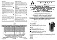
Figure 9-1. Effect of humidity on electrostatic voltages.<br />
Table 9-1. Effect of Humidity on Electrostatic Voltages<br />
Electrostatic Voltages<br />
Means of Static Generation 10%-20%<br />
Relative Humidity<br />
65%-90%<br />
Relative Humidity<br />
Walk<strong>in</strong>g across carpet<br />
Walk<strong>in</strong>g over v<strong>in</strong>yl floor<br />
Worker at bench<br />
V<strong>in</strong>yl envelopes for work <strong>in</strong>structions<br />
Common poly bag picked up from bench<br />
Work chair padded with polyurethane foam<br />
35 000<br />
12 000<br />
6 000<br />
7 000<br />
20 000<br />
18 000<br />
1 500<br />
250<br />
100<br />
600<br />
1 200<br />
1 500<br />
Integrated circuit damaged by ESD.<br />
(Photo courtesy of Motorola Semiconductor, Inc.)<br />
Armstrong International SA • Parc Industriel des Hauts-Sarts (2 e Avenue) • 4040 Herstal • Belgium<br />
Tel.: +32 (0)4 240 90 90 • Fax: +32 (0)4 248 13 61<br />
www.armstrong.be • market<strong>in</strong>g@armstrong.be<br />
9
How Humidity Affects Materials<br />
Humidification<br />
Eng<strong>in</strong>eer<strong>in</strong>g Guidel<strong>in</strong>es<br />
Paper and Paper Products<br />
Every production super<strong>in</strong>tendent <strong>in</strong> the paper <strong>in</strong>dustry is, by<br />
experience, familiar with the excessive scrap losses and<br />
customer compla<strong>in</strong>ts that can result from the follow<strong>in</strong>g<br />
w<strong>in</strong>tertime headaches:<br />
1. Curl<strong>in</strong>g of stock.<br />
2. Crack<strong>in</strong>g or break<strong>in</strong>g at creases of fold<strong>in</strong>g boxes, cartons,<br />
corrugated and solid fiber conta<strong>in</strong>ers.<br />
3. Loss of package and conta<strong>in</strong>er strength.<br />
4. Production delays when sheets fail to go through mach<strong>in</strong>es<br />
smoothly due to static electricity.<br />
5. Glu<strong>in</strong>g failures.<br />
All of the above w<strong>in</strong>tertime problems have a common cause –<br />
dry or curl<strong>in</strong>g paper caused by low <strong>in</strong>door relative humidities.<br />
The RH of surround<strong>in</strong>g air governs the moisture content of<br />
paper, as shown <strong>in</strong> Table 11-1. The fibrils <strong>in</strong> paper take on<br />
moisture when the paper is drier than the surround<strong>in</strong>g air and<br />
give up moisture when the conditions are reversed.<br />
A paper moisture content range of 5%-7% is essential to<br />
ma<strong>in</strong>ta<strong>in</strong> satisfactory strength and workability of paper. This<br />
requires an <strong>in</strong>door RH of about 40%-50%, depend<strong>in</strong>g upon the<br />
composition of the paper.<br />
Moisture contents of different types of papers will vary slightly<br />
from those shown <strong>in</strong> the table but will follow an identical pattern.<br />
Changes <strong>in</strong> moisture content thus cause paper to become<br />
thicker or th<strong>in</strong>ner, flatter or curlier, harder or softer, larger or<br />
smaller, limp or brittle.<br />
Whenever you heat air, without add<strong>in</strong>g moisture, its RH drops.<br />
Table 10-1 shows that -18°C outside air at 75% RH will have a<br />
relative humidity of only 4.4% when heated to 21°C <strong>in</strong>doors.<br />
Even though the theoretical RH should be 4.4% <strong>in</strong> your plant,<br />
the actual observed humidity will be much higher because of<br />
the moisture given off by the paper. This type of humidification<br />
is very expensive <strong>in</strong> terms of stock and production.<br />
Table 10-1. How Indoor Heat<strong>in</strong>g Reduces Indoor RH and Dries Out Paper<br />
Outdoor<br />
Indoor Temperature 21°C<br />
Temperature<br />
<strong>in</strong> °C<br />
Indoor Relative<br />
Humidity %<br />
Approximate Moisture<br />
Content of Paper %<br />
-29<br />
-23<br />
-18<br />
-12<br />
-7<br />
-1<br />
4<br />
10<br />
16<br />
21<br />
1,5<br />
2,5<br />
4,4<br />
7,2<br />
11,6<br />
18,1<br />
26,8<br />
38,3<br />
54,0<br />
75,0<br />
0,5<br />
0,8<br />
1,2<br />
2,2<br />
3,3<br />
4,3<br />
5,3<br />
6,4<br />
8,0<br />
11,6<br />
Figure 10-1.<br />
Effects of moisture content <strong>in</strong> fold<strong>in</strong>g paper. Sheet on left has<br />
proper moisture. Sheet on right lacks enough moisture – is dry<br />
and brittle – breaks on fold.<br />
Effect of Indoor Heat<strong>in</strong>g Upon RH and Moisture Content of<br />
Kraft Wrapp<strong>in</strong>g Paper. NOTE: This table assumes an outdoor<br />
relative humidity of 75%. When outdoor RH is less, as is<br />
common, <strong>in</strong>door RH will also be less. Indoor temperatures<br />
higher than 21°C will also cause lower relative humidities.<br />
10<br />
Armstrong International SA • Parc Industriel des Hauts-Sarts (2 e Avenue) • 4040 Herstal • Belgium<br />
Tel.: +32 (0)4 240 90 90 • Fax: +32 (0)4 248 13 61<br />
www.armstrong.be • market<strong>in</strong>g@armstrong.be
Pr<strong>in</strong>t<strong>in</strong>g<br />
The dry air problems found <strong>in</strong> paper manufactur<strong>in</strong>g are equally<br />
common to the pr<strong>in</strong>t<strong>in</strong>g <strong>in</strong>dustry.<br />
Leather Process<strong>in</strong>g<br />
RH ma<strong>in</strong>ta<strong>in</strong>ed uniformly <strong>in</strong> the 40%-60% range (higher <strong>in</strong><br />
muller rooms) reduces crack<strong>in</strong>g, m<strong>in</strong>imizes loss of pliability,<br />
helps ma<strong>in</strong>ta<strong>in</strong> quality and appearance, and reduces the dust<br />
problem <strong>in</strong> the plant.<br />
Offices<br />
RH ma<strong>in</strong>ta<strong>in</strong>ed at 30%-40% stops splitt<strong>in</strong>g, check<strong>in</strong>g, shr<strong>in</strong>kage,<br />
and glue jo<strong>in</strong>t failure <strong>in</strong> panel<strong>in</strong>g and furnish<strong>in</strong>gs, adds life to<br />
carpet<strong>in</strong>g and draperies. Electronic office equipment such as<br />
computers, xerographic copiers, and phone systems require a<br />
constant RH of 40%-50% to guard aga<strong>in</strong>st harmful electrical<br />
transients (see Page 9)<br />
Humidification<br />
Eng<strong>in</strong>eer<strong>in</strong>g Guidel<strong>in</strong>es<br />
Paper curl<strong>in</strong>g, generally caused by the expansion and<br />
contraction of an unprotected sheet of paper, takes place when<br />
too dry an atmosphere draws moisture from the exposed<br />
surface which shr<strong>in</strong>ks and curls. The curl will be with the gra<strong>in</strong><br />
of the sheet. This trouble is most pronounced with very<br />
lightweight stocks or with cover stocks and coated-one-side<br />
papers.<br />
Wood Products, Woodwork<strong>in</strong>g, and Furniture Manufacture<br />
Like all hygroscopic materials, wood takes on or gives off<br />
moisture as the RH of the surround<strong>in</strong>g air varies. When, at any<br />
given temperature and relative humidity, the wood f<strong>in</strong>ally stops<br />
absorb<strong>in</strong>g or liberat<strong>in</strong>g moisture, it is said to have reached its<br />
equilibrium moisture content (EMC). The moisture <strong>in</strong> the wood<br />
is then “<strong>in</strong> balance” with the moisture <strong>in</strong> the air.<br />
It is generally not practical to hold <strong>in</strong>door RH as high dur<strong>in</strong>g the<br />
cold months as it is dur<strong>in</strong>g the warm months. However, when<br />
the cold season sets <strong>in</strong>, humidifiers permit a gradual reduction<br />
of RH and EMC to a practical m<strong>in</strong>imum work<strong>in</strong>g level. Under<br />
this controlled condition, warp<strong>in</strong>g and crack<strong>in</strong>g will not occur.<br />
Libraries and Museums<br />
Relative humidity ma<strong>in</strong>ta<strong>in</strong>ed uniformly at 40%-55% <strong>in</strong> storage<br />
rooms, vaults, and galleries prolongs the life of valuable<br />
collections by stabiliz<strong>in</strong>g the pliability of glue, starch and case<strong>in</strong>.<br />
The embrittlement of fibers <strong>in</strong> paper, canvas, papyrus, leather<br />
b<strong>in</strong>d<strong>in</strong>gs, etc., is m<strong>in</strong>imized.<br />
Table 11-1. Moisture Content of Paper at Various Relative Humidities<br />
Relative Humidity %<br />
Material Description<br />
10 20 30 40 50 60 70 80 90<br />
M.F. Newspr<strong>in</strong>t<br />
HMF Writ<strong>in</strong>g<br />
White Bond<br />
Com. Ledger<br />
Kraft Wrapp<strong>in</strong>g<br />
Wood Pulp 24% Ash<br />
Wood Pulp 3% Ash<br />
Rag 1% Ash<br />
75% Rag 1% Ash<br />
Confireous<br />
2,1<br />
3,0<br />
2,4<br />
3,2<br />
3,2<br />
3,2<br />
4,2<br />
3,7<br />
4,2<br />
4,6<br />
4,0<br />
5,2<br />
4,7<br />
5,0<br />
5,7<br />
4,7<br />
6,2<br />
5,5<br />
5,6<br />
6,6<br />
5,3<br />
7,2<br />
6,5<br />
6,2<br />
7,6<br />
6,1<br />
8,3<br />
7,5<br />
6,9<br />
8,9<br />
7,2<br />
9,9<br />
8,8<br />
8,1<br />
10,5<br />
8,7<br />
11,9<br />
10,8<br />
10,3<br />
12,6<br />
10,6<br />
14,2<br />
13,2<br />
13,9<br />
14,9<br />
Armstrong International SA • Parc Industriel des Hauts-Sarts (2 e Avenue) • 4040 Herstal • Belgium<br />
Tel.: +32 (0)4 240 90 90 • Fax: +32 (0)4 248 13 61<br />
www.armstrong.be • market<strong>in</strong>g@armstrong.be<br />
11
Determ<strong>in</strong><strong>in</strong>g Humidity Requirements of Materials<br />
Humidification<br />
Eng<strong>in</strong>eer<strong>in</strong>g Guidel<strong>in</strong>es<br />
No s<strong>in</strong>gle level of relative humidity provides adequate moisture content <strong>in</strong> all hygroscopic materials. Moisture content requirements<br />
vary greatly from one material to the next. We will discuss typical hygroscopic materials which require specific RH levels to avoid<br />
moisture loss and materials deterioration and/or production problems that result.<br />
Table 12-1. Recommended Relative Humidities<br />
Process or Product Temp. °C %RH Process or Product Temp °C %RH Process or Product Temp. °C %RH<br />
Residences 21-22 30 Switchgear:<br />
Libraries & Museums<br />
Archival 13-18 35<br />
Art storage 16-22 50<br />
Stuffed fur animals 4-10 50<br />
Communication Centers<br />
Telephone term<strong>in</strong>als 22-26 40-50<br />
Radio & TV studios 23-26 30-40<br />
General Commercial & Public Build<strong>in</strong>gs<br />
21-23 20-30<br />
(<strong>in</strong>clud<strong>in</strong>g cafeterias, restaurants<br />
airport term<strong>in</strong>als, office build<strong>in</strong>gs & bowl<strong>in</strong>g centers)<br />
Hospitals & Health Facilities<br />
General cl<strong>in</strong>ical areas 22 30-60<br />
Surgical area<br />
Operat<strong>in</strong>g rooms 20-24 50-60<br />
Recovery rooms 24 50-60<br />
Obstetrical<br />
Full-term nursery 24 30-60<br />
Special care nursery 24-27 30-60<br />
Industrial Hygroscopic Materials<br />
Abrasive<br />
Manufacture 26 50<br />
Ceramics<br />
Refractory 43-66 50-90<br />
Mold<strong>in</strong>g Room 27 60-70<br />
Clay Storage 16-27 35-65<br />
Decalcomania production 24-27 48<br />
Decorat<strong>in</strong>g Room 24-27 48<br />
Cereal<br />
Packag<strong>in</strong>g 24-27 45-50<br />
Distill<strong>in</strong>g<br />
Storage<br />
Gra<strong>in</strong> -14 35-40<br />
Liquid Yeast 0-1<br />
General manufactur<strong>in</strong>g 16-24 45-60<br />
Ag<strong>in</strong>g 18-22 50-60<br />
Electrical Products<br />
Electronics & X-ray:<br />
Coil & transformer w<strong>in</strong>d<strong>in</strong>g 22 15<br />
Semi conductor assembly 20 40-50<br />
Electrical <strong>in</strong>struments:<br />
Manufacture & laboratory 21 50-55<br />
Thermostat assembly<br />
& calibration 24 50-55<br />
Humidistat assembly<br />
& calibration 24 50-55<br />
Small mechanisms:<br />
Close tolerance assembly 22 40-45<br />
Meter assembly & test 24 60-63<br />
Abstracted from ASHRAE <strong>Systems</strong> and Applications Handbook.<br />
Fuse & cutout assembly 23 50<br />
Capacitor w<strong>in</strong>d<strong>in</strong>g 23 50<br />
Paper Storage 23 50<br />
Conductor wrapp<strong>in</strong>g with yarn 24 65-70<br />
Lightn<strong>in</strong>g arrester assembly 20 20-40<br />
Thermal circuit breakers<br />
assembly & test 24 30-60<br />
High-voltage transformer repair 26 55<br />
Water wheel generators:<br />
Thrust runner lapp<strong>in</strong>g 21 30-50<br />
Rectifiers:<br />
Process<strong>in</strong>g selenium &<br />
copper oxide plates 23 30-40<br />
Fur<br />
Storage 4-10 55-65<br />
Gum<br />
Manufactur<strong>in</strong>g 25 33<br />
Roll<strong>in</strong>g 20 63<br />
Stripp<strong>in</strong>g 22 53<br />
Break<strong>in</strong>g 23 47<br />
Wrapp<strong>in</strong>g 23 58<br />
Leather<br />
Dry<strong>in</strong>g 20-52 75<br />
Storage, w<strong>in</strong>ter room temp. 10-16 40-60<br />
Lenses (Optical)<br />
Fus<strong>in</strong>g 24 45<br />
Gr<strong>in</strong>d<strong>in</strong>g 27 80<br />
Matches<br />
Manufacture 22-23 50<br />
Dry<strong>in</strong>g 21-24 60<br />
Storage 16-17 50<br />
Mushrooms<br />
Spawn added 16-22 **<br />
Grow<strong>in</strong>g period 10-16 80<br />
Storage 0-2 80-85<br />
Pa<strong>in</strong>t Application<br />
Oils, pa<strong>in</strong>ts: Pa<strong>in</strong>t Spray<strong>in</strong>g 16-32 80<br />
Plastics<br />
Manufactur<strong>in</strong>g areas:<br />
Thermosett<strong>in</strong>g mold<strong>in</strong>g<br />
compounds 27 25-30<br />
Cellophane wrapp<strong>in</strong>g 24-27 45-65<br />
Plywood<br />
Hot press<strong>in</strong>g (res<strong>in</strong>) 32 60<br />
Cold press<strong>in</strong>g 32 15-25<br />
Rubber-Dipped Goods<br />
Cement<strong>in</strong>g 27 25-30*<br />
Dipp<strong>in</strong>g surgical articles 24-27 25-30*<br />
Storage prior to manufacture 16-24 40-50*<br />
Laboratory (ASTM Standard) 23 50*<br />
* Dew po<strong>in</strong>t of air must be below evaporation temperature of solvent<br />
** Nearly saturated<br />
Tea<br />
Packag<strong>in</strong>g 18 65<br />
Tobacco<br />
Cigar & cigarette mak<strong>in</strong>g 21-24 55-65<br />
Soften<strong>in</strong>g 32 85-88<br />
Stemm<strong>in</strong>g & stripp<strong>in</strong>g 24-29 70-75<br />
Pack<strong>in</strong>g & shipp<strong>in</strong>g 23-24 65<br />
Filter tobacco cas<strong>in</strong>g<br />
& condition<strong>in</strong>g 24 75<br />
Filler tobacco storage<br />
& preparation 25 70<br />
Wrapper tobacco storage<br />
& condition<strong>in</strong>g 24 75<br />
Pharmaceuticals<br />
Powder storage (prior to mfg) * *<br />
Manufactured powder storage<br />
& pack<strong>in</strong>g areas 24 35<br />
Mill<strong>in</strong>g room 24 35<br />
Tablet compress<strong>in</strong>g 24 35<br />
Tablet coat<strong>in</strong>g room 24 35<br />
Effervescent tablets<br />
and powders 24 20<br />
Hypodermic tablets 24 30<br />
Colloids 24 30-50<br />
Cough drops 24 40<br />
Glandular products 24 5-10<br />
Ampoule manufactur<strong>in</strong>g 24 35-50<br />
Gelat<strong>in</strong> capsules 24 35<br />
Capsule Storage 24 35<br />
Microanalysis 24 50<br />
Biological manufactur<strong>in</strong>g 24 35<br />
Liver extracts 24 35<br />
Serums 24 50<br />
Animal rooms 24-27 50<br />
Small animal rooms 24-26 50<br />
* store <strong>in</strong> sealed plastic conta<strong>in</strong>ers <strong>in</strong> sealed drums.<br />
Photographic Process<strong>in</strong>g<br />
Photo studio<br />
Dress<strong>in</strong>g room 22-23 40-50<br />
Studio (camera room) 22-23 40-50<br />
Film darkroom 21-22 45-55<br />
Pr<strong>in</strong>t darkroom 21-22 45-55<br />
Dry<strong>in</strong>g room 32-38 35-45<br />
F<strong>in</strong>ish<strong>in</strong>g room 22-24 40-55<br />
Storage room<br />
b/w film & paper 22-24 40-60<br />
color film & paper 4-10 40-50<br />
Motion picture studio 22 40-55<br />
Static Electricity Control<br />
Textiles, paper, explosive control >55<br />
Clean Rooms & Spaces 45<br />
Data Process<strong>in</strong>g 22 45-50<br />
Paper Process<strong>in</strong>g<br />
F<strong>in</strong>ish<strong>in</strong>g area 21-24 40-45<br />
Test laboratory 23 50<br />
12<br />
Armstrong International SA • Parc Industriel des Hauts-Sarts (2 e Avenue) • 4040 Herstal • Belgium<br />
Tel.: +32 (0)4 240 90 90 • Fax: +32 (0)4 248 13 61<br />
www.armstrong.be • market<strong>in</strong>g@armstrong.be
8<br />
8<br />
8<br />
How Psychrometrics Help <strong>in</strong> Humidification<br />
Psychrometrics is the measurement of thermodynamic<br />
properties <strong>in</strong> moist air. As a problem-solv<strong>in</strong>g tool psychrometrics<br />
excel <strong>in</strong> clearly show<strong>in</strong>g how changes <strong>in</strong> heat<strong>in</strong>g, cool<strong>in</strong>g,<br />
humidification, and dehumidification can affect the properties of<br />
moist air. Psychrometric data is needed to solve various<br />
problems and processes relat<strong>in</strong>g to air distribution.<br />
Most complex problems relat<strong>in</strong>g to heat<strong>in</strong>g, cool<strong>in</strong>g and<br />
humidification are comb<strong>in</strong>ations of relatively simple problems.<br />
The psychrometric chart illustrates these processes <strong>in</strong> graphic<br />
form, clearly show<strong>in</strong>g how changes affect the properties of<br />
moist air.<br />
Humidification<br />
Eng<strong>in</strong>eer<strong>in</strong>g Guidel<strong>in</strong>es<br />
One of the reasons psychrometric data is particularly important<br />
today is traceable to the way most new build<strong>in</strong>gs (and many<br />
older ones) are heated. The lower duct temperatures (13°C and<br />
below) used <strong>in</strong> new build<strong>in</strong>gs make accurate humidity control<br />
more difficult to achieve. (This is because low duct<br />
temperatures have a limited ability to absorb moisture. Add<strong>in</strong>g<br />
moisture via the central air handl<strong>in</strong>g system must compensate<br />
for reheat<strong>in</strong>g of air before it leaves the duct.)<br />
For such applications, booster humidification must sometimes<br />
be accomplished <strong>in</strong> the duct of the zone after it has reached its<br />
f<strong>in</strong>al temperature (reheated).<br />
To ma<strong>in</strong>ta<strong>in</strong> typical conditions of 21°C and 50% RH, duct<br />
humidities will be very high (75% RH and above). To keep the<br />
duct from becom<strong>in</strong>g saturated, a duct high limit humidistat is<br />
used, and becomes <strong>in</strong> these cases the ma<strong>in</strong> controller of the<br />
humidifier. S<strong>in</strong>ce this humidistat is <strong>in</strong> close proximity to the<br />
humidifier, and air is constantly mov<strong>in</strong>g, and must be controlled<br />
close to saturation, the humidifier output control must be fast,<br />
accurate and repeatable.<br />
30<br />
1,0<br />
1,0<br />
10,0<br />
0,8<br />
0,7<br />
0,6<br />
0,5<br />
4,0<br />
1,5<br />
2,0<br />
-5,0<br />
-2,0<br />
100<br />
30<br />
28<br />
0,94<br />
5,0 0,4<br />
0,3<br />
4,0<br />
SENSIBHLE HEAT<br />
= ∆h<br />
TOTAL HEAT ∆W<br />
-0,5<br />
0,2<br />
-0,2<br />
0,1 0<br />
-1,0<br />
-4,0<br />
-2,0<br />
1,0<br />
0,0<br />
90<br />
30<br />
26<br />
24<br />
120<br />
3,0<br />
2,5<br />
ENTHALPY<br />
HUMIDITY RATIO =<br />
∆h<br />
∆W<br />
2,0<br />
70<br />
80<br />
25<br />
22<br />
20<br />
110<br />
0,92 m³ (Volume per kg Dry Air)<br />
30<br />
40<br />
50<br />
60<br />
20<br />
15<br />
Saturation Temperature <strong>in</strong> °C<br />
15<br />
90%<br />
20<br />
80%<br />
70%<br />
0,86<br />
60%<br />
50%<br />
40%<br />
25°C (Wet Bulb Temperature)<br />
0,88<br />
0,90<br />
18<br />
16<br />
14<br />
12<br />
10<br />
100<br />
90<br />
80<br />
20<br />
5<br />
10<br />
10<br />
0,84<br />
30%<br />
20%<br />
8<br />
6<br />
70<br />
0,82<br />
0<br />
5<br />
0,80<br />
10% (Relative Humidity)<br />
4<br />
60<br />
0,78<br />
2<br />
0 10 20<br />
30 40 50<br />
Armstrong International SA • Parc Industriel des Hauts-Sarts (2 e Avenue) • 4040 Herstal • Belgium<br />
Tel.: +32 (0)4 240 90 90 • Fax: +32 (0)4 248 13 61<br />
www.armstrong.be • market<strong>in</strong>g@armstrong.be<br />
13
8<br />
8<br />
8<br />
Us<strong>in</strong>g the Psychrometric Chart<br />
Humidification<br />
Eng<strong>in</strong>eer<strong>in</strong>g Guidel<strong>in</strong>es<br />
The psychrometric chart is a graphical representation of the<br />
thermodynamic properties which impact moist air.<br />
It consists of eight major components:<br />
0,030<br />
0,028<br />
0,026<br />
0,024<br />
0,022<br />
0,020<br />
70<br />
80<br />
90<br />
100<br />
120<br />
110<br />
100<br />
0,018<br />
60<br />
0,016<br />
50<br />
90<br />
0,014<br />
0,012<br />
40<br />
80<br />
0,010<br />
30<br />
0,008<br />
0,006<br />
0,004<br />
0,002<br />
0<br />
10<br />
20<br />
20 30<br />
0 10 40 50<br />
70<br />
60<br />
1. Humidity ratio values are plotted<br />
vertically along the right-hand marg<strong>in</strong>,<br />
beg<strong>in</strong>n<strong>in</strong>g with 0 kg/kg of dry air at the<br />
bottom and extend<strong>in</strong>g to 0,03 kg/kg of dry<br />
air at the top.<br />
2. Enthalpy, or total heat, is plotted with<br />
oblique l<strong>in</strong>es, at <strong>in</strong>tervals of 10 kJ/kg of<br />
dry air, extend<strong>in</strong>g from upper left to lower<br />
right.<br />
30<br />
15<br />
20<br />
25<br />
90%<br />
100%<br />
80%<br />
70%<br />
60%<br />
50%<br />
40%<br />
30%<br />
20%<br />
10<br />
10%<br />
0 5 10 15 20 25 30 35 40 45 50<br />
5<br />
3. Dry-bulb temperature l<strong>in</strong>es are plotted<br />
vertically at 1°C <strong>in</strong>tervals.<br />
4. Wet-bulb temperature l<strong>in</strong>es are<br />
<strong>in</strong>dicated obliquely and fall almost parallel<br />
to enthalpy l<strong>in</strong>es. They are shown at 1°C<br />
<strong>in</strong>tervals.<br />
5. Relative humidity l<strong>in</strong>es curve across<br />
the chart form left to right at <strong>in</strong>tervals of<br />
10%. They beg<strong>in</strong> at the bottom at 10%<br />
and end at the top with the saturation<br />
curve (100%).<br />
1,0<br />
1,0<br />
0,94<br />
0,86<br />
0,89<br />
0,90<br />
0,92<br />
Saturation Temperature <strong>in</strong> °C<br />
0,8<br />
10,0 0,7<br />
0,6<br />
0,5<br />
5,0 0,4<br />
0,3<br />
4,0<br />
SENSIBHLE HEAT<br />
= ∆h<br />
TOTAL HEAT ∆W<br />
-0,5<br />
0,2<br />
-0,2<br />
0,1 0<br />
3,0<br />
2,5<br />
2,0<br />
-1,0<br />
-4,0<br />
-2,0<br />
2,0<br />
4,0<br />
1,5<br />
1,0<br />
0,0<br />
-5,0<br />
-2,0<br />
0,84<br />
0,82<br />
0,78<br />
0,80<br />
ENTHALPY<br />
HUMIDITY RATIO =<br />
∆h<br />
∆W<br />
6. Volume l<strong>in</strong>es <strong>in</strong>dicat<strong>in</strong>g cubic meter<br />
per kilogram of dry air are plotted at<br />
<strong>in</strong>tervals of 0,01 m³.<br />
7. Two-phase region <strong>in</strong>cludes a narrow,<br />
cross-hatched area to the left of the<br />
saturation region <strong>in</strong>dicat<strong>in</strong>g a mixture of<br />
condensed water <strong>in</strong> equilibrium.<br />
8. The protractor at the upper left of the<br />
chart conta<strong>in</strong>s two scales. One is for the<br />
ration of enthalpy difference. The other is<br />
for a ratio of sensible heat to the total<br />
heat. The protractor establishes the angle<br />
of a l<strong>in</strong>e on the chart along which a<br />
process will follow.<br />
14<br />
Armstrong International SA • Parc Industriel des Hauts-Sarts (2 e Avenue) • 4040 Herstal • Belgium<br />
Tel.: +32 (0)4 240 90 90 • Fax: +32 (0)4 248 13 61<br />
www.armstrong.be • market<strong>in</strong>g@armstrong.be
Table 15-1. System 1<br />
100% outside air<br />
A Outside conditions<br />
B Preheat<br />
C Humidification with steam<br />
D Reheat (f<strong>in</strong>al)<br />
∆X (X2-X1)<br />
Dry Bulb t°<br />
<strong>in</strong> °C<br />
0<br />
13<br />
13<br />
22<br />
Wet Bulb t°<br />
<strong>in</strong> °C<br />
-1,2<br />
6,0<br />
12,0<br />
15,4<br />
Specif. Vol.<br />
<strong>in</strong> m³/kg<br />
0,778<br />
0,816<br />
0,821<br />
0,847<br />
Enthalpy<br />
<strong>in</strong> kJ/kg air<br />
7,5<br />
20,5<br />
34,0<br />
43,0<br />
RH<br />
<strong>in</strong> %<br />
80<br />
32<br />
89<br />
50<br />
Hum. Ratio<br />
<strong>in</strong> g/kg air<br />
3,0 (X1)<br />
3,0<br />
8,3<br />
8,3 (X2)<br />
5,3<br />
80<br />
90<br />
100<br />
30<br />
30<br />
28<br />
26<br />
24<br />
22<br />
Humidification<br />
Eng<strong>in</strong>eer<strong>in</strong>g Guidel<strong>in</strong>es<br />
70<br />
25<br />
20<br />
NC<br />
EA<br />
T<br />
100% OSA<br />
Supply<br />
A B Fan C D<br />
M<br />
Exhaust<br />
Fan<br />
Duct Controller<br />
Preheat<br />
H<br />
T<br />
EA Grille<br />
Motor<br />
Reheat<br />
90% RH High-Limit Duct<br />
Humidity Controller<br />
20<br />
30<br />
5<br />
40<br />
10<br />
50<br />
C<br />
10<br />
60<br />
20<br />
15<br />
Saturation Temperature <strong>in</strong> °C<br />
0,84<br />
D<br />
90%<br />
20<br />
80%<br />
15°C (Wet Bulb Temperature)<br />
70%<br />
60%<br />
50%<br />
40%<br />
30%<br />
0,88<br />
20%<br />
18<br />
16<br />
14<br />
12<br />
10<br />
8<br />
6<br />
Glossary of Symbols<br />
EA...............Exhaust Air<br />
E-P relay.... Electric-Pneumatic relay<br />
H.................Humidity controller<br />
M................Damper motor<br />
MA..............Mixed air<br />
NC............... Normally closed<br />
NO............... Normally open<br />
OSA............. Outside Air<br />
RA............... Return Air<br />
T.................. Temperature Controller<br />
A<br />
0,78<br />
0<br />
5<br />
0,80<br />
0,82<br />
B<br />
0,86 m³ (Volume per kg Dry Air)<br />
10% (Relative Humidity)<br />
4<br />
2<br />
0 10 20<br />
30<br />
Table 15-2. System 2<br />
Dry Bulb t°<br />
<strong>in</strong> °C<br />
Wet Bulb t°<br />
<strong>in</strong> °C<br />
Specif. Vol.<br />
<strong>in</strong> m³/kg<br />
Enthalpy<br />
<strong>in</strong> kJ/kg air<br />
RH<br />
<strong>in</strong> %<br />
Hum. Ratio<br />
<strong>in</strong> g/kg air<br />
30<br />
A<br />
B<br />
C<br />
D<br />
90% recirculated air<br />
Outside conditions<br />
Mix<strong>in</strong>g conditions<br />
Reheat<br />
Humidification<br />
∆X (X2-X1)<br />
0<br />
20<br />
22<br />
22<br />
-1,2<br />
14,3<br />
15,0<br />
15,4<br />
0,778<br />
0,841<br />
0,847<br />
0,847<br />
7,5<br />
40,0<br />
42,0<br />
43,0<br />
80<br />
54<br />
48<br />
50<br />
3,0<br />
7,7 (X1)<br />
7,7<br />
8,3 (X2)<br />
0,6<br />
80<br />
90<br />
100<br />
30<br />
28<br />
26<br />
24<br />
22<br />
T<br />
A B C<br />
100% OSA<br />
M<br />
Space Humidity Control<br />
Modulates Humidifier Valve<br />
to Ma<strong>in</strong>ta<strong>in</strong> Space RH<br />
RA<br />
NO<br />
NC<br />
E-P Relay Bleeds Air From<br />
Humidifier Diaphragm When<br />
Fan is Off<br />
T<br />
H<br />
Supply<br />
Fan<br />
Fan Switch Energizes<br />
Control System<br />
90% RH High-Limit Duct<br />
Humidity Controller<br />
D<br />
H<br />
300 - 360 cm<br />
M<strong>in</strong>.<br />
Humidifier With <strong>Steam</strong><br />
Jacketed Distribution Manifold<br />
Sized for Max. Design Load<br />
20<br />
30<br />
5<br />
40<br />
10<br />
50<br />
10<br />
60<br />
70<br />
20<br />
15<br />
Saturation Temperature <strong>in</strong> °C<br />
B<br />
0,84<br />
C<br />
D<br />
25<br />
90%<br />
20<br />
80%<br />
70%<br />
15°C (Wet Bulb Temperature)<br />
60%<br />
50%<br />
40%<br />
30%<br />
0,88<br />
20%<br />
20<br />
18<br />
16<br />
14<br />
12<br />
10<br />
8<br />
6<br />
Glossary of Symbols<br />
EA...............Exhaust Air<br />
E-P relay.... Electric-Pneumatic relay<br />
H.................Humidity controller<br />
M................Damper motor<br />
MA..............Mixed air<br />
NC............... Normally closed<br />
NO............... Normally open<br />
OSA............. Outside Air<br />
RA............... Return Air<br />
T.................. Temperature Controller<br />
A<br />
0,78<br />
0<br />
5<br />
0,80<br />
0,82<br />
0,86 m³ (Volume per kg Dry Air)<br />
10% (Relative Humidity)<br />
0 10 20<br />
30<br />
4<br />
2<br />
Armstrong International SA • Parc Industriel des Hauts-Sarts (2 e Avenue) • 4040 Herstal • Belgium<br />
Tel.: +32 (0)4 240 90 90 • Fax: +32 (0)4 248 13 61<br />
www.armstrong.be • market<strong>in</strong>g@armstrong.be<br />
15
How <strong>Humidifiers</strong> Work<br />
Humidification<br />
Eng<strong>in</strong>eer<strong>in</strong>g Guidel<strong>in</strong>es<br />
<strong>Steam</strong> Humidification (Isothermal)<br />
Unlike other humidification methods, steam humidifiers have a<br />
m<strong>in</strong>imal effect on dry-bulb (DB) temperatures. The steam<br />
humidifier discharges ready-made water vapor. This water<br />
vapor does not require any additional heat as it mixes with the<br />
air and <strong>in</strong>creases relative humidity. <strong>Steam</strong> is pure water vapor<br />
exist<strong>in</strong>g at 100°C. This high temperature creates a perception<br />
that steam, when discharged <strong>in</strong>to the air, will actually <strong>in</strong>crease<br />
air temperature. This is a common misconception. In truth, as<br />
the humidifier discharges steam <strong>in</strong>to the air, a steam/air mixture<br />
is established. In this mixture steam temperature will rapidly<br />
decrease to essentially the air temperature.<br />
50%<br />
30%<br />
Direct <strong>Steam</strong> Injection <strong>Humidifiers</strong><br />
The most common form of steam humidifier is the direct steam<br />
<strong>in</strong>jection type. From a ma<strong>in</strong>tenance po<strong>in</strong>t of view, direct steam<br />
humidification systems require very little upkeep. The steam<br />
supply itself acts as a clean<strong>in</strong>g agent to keep system<br />
components free of m<strong>in</strong>eral deposits that can clog many forms<br />
of water spray and evaporative pan systems.<br />
Response to control and p<strong>in</strong>po<strong>in</strong>t control of output are two other<br />
advantages of the direct steam humidification method. S<strong>in</strong>ce<br />
steam is ready-made water vapor, it needs only to be mixed<br />
with air to satisfy the demands of the system. In addition, direct<br />
steam humidifiers can meter output by means of a modulat<strong>in</strong>g<br />
control valve. As the system responds to control, it can position<br />
the valve anywhere from closed to fully open. As a result, direct<br />
steam humidifiers can respond more quickly and precisely to<br />
fluctuat<strong>in</strong>g demand.<br />
The high temperatures <strong>in</strong>herent <strong>in</strong> steam humidification make it<br />
virtually a sterile medium. Assum<strong>in</strong>g boiler makeup water is of<br />
satisfactory quality and there is no condensation, dripp<strong>in</strong>g or<br />
spitt<strong>in</strong>g <strong>in</strong> the ducts, no bacteria or odors will be dissem<strong>in</strong>ated<br />
with steam humidification.<br />
21°C DB<br />
The psychrometric chart helps illustrate that steam<br />
humidification is a constant DB process. Start<strong>in</strong>g from a po<strong>in</strong>t<br />
on any DB temperature l<strong>in</strong>e, steam humidification will cause<br />
movement straight up along the constant DB l<strong>in</strong>e. The example<br />
illustrates that 21°C DB is constant as we <strong>in</strong>crease RH from<br />
30% - 50%. This is true because steam conta<strong>in</strong>s the necessary<br />
heat (enthalpy) to add moisture without <strong>in</strong>creas<strong>in</strong>g or<br />
decreas<strong>in</strong>g DB temperature. Actual results utiliz<strong>in</strong>g high<br />
pressure steam or large RH <strong>in</strong>creases (more than 50%)<br />
<strong>in</strong>crease DB by 0,5° to 1°C. As a result, no additional heat<strong>in</strong>g or<br />
air condition<strong>in</strong>g load occurs.<br />
Corrosion is rarely a concern with a properly <strong>in</strong>stalled steam<br />
system. Scale and sediment – whether formed <strong>in</strong> the unit or<br />
entra<strong>in</strong>ed <strong>in</strong> the supply steam – are dra<strong>in</strong>ed from the humidifier<br />
through the steam trap.<br />
<strong>Steam</strong>-to-<strong>Steam</strong> <strong>Humidifiers</strong><br />
<strong>Steam</strong>-to-steam humidifiers use a heat exchanger and the heat<br />
of treated steam to create a secondary steam for humidification<br />
from untreated water. The secondary steam is typically at<br />
atmospheric pressure, plac<strong>in</strong>g <strong>in</strong>creased importance on<br />
equipment location.<br />
Ma<strong>in</strong>tenance of steam-to-steam humidifiers is dependent on<br />
water quality. Impurities such as calcium, magnesium and iron<br />
can deposit as scale, requir<strong>in</strong>g frequent clean<strong>in</strong>g. Response to<br />
control is slower than with direct steam because of the time<br />
required to boil the water.<br />
Direct <strong>Steam</strong> Humidification<br />
<strong>Steam</strong>-to-<strong>Steam</strong> Humidification<br />
Figure 16-1. Separator Type Figure 16-2. Panel Type Figure 16-3.<br />
AIR FLOW<br />
Cross Section of Manifold<br />
Conditioned <strong>Steam</strong><br />
Dra<strong>in</strong><br />
Dra<strong>in</strong><br />
16<br />
Armstrong International SA • Parc Industriel des Hauts-Sarts (2 e Avenue) • 4040 Herstal • Belgium<br />
Tel.: +32 (0)4 240 90 90 • Fax: +32 (0)4 248 13 61<br />
www.armstrong.be • market<strong>in</strong>g@armstrong.be
Electric <strong>Steam</strong> <strong>Humidifiers</strong> (Electrode)<br />
Electric steam humidifiers are used when a source of steam is<br />
not available. Electricity and water create steam at atmospheric<br />
pressure. Electrode-type units pass electrical current through<br />
water to provide proportional output. Use with pure<br />
dem<strong>in</strong>eralized, deionized or distilled water alone will generally<br />
not provide sufficient conductivity for electrode units.<br />
Water quality affects the operation and ma<strong>in</strong>tenance of<br />
electrode-type humidifiers. Use with hard water requires more<br />
frequent clean<strong>in</strong>g, and pure softened water can shorten<br />
electrode life. Microprocessor-based diagnostics assist with<br />
troubleshoot<strong>in</strong>g.<br />
Electrode units are easily adaptable to different control signals<br />
and offer full modulated output. However, the need to boil the<br />
water means control will not compare with direct-<strong>in</strong>jection units.<br />
Electric <strong>Steam</strong> <strong>Humidifiers</strong> (Resistance)<br />
This type of electric humidifiers typically use immersed<br />
resistance heat<strong>in</strong>g elements to boil water. S<strong>in</strong>ce current does<br />
not pass through water, conductivity is not a concern. Ionic bed<br />
technology makes the humidifier versatile enough to<br />
accommodate various water qualities. These units work by<br />
us<strong>in</strong>g ionic bed <strong>in</strong>serts conta<strong>in</strong><strong>in</strong>g fibrous media to attract solids<br />
from water as its temperature rises, m<strong>in</strong>imiz<strong>in</strong>g the buildup of<br />
solids <strong>in</strong>side the humidifier. Water quality does not affect<br />
operation, and ma<strong>in</strong>tenance typically consists of simply<br />
replac<strong>in</strong>g the <strong>in</strong>serts.<br />
Ionic bed humidifiers are adaptable to different control signals<br />
and offer full modulated output. Control is affected by the need<br />
to boil the water.<br />
Gas-Fired <strong>Steam</strong> <strong>Humidifiers</strong><br />
In gas-fired steam humidifiers, natural gas or propane are<br />
comb<strong>in</strong>ed with combustion air and supplied to a gas burner.<br />
The heat of combustion is transferred to water through a heat<br />
exchanger, creat<strong>in</strong>g atmospheric steam for humidification.<br />
Combustion gasses must be vented per applicable codes. Fuel<br />
gas composition, combustion air quality and proper vent<strong>in</strong>g can<br />
affect operation.<br />
Water quality also can impact the operation and ma<strong>in</strong>tenance of<br />
gas-fired humidifiers. Ionic bed-type gas-fired humidifiers use<br />
ionic bed <strong>in</strong>serts conta<strong>in</strong><strong>in</strong>g fibrous media to attract solids from<br />
water as its temperature rises, m<strong>in</strong>imiz<strong>in</strong>g the buildup of solids<br />
<strong>in</strong>side the humidifier. Therefore, water quality does not affect<br />
operation, and ma<strong>in</strong>tenance typically consists of simply<br />
replac<strong>in</strong>g the ionic bed <strong>in</strong>serts.<br />
Ionic bed gas-fired humidifiers are adaptable to various control<br />
signals and offer modulated output. However, control of room<br />
RH is affected by the need to boil water and limitations <strong>in</strong>herent<br />
<strong>in</strong> gas valve and blower technology.<br />
Fogg<strong>in</strong>g <strong>Systems</strong> (Adiabatic)<br />
Fogg<strong>in</strong>g systems use compressed air to atomize water and<br />
create a stream of microscopic water particles, which appears<br />
as fog. In order to become vapor, water requires approximately<br />
2 300 kJ per kilogram. The water particles quickly change from<br />
liquid to gas as they absorb heat from the surround<strong>in</strong>g air, or air<br />
stream. Properly designed fogg<strong>in</strong>g systems <strong>in</strong>clude sufficient<br />
heat <strong>in</strong> the air to allow the water to vaporize, avoid<strong>in</strong>g “plat<strong>in</strong>g<br />
out” of water on surfaces, which might lead to control or<br />
sanitation problems.<br />
Fogg<strong>in</strong>g systems conta<strong>in</strong> virtually none of the heat of<br />
vaporization required to <strong>in</strong>crease RH to desired conditions. For<br />
this reason, fogg<strong>in</strong>g systems humidification is a virtually<br />
constant enthalpy process. As the psychrometric example<br />
illustrates, DB temperature changes as RH <strong>in</strong>creases from 30%<br />
to 50%. This evaporative cool<strong>in</strong>g can provide energy benefits<br />
for systems with high <strong>in</strong>ternal heat loads.<br />
Unlike many adiabatic humidifiers, properly designed fogg<strong>in</strong>g<br />
systems are able to modulate both compressed air and water<br />
pressures to provide modulated output. Although time and<br />
distance (<strong>in</strong> an air handl<strong>in</strong>g system) are required for<br />
evaporation, response to control is immediate. High evaporation<br />
efficiency guarantees maximum system performance.<br />
A water analysis is suggested prior to apply<strong>in</strong>g fogg<strong>in</strong>g systems<br />
when reverse osmosis (RO) or deionized (DI) water is not<br />
available.<br />
Humidification<br />
Eng<strong>in</strong>eer<strong>in</strong>g Guidel<strong>in</strong>es<br />
Electric <strong>Steam</strong> Humidification with Ionic Beds<br />
Gas-Fired with Ionic Beds<br />
Figure 17-1. Figure 17-2.<br />
Armstrong International SA • Parc Industriel des Hauts-Sarts (2 e Avenue) • 4040 Herstal • Belgium<br />
Tel.: +32 (0)4 240 90 90 • Fax: +32 (0)4 248 13 61<br />
www.armstrong.be • market<strong>in</strong>g@armstrong.be<br />
17
How <strong>Humidifiers</strong> Work, cont<strong>in</strong>ued...<br />
Humidification<br />
Eng<strong>in</strong>eer<strong>in</strong>g Guidel<strong>in</strong>es<br />
Cost Comparisons<br />
To fairly evaluate the costs of select<strong>in</strong>g a humidification system,<br />
you should <strong>in</strong>clude <strong>in</strong>stallation, operat<strong>in</strong>g and ma<strong>in</strong>tenance<br />
costs as well as <strong>in</strong>itial costs. Total humidification costs are<br />
typically far less than heat<strong>in</strong>g or cool<strong>in</strong>g system costs.<br />
Initial costs, of course, vary with the size of the units. Priced on<br />
a capacity basis, larger capacity units are the most economical,<br />
regardless of the type of humidifier, i.e.: one humidifier capable<br />
of deliver<strong>in</strong>g 500 kilograms of humidification per hour costs less<br />
than two 250 kg/h units of the same type.<br />
Direct steam humidifiers will provide the highest capacity per<br />
first cost Euro; fogg<strong>in</strong>g systems and gas-fired humidifiers are<br />
the least economical (first cost), assum<strong>in</strong>g capacity needs of 45<br />
kg/h or more.<br />
to humidifiers varies greatly among <strong>in</strong>stallations. Operat<strong>in</strong>g<br />
costs are low for direct steam and slightly higher for steam-tosteam.<br />
Fogg<strong>in</strong>g system and gas-fired (ionic bed) operat<strong>in</strong>g<br />
costs are also low. Energy costs are higher for electric<br />
humidifiers.<br />
Direct steam humidifiers have the lowest ma<strong>in</strong>tenance costs,<br />
followed by fogg<strong>in</strong>g systems. Ionic bed electric and gas-fired<br />
humidifiers are designed specifically to m<strong>in</strong>imize ma<strong>in</strong>tenance<br />
while adapt<strong>in</strong>g to various water qualities. Ma<strong>in</strong>tenance costs for<br />
other types can vary widely, depend<strong>in</strong>g on water quality and<br />
applications.<br />
These are the pr<strong>in</strong>cipal considerations <strong>in</strong> select<strong>in</strong>g a<br />
humidification system. Table 19-1, Page 19 summarizes the<br />
capabilities of each humidifier type.<br />
Installation costs for the various types cannot be accurately<br />
formulated because the proximity of water, steam and electricity<br />
Figure 18-1.<br />
50%<br />
Compressed Air<br />
Figure 18-2. Fogger Head<br />
30%<br />
ENTHALPY<br />
21°C DB<br />
Water<br />
Fog Particles<br />
Table 18-1. System 3<br />
Dry Bulb t°<br />
<strong>in</strong> °C<br />
Wet Bulb t°<br />
<strong>in</strong> °C<br />
Specif. Vol.<br />
<strong>in</strong> m³/kg<br />
Enthalpy<br />
<strong>in</strong> kJ/kg air<br />
RH<br />
<strong>in</strong> %<br />
Hum. Ratio<br />
<strong>in</strong> g/kg air<br />
30<br />
A<br />
B<br />
C<br />
D<br />
Outside conditions<br />
Preheat<br />
Humidification with<br />
unheated recycled water*<br />
Reheat<br />
∆X (X2-X1)<br />
* assumed to be 80% efficient<br />
0<br />
27,0<br />
14,5<br />
22,0<br />
-1,2<br />
12,3<br />
12,3<br />
15,4<br />
0,778<br />
0,854<br />
0,825<br />
0,847<br />
7,5<br />
35,0<br />
35,0<br />
43,0<br />
80<br />
13<br />
80<br />
50<br />
3,0<br />
3,0 (X1)<br />
8,3 (X2)<br />
8,3<br />
5,3<br />
80<br />
90<br />
100<br />
30<br />
28<br />
26<br />
24<br />
22<br />
70<br />
25<br />
20<br />
A<br />
100% OSA<br />
NC<br />
T T T<br />
M<br />
Preheat<br />
B<br />
Glossary of Symbols<br />
EA...............Exhaust Air<br />
E-P relay.... Electric-Pneumatic relay<br />
H.................Humidity controller<br />
M................Damper motor<br />
MA..............Mixed air<br />
Exhaust<br />
Fan<br />
C<br />
Reheat<br />
D<br />
NC............... Normally closed<br />
NO............... Normally open<br />
OSA............. Outside Air<br />
RA............... Return Air<br />
T.................. Temperature Controller<br />
H<br />
Duct<br />
Controller<br />
Supply<br />
Fan<br />
Motor<br />
A<br />
20<br />
0,78<br />
0<br />
30<br />
40<br />
10<br />
5<br />
5<br />
0,80<br />
50<br />
C<br />
10<br />
60<br />
15<br />
0,84<br />
0,82<br />
0 10 20<br />
30<br />
20<br />
Saturation Temperature <strong>in</strong> °C<br />
D<br />
90%<br />
20<br />
80%<br />
70%<br />
15°C (Wet Bulb Temperature)<br />
60%<br />
50%<br />
0,86 m³ (Volume per kg Dry Air)<br />
B<br />
10% (Relative Humidity)<br />
40%<br />
30%<br />
0,88<br />
20%<br />
18<br />
16<br />
14<br />
12<br />
10<br />
8<br />
6<br />
4<br />
2<br />
18<br />
Armstrong International SA • Parc Industriel des Hauts-Sarts (2 e Avenue) • 4040 Herstal • Belgium<br />
Tel.: +32 (0)4 240 90 90 • Fax: +32 (0)4 248 13 61<br />
www.armstrong.be • market<strong>in</strong>g@armstrong.be
Recommended Applications<br />
<strong>Steam</strong>: Recommended for virtually all commercial, <strong>in</strong>stitutional<br />
and <strong>in</strong>dustrial applications. Where steam is not available, small<br />
capacity needs up to 90 kg/h can be met best us<strong>in</strong>g ionic bed<br />
type, self-conta<strong>in</strong>ed steam generat<strong>in</strong>g units. Above this capacity<br />
range, central system steam humidifiers are most effective and<br />
economical. <strong>Steam</strong> should be specified with caution where<br />
humidification is used <strong>in</strong> small, conf<strong>in</strong>ed areas to add large<br />
amounts of moisture to hygroscopic materials. We recommend<br />
that you consult your Armstrong Representative regard<strong>in</strong>g<br />
applications where these conditions exist.<br />
Fogg<strong>in</strong>g <strong>Systems</strong>: Properly designed compressed air/water<br />
fogg<strong>in</strong>g systems used with a reverse osmosis (RO) or deionized<br />
(DI) water source will avoid problems associated with sanitation,<br />
growth of algae or bacteria, odor, or scale. The potential energy<br />
benefit associated with fogg<strong>in</strong>g systems should be exam<strong>in</strong>ed for<br />
any application requir<strong>in</strong>g over 230 kg/h where steam is not<br />
available, or where evaporative cool<strong>in</strong>g is beneficial, such as air<br />
side economizers or facilities with high <strong>in</strong>ternal heat loads.<br />
Summary: The evidence supports the conclusion that steam is<br />
the best natural medium for humidification. It provides readymade<br />
vapor produced <strong>in</strong> the most efficient evaporator possible,<br />
the boiler. There is no m<strong>in</strong>eral dust deposited, and because<br />
there is no liquid moisture present, steam creates no sanitation<br />
problems, will not support the growth of algae or bacteria, has<br />
no odor and creates no corrosion or residual m<strong>in</strong>eral scale.<br />
With these advantages <strong>in</strong> m<strong>in</strong>d, eng<strong>in</strong>eers specify steam boilers<br />
and generators solely for humidification when the build<strong>in</strong>g to be<br />
humidified does not have a steam supply. The m<strong>in</strong>imum<br />
humidification load where this becomes economically feasible<br />
falls <strong>in</strong> the range of 90 kg/h. <strong>Steam</strong> generator capacity is<br />
generally specified 50% greater than maximum humidification<br />
load, depend<strong>in</strong>g on the amount of pip<strong>in</strong>g and number of<br />
humidifiers and distribution manifolds that must be heated.<br />
Typical pip<strong>in</strong>g for boiler-humidifier <strong>in</strong>stallations is shown <strong>in</strong><br />
Figure 19-1.<br />
Humidification<br />
Eng<strong>in</strong>eer<strong>in</strong>g Guidel<strong>in</strong>es<br />
Table 19-1. Comparison of Humidification Methods<br />
Direct <strong>Steam</strong> <strong>Steam</strong>-to-<strong>Steam</strong> Electric <strong>Steam</strong><br />
Ionic Bed<br />
Electric <strong>Steam</strong><br />
Ionic Bed<br />
Gas-Fired <strong>Steam</strong><br />
Fogg<strong>in</strong>g <strong>Systems</strong><br />
Effect on temperature<br />
Virtually no change<br />
Substantial<br />
temperature drop<br />
Unit capacity per unit size Small to very large Small Small to medium Small to medium Small to medium Small to very large<br />
Vapor quality Excellent Good Good Good Good Average<br />
Response to control Immediate Slow Fair Fair Fair Immediate<br />
Control of output Good to excellent Below average Average Average Below average Good to excellent<br />
Sanitation/corrosion<br />
Sterile medium;<br />
corrosion free<br />
Bacteria can be<br />
present<br />
Programmed to not<br />
promote bacteria<br />
Ma<strong>in</strong>tenance frequency Annual Monthly Monthly to quarterly<br />
Programmed to not<br />
promote bacteria<br />
Quarterly to<br />
semi-annually<br />
Programmed to not<br />
promote bacteria<br />
Quarterly<br />
Designed to not<br />
promote bacteria<br />
Ma<strong>in</strong>tenance difficulty Low High Medium Low Medium Low<br />
Costs: Price<br />
(per unit of capacity)<br />
Low High Medium Medium High Medium<br />
Installation<br />
Varies with availability of steam, water, gas, electricity, etc.<br />
Operat<strong>in</strong>g Low Low Medium Medium Low Low<br />
Ma<strong>in</strong>tenance Low High High Low to medium Low to medium Low<br />
Annual<br />
Figure 19-1. Typical Pip<strong>in</strong>g for Boiler-Humidifier Installation<br />
To Additional<br />
<strong>Humidifiers</strong><br />
Stra<strong>in</strong>er<br />
Design Guidel<strong>in</strong>es –<br />
Boiler-Humidifier Comb<strong>in</strong>ations<br />
1. Boiler gross output capacity should<br />
be at least 1,5 times the total<br />
humidification load.<br />
2. Water softeners should be used on<br />
boiler feedwater.<br />
3. Condensate return system is not<br />
necessary (unless required by<br />
circumstances).<br />
4. Boiler pressure should be at 1<br />
barg or less.<br />
5. An automatic blowdown system is<br />
desirable.<br />
Level Control &<br />
Low Water Cutoff<br />
Safety Relief Valve<br />
Automatic<br />
Blowdown<br />
System<br />
"Packaged"<br />
<strong>Steam</strong><br />
Generator<br />
<strong>Steam</strong><br />
Humidifier<br />
Trap<br />
To Dra<strong>in</strong><br />
Auto Fill Valve<br />
6. All steam supply pip<strong>in</strong>g should be<br />
<strong>in</strong>sulated.<br />
To Dra<strong>in</strong><br />
Armstrong International SA • Parc Industriel des Hauts-Sarts (2 e Avenue) • 4040 Herstal • Belgium<br />
Tel.: +32 (0)4 240 90 90 • Fax: +32 (0)4 248 13 61<br />
www.armstrong.be • market<strong>in</strong>g@armstrong.be<br />
19
Considerations <strong>in</strong> Select<strong>in</strong>g <strong>Steam</strong> <strong>Humidifiers</strong><br />
Humidification<br />
Eng<strong>in</strong>eer<strong>in</strong>g Guidel<strong>in</strong>es<br />
Electric Or Gas-Fired <strong>Steam</strong> <strong>Humidifiers</strong><br />
When steam is not available, self-conta<strong>in</strong>ed electric or gas-fired<br />
humidifiers can meet low-capacity requirements. The primary<br />
consideration <strong>in</strong> select<strong>in</strong>g this type of humidifier is its ability to<br />
work with wide ranges <strong>in</strong> water quality. Ionic bed electric or gasfired<br />
humidifiers are frequently selected for this capability.<br />
Direct Injection <strong>Steam</strong> <strong>Humidifiers</strong><br />
An evaluation of three performance characteristics is essential<br />
to understand the advantages steam holds over other<br />
humidification media:<br />
■ Condition<strong>in</strong>g<br />
■ Control<br />
■ Distribution<br />
Direct <strong>in</strong>jection steam humidifiers are available <strong>in</strong> three basic<br />
types: specially designed steam panels, steam cups and the<br />
steam separator.<br />
Specially designed steam panel systems <strong>in</strong>corporate<br />
advanced eng<strong>in</strong>eer<strong>in</strong>g <strong>in</strong> address<strong>in</strong>g unique applications where<br />
vapor trail is of prime concern.<br />
<strong>Steam</strong> cup humidifiers receive steam from the side of the cup,<br />
which theoretically permits the condensate to fall by gravity to<br />
the steam trap. However, <strong>in</strong> practice a great deal of the liquid<br />
moisture <strong>in</strong> the steam goes <strong>in</strong>to the air flow, and the steam itself<br />
is poorly distributed.<br />
The steam separator is a more sophisticated device which,<br />
when properly designed, meets essential performance criteria.<br />
The humidifier must condition the steam so that it’s completely<br />
dry and free of significant particulate matter. Response to<br />
control signals must be immediate, and modulation of output<br />
must be precise. Distribution of steam <strong>in</strong>to the air must be as<br />
uniform as possible. Inadequate performance <strong>in</strong> any of these<br />
areas means the humidifier will not meet the basic<br />
humidification requirements.<br />
Figure 20-1. <strong>Steam</strong> Panel Humidifier<br />
Control Valve From Boiler<br />
From Boiler<br />
Stra<strong>in</strong>er<br />
Drip Leg<br />
Integral<br />
Control Valve<br />
Dry<strong>in</strong>g Chamber<br />
Figure 20-3. <strong>Steam</strong> Separator Type Humidifier<br />
Pneumatic<br />
or Electric<br />
Operator<br />
<strong>Steam</strong> Jacketed<br />
Distribution Manifold<br />
Header<br />
Air Flow<br />
25 mm Air Gap 85 mm/m Slope<br />
Dra<strong>in</strong><br />
F&T Trap<br />
Dra<strong>in</strong><br />
F&T Trap<br />
NOTE: Condensate cannot be lifted or discharged <strong>in</strong>to pressurized return.<br />
Separat<strong>in</strong>g<br />
Chamber<br />
Inverted<br />
Bucket<br />
<strong>Steam</strong><br />
Trap<br />
Condensate Deflected<br />
Downward<br />
KEY:<br />
STEAM AT SUPPLY<br />
PRESSURE<br />
STEAM AT ATMOSPHERIC<br />
PRESSURE<br />
CONDENSATE<br />
Figure 20-2. Cup Type <strong>Steam</strong> Humidifier<br />
<strong>Steam</strong> In<br />
Air Flow<br />
Duct<br />
Top View<br />
<strong>Steam</strong> In<br />
Air Flow<br />
Duct<br />
Side View<br />
Dra<strong>in</strong><br />
20<br />
Armstrong International SA • Parc Industriel des Hauts-Sarts (2 e Avenue) • 4040 Herstal • Belgium<br />
Tel.: +32 (0)4 240 90 90 • Fax: +32 (0)4 248 13 61<br />
www.armstrong.be • market<strong>in</strong>g@armstrong.be
<strong>Steam</strong> Condition<strong>in</strong>g<br />
As steam moves through supply l<strong>in</strong>es, scale and sediment may<br />
be entra<strong>in</strong>ed <strong>in</strong> the flow – a Y-type stra<strong>in</strong>er is required to<br />
remove larger solid particles. Similarly, the condensation that<br />
occurs <strong>in</strong> the supply l<strong>in</strong>es permits water droplets or even slugs<br />
of condensate to be carried <strong>in</strong>to the humidifier.<br />
Several steps with<strong>in</strong> the humidifier are required to positively<br />
prevent the discharge of liquid moisture and f<strong>in</strong>er particulate<br />
matter along with the humidify<strong>in</strong>g steam.<br />
The separat<strong>in</strong>g chamber <strong>in</strong> the humidifier body should provide<br />
the volume required for optimum velocity reduction and<br />
maximum separation of steam from condensate. Properly<br />
separated, the condensate carries a substantial portion of the<br />
significant micronic particulates with it to be discharged through<br />
the dra<strong>in</strong> trap.<br />
<strong>Steam</strong> from the separat<strong>in</strong>g chamber can still carry liquid mist<br />
which must be removed. <strong>Humidifiers</strong> equipped with an <strong>in</strong>ner<br />
dry<strong>in</strong>g chamber that is jacketed by the steam <strong>in</strong> the separat<strong>in</strong>g<br />
chamber can effectively re-evaporate any rema<strong>in</strong><strong>in</strong>g water<br />
droplets before steam is discharged. Similarly, the control valve<br />
should be <strong>in</strong>tegral with the humidifier. Both the humidifier and<br />
the distribution pipe should be jacketed by steam at supply<br />
pressure and temperature to prevent condensation as steam is<br />
discharged.<br />
Control of Output<br />
In most applications, humidifiers consistently operate at a<br />
fraction of maximum output.<br />
Humidifier control must provide immediate response and<br />
precise modulation <strong>in</strong> order to accurately ma<strong>in</strong>ta<strong>in</strong> the required<br />
relative humidity. Faulty control can make it difficult to provide<br />
the desired humidity level, and can lead to overload<strong>in</strong>g the<br />
ducts with moisture and the creation of wet spots.<br />
Two design factors affect the accuracy of humidifier control that<br />
can be achieved – the meter<strong>in</strong>g valve and the actuator that<br />
positions the valve.<br />
Precise flow control can be achieved with a valve designed<br />
expressly for the purpose of add<strong>in</strong>g steam to air. Parabolic plug<br />
type valves have been established as best for this service. They<br />
permit a longer stroke than comparable <strong>in</strong>dustrial valves, and<br />
the plug normally extends <strong>in</strong>to the orifice even with the valve <strong>in</strong><br />
“full open” position. This facilitates full and accurate modulation<br />
of flow over the complete stroke of the valve.<br />
Humidification<br />
Eng<strong>in</strong>eer<strong>in</strong>g Guidel<strong>in</strong>es<br />
Only proper design of the humidifier for condition<strong>in</strong>g of steam<br />
can assure the essential levels of sanitation and a clean<br />
atmosphere. These guidel<strong>in</strong>es contribute to better comfort<br />
conditions and ensure that the humidifier meets the vital<br />
physical requirements of the system.<br />
Chart 21-1. Desirable modified l<strong>in</strong>ear characteristic curve for<br />
valves used under modulat<strong>in</strong>g control. The modification of true<br />
l<strong>in</strong>ear characteristics provides more precise control when<br />
capacity requirements are very low and the valve is just<br />
cracked off the seat.<br />
PERCENT OF FULL CAPACITY<br />
Figure 21-1. Parabolic Plug Meter<strong>in</strong>g Valve<br />
100<br />
90<br />
80<br />
70<br />
60<br />
50<br />
40<br />
3/8"<br />
5/16" 7/32"<br />
19 mm<br />
30<br />
Stroke<br />
20<br />
10<br />
PERCENT OF FULL STROKE<br />
3/8" 3/8" 3/8"<br />
Armstrong International SA • Parc Industriel des Hauts-Sarts (2 e Avenue) • 4040 Herstal • Belgium<br />
Tel.: +32 (0)4 240 90 90 • Fax: +32 (0)4 248 13 61<br />
www.armstrong.be • market<strong>in</strong>g@armstrong.be<br />
21
Considerations <strong>in</strong> Select<strong>in</strong>g <strong>Steam</strong> <strong>Humidifiers</strong>, cont<strong>in</strong>ued<br />
Humidification<br />
Eng<strong>in</strong>eer<strong>in</strong>g Guidel<strong>in</strong>es<br />
The Control Valve<br />
The parabolic plug design also provides exceptionally high<br />
rangeability. Rangeability is the ratio between the maximum<br />
controllable flow and the m<strong>in</strong>imum controllable flow of steam<br />
through the valve. The higher the rangeability of a valve, the<br />
more accurately it can control steam flow. Rangeabilities of the<br />
parabolic plug valves used <strong>in</strong> Armstrong Series 9000<br />
<strong>Humidifiers</strong> shown <strong>in</strong> Table 22-1 are typical of the ratios that<br />
can be achieved with this type of valve.<br />
The actuator is another important component <strong>in</strong> humidity<br />
control. Several types are available to provide compatibility with<br />
various system types. The actuator must be able to position the<br />
valve <strong>in</strong> very nearly identical relationship to the seat on both<br />
open<strong>in</strong>g and clos<strong>in</strong>g strokes. This is essential to provide<br />
consistent, accurate meter<strong>in</strong>g of steam discharged by the<br />
humidifier.<br />
By their design, electric motor modulat<strong>in</strong>g actuators provide true<br />
l<strong>in</strong>ear position<strong>in</strong>g characteristics on both open<strong>in</strong>g and clos<strong>in</strong>g<br />
cycles. Pneumatic actuators may or may not be able to provide<br />
the precise position<strong>in</strong>g and hold<strong>in</strong>g characteristics essential to<br />
accurate control. Roll<strong>in</strong>g diaphragm type pneumatic actuators<br />
are recommended, provid<strong>in</strong>g they meet the follow<strong>in</strong>g criteria:<br />
1. Large diaphragm area – 72 cm² or more – to provide ample<br />
lift<strong>in</strong>g force. This permits the use of a spr<strong>in</strong>g heavy enough<br />
to stabilize both the hysteresis effect and the flow velocity<br />
effect on the position<strong>in</strong>g of the valve stem versus air<br />
pressure to the actuator.<br />
2. Diaphragm material highly resistant to wear or weaken<strong>in</strong>g<br />
from cont<strong>in</strong>uous cycl<strong>in</strong>g.<br />
3. Actuator stroke long enough (<strong>in</strong> conjunction with valve plug<br />
and seat design) to provide high rangeability ratios.<br />
All modulat<strong>in</strong>g actuators, whether electric or pneumatic, should<br />
<strong>in</strong>corporate a spr<strong>in</strong>g return. This is necessary to ensure clos<strong>in</strong>g<br />
the valve if there is an <strong>in</strong>terruption of power or control air to the<br />
unit.<br />
For <strong>in</strong>dustrial <strong>in</strong>-plant operation and for very limited duct<br />
applications, a solenoid actuator may be used to provide simple<br />
on-off operation. This type of actuator should not be specified<br />
for duct applications without a detailed analysis of the system.<br />
Table 22-1. <strong>Steam</strong> Humidifier Valve Rengeabilities<br />
Valve Size<br />
Rangeability<br />
Equivalent<br />
Diameter<br />
Ratio of Flow<br />
Max:M<strong>in</strong><br />
M<strong>in</strong>imum Flow as<br />
% of Maximum<br />
1 1/2"<br />
1 1/4"<br />
1 1/8"<br />
1"<br />
7/8"<br />
3/4"<br />
5/8"<br />
9/16"<br />
1/2"<br />
15/32"<br />
7/16"<br />
13/32"<br />
3/8"<br />
11/32"<br />
5/16"<br />
9/32"<br />
1/4"<br />
7/32"<br />
3/16"<br />
5/32"<br />
1/8"<br />
7/64"<br />
3/32"<br />
5/64"<br />
1/16"<br />
63:1<br />
69:1<br />
61:1<br />
53:1<br />
44:1<br />
33:1<br />
123:1<br />
105:1<br />
97:1<br />
85:1<br />
75:1<br />
64:1<br />
70:1<br />
59:1<br />
49:1<br />
40:1<br />
31:1<br />
24:1<br />
18:1<br />
59:1<br />
37:1<br />
28:1<br />
21:1<br />
15:1<br />
10:1<br />
1,6<br />
1,4<br />
1,6<br />
1,9<br />
2,3<br />
3,0<br />
0,8<br />
0,9<br />
1,0<br />
1,2<br />
1,3<br />
1,6<br />
1,4<br />
1,7<br />
2,0<br />
2,5<br />
3,2<br />
4,2<br />
5,6<br />
1,7<br />
2,7<br />
3,5<br />
4,8<br />
6,9<br />
Chart 22-1. Desirable Operat<strong>in</strong>g Characteristic for<br />
Pneumatic Actuators<br />
Position of valve is very nearly identical on both open<strong>in</strong>g and<br />
clos<strong>in</strong>g strokes at any given air pressure to the actuator.<br />
CONTROL AIR PRESSURE TO ACTUATOR - BARG<br />
0,75<br />
0,68<br />
0,60<br />
0,55<br />
0,45<br />
0,40<br />
0,35<br />
OPENING STROKE<br />
CLOSING STROKE<br />
0,30<br />
0 10 20 30 40 50 60 70 80<br />
10,0 PERCENT OF FULL STROKE<br />
90 100<br />
22<br />
Armstrong International SA • Parc Industriel des Hauts-Sarts (2 e Avenue) • 4040 Herstal • Belgium<br />
Tel.: +32 (0)4 240 90 90 • Fax: +32 (0)4 248 13 61<br />
www.armstrong.be • market<strong>in</strong>g@armstrong.be
Distribution of <strong>Steam</strong><br />
The third essential factor <strong>in</strong> proper humidifier design is<br />
distribution. <strong>Steam</strong> must be discharged as uniformly as possible<br />
<strong>in</strong>to the air to permit the fastest possible absorption without<br />
creat<strong>in</strong>g damp spots or saturated zones.<br />
In normal ducts, a s<strong>in</strong>gle distribution manifold <strong>in</strong>stalled across<br />
the long dimension will provide good distribution of steam. In<br />
large ducts or plenum chambers, it may be necessary to<br />
broaden the pattern of vapor discharge to achieve the required<br />
distribution, thus requir<strong>in</strong>g multiple manifolds from s<strong>in</strong>gle or<br />
multiple humidifiers.<br />
Figure 23-1. Unit Humidifier for Direct Discharge <strong>in</strong>to Area<br />
Humidified<br />
Stra<strong>in</strong>er<br />
Solenoid<br />
Valve<br />
<strong>Steam</strong> Out<br />
Humidification<br />
Eng<strong>in</strong>eer<strong>in</strong>g Guidel<strong>in</strong>es<br />
Humidification for <strong>in</strong>dustrial areas without central air handl<strong>in</strong>g<br />
systems is customarily achieved with unit humidifiers<br />
discharg<strong>in</strong>g steam directly <strong>in</strong>to the atmosphere. Proper mix<strong>in</strong>g<br />
of steam and air can be accomplished <strong>in</strong> two ways. A dispers<strong>in</strong>g<br />
fan may be mounted on the humidifier or a unit heater can be<br />
positioned to absorb and distribute the water vapor.<br />
Inlet<br />
Dra<strong>in</strong><br />
Temperature<br />
Switch<br />
Trap<br />
Figure 23-2. S<strong>in</strong>gle Distribution Manifold <strong>in</strong> a Normal Duct<br />
Figure 23-3. Multiple Distribution Manifolds <strong>in</strong> a Large Duct<br />
or Hous<strong>in</strong>g<br />
Distribution Manifold<br />
Distribution Manifold<br />
Duct Cross Section<br />
Duct Cross Section<br />
Note: See Page 26 for multiple manifold hook-ups.<br />
Operat<strong>in</strong>g Noise<br />
In addition to these crucial performance characteristics,<br />
operat<strong>in</strong>g noise is a consideration <strong>in</strong> select<strong>in</strong>g steam humidifiers<br />
for areas where quiet operation is essential or desirable, i.e.,<br />
hospitals, office build<strong>in</strong>gs, schools, etc.<br />
Figure 23-4. The noise of escap<strong>in</strong>g steam is generated at the<br />
control valve. Muffl<strong>in</strong>g materials around the valve are necessary<br />
to m<strong>in</strong>imize this noise.<br />
Silenc<strong>in</strong>g<br />
Medium<br />
Armstrong International SA • Parc Industriel des Hauts-Sarts (2 e Avenue) • 4040 Herstal • Belgium<br />
Tel.: +32 (0)4 240 90 90 • Fax: +32 (0)4 248 13 61<br />
www.armstrong.be • market<strong>in</strong>g@armstrong.be<br />
23
Basic Application Pr<strong>in</strong>ciples<br />
Humidification<br />
Eng<strong>in</strong>eer<strong>in</strong>g Guidel<strong>in</strong>es<br />
Several basic pr<strong>in</strong>ciples must be considered <strong>in</strong> the application<br />
of steam humidification equipment to <strong>in</strong>sure proper system<br />
operation.<br />
Vapor dissipation <strong>in</strong> air ducts is one of these considerations. In<br />
the steam humidification process, pure water vapor at 100°C is<br />
mixed with air at a lower temperature. The mix<strong>in</strong>g of hot steam<br />
with cooler air results <strong>in</strong> heat transfer. Any time heat is<br />
transferred from steam condensation takes place. This<br />
condensation is referred to as visible vapor. When steam is<br />
discharged from a manifold <strong>in</strong> an air duct, it quickly changes<br />
from an <strong>in</strong>visible gas <strong>in</strong>to visible water particles, and then<br />
dissipates to become <strong>in</strong>visible aga<strong>in</strong>.<br />
Visible vapor <strong>in</strong>dicates an area of super-saturation, where the<br />
<strong>in</strong>visible steam gas is condens<strong>in</strong>g <strong>in</strong>to water particles. When<br />
condensation occurs, the steam gas releases its latent heat of<br />
vaporization (about 2 320 kJ/kg of vapor) to duct air. Then, as<br />
the vapor completely mixes with the duct air, the latent heat<br />
previously given off is reabsorbed, convert<strong>in</strong>g the visible vapor<br />
back <strong>in</strong>to <strong>in</strong>visible gas with essentially no change <strong>in</strong> DB<br />
temperature. (See Figure 24-2).<br />
Clearly, the vapor dissipation <strong>in</strong> air ducts is very important to<br />
proper location of temperature or humidity controllers. Any<br />
controller located <strong>in</strong> or near the visible vapor pattern will<br />
produce <strong>in</strong>accurate results because of pockets of saturated air.<br />
Under typical duct conditions, all controllers should be located<br />
at least 300 to 360 cm downstream of a manifold. However, the<br />
follow<strong>in</strong>g system characteristics will affect the visible vapor<br />
pattern, and therefore should be considered <strong>in</strong> controller<br />
location:<br />
3. Insulated Manifolds. While it is true that steam<br />
humidification is an isothermal process, several kJ of energy<br />
will be transferred <strong>in</strong>to the air stream when us<strong>in</strong>g steam<br />
jacketed manifolds. Typically, this will result <strong>in</strong> less than 1°C<br />
temperature ga<strong>in</strong>. The use of <strong>in</strong>sulated steam jacketed<br />
manifolds will reduce this heat transfer for air temperature<br />
critical applications.<br />
When <strong>in</strong>sulated manifolds cannot be avoided, considerations<br />
need to be taken dur<strong>in</strong>g the <strong>in</strong>stallation of these manifolds. A<br />
typical <strong>in</strong>stallation of a steam jacketed manifold requires the<br />
steam to be <strong>in</strong>jected <strong>in</strong>to the air stream. When <strong>in</strong>sulated<br />
manifolds are used, they need to be <strong>in</strong>stalled with the<br />
steam be<strong>in</strong>g <strong>in</strong>jected with the air stream. This is done to<br />
ensure moisture will not accumulate on the cool <strong>in</strong>sulation<br />
jacket surfaces. However, when the manifolds are <strong>in</strong>stalled<br />
<strong>in</strong> this fashion, the added turbulence caused by the air flow<br />
travell<strong>in</strong>g around the standard steam jacketed manifold is<br />
lost, result<strong>in</strong>g <strong>in</strong> a longer visible vapor trail. Figure 25-1<br />
shows the proper <strong>in</strong>stallation, and effects on the visible<br />
vapor trail.<br />
4. Duct Air Velocity. As the duct air velocity <strong>in</strong>creases, the<br />
length of the visible vapor pattern <strong>in</strong>creases. Figure 25-4<br />
shows two sections of air ducts with air velocities of 2,5 m/s<br />
and 10 m/s respectively. Other conditions are the same:<br />
temperature, duct air humidity, duct dimensions and the<br />
amount of steam released from the identical manifolds. The<br />
length of the visible vapor pattern is approximately<br />
proportional to the velocity of the air <strong>in</strong> the duct.<br />
1. Aspect Ratio of Duct. The ratio of duct height to width is a<br />
factor that <strong>in</strong>fluences the visible vapor pattern. Figure 24-1<br />
shows two ducts with equal cross section areas, but with<br />
different aspect ratios. Air velocities, temperatures, RH and<br />
vapor output from the manifolds are all identical. However,<br />
<strong>in</strong> the taller duct the manifold is shorter and its vapor output<br />
comes <strong>in</strong> contact with a much smaller percentage of duct air,<br />
caus<strong>in</strong>g a longer visible vapor pattern.<br />
2. Duct Air Temperature. The temperature of the air flow <strong>in</strong><br />
the duct also affects the length of the visible vapor pattern.<br />
Warmer air produces shorter vapor pattern, as shown <strong>in</strong><br />
Figure 25-2, Page 25. All other conditions are the same.<br />
Visible Vapor<br />
Air Flow<br />
Figure 24-1.<br />
Figure 24-2. Typical dry-bulb (sensible)<br />
temperature variations with<strong>in</strong> a duct near<br />
the humidifier manifold. As the latent heat<br />
of vaporization is released, the<br />
temperature <strong>in</strong>creases (<strong>in</strong> or near the<br />
visible vapor the temperature may rise by<br />
1° to 2°C). However, as the visible vapor<br />
mixes and re-evaporates <strong>in</strong> the air flow,<br />
the heat of vaporization is reabsorbed<br />
and the duct air temperature returns to its<br />
former level.<br />
Vapor Contacts 75% of Duct Air<br />
Duct Cross Sections<br />
Visible Vapor<br />
Visible Vapor<br />
16 °C<br />
16 °C<br />
Vapor Contacts 25% of Duct Air<br />
Duct Cross Sections<br />
Humidifier<br />
Heat<br />
Released<br />
300 to 360 cm<br />
Heat<br />
Reabsorbed<br />
Controller<br />
24<br />
Armstrong International SA • Parc Industriel des Hauts-Sarts (2 e Avenue) • 4040 Herstal • Belgium<br />
Tel.: +32 (0)4 240 90 90 • Fax: +32 (0)4 248 13 61<br />
www.armstrong.be • market<strong>in</strong>g@armstrong.be
5. Number of Manifolds <strong>in</strong> Duct.<br />
In a large duct section requir<strong>in</strong>g the discharge capacity of<br />
two humidifiers, better vapor distribution is achieved by<br />
us<strong>in</strong>g two manifolds full across the duct and vertically<br />
spaced to divide the duct section <strong>in</strong>to thirds. The same effect<br />
is achieved by us<strong>in</strong>g multiple distribution manifolds from a<br />
s<strong>in</strong>gle humidifier that has adequate capacity to meet the<br />
requirements. When a quantity of vapor is distributed among<br />
multiple manifolds, the amount released through each<br />
manifold is smaller, and more of the duct air comes <strong>in</strong>to<br />
contact with the vapor. This effect is shown <strong>in</strong> Figure 25-5.<br />
6. Duct Air RH. Relative humidity <strong>in</strong> the duct also affects the<br />
visible vapor. The higher the relative humidity downstream of<br />
the humidifier discharge, the longer the visible vapor trail.<br />
The closer duct conditions are to saturation, the longer the<br />
vapor trails are likely to be. Fortunately, duct air RH may be<br />
controlled with a duct high-limit humidistat, as shown <strong>in</strong><br />
Figure 27-2, Page 27.<br />
S<strong>in</strong>ce the use of multiple manifolds reduces the length of visible<br />
vapor, their use should be considered whenever any of the<br />
follow<strong>in</strong>g conditions exist at the humidifier location:<br />
A. Duct air temperature is below 13°C or relative humidity is<br />
above 80%.<br />
B. Duct air velocity exceeds 4 m/s.<br />
C. “F<strong>in</strong>al” or “high efficiency” filters are located with<strong>in</strong> 300 cm<br />
downstream from humidifier.<br />
D. Height of duct section exceeds 900 mm.<br />
E. Visible vapor imp<strong>in</strong>ges upon coils, fans, dampers, filters (not<br />
f<strong>in</strong>al), turn<strong>in</strong>g vanes, etc. located downstream from<br />
humidifier.<br />
Figure 26-1 allows you to determ<strong>in</strong>e the number of manifolds<br />
necessary to reach the required mix<strong>in</strong>g length. For example:<br />
- Air temperature: 13°C<br />
- RH: 80%<br />
- Air velocity: 2 m/s<br />
- Required mix<strong>in</strong>g length: 1 meter<br />
- <strong>Steam</strong> load: 300 kg/h<br />
- AHU dimensions: 2 750 mm x 2 750 mm<br />
The chart shows that 0,3 meters of manifold should discharge<br />
maximum 7,2 kg/h of steam if 1 meter mix<strong>in</strong>g length is required.<br />
This means that <strong>in</strong> order to keep the mix<strong>in</strong>g length at 1 meter,<br />
the total dispersion length should be at least: (300 : 7,2) . 0,3 =<br />
12,5 meters<br />
Consider<strong>in</strong>g the AHU sizes, the biggest manifold that can be<br />
<strong>in</strong>stalled <strong>in</strong> it will have 2,7 meters length. In that case, the<br />
number of manifold will be: 12,5 : 2,7 = 4,6 = 5 manifolds.<br />
This calculations allowed us to determ<strong>in</strong>e that <strong>in</strong> the example<br />
given above 5 manifolds hav<strong>in</strong>g 2,7 meters length are<br />
necessary <strong>in</strong> order to discharge 300 kg of steam and mix it with<br />
the air with<strong>in</strong> 1 meter after the humidifier location.<br />
Humidification<br />
Eng<strong>in</strong>eer<strong>in</strong>g Guidel<strong>in</strong>es<br />
Figure 25-1. Standard Jacketed Manifold<br />
Figure Figure 25-2. Insulated Jacketed Manifold<br />
Visible Vapor<br />
Visible Vapor<br />
Air Flow<br />
Air Flow<br />
Figure 25-3. Figure 25-4. Figure 25-5.<br />
Visible Vapor<br />
Visible Vapor<br />
Air Flow<br />
Air Flow<br />
Duct Air 24°C<br />
Air Flow 2,5 m/s<br />
Visible Vapor<br />
Visible Vapor<br />
Duct Air 13°C<br />
Air Flow 10 m/s<br />
Armstrong International SA • Parc Industriel des Hauts-Sarts (2 e Avenue) • 4040 Herstal • Belgium<br />
Tel.: +32 (0)4 240 90 90 • Fax: +32 (0)4 248 13 61<br />
www.armstrong.be • market<strong>in</strong>g@armstrong.be<br />
25
Basic Application Pr<strong>in</strong>ciples, cont<strong>in</strong>ued…<br />
Humidification<br />
Eng<strong>in</strong>eer<strong>in</strong>g Guidel<strong>in</strong>es<br />
Table 26-1 and Figure 26-2 show a typical number of manifolds<br />
and typical spac<strong>in</strong>g between them when duct height exceeds<br />
900 mm.<br />
Consult your Armstrong Representative or order<br />
Armstrong Humid-A-ware Humidification Siz<strong>in</strong>g and<br />
Selection software at www.armstrong.be for specific<br />
recommendations regard<strong>in</strong>g your needs.<br />
The pip<strong>in</strong>g arrangement for humidifiers with multiple manifolds<br />
varies with the location of the manifolds.<br />
When all manifolds are located above the humidifier <strong>in</strong>let,<br />
manifold pip<strong>in</strong>g should be as shown <strong>in</strong> Figure 26-3.<br />
When one or more manifolds are located below the humidifier<br />
<strong>in</strong>let, the manifolds should be trapped separately, as shown <strong>in</strong><br />
Figure 26-4.<br />
Smaller manifolds, when possible to use, reduce the cost of<br />
multiple manifold <strong>in</strong>stallations. Care must be taken that the<br />
humidifier capacity does not exceed the comb<strong>in</strong>ed capacity of<br />
the multiple manifolds. Pip<strong>in</strong>g arrangement is shown <strong>in</strong> Figure<br />
27-3, Page 27.<br />
7. Humidifier Manifold too Close to High Efficiency Filter.<br />
Many air handl<strong>in</strong>g systems require the use of high efficiency<br />
filters (also called “absolute” or “f<strong>in</strong>al” filters). These filters<br />
remove up to 99.97% of all particles 0,3 micron <strong>in</strong> diameter,<br />
and up to 100% of larger particles. The significance of these<br />
filter<strong>in</strong>g qualities is shown <strong>in</strong> Table 26-2, where particle sizes<br />
of common substances are compared.<br />
air t°<br />
air 16<br />
velocity 15<br />
2 m/s<br />
3 m/s<br />
4 m/s<br />
5 m/s<br />
6 m/s<br />
25<br />
24<br />
23<br />
22<br />
21<br />
20<br />
19<br />
18<br />
17<br />
14<br />
13<br />
12<br />
4<br />
3<br />
4<br />
3<br />
4<br />
Figure 26-1.<br />
5 6 7 8 9 10 11 12 13 14 15 16 17 18 19 20<br />
5 6 7 8 9 10 11 12 13 14 15 16 17 18 19<br />
4<br />
Relative Humidity<br />
90% 80% 70% 60% 50%<br />
5 6 7 8 9 10 11 12 13 14 15 16 17 18 19<br />
5 6 7 8 9 10 11 12 13 14 15 16 17 18<br />
kg/h<br />
5 6 7 8 9 10 11 12 13 14 15 16 17 18<br />
Maximum steam capacity for 0,3 m of ma<strong>in</strong>fold for 1 m mix<strong>in</strong>g length<br />
kg/h<br />
kg/h<br />
kg/h<br />
kg/h<br />
Figure 26-2.<br />
Figure 26-3.<br />
Stra<strong>in</strong>er<br />
Manifold Pipe Adapters<br />
X<br />
NOTE: Pipe Insulation is Recommended<br />
Stra<strong>in</strong>er<br />
X<br />
Manifold<br />
Pipe Adapters<br />
X<br />
Duct Cross Section<br />
Standard Pipe With<br />
Threads-One End Only<br />
X<br />
Duct Cross Section<br />
Standard Pipe<br />
With Threads - One End Only<br />
Inverted Bucket<br />
<strong>Steam</strong> Trap<br />
"X" Equals Duct<br />
Height Divided by<br />
Number of Manifolds + 1<br />
Inverted Bucket<br />
<strong>Steam</strong> Trap<br />
Table 26-1. Typical Number of Manifolds for Various Duct Heights<br />
Duct height at<br />
humidifier location <strong>in</strong> mm<br />
900 to 1 500<br />
1 500 to 2 000<br />
2 000 to 2 500<br />
2 500 & Over<br />
No. of manifolds to be <strong>in</strong>stalled<br />
from one or more humidifiers<br />
2<br />
3<br />
4<br />
5 or more<br />
Stra<strong>in</strong>er<br />
Figure 26-4.<br />
Standard Pipe With<br />
Threads - One End Only<br />
Manifold Pipe Adapters<br />
Table 26-2. Typical Particle Sizes of Common Substances<br />
Material<br />
Particle Size <strong>in</strong> Microns<br />
Particles visible to human eye<br />
Human hair<br />
Dust<br />
Pollen<br />
Fog (visible steam vapor)<br />
Mist (water spray)<br />
Industrial fumes<br />
Bacteria<br />
Gas molecules (steam gas)<br />
10 or more<br />
100<br />
1 to 100<br />
20 to 50<br />
2 to 40<br />
40 to 500<br />
0,1 to 1<br />
0,3 to 10<br />
0,0006<br />
Inverted Bucket<br />
<strong>Steam</strong> Trap<br />
Inverted Bucket<br />
<strong>Steam</strong> Trap<br />
Duct Cross Section<br />
NOTE: Pipe Insulation is Recommended<br />
26<br />
Armstrong International SA • Parc Industriel des Hauts-Sarts (2 e Avenue) • 4040 Herstal • Belgium<br />
Tel.: +32 (0)4 240 90 90 • Fax: +32 (0)4 248 13 61<br />
www.armstrong.be • market<strong>in</strong>g@armstrong.be
S<strong>in</strong>ce water particles present <strong>in</strong> visible vapor range from 2 to 40<br />
microns, these particles are trapped by high efficiency filters.<br />
Some types of filters absorb moisture and expand, reduc<strong>in</strong>g air<br />
flow through the filter material. As a result, the static pressure <strong>in</strong><br />
the duct rises from normal (about 25 mm water column) to as<br />
high as 1 000 mm WC. When the filter absorbs moisture, it<br />
also releases the latent heat of condensed steam <strong>in</strong>to the duct<br />
air.<br />
When a humidifier manifold is located too close to an absolute<br />
filter, the filter collects water vapor, prevent<strong>in</strong>g the moisture from<br />
reach<strong>in</strong>g the space to be humidified. Plac<strong>in</strong>g the humidifier<br />
manifold farther upstream allows the water vapor to change <strong>in</strong>to<br />
steam gas, which will pass unh<strong>in</strong>dered through an absolute filter.<br />
Specially Designed <strong>Steam</strong> Panel <strong>Systems</strong><br />
For applications with particularly limited downstream absorption<br />
distances, custom eng<strong>in</strong>eered systems may be considered. The<br />
system <strong>in</strong>cludes a separator/header and multiple dispersion tube<br />
assembly packaged with a control valve, stra<strong>in</strong>er, steam supply<br />
drip trap and one or two header dra<strong>in</strong> traps. Each system is<br />
customized to provide uniform distribution and shortened mix<strong>in</strong>g<br />
length distance downstream. (See Figure 27-4.)<br />
How <strong>Steam</strong> Panel <strong>Systems</strong> Shorten Mix<strong>in</strong>g Length Distance<br />
Conditioned steam enters each of the dispersion tubes and<br />
flows through steam nozzles that extend from the center of<br />
each tube, before discharg<strong>in</strong>g through orifices <strong>in</strong>to the<br />
airstream.<br />
Humidification<br />
Eng<strong>in</strong>eer<strong>in</strong>g Guidel<strong>in</strong>es<br />
Under most circumstances, the water vapor will dissipate<br />
properly if the humidifier manifold is located at least 300 cm<br />
ahead of the f<strong>in</strong>al filter. However, if the duct air temperature is<br />
low, air velocity is high or the duct is tall, multiple manifolds may<br />
be <strong>in</strong>stalled to speed the mix<strong>in</strong>g of steam with the duct air. For<br />
additional protection, <strong>in</strong>stall a duct high-limit controller just<br />
ahead of the f<strong>in</strong>al filter to limit the maximum humidity to<br />
approximately 90%. (See Figure 27-2)<br />
Airflow first encounters baffle tubes (See Figure 27-1) which<br />
<strong>in</strong>fluence its flow pattern and <strong>in</strong>crease its velocity. Air travel<strong>in</strong>g<br />
around each set of baffle tubes encounters oppos<strong>in</strong>g flow of<br />
high velocity steam exit<strong>in</strong>g the orifices. The result is more<br />
uniform distribution and faster absorption of moisture <strong>in</strong>to the<br />
air, result<strong>in</strong>g <strong>in</strong> a shorter mix<strong>in</strong>g length distance requirement<br />
than experienced with traditional manifolds or dispersion tubes.<br />
Figure 27-1. Figure 27-2.<br />
+ + + +<br />
+<br />
+<br />
+<br />
+ +<br />
+<br />
+<br />
+ +<br />
+<br />
+ +<br />
+ +<br />
+<br />
+<br />
+<br />
+ + + + +<br />
+<br />
+ + +<br />
+ + +<br />
+ + + + + <strong>Steam</strong> Nozzle<br />
+ + Active<br />
+ +<br />
+ +<br />
+ + + + + + +<br />
++<br />
+ + +<br />
+ +<br />
++ + ++++ +<br />
+<br />
+<br />
+ ++<br />
+<br />
+<br />
+ ++ + +<br />
+<br />
+<br />
+<br />
+<br />
+ + ++ + +++ +<br />
+++ +<br />
+ + +<br />
+<br />
+<br />
+<br />
+<br />
++<br />
+<br />
+ +<br />
+<br />
+<br />
+ ++<br />
+<br />
+<br />
+<br />
++<br />
+ +<br />
+<br />
+<br />
+<br />
+ + +<br />
+ +<br />
+<br />
+ +<br />
+ Condensate + +<br />
+<br />
+ +<br />
+<br />
+ +<br />
+<br />
+<br />
+<br />
+ +<br />
+ +<br />
+<br />
+ +<br />
+<br />
+<br />
+<br />
+<br />
+<br />
+<br />
+ + +<br />
Inactive Tubes<br />
+ + +<br />
+ + +<br />
+<br />
+ +<br />
+<br />
+ + +<br />
(Baffle Tubes)<br />
+ + +<br />
+<br />
+<br />
+<br />
+<br />
+ + + + + + +<br />
++<br />
+ + +<br />
+ +<br />
+ ++ + ++++ ++<br />
+<br />
+ +<br />
+<br />
++ + +<br />
+<br />
+<br />
+ +++++ + ++ + +++ +<br />
+<br />
+<br />
+<br />
++<br />
+ +<br />
+ +<br />
+<br />
+ ++<br />
+<br />
+ +<br />
+<br />
+<br />
++<br />
+<br />
+<br />
+ + +<br />
+<br />
+ +<br />
+<br />
+<br />
+ +<br />
+ + +<br />
+<br />
+ +<br />
+ +<br />
+ + +<br />
+<br />
+<br />
+<br />
+<br />
+<br />
+<br />
+ +<br />
Air Flow<br />
Humidifier<br />
At Least<br />
300 cm<br />
High-Limit Controller<br />
Mounts Here<br />
Preferred Location<br />
Alternate<br />
Location<br />
Not Here<br />
Figure 27-3.<br />
Figure 27-4. <strong>Steam</strong> Panel System<br />
Stra<strong>in</strong>er<br />
Manifold Pipe Adapters<br />
Dispersion Manifold<br />
Inactive Tubes<br />
From Boiler<br />
From Boiler<br />
Control Valve<br />
Stra<strong>in</strong>er<br />
Standard<br />
Pipe With<br />
Threads -<br />
One End Only<br />
Inverted Bucket<br />
<strong>Steam</strong> Trap<br />
Inverted Bucket<br />
<strong>Steam</strong> Trap<br />
Duct Cross Section<br />
Header<br />
85 mm/m Slope<br />
Drip Leg<br />
25 mm Air Gap Dra<strong>in</strong><br />
F&T Trap<br />
Dra<strong>in</strong><br />
F&T Trap<br />
NOTE: Condensate cannot be lifted or discharged <strong>in</strong>to pressurized return.<br />
Armstrong International SA • Parc Industriel des Hauts-Sarts (2 e Avenue) • 4040 Herstal • Belgium<br />
Tel.: +32 (0)4 240 90 90 • Fax: +32 (0)4 248 13 61<br />
www.armstrong.be • market<strong>in</strong>g@armstrong.be<br />
27
Siz<strong>in</strong>g Considerations for <strong>Steam</strong> <strong>Humidifiers</strong><br />
Humidification<br />
Eng<strong>in</strong>eer<strong>in</strong>g Guidel<strong>in</strong>es<br />
Psychrometric Considerations <strong>in</strong> Duct <strong>Systems</strong><br />
In practice you may f<strong>in</strong>d that areas need humidification but<br />
cannot be satisfactorily humidified through the central air<br />
handl<strong>in</strong>g system. These are often areas hav<strong>in</strong>g high sensible<br />
heat loads that must be balanced with low duct air<br />
temperatures to ma<strong>in</strong>ta<strong>in</strong> design temperature conditions <strong>in</strong> the<br />
area. Typical examples are data process<strong>in</strong>g rooms or hospital<br />
operat<strong>in</strong>g rooms where duct air temperatures may be held as<br />
low as 10°C to ma<strong>in</strong>ta<strong>in</strong> a design condition of 24°C <strong>in</strong> the room.<br />
These low duct air temperatures prevent add<strong>in</strong>g enough<br />
moisture to the air to meet design RH requirements <strong>in</strong> the room<br />
– say, 55% RH.<br />
Us<strong>in</strong>g these conditions as an example, duct air at 10°C and<br />
90% RH holds slightly less than 6,86 g of moisture per kg of air.<br />
At 24°C the same 6,86 g of moisture yield a relative humidity of<br />
39%. To achieve design conditions of 55% RH at 24°C, the air<br />
must conta<strong>in</strong> 10,2 g of moisture per kg of air – 3,34 g more than<br />
it psychrometrically can hold at duct air temperature.<br />
For such applications, booster humidification must be<br />
accomplished <strong>in</strong> the air of the area after it has reached its f<strong>in</strong>al<br />
temperature. Self-conta<strong>in</strong>ed electric humidifiers may be used for<br />
this purpose, although we would recommend us<strong>in</strong>g comb<strong>in</strong>ed<br />
steam humidifier-fan units which can be <strong>in</strong>stalled either with<strong>in</strong><br />
the humidified space or remote ducted to the space. For<br />
hospital applications, steam humidifier-fan units should <strong>in</strong>clude<br />
an <strong>in</strong>tegral high efficiency (95%) filter to satisfy code<br />
requirements.<br />
Determ<strong>in</strong><strong>in</strong>g Humidification Loads for Air Handl<strong>in</strong>g<br />
<strong>Systems</strong><br />
Most eng<strong>in</strong>eers prefer to determ<strong>in</strong>e humidification requirements<br />
psychrometrically on the basis of design conditions and<br />
humidification requirements. However, short-cut methods for<br />
mak<strong>in</strong>g these calculations or for check<strong>in</strong>g psychrometric<br />
calculations are described below.<br />
EXAMPLE, assume:<br />
10 000 m³/h of outdoor air.<br />
Design outdoor air conditions: -10°C at 80% RH<br />
<strong>Steam</strong> pressure: 1 barg<br />
Required 40% RH at 24°C.<br />
Air controls used.<br />
Humidification load <strong>in</strong> kg/h = 10 000.1,19.(7,42 - 1,28) = 73 kg/h<br />
1 000<br />
A s<strong>in</strong>gle humidifier can provide this capacity although sequence<br />
control for two humidifiers might be needed to avoid duct<br />
condensation on very light loads. Length of distribution manifold<br />
is governed by width of duct where the humidifier is to be<br />
located.<br />
Siz<strong>in</strong>g for Booster Humidifier<br />
Assume that a primary humidifier provides air that will have<br />
40% RH at 21°C, but you want to ma<strong>in</strong>ta<strong>in</strong> 60% RH <strong>in</strong> a<br />
laboratory supplied with 1 500 m³/h of the air at 40% at 21°C.<br />
Humidification load <strong>in</strong> kg/h = 1 500.1,2.(9,3 - 6,17) = 5,63 kg/h<br />
1 000<br />
Room to Duct Comparisons<br />
When high humidity is needed <strong>in</strong> a room (21°C - 60% RH) and<br />
the duct temperature is lower than the room temperature<br />
(10°C), the duct high-limit humidistat often acts as the<br />
controll<strong>in</strong>g stat. Duct high-limit humidistats should be set<br />
between 70% and 90% RH. We do not recommend sett<strong>in</strong>g the<br />
high-limit stat any higher than 90% RH. Table 28-4, Page 28,<br />
shows the maximum room humidity that can be achieved for<br />
the given duct conditions.<br />
Siz<strong>in</strong>g for Primary Humidification<br />
In siz<strong>in</strong>g duct humidifiers for air handl<strong>in</strong>g systems, you should<br />
know:<br />
- Air flow <strong>in</strong> m³/h<br />
- Design outdoor air temperature and relative humidity.<br />
- Required <strong>in</strong>door temperature and relative humidity.<br />
- Humidifier steam supply pressure.<br />
The formula for load calculation is:<br />
Humidification Load = m³/h . ρ . (X 2 - X 1 )<br />
<strong>in</strong> kg/h 1 000<br />
Where:<br />
m³/h = air flow of unhumidified air at moisture condition R 1<br />
X 2 = moisture content of required <strong>in</strong>door condition air<br />
<strong>in</strong> g/kg of air<br />
X 1 = moisture content of air to be humidified (from<br />
outdoor condition) <strong>in</strong> g/kg of air<br />
ρ = specific weight of air <strong>in</strong> kg/m³ (at <strong>in</strong>door temperature)<br />
Table 28-4. Maximum Room RH for Given Duct Conditions<br />
Duct<br />
Temperature<br />
°C<br />
10<br />
13<br />
16<br />
Duct Relative<br />
Humidity<br />
(RH)<br />
90%<br />
85%<br />
80%<br />
90%<br />
85%<br />
80%<br />
90%<br />
85%<br />
80%<br />
Room RH @ Temperature °C<br />
20° 21° 22° 24°<br />
47%<br />
44%<br />
42%<br />
57%<br />
53%<br />
50%<br />
68%<br />
64%<br />
60%<br />
44%<br />
41%<br />
39%<br />
53%<br />
50%<br />
47%<br />
63%<br />
60%<br />
56%<br />
41%<br />
39%<br />
36%<br />
49%<br />
46%<br />
44%<br />
59%<br />
56%<br />
52%<br />
37%<br />
35%<br />
33%<br />
44%<br />
42%<br />
39%<br />
53%<br />
50%<br />
47%<br />
28<br />
Armstrong International SA • Parc Industriel des Hauts-Sarts (2 e Avenue) • 4040 Herstal • Belgium<br />
Tel.: +32 (0)4 240 90 90 • Fax: +32 (0)4 248 13 61<br />
www.armstrong.be • market<strong>in</strong>g@armstrong.be
Humid-A-ware Can Simplify Humidifier Selection<br />
Armstrong offers a free software program that can elim<strong>in</strong>ate the<br />
need for time-consum<strong>in</strong>g pencil-and-paper calculations. The<br />
Armstrong Humid-A-ware Humidification Siz<strong>in</strong>g and Selection<br />
Software runs on Microsoft ® W<strong>in</strong>dows ® 9x and W<strong>in</strong>dows ® 200x.<br />
Once the user-friendly software is loaded <strong>in</strong>to your computer,<br />
the program displays on your monitor a series of easy-tounderstand<br />
questions about your humidification application. You<br />
respond to the questions – often with a s<strong>in</strong>gle keystroke – and<br />
Humid-A-ware can:<br />
You may request a free copy of the Humid-A-ware<br />
Humidification Siz<strong>in</strong>g and Selection software with catalog and<br />
draw<strong>in</strong>gs available as PDF files by contact<strong>in</strong>g your local<br />
Armstrong Representative. Or visit www.armstrong.be for<br />
complete humidification <strong>in</strong>formation.<br />
Humidification<br />
Eng<strong>in</strong>eer<strong>in</strong>g Guidel<strong>in</strong>es<br />
• Calculate humidification load.<br />
• Determ<strong>in</strong>e correct humidifier model number.<br />
• Create and customize equipment and data schedule.<br />
• Indicate psychrometric properties of air.<br />
• Calculate mix<strong>in</strong>g length distance.<br />
• Pr<strong>in</strong>t the complete humidification application specification.<br />
Armstrong International SA • Parc Industriel des Hauts-Sarts (2 e Avenue) • 4040 Herstal • Belgium<br />
Tel.: +32 (0)4 240 90 90 • Fax: +32 (0)4 248 13 61<br />
www.armstrong.be • market<strong>in</strong>g@armstrong.be<br />
29
Siz<strong>in</strong>g Considerations for <strong>Steam</strong> <strong>Humidifiers</strong>, cont<strong>in</strong>ued…<br />
Humidification<br />
Eng<strong>in</strong>eer<strong>in</strong>g Guidel<strong>in</strong>es<br />
Economizer Cycles<br />
Fan coil air systems which mix return air and outside air <strong>in</strong><br />
vary<strong>in</strong>g amounts to obta<strong>in</strong> a given f<strong>in</strong>al mixed air temperature<br />
require special consideration <strong>in</strong> determ<strong>in</strong><strong>in</strong>g maximum<br />
humidification loads.<br />
<strong>Systems</strong> of this type usually use a fixed m<strong>in</strong>imum amount of<br />
outside air (approximately 10% - 30%) when outside air<br />
temperature is at a maximum design (-23°C). As the outside air<br />
temperature <strong>in</strong>creases, more outside air is mixed with return air<br />
to achieve a f<strong>in</strong>al mixed air temperature (13°C). S<strong>in</strong>ce<br />
humidification load is a function of the amount of outside air<br />
<strong>in</strong>troduced (plus its moisture content) the maximum<br />
humidification requirement will occur at some outside air<br />
temperature other than maximum design.<br />
Conditions<br />
Tables 30-1 and 30-3 below give the percent of outside air<br />
required to ma<strong>in</strong>ta<strong>in</strong> desired mixed air temperature when<br />
outside air temperature is as shown. Table 30-1 is used when<br />
return air (room air) temperature is at 21°C. Table 30-3 is for<br />
24°C return air systems.<br />
Tables 30-2 and 30-4 can be used to determ<strong>in</strong>e maximum<br />
humidification load at the given conditions of mixed air<br />
temperature and required RH, assum<strong>in</strong>g 40% RH OSA and<br />
10% m<strong>in</strong>imum OSA.<br />
NOTE: Consideration must be given to over-saturat<strong>in</strong>g<br />
conditions <strong>in</strong> lower temperature systems.<br />
EXAMPLE<br />
Given conditions that 21°C return air temperature is mixed with<br />
outside air to produce 13°C constant mixed air temperature <strong>in</strong><br />
duct. The design of the space be<strong>in</strong>g conditioned is 21°C at 40%<br />
RH. Total volume of air through the fan system is 68 000 m³/h.<br />
Determ<strong>in</strong>e maximum humidification load.<br />
From Table 30-2 with 13°C mixed air temperature and 40% RH<br />
space design, the maximum humidification load is 3,0 kg per<br />
1 000 m³/h of total air volume. This maximum load occurs when<br />
the outside air temperature is at 13°C. Multiply<strong>in</strong>g 3,0 x 68<br />
results <strong>in</strong> total kg per hour required <strong>in</strong> the 68 000 m³/h system.<br />
Therefore maximum humidification load becomes 204 kg of<br />
vapor per hour.<br />
Table 30-1. With 21°C Return Air<br />
Desired Mixed<br />
Air Temp. °C<br />
10<br />
13<br />
16<br />
18<br />
% Outside Air required at Temperature Shown<br />
-23° -18° -15° -12° -9° -7° -4° -1° 2° 4° 7° 10° 13° 16° 18°<br />
25<br />
19<br />
12<br />
6<br />
29<br />
21<br />
14<br />
7<br />
31<br />
23<br />
15<br />
7<br />
33<br />
25<br />
17<br />
8<br />
36<br />
27<br />
18<br />
9<br />
40<br />
30<br />
20<br />
10<br />
45<br />
33<br />
22<br />
11<br />
50<br />
36<br />
25<br />
13<br />
57<br />
43<br />
29<br />
14<br />
67<br />
50<br />
33<br />
16<br />
80<br />
60<br />
40<br />
20<br />
100<br />
75<br />
50<br />
25<br />
–<br />
100<br />
67<br />
33<br />
–<br />
–<br />
100<br />
50<br />
–<br />
–<br />
–<br />
100<br />
Table 30-2. With 21°C Return Air<br />
Maximum Humidification Load (given <strong>in</strong> kg of vapor/hour/1 000 m³/h of total air) that occurs at Outside Air Temperature shown for given Inside RH<br />
Inside RH 30% 35% 40% 45% 50% 55%<br />
Mixed Air<br />
Temp. °C<br />
10<br />
13<br />
16<br />
18<br />
Outside<br />
Air °C<br />
6<br />
6<br />
6<br />
6<br />
Max.<br />
Load<br />
2,1<br />
1,5<br />
1,0<br />
0,5<br />
Outside<br />
Air °C<br />
10<br />
11<br />
11<br />
11<br />
Max.<br />
Load<br />
2,9<br />
2,1<br />
1,4<br />
0,7<br />
Outside<br />
Air °C<br />
10<br />
13<br />
16<br />
18<br />
Max.<br />
Load<br />
3,8<br />
3,0<br />
2,2<br />
1,2<br />
Outside<br />
Air °C<br />
10<br />
13<br />
16<br />
18<br />
Max.<br />
Load<br />
4,7*<br />
4,0<br />
3,1<br />
2,1<br />
Outside<br />
Air °C<br />
10<br />
13<br />
16<br />
18<br />
Max.<br />
Load<br />
5,7*<br />
4,9<br />
4,1<br />
3,0<br />
Outside<br />
Air °C<br />
10<br />
13<br />
16<br />
18<br />
Max.<br />
Load<br />
6,6*<br />
5,9*<br />
5,0<br />
4,0<br />
Table 30-3. With 24°C Return Air<br />
Desired Mixed<br />
Air Temp. °C<br />
10<br />
13<br />
16<br />
18<br />
% Outside Air required at Temperature Shown<br />
-23° -18° -15° -12° -9° -7° -4° -1° 2° 4° 7° 10° 13° 16° 18°<br />
30<br />
23<br />
18<br />
12<br />
33<br />
26<br />
20<br />
13<br />
36<br />
28<br />
21<br />
14<br />
38<br />
31<br />
23<br />
15<br />
42<br />
33<br />
25<br />
16<br />
45<br />
36<br />
27<br />
18<br />
50<br />
40<br />
30<br />
20<br />
56<br />
44<br />
33<br />
22<br />
62<br />
50<br />
37<br />
25<br />
71<br />
57<br />
43<br />
29<br />
83<br />
67<br />
50<br />
33<br />
100<br />
80<br />
60<br />
40<br />
–<br />
100<br />
75<br />
50<br />
–<br />
–<br />
100<br />
67<br />
–<br />
–<br />
–<br />
100<br />
Table 30-4. With 24°C Return Air<br />
Maximum Humidification Load (given <strong>in</strong> kg of vapor/hour/1 000 m³/h of total air) that occurs at Outside Air Temperature shown for given Inside RH<br />
Inside RH 30% 35% 40% 45% 50% 55%<br />
Mixed Air<br />
Temp. °C<br />
10<br />
13<br />
16<br />
18<br />
Outside<br />
Air °C<br />
8<br />
8<br />
8<br />
8<br />
Max.<br />
Load<br />
3,0<br />
2,4<br />
1,8<br />
1,2<br />
Outside<br />
Air °C<br />
10<br />
13<br />
16<br />
18<br />
Max.<br />
Load<br />
4,1<br />
3,3<br />
2,5<br />
1,7<br />
Outside<br />
Air °C<br />
Max.<br />
Load<br />
Outside<br />
Air °C<br />
Max.<br />
Load<br />
* Humidification loads will exceed 90% RH <strong>in</strong> duct at temperature <strong>in</strong>dicated. Booster humidification is recommended.<br />
10<br />
13<br />
16<br />
18<br />
5,2*<br />
4,4<br />
3,6<br />
2,6<br />
10<br />
13<br />
16<br />
18<br />
6,3*<br />
5,6*<br />
4,7<br />
3,7<br />
Outside<br />
Air °C<br />
10<br />
13<br />
16<br />
18<br />
Max.<br />
Load<br />
7,4*<br />
6,6*<br />
5,8<br />
4,8<br />
Outside<br />
Air °C<br />
10<br />
13<br />
16<br />
18<br />
Max.<br />
Load<br />
8,5*<br />
7,8*<br />
6,9*<br />
5,9*<br />
30<br />
Armstrong International SA • Parc Industriel des Hauts-Sarts (2 e Avenue) • 4040 Herstal • Belgium<br />
Tel.: +32 (0)4 240 90 90 • Fax: +32 (0)4 248 13 61<br />
www.armstrong.be • market<strong>in</strong>g@armstrong.be
<strong>Steam</strong> <strong>Humidifiers</strong> <strong>in</strong> <strong>Central</strong> <strong>Systems</strong><br />
Proper location, <strong>in</strong>stallation and control of humidifiers is<br />
essential to achieve totally satisfactory, trouble-free<br />
performance. The primary objective is to provide the required<br />
relative humidity without dripp<strong>in</strong>g, spitt<strong>in</strong>g or condensation.<br />
Liquid moisture, even <strong>in</strong> the form of damp spots, cannot be<br />
tolerated <strong>in</strong> the system. Aside from the hazards to the structure<br />
caused by water <strong>in</strong> the ducts, there is an even more critical<br />
health hazard if breed<strong>in</strong>g grounds are provided for bacteria.<br />
In addition to the need for proper humidifier design and<br />
performance, several other factors deserve close attention. The<br />
humidifier must be the proper capacity for the system; properly<br />
located <strong>in</strong> relation to other components of the system; properly<br />
<strong>in</strong>stalled and piped <strong>in</strong> a manner that will not nullify all the other<br />
precautions taken. In siz<strong>in</strong>g humidifiers you should be sure that<br />
they deliver the amount of steam per hour called for <strong>in</strong> the<br />
design calculations. <strong>Steam</strong> pressure to the humidifiers must be<br />
kept relatively constant to assure sufficient capacity. Doublecheck<br />
to be sure you’re not try<strong>in</strong>g to put more moisture <strong>in</strong>to the<br />
air stream than it can hold at its exist<strong>in</strong>g temperature. Use of<br />
psychrometrics can be a helpful aid <strong>in</strong> determ<strong>in</strong><strong>in</strong>g moisture<br />
potential <strong>in</strong> your application.<br />
Proper location of humidifiers <strong>in</strong> the system is most important,<br />
although sometimes the design of the system makes this<br />
difficult to achieve. The follow<strong>in</strong>g examples of typical systems<br />
demonstrate proper humidifier location.<br />
System 1<br />
This is a simple ventilat<strong>in</strong>g system. We assume f<strong>in</strong>al duct air<br />
temperature to be slightly above desired room temperature. The<br />
desirable location of the steam jacketed distribution manifold of<br />
the primary humidifier is downstream from the supply fan. This<br />
humidifier would be sized for maximum design load. If the<br />
humidifier was located between the coil and the fan, it might<br />
<strong>in</strong>terfere with the temperature sens<strong>in</strong>g bulb. The <strong>in</strong>dicated use<br />
of a high-limit duct humidity controller shown is optional. It is<br />
advisable if the capacity of the humidifier at design loads could<br />
possibly overload air when outside air moisture content is<br />
higher than the design. The high-limit controller should be 300<br />
to 360 cm downstream from the humidifier. Place the high-limit<br />
controller where it will see the same temperature as the<br />
humidifier. A cooler temperature at the humidifier would allow<br />
saturation if the high-limit controller were <strong>in</strong> warmer air.<br />
This is shown as a pneumatic control system. The fan switch<br />
activates the control system and the electric pneumatic relay<br />
bleeds air from the humidifier actuator diaphragm when the fan<br />
is off. The follow<strong>in</strong>g examples also show pneumatic control – if<br />
the systems were electric, control locations would rema<strong>in</strong> the<br />
same.<br />
Humidification<br />
Eng<strong>in</strong>eer<strong>in</strong>g Guidel<strong>in</strong>es<br />
System 1<br />
Figure 31-1. Ventilation system with primary humidification<br />
OSA<br />
T<br />
M<br />
Space Humidity Control<br />
Modulates Humidifier Valve<br />
to Ma<strong>in</strong>ta<strong>in</strong> Space RH<br />
RA<br />
NO<br />
NC<br />
E-P Relay Bleeds Air From<br />
Humidifier Diaphragm When<br />
Fan is Off<br />
T<br />
H<br />
Supply<br />
Fan<br />
Fan Switch Energizes<br />
Control System<br />
90% RH High-Limit Duct<br />
Humidity Controller<br />
H<br />
300 - 360 cm<br />
M<strong>in</strong>.<br />
Humidifier With <strong>Steam</strong><br />
Jacketed Distribution Manifold<br />
Sized for Max. Design Load<br />
Features of this system and the<br />
follow<strong>in</strong>g systems <strong>in</strong>clude:<br />
A. Accurate control is possible because of immediate<br />
response of steam humidifier.<br />
B. Control can be modulat<strong>in</strong>g electric or pneumatic<br />
(shown).<br />
C. No need for dra<strong>in</strong> pans or elim<strong>in</strong>ator plates; makes<br />
locations of humidifier more flexible.<br />
D. Addition of moisture is accomplished with no<br />
appreciable change <strong>in</strong> duct dry-bulb temperature.<br />
E. The humidifier’s <strong>in</strong>tegral steam jacketed control valve<br />
with parabolic plug is accurately sized to meet capacity<br />
requirements.<br />
Glossary of Symbols<br />
EA.........................Exhaust Air<br />
E-P relay...........Electric-Pneumatic relay<br />
H.............................Humidity controller<br />
M............................Damper motor<br />
MA.........................Mixed air<br />
NC.........................Normally closed<br />
NO.........................Normally open<br />
OSA......................Outside Air<br />
RA..........................Return Air<br />
T..............................Temperature Controller<br />
Armstrong International SA • Parc Industriel des Hauts-Sarts (2 e Avenue) • 4040 Herstal • Belgium<br />
Tel.: +32 (0)4 240 90 90 • Fax: +32 (0)4 248 13 61<br />
www.armstrong.be • market<strong>in</strong>g@armstrong.be<br />
31
<strong>Steam</strong> <strong>Humidifiers</strong> <strong>in</strong> <strong>Central</strong> <strong>Systems</strong>, cont<strong>in</strong>ued…<br />
Humidification<br />
Eng<strong>in</strong>eer<strong>in</strong>g Guidel<strong>in</strong>es<br />
System 2<br />
This is a typical 100% outside air system with preheat and<br />
reheat coils. The preheat coil heats outside air to a duct<br />
temperature controlled at 10° to 16°C. The reheat coil adds<br />
more sensible heat depend<strong>in</strong>g on the space heat requirement.<br />
Here the desirable location for the primary humidifier is<br />
downstream from the reheat coil to <strong>in</strong>troduce moisture <strong>in</strong>to the<br />
highest level of dry-bulb air temperature.<br />
Note the humidity controller location <strong>in</strong> the exhaust air duct.<br />
When a good pilot location for a humidity controller is not<br />
available <strong>in</strong> the space humidified, one placed <strong>in</strong> the exhaust air<br />
duct as close to the outlet grille as possible serves the purpose<br />
very well.<br />
Aga<strong>in</strong>, the high-limit controller is optional but generally<br />
recommended.<br />
System 3<br />
This system is similar to the previous one. It also shows 100%<br />
outside air and preheat and reheat coils. But here two<br />
humidifiers are used and are controlled <strong>in</strong> sequence from a<br />
s<strong>in</strong>gle space or exhaust air duct humidity controller. The two<br />
humidifiers are <strong>in</strong>dicated as V-1 and V-2.<br />
V-1 will deliver one-third of the total capacity with a 0,2 to 0,5<br />
bar spr<strong>in</strong>g range. V-2 is sized for two-thirds of the capacity,<br />
with a spr<strong>in</strong>g range of 0,6 to 0,9 bar. This sequenc<strong>in</strong>g control<br />
arrangement allows closer moisture <strong>in</strong>put control, particularly<br />
when operat<strong>in</strong>g conditions vary considerably from design, thus<br />
prevent<strong>in</strong>g the possibility of overrun and duct saturation. With<br />
milder outdoor air conditions, V-1 can satisfy space conditions<br />
by <strong>in</strong>troduc<strong>in</strong>g only a portion of the total design capacity.<br />
As the outdoor air becomes colder and drier, humidifier V-1 will<br />
not satisfy demand so the V-2 unit starts to open <strong>in</strong> response to<br />
the additional demand. This gives much closer control <strong>in</strong> all<br />
k<strong>in</strong>ds of outside air conditions, as well as prevent<strong>in</strong>g a supersaturated<br />
condition <strong>in</strong> the duct at m<strong>in</strong>imum design. Aga<strong>in</strong> the<br />
high-limit controller is optional but desirable.<br />
Glossary of Symbols<br />
EA.........................Exhaust Air<br />
E-P relay...........Electric-Pneumatic relay<br />
H............................ Humidity controller<br />
M............................Damper motor<br />
MA........................ Mixed air<br />
NC.........................Normally closed<br />
NO........................ Normally open<br />
OSA.....................Outside Air<br />
RA.........................Return Air<br />
T.............................Temperature Controller<br />
System 2<br />
System 3<br />
Figure 32-1. 100% OSA heat-vent system with<br />
primary humidification.<br />
Figure 32-2. 100% OSA heat-vent system with sequence<br />
control on primary humidification.<br />
EA<br />
Exhaust<br />
Fan<br />
Duct Controller<br />
H<br />
EA Grille<br />
E-P Relay<br />
Humidifier<br />
90% RH High-Limit Duct<br />
Humidity Controller<br />
300 - 360 cm<br />
M<strong>in</strong>.<br />
Controller<br />
(Space or EA Duct)<br />
<strong>Humidifiers</strong> - (V-1 has 1/3 Design<br />
Capacity, 0,2 - 0,5 bar Spr<strong>in</strong>g Range;<br />
V-2 has 2/3 Capacity, 0,6 - 0,9 bar<br />
Spr<strong>in</strong>g Range<br />
H<br />
E-P Relay<br />
90% RH High-Limit Duct<br />
Humidity Controller<br />
V-2<br />
H<br />
300 - 360 cm<br />
M<strong>in</strong>.<br />
T<br />
100 %<br />
OSA NC<br />
M<br />
Preheat<br />
T<br />
10° - 16°C<br />
Supply<br />
Fan<br />
Motor<br />
Reheat<br />
T<br />
NC<br />
M<br />
100%<br />
OSA<br />
Preheat<br />
T<br />
10° - 16°C<br />
Supply<br />
Fan<br />
Motor<br />
Reheat<br />
V-1<br />
32<br />
Armstrong International SA • Parc Industriel des Hauts-Sarts (2 e Avenue) • 4040 Herstal • Belgium<br />
Tel.: +32 (0)4 240 90 90 • Fax: +32 (0)4 248 13 61<br />
www.armstrong.be • market<strong>in</strong>g@armstrong.be
System 4<br />
Here is another 100% outside air system. In this case, the air<br />
leav<strong>in</strong>g the preheat coil is held at a constant dry-bulb<br />
temperature <strong>in</strong> the 13° to 16°C range. This system <strong>in</strong>dicates the<br />
use of two humidifiers – one as a primary humidifier and the<br />
second as a booster or secondary humidifier.<br />
This system allows a primary humidifier to be controlled directly<br />
from a duct humidity controller at a level high enough to<br />
ma<strong>in</strong>ta<strong>in</strong> a space condition of about 35% RH at a space<br />
temperature of 24°C. The booster unit, located downstream<br />
from a reheat coil and fan, can then be sized and controlled to<br />
produce the necessary moisture to raise the space RH from<br />
35% to some higher condition, say 55%, where and when<br />
desired. This allows <strong>in</strong>dividual humidity control for each zone at<br />
a higher level than otherwise possible.<br />
System 5<br />
Here is a s<strong>in</strong>gle zone packaged heat<strong>in</strong>g and ventilat<strong>in</strong>g unit with<br />
<strong>in</strong>ternal face and by-pass dampers. The humidifier should be<br />
positioned downstream from the mix<strong>in</strong>g dampers so that<br />
moisture is <strong>in</strong>troduced <strong>in</strong>to the f<strong>in</strong>al leav<strong>in</strong>g air temperatures of<br />
the heat<strong>in</strong>g ventilat<strong>in</strong>g unit. This location permits a high level of<br />
space relative humidity to be ma<strong>in</strong>ta<strong>in</strong>ed without duct<br />
saturation. This humidifier location is preferred compared to just<br />
ahead of the coils because of higher air temperature and better<br />
mix<strong>in</strong>g conditions. Aga<strong>in</strong> a high-limit controller is recommended<br />
to prevent possible duct saturation, <strong>in</strong>stalled 300 to 360 cm<br />
downstream from the humidifier.<br />
Humidification<br />
Eng<strong>in</strong>eer<strong>in</strong>g Guidel<strong>in</strong>es<br />
This is an important comb<strong>in</strong>ation because the use of the<br />
primary unit allows the capacity of the booster unit to be small<br />
enough so that super saturation and visible moisture may not<br />
occur, even when the units are located as close as 90 cm from<br />
the discharge grille. For more <strong>in</strong>formation, consult your local<br />
Armstrong representative or order Armstrong’s Humid-A-ware<br />
Humidification Siz<strong>in</strong>g and Selection software at<br />
www.armstrong.be<br />
In this typical air handl<strong>in</strong>g system, it would not be<br />
psychrometrically possible to <strong>in</strong>troduce enough humidity <strong>in</strong>to the<br />
air temperature downstream from the preheat coil to give the<br />
maximum required condition <strong>in</strong> excess of 35% RH <strong>in</strong> the space.<br />
The use of both primary and booster humidifiers is the only<br />
method for controll<strong>in</strong>g the relative humidity <strong>in</strong> space at any level<br />
above approximately 35%.<br />
System 4<br />
System 5<br />
Figure 33-1. 100% OSA heat-vent system with primary and<br />
booster humidification.<br />
Figure 33-2. S<strong>in</strong>gle zone heat-vent unit with <strong>in</strong>ternal face<br />
and by-pass dampers – primary humidification.<br />
Space Controller <strong>in</strong><br />
Zones With Booster<br />
Humidifier Ma<strong>in</strong>ta<strong>in</strong><strong>in</strong>g<br />
55% RH<br />
90 cm<br />
M<strong>in</strong>.<br />
To Other<br />
Zones<br />
T<br />
Space Temp-Humidity<br />
Controllers<br />
H<br />
H<br />
T<br />
Grille<br />
E-P Relay<br />
T<br />
M<br />
E-P Relay<br />
100%<br />
OSA 13° - 16°C<br />
Preheat<br />
T<br />
Primary Humidifier<br />
Ma<strong>in</strong>ta<strong>in</strong>s Duct RH at<br />
70% to Give 35% RH<br />
<strong>in</strong> Zones Not Us<strong>in</strong>g<br />
Booster Humidifier<br />
Booster<br />
Humidifier<br />
Supply<br />
Fan<br />
H<br />
Duct<br />
Controller<br />
300 - 360 cm<br />
M<strong>in</strong>.<br />
Motor<br />
MA<br />
13°C<br />
Motor<br />
H<br />
C<br />
C<br />
C<br />
Coils<br />
M<br />
Dampers<br />
Low-Limit<br />
T'Stat<br />
T<br />
Humidifier<br />
H<br />
300 - 360 cm<br />
M<strong>in</strong>.<br />
90% RH High-limit Controller<br />
Armstrong International SA • Parc Industriel des Hauts-Sarts (2 e Avenue) • 4040 Herstal • Belgium<br />
Tel.: +32 (0)4 240 90 90 • Fax: +32 (0)4 248 13 61<br />
www.armstrong.be • market<strong>in</strong>g@armstrong.be<br />
33
<strong>Steam</strong> <strong>Humidifiers</strong> <strong>in</strong> <strong>Central</strong> <strong>Systems</strong>, cont<strong>in</strong>ued…<br />
Humidification<br />
Eng<strong>in</strong>eer<strong>in</strong>g Guidel<strong>in</strong>es<br />
System 6<br />
This is a multi-zone heat<strong>in</strong>g/ventilat<strong>in</strong>g unit with face and bypass<br />
dampers on each zone. The example shows a method and<br />
location for primary humidification, but it should be restricted to<br />
design conditions of “comfort humidification” of, say, 35%. These<br />
systems are normally package units and it is standard practice to<br />
<strong>in</strong>corporate the humidifier ahead of the coils as shown. This<br />
location of the humidifier will provide equal moisture distribution<br />
<strong>in</strong> hot or cold decks before heat zone takeoff, but it does limit the<br />
amount of moisture that can be added to the 13°C air. Design<br />
conditions above 35% RH risk imp<strong>in</strong>gement of visible vapor on<br />
the coils.<br />
System 7<br />
Here is a high-velocity dual duct system with primary and<br />
booster humidification shown. Like System 6, the primary<br />
humidifier is capable of provid<strong>in</strong>g “comfort humidification” only –<br />
30% to 35% RH. Because of space limitations, the primary<br />
humidifier, sized to ma<strong>in</strong>ta<strong>in</strong> a duct condition of, say, 90% RH <strong>in</strong><br />
the mixed air temperature, can be located as shown ahead of<br />
the fan. The humidifier should be located as far as possible<br />
upstream – no closer than 90 cm from the face of the supply<br />
fan – to ensure good air mix<strong>in</strong>g and to allow the duct controller<br />
ample time to sense the condition short of saturation. The use<br />
of multiple manifolds will help provide good air mix<strong>in</strong>g.<br />
With these units, it is sometimes possible to use two humidifiers<br />
at this location with baffles between zone takeoff and sized for<br />
different conditions of relative humidity <strong>in</strong> their respective<br />
sections. Booster humidifiers can be used <strong>in</strong> <strong>in</strong>dividual zones<br />
for a higher relative humidity where required.<br />
Note that the primary humidifier <strong>in</strong> this case should not be<br />
controlled from a space controller or an exhaust air duct<br />
controller, but rather from the supply duct controller as<br />
<strong>in</strong>dicated. S<strong>in</strong>ce each zone has its own temperature-controlled<br />
mix<strong>in</strong>g box, a location of the primary humidifier controller <strong>in</strong> the<br />
space or exhaust duct could not provide accurate control.<br />
Further, the distance between the humidifier and the controller<br />
could cause delayed response or override.<br />
Glossary of Symbols<br />
EA.........................Exhaust Air<br />
E-P relay...........Electric-Pneumatic relay<br />
H............................ Humidity controller<br />
M............................Damper motor<br />
MA........................ Mixed air<br />
NC.........................Normally closed<br />
NO........................ Normally open<br />
OSA.....................Outside Air<br />
RA.........................Return Air<br />
T.............................Temperature Controller<br />
System 6<br />
System 7<br />
Figure 34-1. Multi-zone heat-vent unit with <strong>in</strong>ternal face and<br />
by-pass dampers for each zone – primary humidification.<br />
Figure 34-2. High-velocity dual duct system with<br />
primary and booster humidification.<br />
A<br />
T<br />
T<br />
MA<br />
23°C<br />
Motor<br />
H<br />
C<br />
C<br />
T<br />
T<br />
MA<br />
10° - 13°C<br />
Supply<br />
Fan<br />
H<br />
Cold Deck<br />
Hot Deck<br />
To<br />
Other<br />
Zones<br />
Humidifier<br />
E-P Relay<br />
H<br />
C<br />
A<br />
Controller<br />
(Space or RA Duct)<br />
Two or More<br />
Zones to Right<br />
of L<strong>in</strong>e A-A<br />
Primary Humidifier<br />
Sized to Ma<strong>in</strong>ta<strong>in</strong><br />
Approx. 90% RH <strong>in</strong><br />
Mixed Air<br />
Duct<br />
Controller<br />
for Primary<br />
Humidifier<br />
Space Humidity<br />
Controller <strong>in</strong> Each Zone<br />
T<br />
H<br />
M<br />
Mix<strong>in</strong>g<br />
Box<br />
Grille<br />
Booster<br />
Humidifier 90 cm<br />
From Grille<br />
34<br />
Armstrong International SA • Parc Industriel des Hauts-Sarts (2 e Avenue) • 4040 Herstal • Belgium<br />
Tel.: +32 (0)4 240 90 90 • Fax: +32 (0)4 248 13 61<br />
www.armstrong.be • market<strong>in</strong>g@armstrong.be
Packaged Air Conditioner Installations<br />
<strong>Humidifiers</strong> frequently must be <strong>in</strong>stalled <strong>in</strong> packaged central<br />
station air conditioners. This can present some unusual location<br />
requirements due to the close quarters with<strong>in</strong> the packaged<br />
units.<br />
In the horizontal discharge draw-thru type packaged unit shown<br />
<strong>in</strong> Figure 35-1, the recommended location of the humidifier is at<br />
the fan discharge. In some <strong>in</strong>stances this may not be possible.<br />
Note that with the alternate location, the humidifier manifold is<br />
<strong>in</strong>stalled to discharge upward <strong>in</strong>to the area of greatest air<br />
turbulence. This permits the air to achieve optimum mix<strong>in</strong>g<br />
before reach<strong>in</strong>g the fan blades. A high-limit controller, set at<br />
80%, should be located as shown when the humidifier is<br />
<strong>in</strong>stalled at the alternate location.<br />
Recommended humidifier locations for a vertical discharge<br />
draw-thru type air conditioner (Figure 35-2) are identical to the<br />
horizontal unit. If the alternate location must be used, a highlimit<br />
controller set at 80% is desirable. The humidifier manifold<br />
should discharge upward, as with the horizontal discharge unit.<br />
Humidification<br />
Eng<strong>in</strong>eer<strong>in</strong>g Guidel<strong>in</strong>es<br />
Figure 35-1. Horizontal Discharge<br />
With humidifier <strong>in</strong>stalled at recommended location, high-limit duct controller should be<br />
set at 90% RH maximum – alternate location at 80% RH maximum.<br />
OSA<br />
High-Limit<br />
Controller<br />
80% RH<br />
RA<br />
Alternate<br />
Location<br />
Recommended<br />
Humidifier Location<br />
Alternate<br />
Location<br />
Recommended<br />
Humidifier Location<br />
Figure 35-2. Vertical Discharge<br />
Recommended<br />
Humidifier<br />
Location<br />
High-Limit<br />
Controller<br />
80% RH<br />
OSA<br />
Alternate<br />
Location<br />
RA<br />
Armstrong International SA • Parc Industriel des Hauts-Sarts (2 e Avenue) • 4040 Herstal • Belgium<br />
Tel.: +32 (0)4 240 90 90 • Fax: +32 (0)4 248 13 61<br />
www.armstrong.be • market<strong>in</strong>g@armstrong.be<br />
35
<strong>Steam</strong> <strong>Humidifiers</strong> <strong>in</strong> <strong>Central</strong> <strong>Systems</strong>, cont<strong>in</strong>ued…<br />
Humidification<br />
Eng<strong>in</strong>eer<strong>in</strong>g Guidel<strong>in</strong>es<br />
In a low pressure blow-thru type, multi-zone, packaged air<br />
conditioner (Figure 36-1), the recommendations are much the<br />
same. However, to avoid overload<strong>in</strong>g the cold deck and to<br />
avoid imp<strong>in</strong>gement of discharge, the manifold is <strong>in</strong>stalled to<br />
discharge upward <strong>in</strong>stead of directly <strong>in</strong>to the fan discharge.<br />
As with the draw-thru units, a high-limit controller set at 90%<br />
should be <strong>in</strong>stalled. In a high pressure blow-thru type packaged<br />
unit (Figure 36-2), aga<strong>in</strong> the recommended location is as close<br />
to the fan as possible, with the manifold discharg<strong>in</strong>g directly <strong>in</strong>to<br />
the fan discharge. A high-limit controller set at 90% is desirable.<br />
In either high or low pressure systems, where the humidifier is<br />
<strong>in</strong>stalled at the alternate location, set the high-limit humidity<br />
controller at 80% RH.<br />
Figure 36-1. Low pressure system<br />
OSA<br />
Hot<br />
Cold<br />
RA<br />
Alternate Location<br />
Recommended<br />
Humidifier Location<br />
Alternate Location<br />
Recommended<br />
Humidifier Location<br />
Figure 36-2. High pressure system<br />
Alternate Location<br />
Recommended<br />
Humidifier Location<br />
OSA<br />
Hot<br />
Cold<br />
RA<br />
Alternate Location<br />
Recommended<br />
Humidifier Location<br />
36<br />
Armstrong International SA • Parc Industriel des Hauts-Sarts (2 e Avenue) • 4040 Herstal • Belgium<br />
Tel.: +32 (0)4 240 90 90 • Fax: +32 (0)4 248 13 61<br />
www.armstrong.be • market<strong>in</strong>g@armstrong.be
Installation Do’s and Don’ts<br />
In discuss<strong>in</strong>g the systems, we mentioned<br />
a few location “do’s and don’ts”. Let’s<br />
review these precautions that may help<br />
to keep you out of trouble. For example,<br />
whenever possible, <strong>in</strong>stall the distribution<br />
manifold downstream from coils. If you<br />
have more than 90 cm of distance<br />
available between the manifold and the<br />
coil on the upstream side, the manifold<br />
can be <strong>in</strong>stalled at this location (greater<br />
than 90 cm for higher velocity systems).<br />
When it is necessary to place the<br />
humidifier discharge <strong>in</strong>to a packaged<br />
multi-zone air handl<strong>in</strong>g system, <strong>in</strong>stall<br />
the distribution manifold <strong>in</strong>to the center<br />
of the active air flow and as close to the<br />
fan discharge as possible.<br />
Dead Air<br />
Don't<br />
Always <strong>in</strong>stall distribution manifolds as<br />
far upstream from discharge air grilles as<br />
possible – never less than 90 cm<br />
upstream.<br />
Less<br />
Than 90 cm<br />
Discharge Grille<br />
Humidification<br />
Eng<strong>in</strong>eer<strong>in</strong>g Guidel<strong>in</strong>es<br />
less than 90 cm<br />
25 cm M<strong>in</strong>.<br />
Do<br />
Don't<br />
Don't<br />
When it is necessary to place the<br />
humidifier <strong>in</strong> the coil section ahead of the<br />
fan, locate the manifold <strong>in</strong> the most<br />
active airflow and as far upstream from<br />
the fan <strong>in</strong>let as possible.<br />
Dead Air<br />
Coils<br />
A<br />
Do<br />
Do<br />
Do not <strong>in</strong>stall a distribution manifold closer<br />
than 300 cm upstream from a temperature<br />
controller or you may get false signals.<br />
Less<br />
Than<br />
300 cm<br />
Always size and <strong>in</strong>stall the distribution<br />
manifold to span the widest dimension of<br />
the duct section.<br />
Don't<br />
Filter<br />
Coil<br />
Fan<br />
Do<br />
Don't<br />
Duct Temp.<br />
Control<br />
Do<br />
Don't<br />
Do<br />
A<br />
Elevation<br />
The distribution manifold should never be<br />
placed with<strong>in</strong> 90 cm of an air fan <strong>in</strong>take.<br />
The best location is at the fan discharge.<br />
Less<br />
Than<br />
90 cm<br />
Do<br />
Always select the stream distribution<br />
manifold length that will span the<br />
maximum width of the duct.<br />
Section AA<br />
Don’t risk restriction of the airflow <strong>in</strong><br />
ducts 20 cm or less <strong>in</strong> depth. Use an<br />
expanded section as shown.<br />
Fan<br />
Don't<br />
Do<br />
Don't<br />
20 cm or Less<br />
Do<br />
Don't<br />
Whenever possible, <strong>in</strong>stall the<br />
distribution manifold <strong>in</strong>to the center of<br />
the duct.<br />
The manifold should never be <strong>in</strong>stalled<br />
vertically downward from the humidifier.<br />
This presents a condensate dra<strong>in</strong>age<br />
problem <strong>in</strong> the jacket of the manifold.<br />
Vertical upward <strong>in</strong>stallation is permissible.<br />
Don't<br />
Do<br />
Don't<br />
Do<br />
Armstrong International SA • Parc Industriel des Hauts-Sarts (2 e Avenue) • 4040 Herstal • Belgium<br />
Tel.: +32 (0)4 240 90 90 • Fax: +32 (0)4 248 13 61<br />
www.armstrong.be • market<strong>in</strong>g@armstrong.be<br />
37
Application of Unit <strong>Humidifiers</strong> for Direct Discharge<br />
Humidification<br />
Eng<strong>in</strong>eer<strong>in</strong>g Guidel<strong>in</strong>es<br />
A survey of your requirements should be taken to determ<strong>in</strong>e the<br />
amount of steam needed for humidification, the number, size<br />
and type of units required, and the location of both humidifier<br />
and humidity controllers.<br />
Siz<strong>in</strong>g and Location with Natural Ventilation<br />
These are the average <strong>in</strong>dustrial humidification applications<br />
with:<br />
Room temperatures – 18° to 27°C.<br />
Relative humidities – 35% to 80%.<br />
Natural ventilation – i.e., <strong>in</strong>filtration around w<strong>in</strong>dows and doors.<br />
Selection Data Required<br />
• M<strong>in</strong>imum Outdoor Temperature: For most jobs, figure 5°C<br />
above the lowest recorded temperature for your locality. The<br />
lowest temperatures are seldom encountered for more than<br />
a few hours.<br />
• Indoor Temperature<br />
• RH Desired<br />
• Pressure of <strong>Steam</strong> Available for Humidification<br />
• Room Volume <strong>in</strong> m³<br />
• Air Changes per Hour: air changes tak<strong>in</strong>g place under<br />
average conditions exclusive of air provided for ventilation or<br />
rega<strong>in</strong> of hygroscopic materials.<br />
Rooms, 1 side exposed..........................1<br />
Rooms, 2 sides exposed.......................1 1/2<br />
Rooms, 3 or 4 sides exposed.............2<br />
Rooms with no w<strong>in</strong>dows or<br />
outside doors........................................1/2 – 3/4<br />
Typical Problem:<br />
Design outdoor conditions....................-15°C at 90%RH<br />
Indoor temperature....................................21°C<br />
RH required....................................................40%<br />
Air changes per hour................................2<br />
<strong>Steam</strong> pressure available......................0,35 bar<br />
Step I: <strong>Steam</strong> required for humidification. Our room conta<strong>in</strong>s<br />
(120 m x 50 m x 7,5 m) or 45 000 m³<br />
By us<strong>in</strong>g the formula expla<strong>in</strong>ed on page 28:<br />
Humidification = 2.45 000.1,2.(6,17 - 0,91) = 568 kg/h<br />
load <strong>in</strong> kg/h 1 000<br />
Step II: Electric or air-controlled units. The large floor area<br />
calls for multiple humidifiers. No explosion hazard has been<br />
specified so use of air-controlled units is not required. Electric<br />
units are recommended.<br />
Step III: Number of humidifiers for job. Divide steam required<br />
by capacity of humidifiers at steam pressure available.<br />
Step IV: What size humidifier to use. For this example, a large<br />
number of smaller capacity units is recommended. Larger<br />
capacity units could cause condensation on the low ceil<strong>in</strong>g.<br />
Also, because of the large floor area, the humidistats for fewer<br />
units would be widely spaced which could result <strong>in</strong> less<br />
accurate control than desirable.<br />
Step V: What type humidifier to use. In this example, <strong>in</strong>tegral<br />
fan units are preferable to steam jet units <strong>in</strong>stalled <strong>in</strong><br />
conjunction with unit heaters. S<strong>in</strong>ce the unit heater fans are on<br />
or off to control temperature, it follows that the humidistat may<br />
call for steam when the nearest unit heater is not runn<strong>in</strong>g. With<br />
the low ceil<strong>in</strong>g, the discharge from a steam jet humidifier might<br />
rise to the ceil<strong>in</strong>g and produce condensation. Therefore, the<br />
<strong>in</strong>tegral fan type should be used.<br />
Step VI: Location of humidifiers. Several patterns are possible,<br />
and actual location can usually conform with the exist<strong>in</strong>g steam<br />
supply and return l<strong>in</strong>es to make an economical <strong>in</strong>stallation with<br />
a m<strong>in</strong>imum of new pip<strong>in</strong>g.<br />
Room size 120 m x 50 m x 7,5 m (with 3 m ceil<strong>in</strong>g)<br />
Natural ventilation<br />
Heated by: Unit heaters-fan on-off control<br />
38<br />
Armstrong International SA • Parc Industriel des Hauts-Sarts (2 e Avenue) • 4040 Herstal • Belgium<br />
Tel.: +32 (0)4 240 90 90 • Fax: +32 (0)4 248 13 61<br />
www.armstrong.be • market<strong>in</strong>g@armstrong.be
In our problem of a 120 m x 50 m x 7,5 m room, there would<br />
likely be steam l<strong>in</strong>es along both sides of the room, and<br />
humidifiers can be located as shown <strong>in</strong> black <strong>in</strong> Figure 39-1. If<br />
the supply l<strong>in</strong>es run down the center of the room the l<strong>in</strong>e pattern<br />
would be practical. Runouts to <strong>in</strong>tegral fan units <strong>in</strong> a 50 m wide<br />
room would be about 6 m long. If the room was only 18 or 24 m<br />
wide, runouts need be no longer than required for actual<br />
hookup.<br />
Step VII: Location of humidistat. This should be from 6 to 9 m<br />
away from the humidifier and slightly to one side of the air<br />
stream from the unit. The humidistat should “see” its humidifier<br />
and be <strong>in</strong> “active” air. Do not hide it beh<strong>in</strong>d a post or <strong>in</strong> the<br />
channel of an H-beam. It must get a good sample of the air to<br />
control the humidity.<br />
Humidifier Location: Bear <strong>in</strong> m<strong>in</strong>d that humidifiers will have to<br />
control the humidity 24 hours a day, seven days a week dur<strong>in</strong>g<br />
the heat<strong>in</strong>g season. Exhaust fans may operate only 40 hours or<br />
80 hours per week. Thus the humidifiers and humidistats must<br />
be located for good distribution of humidity dur<strong>in</strong>g fan-off<br />
periods as well as when the fans are operat<strong>in</strong>g.<br />
Explosion Hazard Humidification<br />
Siz<strong>in</strong>g air-operated humidifiers for areas where explosion<br />
hazard exists is done exactly as for other requirements except<br />
that they should be sized for the most severe conditions of<br />
makeup air, RH required and m<strong>in</strong>imum steam pressure.<br />
<strong>Humidifiers</strong> should be located to get the best possible dispersal<br />
and distribution of vapor <strong>in</strong> the area.<br />
Humidification<br />
Eng<strong>in</strong>eer<strong>in</strong>g Guidel<strong>in</strong>es<br />
Siz<strong>in</strong>g and Location with Forced Ventilation<br />
Typical Jobs: Mill and sand<strong>in</strong>g rooms <strong>in</strong> furniture factories.<br />
Here, the problem of select<strong>in</strong>g and <strong>in</strong>stall<strong>in</strong>g humidifiers is much<br />
the same as previously described except for:<br />
1. Determ<strong>in</strong><strong>in</strong>g the number of air changes.<br />
2. Location of humidifiers and humidistats.<br />
Air Changes: These can be determ<strong>in</strong>ed from the exhaust fans’<br />
capacities. The cubic meter per hour capacity of the fans,<br />
divided by the cubic meter of space to be humidified, will give<br />
the number of air changes.<br />
Where the capacity of fan or fans is not known, air changes can<br />
be measured with velometer read<strong>in</strong>gs at all open doors,<br />
elevator shafts, etc. lead<strong>in</strong>g to the room and with fans operat<strong>in</strong>g<br />
at full capacity. Your Armstrong Representative can determ<strong>in</strong>e<br />
air changes for you.<br />
Special Purpose Industrial Applications<br />
In some <strong>in</strong>dustrial operations, a stratum of high relative humidity<br />
is required <strong>in</strong> close proximity to a fast mov<strong>in</strong>g sheet or film of<br />
paper, th<strong>in</strong> gauge plastic, fabric, cellophane, etc. The objective<br />
may be to prevent accumulation of static electricity charges, or<br />
to prevent loss of moisture from the material. If the sheet or film<br />
is hot, as it very well might be, it tends to give up its moisture<br />
very quickly. By us<strong>in</strong>g steam shower humidifiers expressly<br />
adapted for this application to create a lam<strong>in</strong>ar zone of high<br />
humidity adjacent to the sheet, moisture loss is prevented and<br />
moisture content of the material is properly ma<strong>in</strong>ta<strong>in</strong>ed.<br />
For this application, the humidifier must be <strong>in</strong>terlocked with the<br />
drive of the mach<strong>in</strong>e, and it is essential that the steam be<br />
discharged <strong>in</strong> a dry state, with no water droplets or liquid spray.<br />
Figure 39-1. Where practical, locate humidifiers to m<strong>in</strong>imize<br />
pip<strong>in</strong>g. Locations shown <strong>in</strong> black where steam supply l<strong>in</strong>es are<br />
along outer walls; <strong>in</strong> white where supply is <strong>in</strong> center of room.<br />
Figure 39-2. Outl<strong>in</strong>es a typical requirement. Schematic layout<br />
of humidifiers <strong>in</strong> wood-work<strong>in</strong>g plant where exhaust fans are<br />
used. Arrows <strong>in</strong>dicate air flow <strong>in</strong>duced by fans. <strong>Humidifiers</strong> are<br />
sized for load conditions imposed by fan. <strong>Humidifiers</strong> are<br />
located to give uniform distribution of humidity when fans are<br />
off or when fans are runn<strong>in</strong>g.<br />
A<br />
B<br />
D<br />
E<br />
F<br />
C<br />
Armstrong International SA • Parc Industriel des Hauts-Sarts (2 e Avenue) • 4040 Herstal • Belgium<br />
Tel.: +32 (0)4 240 90 90 • Fax: +32 (0)4 248 13 61<br />
www.armstrong.be • market<strong>in</strong>g@armstrong.be<br />
39