Liquid Draining Guidelines - Klinger Danmark A/S
Liquid Draining Guidelines - Klinger Danmark A/S
Liquid Draining Guidelines - Klinger Danmark A/S

You also want an ePaper? Increase the reach of your titles
YUMPU automatically turns print PDFs into web optimized ePapers that Google loves.
<strong>Liquid</strong> Drainers
Bringing Energy Down to Earth<br />
Say energy. Think environment. And vice versa.<br />
Any company that is energy conscious is also environmentally<br />
conscious. Less energy consumed means less waste, fewer<br />
emissions and a healthier environment.<br />
In short, bringing energy and environment together lowers the<br />
cost industry must pay for both. By helping companies manage<br />
energy, Armstrong products and services are also helping to<br />
protect the environment.<br />
Armstrong has been sharing know-how since we invented the<br />
energy-efficient inverted bucket steam trap in 1911. In the years<br />
since, customers’ savings have proven again and again that<br />
knowledge not shared is energy wasted.<br />
Armstrong’s developments and improvements in drain trap<br />
design and function have led to countless savings in energy,<br />
time and money. This section has grown out of our decades of<br />
sharing and expanding what we’ve learned. It deals with the<br />
operating principles of drain traps and outlines their specific<br />
applications to a wide variety of products and industries.<br />
This section also includes Recommendation Charts that<br />
summarize our findings on which type of drain trap will give<br />
optimum performance in a given situation and why.<br />
Terminology<br />
Drain traps, as described in this section, have many other<br />
names in industry. A drain trap is an automatic loss prevention<br />
valve that opens to discharge liquids and closes to prevent air<br />
or gas loss. In industry, drain traps are also known as:<br />
n Compressed air drains n Dump valves<br />
n Condensate drainers n Float traps<br />
n Air traps n <strong>Liquid</strong> drainers<br />
n Water traps n Compressed air traps<br />
<strong>Guidelines</strong> for <strong>Draining</strong><br />
<strong>Liquid</strong>s<br />
This section should be utilized as a guide for the installation<br />
and operation of drain trapping equipment by experienced<br />
personnel. Selection or installation should always be<br />
accompanied by competent technical assistance or advice.<br />
We encourage you to contact Armstrong or its local<br />
representative for complete details.<br />
LD-414<br />
Armstrong International SA • Parc Industriel des Hauts-Sarts (2 e Avenue) • 4040 Herstal • Belgium<br />
Tel.: +32 (0)4 240 90 90 • Fax: +32 (0)4 240 40 33<br />
www.armstronginternational.eu • info@armstronginternational.eu
Instructions for Using the Recommendation Charts<br />
Quick reference Recommendation Charts appear throughout<br />
the “HOW TO DRAIN” pages of this section, pages LD-426 to<br />
LD-437.<br />
A feature code system (ranging from A to N) supplies you with<br />
“at-a-glance” information.<br />
The chart covers the type of drain traps and the major<br />
advantages that Armstrong feels are superior for each particular<br />
application.<br />
For example, assume you are looking for information<br />
concerning the proper trap to use on an aftercooler. You would:<br />
1. Turn to the “How to Drain Aftercoolers” section, pages<br />
LD-430 and LD-431, and look in the lower left-hand corner<br />
of page LD-430. (Each application has a Recommendation<br />
Chart.) The Recommendation Chart LD-430-1 from page<br />
LD-430. is reprinted below as Chart LD-415-1 for your<br />
convenience.<br />
2. Find “Aftercooler” in the first column under “Equipment<br />
Being Drained” and read to the right for Armstrong’s “1st<br />
Choice and Feature Code.” In this case, the first choice is<br />
an IB and the feature code letters F, G, J, K, M are listed.<br />
3. Now refer to the chart below, titled “How Various Types of<br />
Drain Traps Meet Specific Operating Requirements” and<br />
read down the extreme left-hand column to each of the<br />
letters F, G, J, K, M. The letter “F,” for example, refers to the<br />
trap’s ability to handle oil/water mix.<br />
4. Follow the line for “F” to the right until you reach the column<br />
that corresponds to our first choice, in this case the inverted<br />
bucket. Based on tests, actual operating conditions, and the<br />
fact that the discharge is at the top, the inverted bucket trap<br />
handles oil/water mixtures extremely well. Follow this same<br />
procedure for the remaining letters.<br />
Table LD-415-1. Recommendation Chart<br />
(See below for “Feature Code” references.)<br />
Equipment<br />
Being<br />
Drained<br />
Air<br />
1st Choice and<br />
Feature Code<br />
Alternate<br />
Choice<br />
Gas<br />
1st Choice and<br />
Feature Code<br />
Alternate<br />
Choice<br />
Aftercooler IB<br />
*FF<br />
FF<br />
FP<br />
Intercooler F, G, J, K, M<br />
B, E, J<br />
* Since IBs vent gas to operate, an FF is suggested because gas venting<br />
may not be desirable.<br />
Table LD-415-2. How Various Types of Drain Traps Meet Specific Operating Requirements<br />
Feature<br />
Code<br />
Characteristic IB FF FP FS D TV MV<br />
A Method of Operation (Intermittent-Continous) I C C I I I C<br />
B Energy Conservation in Operation Good Excellent Excellent Excelent Fair Poor Excellent<br />
C Energy Conservation Over Time Good Excellent Excellent Excellent Poor Fair Poor (5)<br />
D Resistance to Wear Excellent Excellent Fair Good Poor Good Excellent<br />
E Corrosion Resistance Excellent Excellent Excellent Excellent Excellent Excellent Excellent<br />
F Ability to Handle Oil/Water Mix Excellent Fair Fair Fair Good Excellent Excellent<br />
G Ability to Prevent Sludge Buildup Excellent Poor Poor Fair Good Good Excellent<br />
H Resistance to Damage from Freezing (1) Good (2) Poor Poor Poor Good Fair Good<br />
I Performance to Very Light Loads Good Excellent Excellent Excellent Poor Poor Poor<br />
J Responsiveness to Slugs of <strong>Liquid</strong> (3) Good Excellent Excellent Excellent Poor Poor Poor<br />
K Ability to Handle Dirt Excellent Fair Fair Excellent Poor Excellent Good<br />
L Comparative Physical Size Large Large Large Large Small Small Small<br />
M Mechanical Failure (Open-Closed) Open Closed Closed Closed Open (4) (4)<br />
N Noise Level of Discharge (Loud-Quiet) Quiet Quiet Quiet Quiet Loud Loud (4)<br />
IB = Inverted Bucket<br />
FF = Float-Free Linkage<br />
FP = Float-Fixed Pivot Linkage<br />
FS = Float-Snap Acting Linkage<br />
D = Disc<br />
TV = Timed Solenoid Valve<br />
MV = Manual Valve<br />
(1) Cast iron not recommended.<br />
(2) Sealed stainless steel = good.<br />
(3) Float traps should be back vented = excellent.<br />
(4) Can be either.<br />
(5) Usually end up “cracked open.”<br />
<strong>Guidelines</strong> for <strong>Draining</strong><br />
<strong>Liquid</strong>s<br />
Armstrong International SA • Parc Industriel des Hauts-Sarts (2 e Avenue) • 4040 Herstal • Belgium<br />
Tel.: +32 (0)4 240 90 90 • Fax: +32 (0)4 240 40 33<br />
www.armstronginternational.eu • info@armstronginternational.eu<br />
LD-415
Compressed Air/Gases – Basic Concepts<br />
Moisture is always present in compressed air, and oil can be<br />
present at some points in a compressed air system. For the<br />
efficient operation and long life of gaskets, hoses and air tools,<br />
this excess moisture and the oil must be removed from the<br />
system.<br />
The removal of moisture and oil from a system involves more<br />
than just traps. To maintain high efficiency and avoid costly<br />
problems, a compressed air system also requires:<br />
1. Aftercoolers to bring the compressed air down to ambient or<br />
room temperature.<br />
2. Separators to knock down suspended droplets of water or<br />
fog. Separators are installed downstream from aftercoolers<br />
or in air lines near point of use, or both.<br />
3. Drain traps to discharge the liquid from the system with a<br />
minimum loss of air.<br />
<strong>Guidelines</strong> for <strong>Draining</strong><br />
<strong>Liquid</strong>s<br />
Table LD-416-1. Weight of Water in grams Per Cubic Meter of Air at Various Temperatures (based on atmospheric pressure of 1 bar(a))<br />
Temperature<br />
°C<br />
Percentage of Saturation<br />
10 20 30 40 50 60 70 80 90 100<br />
-15 0,10 0,20 0,30 0,40 0,50 0,60 0,71 0,81 0,91 1,11<br />
-12 0,13 0,27 0,40 0,54 0,67 0,81 0,94 1,08 1,21 1,34<br />
-10 0,16 0,32 0,49 0,65 0,81 0,97 1,13 1,29 1,46 1,62<br />
-5 0,24 0,49 0,73 0,97 1,22 1,46 1,71 1,95 2,19 2,44<br />
-2 0,33 0,65 0,98 1,30 1,63 1,96 2,28 2,61 2,94 3,26<br />
0 0,38 0,76 1,15 1,53 1,91 2,29 2,68 3,06 3,44 3,82<br />
2 0,44 0,88 1,33 1,77 2,21 2,65 3,09 3,54 3,98 4,42<br />
4 0,51 1,02 1,53 2,04 2,55 3,06 3,57 4,08 4,59 5,09<br />
6 0,59 1,17 1,76 2,35 2,93 3,52 4,11 4,69 5,28 5,87<br />
8 0,67 1,35 2,02 2,69 3,37 4,05 4,72 5,39 6,07 6,74<br />
10 0,77 1,55 2,32 3,09 3,86 4,64 5,41 6,18 6,96 7,73<br />
12 0,88 1,77 2,65 3,54 4,42 5,31 6,19 7,07 7,96 8,84<br />
14 1,01 2,02 3,03 4,04 5,05 6,06 7,07 8,08 9,09 10,09<br />
16 1,15 2,30 3,45 4,61 5,76 6,91 8,06 9,21 10,36 11,51<br />
18 1,31 2,62 3,93 5,24 6,55 7,86 9,17 10,48 11,79 13,10<br />
20 1,49 2,98 4,47 5,95 7,44 8,93 10,42 11,91 13,39 14,89<br />
21 1,59 3,17 4,76 6,34 7,93 9,51 11,10 12,69 14,27 15,86<br />
22 1,69 3,38 5,07 6,75 8,44 10,13 11,82 13,51 15,19 16,89<br />
24 1,91 3,83 5,74 7,65 9,56 11,48 13,39 15,30 17,21 19,13<br />
26 2,16 4,33 6,49 8,65 10,82 12,98 15,14 17,31 19,47 21,63<br />
28 2,44 4,89 7,33 9,77 12,22 14,66 17,10 19,55 21,99 24,43<br />
30 2,76 5,51 8,27 11,02 13,78 16,54 19,29 22,05 24,80 27,56<br />
32 3,11 6,21 9,32 12,42 15,53 18,63 21,74 24,84 27,95 31,05<br />
34 3,49 6,99 10,48 13,98 17,47 20,97 24,46 27,96 31,45 34,95<br />
36 3,93 7,86 11,79 15,72 19,65 23,58 27,51 31,43 35,36 39,29<br />
38 4,41 8,83 13,24 17,65 22,07 26,48 30,89 35,31 39,72 44,14<br />
40 4,95 9,91 14,86 19,82 24,77 29,72 34,68 39,63 44,59 49,54<br />
42 5,56 11,11 16,67 22,23 27,78 33,34 38,89 44,45 50,01 55,56<br />
44 6,23 12,46 18,69 24,91 31,14 37,37 43,60 49,83 56,06 62,29<br />
46 6,98 13,96 20,94 27,92 34,89 41,87 48,85 55,83 62,81 69,79<br />
48 7,82 15,63 23,45 31,27 39,09 46,90 54,72 62,54 70,35 78,17<br />
50 8,75 17,51 26,26 35,02 43,77 52,53 61,28 70,04 78,79 87,55<br />
LD-416<br />
Armstrong International SA • Parc Industriel des Hauts-Sarts (2 e Avenue) • 4040 Herstal • Belgium<br />
Tel.: +32 (0)4 240 90 90 • Fax: +32 (0)4 240 40 33<br />
www.armstronginternational.eu • info@armstronginternational.eu
Compressed Air/Gases – Basic Concepts<br />
Water carried with air into tools or machines where air is being<br />
used will wash away lubricating oil. This causes excess wear to<br />
motors and bearings and results in high maintenance expense.<br />
Without adequate lubrication, the tools and machines run<br />
sluggishly and their efficiency is lowered. This effect is<br />
particularly pronounced in the case of pneumatic hammers,<br />
drills, hoists and sand rammers, where the wearing surfaces are<br />
limited in size and the excessive wear creates air leakage.<br />
Where air is used for paint spraying, enameling, food agitation<br />
and similar processes, the presence of water and/or oil cannot<br />
be tolerated, nor can particles of grit or scale.<br />
In instrument air systems, water will tend to cling to small<br />
orifices and collect dirt, causing erratic operation or failure of<br />
sensitive devices.<br />
Pipeline Troubles<br />
When water accumulates at low points in the pipeline, the aircarrying<br />
capacity of the line is reduced. Eventually, airflow over<br />
the pool of water will begin to carry the water along at high<br />
velocity. This produces “water hammer” along the line, and may<br />
even carry over a slug of water into a tool. In cold weather,<br />
accumulations of water may freeze and burst pipelines.<br />
Air’s Capacity to Hold Moisture<br />
At atmospheric pressure (1 bar), 8 m³ of air with an RH of 50%<br />
and a temperature of 20°C will contain 68 g of moisture vapor.<br />
When the pressure is doubled (without increasing the<br />
temperature) the volume is cut in half (4 m³), but there are still<br />
68 g of moisture. This means the relative humidity is now 100%<br />
– all the moisture in vapor form that it can handle.<br />
Increasing the pressure to 8 bar(a), the volume of air is further<br />
reduced to approximately 1 m³. This 1 m³ of compressed air still<br />
at 20°C can hold a maximum 17 g of moisture. The other 51 g<br />
of moisture are condensed.<br />
17 g<br />
51 g<br />
Figure LD-417-1.<br />
Pressure: 1 bar(a)<br />
Temp: 20°C<br />
Air = 8 m³<br />
Moisture = 68 g<br />
Max Possible = 136 g<br />
Figure LD-417-2.<br />
Pressure: 2 bar(a)<br />
Temp: 20°C<br />
Air = 4 m³<br />
Moisture = 68 g<br />
Max Possible = 68 g<br />
Puddle<br />
Figure LD-417-3.<br />
Pressure: 8 bar(a)<br />
Temp: 20°C<br />
Air = 1 m³<br />
Moisture = 68 g<br />
Max Possible = 17 g<br />
51 g of <strong>Liquid</strong><br />
<strong>Guidelines</strong> for <strong>Draining</strong><br />
<strong>Liquid</strong>s<br />
Armstrong International SA • Parc Industriel des Hauts-Sarts (2 e Avenue) • 4040 Herstal • Belgium<br />
Tel.: +32 (0)4 240 90 90 • Fax: +32 (0)4 240 40 33<br />
www.armstronginternational.eu • info@armstronginternational.eu<br />
LD-417
Compressed Air/Gases – Basic Concepts<br />
Drainage Problems and How to Avoid Them<br />
Oil. A critical drainage problem exists at points where oil may be<br />
present in the compressed air (principally at intercoolers,<br />
aftercoolers and receivers).<br />
Two facts create this problem:<br />
1. Oil is lighter than water and will float on top of water.<br />
2. Compressor oil when cooled tends to become thick and<br />
viscous.<br />
The beaker simulates any drain trap that has its discharge valve<br />
at the bottom, Fig. LD-418-1. Like the beaker, the trap will fill<br />
with heavy oil that may be thick and viscous.<br />
Compare with Fig. LD-418-2, which shows an identical beaker<br />
except that the discharge valve is at the same level as the oil.<br />
Oil will escape until the oil level is so thin that for every 19 drops<br />
of water and one of oil that enter the beaker, exactly 19 drops of<br />
water and one drop of oil will leave. The beaker always will be<br />
filled with water.<br />
The conclusion is obvious. When there is an oil-water mixture to<br />
be drained from an air separator or receiver, use a trap with the<br />
discharge valve at the top.<br />
Dirt and Grit. While scale and sediment is seldom a problem<br />
between the compressor and receiver, it is encountered in the<br />
air distribution system, particularly when the piping is old. In this<br />
situation, scale will be carried to a drain trap along with the<br />
water. If the drain trap is not designed to handle dirt and grit,<br />
the trap may fail to drain water and oil, or the trap valve may not<br />
close.<br />
Figure LD-418-1.<br />
If a beaker collecting oil and<br />
water is drained from the<br />
bottom at the same rate that<br />
oil and water enter, it will<br />
eventually fill entirely with oil<br />
because oil floats on water.<br />
Figure LD-418-2.<br />
If a beaker collecting oil and<br />
water is drained from the top<br />
at the same rate that oil and<br />
water enter, it soon will be<br />
entirely filled with water<br />
because the oil floats on the<br />
water.<br />
Air Loss. Often in compressed air systems, the solution to one<br />
problem may also cause another problem. For example, a<br />
common method of draining unwanted moisture is to crack<br />
open a valve; however, this also creates a leak. The immediate<br />
problem is solved, but the “solution” has an obvious, and usually<br />
underestimated, cost of continual air loss.<br />
Figure LD-418-3. Drain Trap Locations in a<br />
Compressed Air System<br />
The use of drain traps is an effective way to remove water<br />
that collects in many places in a compressed air system.<br />
Each trap location must be considered individually.<br />
How much air is lost depends on orifice size and line pressure<br />
(see Table LD-419-1). The overall result is a decrease in line<br />
pressure, the loss of up to a third of the system’s compressed<br />
air, and the cost of compressing it.<br />
Entering Air<br />
Air<br />
Air<br />
Separator<br />
<strong>Guidelines</strong> for <strong>Draining</strong><br />
<strong>Liquid</strong>s<br />
Leak control involves:<br />
n Looking for leaks during shut-down with an ultrasonic leak<br />
detector<br />
n Determining total leakage by observing how fast pressure<br />
drops with the compressor off, both before and after a leak<br />
survey<br />
n Fixing leaks at joints, valves and similar points<br />
n Replacing cracked-open valves with drain traps<br />
n Checking the system regularly<br />
Two-stage<br />
Compressor<br />
Intercooler<br />
Pump<br />
1st<br />
2nd<br />
Trap<br />
Aftercooler<br />
Water<br />
Trap<br />
Trap<br />
Water Chiller<br />
LD-418<br />
Armstrong International SA • Parc Industriel des Hauts-Sarts (2 e Avenue) • 4040 Herstal • Belgium<br />
Tel.: +32 (0)4 240 90 90 • Fax: +32 (0)4 240 40 33<br />
www.armstronginternational.eu • info@armstronginternational.eu
Compressed Air/Gases – Basic Concepts<br />
Drainage Methods<br />
Manual. <strong>Liquid</strong> may be discharged continuously through<br />
cracked-open valves, or periodically by opening manually<br />
operated drain valves.<br />
Open drains are a continuous waste of air or gas – and the<br />
energy to produce it. A valve manually opened will be left open<br />
until air blows freely. Frequently, however, the operator will delay<br />
or forget to close the valve, and precious air or gas is lost.<br />
Automatic. Automatic drainage equipment that is adequate for<br />
the system is seldom included in the original system. However,<br />
subsequent installation of automatic drain traps will significantly<br />
reduce energy and maintenance costs.<br />
Drain Traps. Water collected in separators and drip legs must<br />
be removed continuously without wasting costly air or gas. In<br />
instances where drain traps are not part of the system design,<br />
manual drain valves are usually opened periodically or left<br />
cracked open to drain constantly. In either case, the valves are<br />
opened far enough that some air and gas are lost along with<br />
the liquid. To eliminate this problem, a drain trap should be<br />
installed at appropriate points to remove liquid continuously and<br />
automatically without wasting air or gas.<br />
The job of the drain trap is to get liquid and oil out of the<br />
compressed air/gas system. In addition, for overall efficiency<br />
and economy, the trap must provide:<br />
n Operation that is relatively trouble-free with minimal need for<br />
adjustment or maintenance<br />
n Reliable operation even though dirt, grit and oil are present<br />
in the line<br />
n Long operating life<br />
n Minimal air loss<br />
n Ease of repair<br />
Table LD-419-1. Cost of Various Size Air Leaks at 6 barg<br />
Orifice<br />
Diameter (in)<br />
3/8"<br />
1/4"<br />
1/8"<br />
7/64"<br />
5/64"<br />
1/16"<br />
Leakage Rate<br />
m³/h<br />
234,5<br />
103,6<br />
26,2<br />
20,0<br />
10,2<br />
6,5<br />
Total Cost<br />
Per Month in €<br />
1 207,50<br />
533,75<br />
134,75<br />
103,25<br />
52,50<br />
33,60<br />
Cost Total<br />
Per Year in €<br />
14 490<br />
6 405<br />
1 617<br />
1 239<br />
630<br />
403<br />
End of Main<br />
To Equipment<br />
Air<br />
Filter<br />
Receiver<br />
Outdoors<br />
Trap<br />
Trap<br />
Trap<br />
Trap<br />
Trap<br />
Trap<br />
Dryer<br />
Trap<br />
Trap<br />
<strong>Guidelines</strong> for <strong>Draining</strong><br />
<strong>Liquid</strong>s<br />
Armstrong International SA • Parc Industriel des Hauts-Sarts (2 e Avenue) • 4040 Herstal • Belgium<br />
Tel.: +32 (0)4 240 90 90 • Fax: +32 (0)4 240 40 33<br />
www.armstronginternational.eu • info@armstronginternational.eu<br />
LD-419
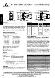
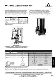
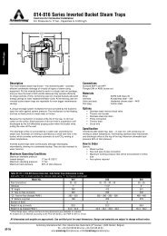
Inverted Bucket Drain Traps<br />
For Heavy Oil/Water Service<br />
BVSW inverted bucket drain traps are designed for systems<br />
with heavy oil or water services.<br />
An inverted bucket is used because the discharge valve is at<br />
the top, so oil is discharged first and the trap body is almost<br />
completely filled with water at all times.<br />
BVSW stands for Bucket Vent Scrubbing Wire. This 1,6 mm<br />
diameter wire swings freely from the trap cap and extends<br />
through the bucket vent. Its function is to prevent reduction of<br />
vent size by buildup of solids or heavy oil in the vent itself. The<br />
up-and-down motion of the bucket relative to the vent scrubbing<br />
wire keeps the vent clean and full size.<br />
Operation of Inverted Bucket Drain Traps<br />
1. Since there is seldom sufficient accumulation of water to<br />
float the bucket and close the valve, the trap must be primed<br />
on initial start-up or after draining for cleaning. Step 1 shows<br />
“after operating” primed condition with oil in the top of bucket<br />
and a very thin layer of oil on top of water in the trap body.<br />
2. When valve in line to trap is opened, air enters bucket,<br />
displacing liquid. When bucket is two-thirds full of air, it<br />
becomes buoyant and floats. This closes the discharge<br />
valve. As bucket rises, the vent scrubbing wire removes oil<br />
and any dirt from bucket vent.<br />
Both liquid and air in trap are at full line pressure, so no<br />
more liquid or air can enter trap until some liquid or air<br />
escapes through the discharge valve. Static head forces air<br />
through bucket vent. The air rises to top of trap and<br />
displaces water that enters bucket at bottom to replace air<br />
that passes through vent. Just as soon as bucket is less<br />
than two-thirds full of air, it loses buoyancy and starts to pull<br />
on valve lever as shown in Step 3.<br />
Figure LD-420-1. Operation of the BVSW Inverted Bucket Drain Trap<br />
Water<br />
<strong>Guidelines</strong> for <strong>Draining</strong><br />
<strong>Liquid</strong>s<br />
Oil<br />
Air Bubbles<br />
Air Under Pressure<br />
1. Trap primed, air off, bucket down, trap<br />
valve open.<br />
2. Trap in service, bucket floating. Air<br />
passes through bucket vent and<br />
collects at top of trap.<br />
LD-420<br />
Armstrong International SA • Parc Industriel des Hauts-Sarts (2 e Avenue) • 4040 Herstal • Belgium<br />
Tel.: +32 (0)4 240 90 90 • Fax: +32 (0)4 240 40 33<br />
www.armstronginternational.eu • info@armstronginternational.eu
Inverted Bucket Drain Traps<br />
3. Note that liquid level at top of trap has dropped and the<br />
liquid level in the bucket has risen. The volume of water<br />
displaced by air exactly equals the volume of water that<br />
entered the bucket. During this valve-closed part of the<br />
operating cycle – Steps 2 and 3 – water and oil are<br />
collecting in the horizontal line ahead of the trap. When the<br />
bucket is about two-thirds full of liquid, it exerts enough pull<br />
on lever to crack open the discharge valve.<br />
4. Two things happen simultaneously. a) The accumulated air<br />
at top of trap is discharged immediately, followed by oil and<br />
any water that enters the trap while the valve is cracked. b)<br />
Pressure in trap body is lowered slightly, allowing<br />
accumulated liquid in horizontal line to enter the trap. Air<br />
displaces liquid from the bucket until it floats and closes the<br />
discharge valve, restoring the condition shown in Step 2.<br />
5. When full buoyancy is restored, the trap bucket is two-thirds<br />
full of air. Oil that has entered while trap was open flows<br />
under bottom of bucket and rises to top of water in trap<br />
body. The trap normally discharges small quantities of air<br />
several times per minute.<br />
<strong>Guidelines</strong> for <strong>Draining</strong><br />
<strong>Liquid</strong>s<br />
3. Water enters bucket to replace air<br />
passing through bucket vent. This<br />
increases weight of bucket until…<br />
4. …pull on lever cracks valve. Air at top<br />
of trap escapes, followed by oil and<br />
water. <strong>Liquid</strong> in pipe ahead of trap<br />
enters bucket followed by air.<br />
5. Air displaces liquid and excess oil<br />
from bucket, restoring condition shown<br />
in Step 2.<br />
Armstrong International SA • Parc Industriel des Hauts-Sarts (2 e Avenue) • 4040 Herstal • Belgium<br />
Tel.: +32 (0)4 240 90 90 • Fax: +32 (0)4 240 40 33<br />
www.armstronginternational.eu • info@armstronginternational.eu<br />
LD-421
Float Type Drain Traps<br />
Closed Float<br />
Hollow, thin-wall metal floats are attached through linkages to<br />
valves at the trap bottom, and a seat with an appropriately sized<br />
orifice is inserted at the trap outlet. Floats are selected to<br />
provide adequate buoyancy to open the valve against the<br />
pressure difference. Discharge usually is to atmosphere, so the<br />
pressure drop is equal to the system air pressure. The float and<br />
linkage are made of stainless steel, and the valve and seat are<br />
hardened stainless steel for wear resistance and long life. The<br />
body is cast iron, stainless steel, or cast or forged steel<br />
depending on gas pressure. Bodies may be made of stainless<br />
steel to resist corrosive gas mixtures.<br />
Entering liquid drops to the bottom of the body. As liquid level<br />
rises, the ball is floated upward, thereby causing the valve to<br />
open sufficiently that outlet flow balances inlet flow. Subsequent<br />
change of incoming flow raises or lowers water level further<br />
opening or throttling the valve. Thus discharge is proportionally<br />
modulated to drain liquid completely and continuously. However,<br />
gas flow may be constant or it may abruptly change depending<br />
on system demand characteristics. <strong>Liquid</strong> formation may be<br />
sporadic, or the nature of flow generation may cause surges. At<br />
times, flow will be very low, requiring operation to throttle the<br />
flow or even tight shut-off. Tightness of closure, gas leakage<br />
and trap cost will depend on the design of linkage and valve.<br />
Free Floating Lever<br />
The discharge from the Model 1-LD is continuous. The opening<br />
of the valve is just wide enough to remove the liquid as fast as it<br />
comes to the trap. Thus, at times, the valve is barely cracked<br />
from its seat.<br />
Water<br />
Figure LD-422-1. Operation of the Model 1-LD Free Floating Lever Drain Trap<br />
As water begins to fill the body of the trap, the float rises, opening the discharge valve.<br />
Motion of the free floating valve lever is guided to provide precise closure.<br />
<strong>Guidelines</strong> for <strong>Draining</strong><br />
<strong>Liquid</strong>s<br />
Free Floating Linkage Valve<br />
A hemispherical ball-shaped valve is attached to linkage which<br />
is suspended freely on two guide pins. There is no fixed pivot or<br />
rigid guides; therefore, the attachment is loose. There are no<br />
critical alignments, and the lever and valve may move in all<br />
directions. Consequently, the lever may move the valve to the<br />
Figure LD-422-2. Free Floating Linkage<br />
seat in any alignment. As the valve approaches the seat, the<br />
pressure pushes the round valve into the square edge orifice of<br />
the seat, effecting a line seal to attain bubble-tight closure.<br />
LD-422<br />
Armstrong International SA • Parc Industriel des Hauts-Sarts (2 e Avenue) • 4040 Herstal • Belgium<br />
Tel.: +32 (0)4 240 90 90 • Fax: +32 (0)4 240 40 33<br />
www.armstronginternational.eu • info@armstronginternational.eu
Float Type Drain Traps<br />
Fixed Pivot Conical Valve<br />
A conically shaped valve is attached to a fixed pivot leverage<br />
system. The fixed pivot does not allow the valve to move freely<br />
to conform to the seat for tight closure. Thus, it may not seal<br />
tightly, and some loss of air or gas may be expected.<br />
Water<br />
Figure LD-423-1. Operation of Model 21 Fixed Pivot Drain Trap<br />
As the water level rises, the ball float cracks the valve to drain liquid at the same rate that it reaches the trap.<br />
Changes in the rate of flow to the trap adjust the float level and the degree of opening of the valve.<br />
Snap Action Valve<br />
Because of the sporadic liquid flow, much of the time the valve<br />
in a standard float-type drainer is only slightly opened. If there is<br />
fine dirt or grit in the liquid, particles may accumulate and clog<br />
the partially open valve, or they may lodge between the valve<br />
and seat, preventing closure. To overcome this, a special togglespring<br />
operated valve is used.<br />
A flat spring attached to the leverage system holds the valve<br />
closed until liquid level is high enough for the buoyancy to<br />
exceed the spring force. Then the valve is snapped open, and<br />
the accumulated dirt and grit can be flushed through the wide<br />
open valve. When the body is nearly empty, buoyancy is<br />
reduced enough to permit the spring to snap the valve closed.<br />
Figure LD-423-2. Operation of Model 71-A Snap Action Drain Trap<br />
Water<br />
<strong>Guidelines</strong> for <strong>Draining</strong><br />
<strong>Liquid</strong>s<br />
Closed About to Open Open<br />
Filling Cycle. Trap valve has just closed.<br />
Spring bowed to right. Float rides high in<br />
water because no force is exerted on<br />
spring. As water enters, float rises, storing<br />
energy in spring. This increases<br />
submergence of float.<br />
Float now is more than half submerged<br />
and spring has assumed a “handlebar<br />
mustache” shape. Energy stored in spring<br />
is due to increased displacement of<br />
water. A very slight rise in water level<br />
causes spring to snap to the left…<br />
…Instantly the valve opens wide. This<br />
releases energy from spring and float<br />
again rides high in water. As water level<br />
drops, weight of float bends spring to<br />
right, causing snap closing of valve before<br />
all the water has been discharged.<br />
Armstrong International SA • Parc Industriel des Hauts-Sarts (2 e Avenue) • 4040 Herstal • Belgium<br />
Tel.: +32 (0)4 240 90 90 • Fax: +32 (0)4 240 40 33<br />
www.armstronginternational.eu • info@armstronginternational.eu<br />
LD-423
Drain Trap Selection<br />
To obtain the full benefits from the traps described in the<br />
preceding section, it is necessary that the correct size and<br />
pressure of drain trap be selected for each job, and that it be<br />
properly installed and maintained.<br />
Rely on Experience. Most drain traps are selected on the<br />
basis of experience. This may be:<br />
n Your personal experience<br />
n The experience of your Armstrong Representative or<br />
distributor<br />
n The experience of thousands of others in draining identical<br />
equipment<br />
Do-It-Yourself Sizing is required at times. Fortunately, drain<br />
trap sizing is simple when you know or can figure:<br />
1. <strong>Liquid</strong> loads in kg/h.<br />
2. Pressure differential.<br />
3. Maximum allowable pressure.<br />
1. <strong>Liquid</strong> Load. Each “How To” section of this handbook<br />
contains formulas and useful information on proper sizing<br />
procedures and safety factors.<br />
Operating differential. When the plant is operating at capacity,<br />
the pressure at the trap inlet may be lower than main pressure.<br />
And the pressure in the return header may go above<br />
atmospheric.<br />
If the operating differential is at least 80% of the maximum<br />
differential, it is safe to use maximum differential in selecting<br />
traps.<br />
IMPORTANT: Be sure to read the discussion on page LD-425,<br />
which deals with less common, but important, reductions in<br />
pressure differential.<br />
3. Maximum Allowable Pressure. The trap must be able to<br />
withstand the maximum allowable pressure of the system, or<br />
design pressure. It may not have to operate at this pressure, but<br />
it must be able to contain it. As an example, the maximum inlet<br />
pressure is 10 barg and the return line pressure is 1 barg. This<br />
results in a differential pressure of 9 bar; however, the trap must<br />
be able to withstand 10 barg maximum allowable pressure. See<br />
Fig. LD-424-1.<br />
2. Pressure Differential. Maximum differential is the difference<br />
between main pressure, or the downstream pressure of a PRV,<br />
and return line pressure. See Fig. LD-424-1. The drain trap must<br />
be able to open against this pressure differential.<br />
<strong>Guidelines</strong> for <strong>Draining</strong><br />
<strong>Liquid</strong>s<br />
Differential Pressure or<br />
Maximum Operating Pressure (MOP)<br />
A<br />
B<br />
Inlet Pressure or<br />
Maximum Allowable<br />
Pressure (MAP)<br />
Trap<br />
Back Pressure or<br />
Vacuum<br />
Figure LD-424-1. “A” minus “B” is Pressure Differential: If “B” is<br />
back pressure, subtract it from “A.” If “B” is vacuum, add it to “A.”<br />
LD-424<br />
Armstrong International SA • Parc Industriel des Hauts-Sarts (2 e Avenue) • 4040 Herstal • Belgium<br />
Tel.: +32 (0)4 240 90 90 • Fax: +32 (0)4 240 40 33<br />
www.armstronginternational.eu • info@armstronginternational.eu
Drain Trap Selection<br />
Factors Affecting Pressure Differential<br />
Pressure Differential in Detail<br />
Inlet Pressure can be:<br />
1. Air main pressure.<br />
2. Reduced pressure controlled by a pressure reducing valve<br />
station.<br />
Discharge can be:<br />
1. Atmospheric.<br />
2. Below atmospheric – under vacuum. Add vacuum to inlet<br />
pressure to get pressure differential.<br />
102,4 mm Hg vacuum = approximately 0,1 bar of pressure<br />
below atmospheric.<br />
3. Above atmospheric due to:<br />
a. Pipe friction<br />
b. Elevating liquid<br />
Every 1 m lift reduces pressure differential by approximately 0,1<br />
bar, when the discharge is only liquid.<br />
Special Considerations<br />
Drain traps are available for services other than those found on<br />
standard compressed air systems.<br />
High Pressure<br />
Spring-loaded mechanisms allow float type drain traps to<br />
operate on pressures above 200 bar.<br />
Fluids Other Than Water<br />
Different fluids, such as oils and liquid, can be compensated for<br />
with specially weighted floats or lower operating pressure<br />
ratings. Fluids with specific gravities down to 0,4 will work with<br />
float type drain traps.<br />
Materials of Construction<br />
Service requirements for stainless steel or other corrosionresistant<br />
materials can be met by float and inverted bucket type<br />
drain traps.<br />
NACE Sour Gas Service<br />
Special materials and construction are required for hydrogen<br />
sulfide service.<br />
High Capacity for Large Flow Rates<br />
Ultra-capacity type drain traps allow float type drain traps to be<br />
used on service requiring capacities up to 320 000 kg/h.<br />
Dual Gravity<br />
Float type drain traps can be modified to drain a heavier fluid<br />
from a lighter fluid.<br />
0,9 bar<br />
0,8 bar<br />
0,7 bar<br />
0,6 bar<br />
0,5 bar<br />
9 m<br />
8 m<br />
7 m<br />
6 m<br />
5 m<br />
Trap<br />
Pressure drop<br />
over water seal<br />
to lift cold<br />
condensate<br />
0,4 bar<br />
0,3 bar<br />
0,2 bar<br />
0,1 bar<br />
4 m<br />
3 m<br />
2 m<br />
1 m<br />
Air Main<br />
Water<br />
Air<br />
<strong>Guidelines</strong> for <strong>Draining</strong><br />
<strong>Liquid</strong>s<br />
Water Seal<br />
Lift in meters<br />
Figure LD-425-1. <strong>Liquid</strong> from gravity drain point is lifted to trap<br />
by a syphon. Every meter of lift reduces pressure differential by<br />
approximately 0,1 bar. Note seal at low point and the trap’s<br />
internal check valve to prevent back flow.<br />
Armstrong International SA • Parc Industriel des Hauts-Sarts (2 e Avenue) • 4040 Herstal • Belgium<br />
Tel.: +32 (0)4 240 90 90 • Fax: +32 (0)4 240 40 33<br />
www.armstronginternational.eu • info@armstronginternational.eu<br />
LD-425
How to Drain Air Distribution Systems<br />
Air distribution systems make up the vital link between<br />
compressors and the vast amount of air-utilizing equipment.<br />
They represent the method by which air is actually transported<br />
to all parts of the plant to perform specific functions.<br />
The three primary components of air distribution systems are<br />
air mains, air branch lines, and air distribution manifolds. They<br />
each fill certain requirements of the system, and together with<br />
separators and traps, contribute to efficient air utilization.<br />
Common to all air distribution systems is the need for drip legs<br />
at various intervals. These drip legs are provided to:<br />
Air mains are one of the most common applications for drain<br />
traps. These lines need to be kept free of liquid to keep the<br />
supplied equipment operating properly. Inadequately trapped air<br />
mains often result in water hammer and slugs of liquid, which<br />
can damage control valves and other equipment. There is also<br />
a freeze potential wherever water is allowed to accumulate. In<br />
areas where air is moving slowly, the accumulation of water can<br />
effectively reduce the pipe size, thereby increasing the pressure<br />
drop and wasting energy.<br />
1. Let liquid escape by gravity from the fast-moving air.<br />
2. Store the liquid until the pressure differential can discharge it<br />
through the drain trap.<br />
3. Serve as dirt pockets for the inevitable dirt and grit that will<br />
accumulate in the distribution system.<br />
Min. 3/4''<br />
Drain<br />
Min. 3/4''<br />
Float Drain Trap<br />
Drain<br />
Figure LD-426-1.<br />
Drain trap installed straight under a low<br />
point.<br />
Figure LD-426-2.<br />
Series 200 or 300 inverted bucket drain<br />
traps installed on compressed air line<br />
contaminated by oil.<br />
Figure LD-426-3.<br />
Series 800 or 900 inverted bucket drain<br />
traps installed on compressed air line<br />
contaminated by oil.<br />
<strong>Guidelines</strong> for <strong>Draining</strong><br />
<strong>Liquid</strong>s<br />
Table LD-426-1. Recommendation Chart<br />
(See chart on LD-415 for “Feature Code” references.)<br />
Equipment Being<br />
Drained<br />
Air Mains<br />
1st Choice and<br />
Feature Code<br />
FF<br />
B, C, D, J, M<br />
* IB is a good alternative where heavy oil carryover is likely.<br />
Alternate Choice and<br />
Feature Code<br />
FP*<br />
Figure LD-426-4. Drip leg length should be at least 1,5 times<br />
the diameter of the main and never less than 10". Drip leg<br />
diameter should be the same size as the main, up to 4" pipe<br />
size and at least 1/2 of the diameter of the main above that, but<br />
never less than 4".<br />
LD-426<br />
Armstrong International SA • Parc Industriel des Hauts-Sarts (2 e Avenue) • 4040 Herstal • Belgium<br />
Tel.: +32 (0)4 240 90 90 • Fax: +32 (0)4 240 40 33<br />
www.armstronginternational.eu • info@armstronginternational.eu
How to Drain Air Distribution Systems<br />
Selection of Drain Traps and Safety Factor for Air Mains<br />
Traps should be selected to discharge a volume of liquid<br />
normally produced when the system is up and running. <strong>Liquid</strong><br />
loads can be estimated if actual air volume flow is not known. If<br />
cold temperatures are possible, the dew point at supply<br />
pressure must be known. Once this maximum is determined,<br />
the safety factor used to size the trap will be only 10% of the<br />
total potential liquid load. Ten percent of the total is used<br />
because most of the liquid has been removed in the aftercooler<br />
and receiver. The drain trap must handle only the small<br />
remaining amount of 10% of the total possible load.<br />
Rule of Thumb for Calculating Compressor <strong>Liquid</strong> Loads<br />
flow in m³/h x 44,14 g/m³ x 60 min/h<br />
1000 g/kg<br />
= kg/h<br />
1. Assuming worst condition:<br />
38°C @ 100% RH<br />
For other conditions, see page LD-416<br />
2. Using air main safety factor of: Load x 10%<br />
Installation of Drain Traps on Air Mains<br />
Drip Legs. All air mains should utilize drip legs and traps at all<br />
low spots or natural drainage points, such as ahead of risers,<br />
end of mains, ahead of expansion joints or bends, and ahead of<br />
valves and regulators (see installation Fig. LD-426-4).<br />
Where there are no natural drainage points, drip legs and drain<br />
traps should still be provided. These should normally be<br />
installed at intervals of about 150 m.<br />
<strong>Guidelines</strong> for <strong>Draining</strong><br />
<strong>Liquid</strong>s<br />
Armstrong International SA • Parc Industriel des Hauts-Sarts (2 e Avenue) • 4040 Herstal • Belgium<br />
Tel.: +32 (0)4 240 90 90 • Fax: +32 (0)4 240 40 33<br />
www.armstronginternational.eu • info@armstronginternational.eu<br />
LD-427
How to Drain Air Distribution Systems<br />
Branch Lines<br />
Branch lines are takeoffs of the air main supplying specific<br />
areas of air-utilizing equipment. Branch lines must always be<br />
taken from the top of the air main. The entire system must be<br />
designed and hooked up to prevent accumulation of liquid at<br />
any point. If a specific process area requires it, an air dryer will<br />
be installed on the branch line.<br />
Trap Selection and Safety Factor for Branches<br />
The formula for computing liquid load in branch lines is the<br />
same as that used for air mains. Branch lines also have a<br />
recommended safety factor of 10% of total air load. Drip legs<br />
must be installed ahead of risers and at the end of branch lines,<br />
especially when branch line runouts exceed 15 m. There are<br />
usually several branches off the air main, and in many cases<br />
they experience a high liquid load when they run against cold<br />
outside walls. This cooling causes more moisture to condense<br />
in the branch line than would be seen in the air main.<br />
Distribution Manifolds<br />
A distribution manifold is a terminal for a branch line from which<br />
several air users are taken off. They are particularly common in<br />
manufacturing facilities for pneumatic tool hookups or takeoffs<br />
to cylinder actuators. Like branch lines, it is common for<br />
distribution manifolds to be installed against cool walls where<br />
low temperatures cause condensation and the accumulation of<br />
liquid.<br />
Since the air distribution manifold is usually one pipe size larger<br />
than the branch line, it is common for air velocity to drop when<br />
coming from the branch line. With this decrease in velocity,<br />
often combined with lower ambient temperatures, it is common<br />
for a liquid to accumulate in the distribution manifold. For this<br />
reason, the use of filter-drainer combinations or separate drain<br />
traps is recommended. Trapping the liquid in the distribution<br />
manifold is important to protect the regulators on air-using<br />
equipment and orifices in air-using instruments.<br />
This is a location where manual valves are commonly misused<br />
due to their accessibility. To drain the liquid and keep it from<br />
fouling an instrument or pneumatic tool, manual valves will often<br />
be cracked to atmosphere. When they are left this way, the<br />
result is a large air loss due to the unrestricted free blow of air<br />
to atmosphere.<br />
Trap Selection and Safety Factor for Distribution Manifolds<br />
Normally the smallest drain trap is practical for distribution<br />
manifolds up to manifold diameters of 2''. Above 2'', the<br />
distribution manifold should be considered a branch, and then<br />
the sizing procedure from the Air Main section would apply.<br />
Distribution manifolds are often equipped with filters and<br />
regulators. Regulators may also be found at the termination<br />
before the air-using device.<br />
<strong>Guidelines</strong> for <strong>Draining</strong><br />
<strong>Liquid</strong>s<br />
Table LD-428-1. Recommendation Chart<br />
(See chart on LD-415 for “Feature Code” references.)<br />
Equipment Being<br />
Drained<br />
1st Choice and<br />
Feature Code<br />
Branch Lines<br />
FF<br />
B, C, D, J, M<br />
Distribution Manifolds<br />
FF<br />
B, C, D, I, M<br />
* IB is a good alternative where heavy oil carryover is likely.<br />
Alternate Choice<br />
FP*<br />
FP<br />
LD-428<br />
Armstrong International SA • Parc Industriel des Hauts-Sarts (2 e Avenue) • 4040 Herstal • Belgium<br />
Tel.: +32 (0)4 240 90 90 • Fax: +32 (0)4 240 40 33<br />
www.armstronginternational.eu • info@armstronginternational.eu
How to Drain Air Distribution Systems<br />
Installation<br />
The ABCs of trap installation must be followed: “A” for<br />
accessible, “B” for below the point being drained, and “C” for<br />
close to the point being drained. If the discharge point for this<br />
drain trap is some distance away from the drain point, the<br />
discharge line from the trap should be run out – not the inlet to<br />
the trap.<br />
When installing traps on the drain connection of filters,<br />
particular care should be taken to the connection size. Normally<br />
outlet connections on filters are 1/4'' in size or less. This<br />
connection size is normally not large enough to allow anything<br />
but slugs of liquid to flow into the trap housing. If a float trap is<br />
utilized, it should be either back vented or the connection size<br />
must be increased to 3/4'' minimum. For additional installation<br />
recommendations, see pages LD-464 and LD-465.<br />
Table LD-429-1. Correction Factors<br />
For grams of water condensed at temperatures other than 27°C<br />
find weight condensed at 27°C and multiply by factors shown<br />
°C Factor °C Factor °C Factor °C Factor<br />
-12 0,070 10 0,373 38 1,81 60 5,15<br />
-7 0,112 16 0,525 43 2,39 65 6,52<br />
-1 0,176 21 0,729 49 3,12 71 8,19<br />
5 0,259 32 1,35 54 4,02 77 10,2<br />
Chart LD-429-1. Water Condensed From Compressed Air<br />
19<br />
100% RH<br />
18<br />
90% RH<br />
Grams of water condensed per m³ of compressed air at 27°C<br />
(Compressor rating: 1 700 m³/h)<br />
17<br />
15<br />
14<br />
13<br />
12<br />
10<br />
9<br />
8<br />
7<br />
5<br />
4<br />
3<br />
1,3<br />
80% RH<br />
70% RH<br />
60% RH<br />
50% Humidité Relative<br />
40%RH<br />
30%RH<br />
20%RH<br />
10%RH<br />
<strong>Guidelines</strong> for <strong>Draining</strong><br />
<strong>Liquid</strong>s<br />
0<br />
1,7 3,4 5,1 6,9 8,6 10 12 14 16 17 21 24 28 35 41 48 45<br />
Pressure in bar<br />
Note: Amount of water condensed is in direct ratio to<br />
compressor rating. For example, for 850 m³/h compressor,<br />
multiply determined amount of condensate by 0,50; for 340<br />
m³/h compressor, multiply amount of condensate by 0,20.<br />
Armstrong International SA • Parc Industriel des Hauts-Sarts (2 e Avenue) • 4040 Herstal • Belgium<br />
Tel.: +32 (0)4 240 90 90 • Fax: +32 (0)4 240 40 33<br />
www.armstronginternational.eu • info@armstronginternational.eu<br />
LD-429
How to Drain Intercoolers, Aftercoolers and Aftercooler<br />
Separator Combinations<br />
Aftercooler<br />
An aftercooler serves as the primary means of moisture<br />
removal on industrial air systems. It increases the efficiency of<br />
air distribution by reducing pressure drop created when air flows<br />
through the system. It does this by using cooling water to<br />
reduce the specific volume of the air which, in turn, allows the<br />
air to flow through the system with less pressure drop.<br />
Aftercoolers are found on most industrial compressors over 7,5<br />
kw in size. In addition to removing the heat of compression,<br />
aftercoolers also remove approximately two-thirds of the liquid<br />
found in the air, and help in the removal and knock-down of oil<br />
carryover from the compressor.<br />
Intercooler<br />
Select the proper trap for:<br />
1. Entering water temperature into the intercooler.<br />
2. Airflow rate through the intercooler.<br />
3. Intermediate pressure at which the intercooler is operated.<br />
Use Chart LD-429-1 on page LD-429, “Water Condensed From<br />
Compressed Air” to determine the grams of water condensed<br />
per m³. Then multiply by the compressor rating (1 700 m³/h) and<br />
divide by 1000 to get the water flow in kg/h. Then use a safety<br />
factor of 2:1.<br />
Intercooler<br />
Compressor intercoolers are designed to increase the efficiency<br />
of compression by reducing the temperature and specific<br />
volume of air between stages of compression. This allows the<br />
compressor to do more work at a lower temperature than would<br />
normally occur. Because some condensing will occur in the<br />
intercooler, a drain trap is required to protect compressor parts.<br />
If liquid were to carry over from the intercooler, it could also<br />
carry dirt or scale into the compressor and/or also cause<br />
corrosion within the compressor, both of which are undesirable<br />
for efficient compressor operation. If slugs of liquid were to pass<br />
from the intercooler into the compressor, it would make the<br />
compressor operation erratic. Efficient trapping is required at<br />
this point to deliver dry air to the next stage of the compressor.<br />
An intercooler is typically a shell and tube heat exchanger.<br />
<strong>Liquid</strong> condensate flow out of the heat exchanger is usually<br />
irregular, causing slugs to accumulate and pass into the drain<br />
trap. Because of this, a drip leg is required on the intercooler,<br />
and full size outlet piping from the intercooler must be used into<br />
a dirt pocket. The drip leg allows the slug of condensate to be<br />
handled by the drain trap and handles some small backup while<br />
the drain trap is discharging the liquid.<br />
<strong>Guidelines</strong> for <strong>Draining</strong><br />
<strong>Liquid</strong>s<br />
The intercooler may also experience oil carryover if the<br />
compressor is not of the oil-less or sealed type. As air enters<br />
the intercooler, it carries a mist or tiny droplets of oil along with<br />
it. Because the air is at a relatively high temperature, this oil is<br />
fairly thin. Then, as the intercooler cools the air and oil, the oil<br />
may thicken. The drain trap must be able to discharge this oil<br />
before it thickens and negatively affects the drain trap and<br />
intercooler operation. Trap selection is very important in this<br />
type of application where a water and oil mix must be handled<br />
by the trap and the oil must be discharged first.<br />
Since the aftercooler removes approximately two-thirds of the<br />
total moisture load, traps here will normally be much larger than<br />
those found on the rest of the system.<br />
Trap Selection and Safety Factor<br />
Table LD-430-1. Recommendation Chart<br />
(See chart on LD-415 for “Feature Code” references.)<br />
Equipment<br />
Being<br />
Drained<br />
Aftercooler<br />
Air<br />
1st Choice and<br />
Feature Code<br />
IB<br />
F, G, J, K, M<br />
Alternate<br />
Choice<br />
Gas<br />
1st Choice and<br />
Feature Code<br />
Alternate<br />
Choice<br />
Intercooler<br />
* Since IBs vent gas to operate, an FF is suggested because gas venting<br />
may not be desirable.<br />
FF<br />
*FF<br />
B, E, J<br />
FP<br />
LD-430<br />
Armstrong International SA • Parc Industriel des Hauts-Sarts (2 e Avenue) • 4040 Herstal • Belgium<br />
Tel.: +32 (0)4 240 90 90 • Fax: +32 (0)4 240 40 33<br />
www.armstronginternational.eu • info@armstronginternational.eu
How to Drain Intercoolers, Aftercoolers and Aftercooler<br />
Separator Combinations<br />
When selecting the type of trap, consider the failure mode and<br />
the ability of the trap to respond to slugs of liquid. In most<br />
cases, an “open” failure mode will be desirable as it is vital to<br />
protect the compressor from slugs of liquid. A quick response to<br />
slugs is important so there is no delay between the time the<br />
liquid accumulates and the trap discharges the liquid.<br />
Aftercooler<br />
When the aftercooler condensing rate is not known, there are<br />
two typical methods for calculating condensate load. The first<br />
method is to calculate total airflow through the system. Then<br />
using Chart LD-429-1 on page LD-429, titled “Water Condensed<br />
From Compressed Air” determine grams of water condensed<br />
per m³. Multiply this by the compressor rating (1 700 m³/h) and<br />
divide by 1000 for required trap capacity in kg per hour (the<br />
entering maximum incoming summertime temperature and<br />
relative humidity must be known to use this chart). This load is<br />
then multiplied by 2 to determine required trap capacity.<br />
The second method of calculating trap capacity is to look at<br />
maximum allowable flow rate through the aftercooler. Use the<br />
“Water Condensed From Compressed Air” chart on page<br />
LD-429 in the same manner as described in Method 1.<br />
Although this method will normally yield a larger trap size, it<br />
allows for the addition of another compressor or the<br />
interconnection of several compressors to the system in the<br />
event of unplanned by-passes.<br />
In the second method, it’s important to estimate the average<br />
water temperature within the aftercooler as closely as possible.<br />
Not all air actually comes in contact with the water tubes;<br />
therefore, the air is not uniformly cooled to the water<br />
temperature. If actual leaving air temperature is known, this is<br />
by far the most accurate figure to use. A properly sized<br />
aftercooler will normally cool compressed air down to within<br />
10°C lower than entering air temperature.<br />
Installation<br />
When installing drain traps on aftercoolers or aftercooler<br />
separator combinations, the “ABCs” of trap installation should<br />
be followed:<br />
Accessible for maintenance and repair.<br />
Below the point being drained.<br />
Close to the drip point as possible.<br />
Be sure to follow manufacturer’s instructions on trap installation.<br />
Most aftercoolers are equipped with a separate separator.<br />
However, if a separator is not furnished, the aftercooler must be<br />
trapped individually. In the case of the aftercooler/separator<br />
combination, only the separator normally requires a trap. See<br />
Fig. LD-431-1 or LD-431-2. But again, it is important to follow<br />
manufacturer’s instructions. For additional installation<br />
recommendations, see pages LD-464 and LD-465.<br />
Air Separator<br />
Air Separator<br />
<strong>Guidelines</strong> for <strong>Draining</strong><br />
<strong>Liquid</strong>s<br />
Drain<br />
Drain<br />
Figure LD-431-1. Installation of a 200 Series inverted bucket<br />
drain trap on compressed air contaminated by oil.<br />
Figure LD-431-2. 800 Series inverted bucket drain trap<br />
installed on compressed air contaminated by oil.<br />
Armstrong International SA • Parc Industriel des Hauts-Sarts (2 e Avenue) • 4040 Herstal • Belgium<br />
Tel.: +32 (0)4 240 90 90 • Fax: +32 (0)4 240 40 33<br />
www.armstronginternational.eu • info@armstronginternational.eu<br />
LD-431
How to Drain Separators, Separator Filter Combinations<br />
Separators serve an important function within the compressed<br />
air system. Separators may also be known as knockout pots,<br />
knockout drums or demisters. Their function is to remove liquid<br />
that may be moving at a high speed from the flowing air, and<br />
they normally perform this function in a two-step process.<br />
1. Separators increase the flow area and volume of the gas,<br />
thereby reducing its velocity. Air within the system may flow<br />
at velocities exceeding 45 m/s. At this velocity any liquid will<br />
be entrained as droplets and will not be flowing along the<br />
bottom of the pipe. To remove these liquid droplets, it is<br />
necessary to reduce the velocity of the gas; otherwise, the<br />
droplets accumulate and again become entrained with the<br />
flowing gas.<br />
2. The second step is to change direction and impinge the<br />
liquid. As the velocity of the gas is reduced, the velocity of<br />
the fast-moving droplets can be reduced even further by<br />
causing the air to take either 90-degree turns or to<br />
centrifugally flow within a chamber. Both of these methods<br />
serve to “sling” the droplets up against baffles, plates or the<br />
wall of the separator.<br />
Because the droplets have a relatively high mass and are<br />
incompressible, their velocity will drop dramatically. At this point,<br />
gravity will take over, causing the drops to accumulate and flow<br />
into the bottom of the separator. <strong>Liquid</strong> will often fall in sheets<br />
down the wall of the separator and collect at the outlet piping in<br />
slugs. The immediate drainage of the slugs is important since<br />
the separator is normally a final opportunity to protect an airusing<br />
device downstream.<br />
Locations<br />
Separators are normally located on the leaving side of<br />
aftercoolers and before the compressed air receiver. They are<br />
often integral with filters located before sensitive air-using<br />
equipment or as part of the filter on a distribution manifold. In<br />
this case there may be a combination filter, oiler, regulator and<br />
separator drainage point for liquids to accumulate.<br />
Trap Selection and Safety Factor<br />
If the separator is part of an aftercooler combination installed<br />
between the compressor and the receiver, you should refer to<br />
the section on Aftercoolers and Aftercooler Separators for trap<br />
selection.<br />
Trap selection is fairly critical, especially on equipment with<br />
larger than 1" air lines feeding it, since slug formation can wash<br />
scale into the air-using equipment and become a serious dirt<br />
problem. Therefore, on larger than 1" separators, the flow<br />
should be calculated by totaling the air consumption of the<br />
devices downstream and using Chart LD-429-1, “Water<br />
Condensed From Compressed Air” on page LD-429. Use the<br />
full water load expected and the safety factor of 3:1 to figure<br />
trap capacity.<br />
If liquid is allowed to accumulate for any amount of time, it may<br />
undermine the entire purpose and function of the separator.<br />
Therefore, if the separator does not do its job efficiently, it can<br />
actually become a reservoir that accumulates condensate and<br />
forms slugs to be transmitted down the air line and into the<br />
device being protected. In this case, the use of a separator may<br />
be worse than no protection at all.<br />
<strong>Guidelines</strong> for <strong>Draining</strong><br />
<strong>Liquid</strong>s<br />
Table LD-432-1. Recommendation Chart<br />
(See chart on LD-415 for “Feature Code” references.)<br />
Equipment Being Drained<br />
1st Choice and<br />
Feature Code<br />
Separator Line Size > 1"<br />
FF*<br />
Separator Inlet Pipe > 1" J, B, C, E<br />
* IB is a good alternative where heavy oil carryover is likely.<br />
Alternate Choice<br />
IB<br />
FP*<br />
LD-432<br />
Armstrong International SA • Parc Industriel des Hauts-Sarts (2 e Avenue) • 4040 Herstal • Belgium<br />
Tel.: +32 (0)4 240 90 90 • Fax: +32 (0)4 240 40 33<br />
www.armstronginternational.eu • info@armstronginternational.eu
How to Drain Separators, Separator Filter Combinations<br />
To determine proper trap capacity for separators with a pipe<br />
size of less than 1", the flow can be estimated by using Chart<br />
LD-429-1, “Water Condensed From Compressed Air” on page<br />
LD-429, and then calculating 20% of full load.<br />
The safety factor for both selection procedures is 3:1 since<br />
separators must respond to surges of liquid from the inlet. In<br />
this case, the trap must handle far more liquid than would be<br />
experienced under normal operation.<br />
Installation<br />
When installing ball float type traps on separators 1" and above,<br />
it’s important to back vent the trap (refer to the section on how<br />
to hook up ball floats for the purpose and function of back vent<br />
lines, page LD-464). All other types of drainers should be<br />
coupled as closely as possible to the drain leg. The drain leg<br />
should be the same size as the drain connection on the<br />
separator and extend 150 mm below the separator with another<br />
150 mm allowed for a dirt pocket. The trap is then tee’d off this<br />
line (see Figs. LD-433-1 and LD-433-2). This piping is crucial<br />
because, as noted above, if the separator does not receive full<br />
drainage, it can be worse than no separator at all. For this<br />
reason, the “ABCs” are critical:<br />
Accessible for inspection and maintenance.<br />
Below the equipment being drained.<br />
Close to the drain point.<br />
The line size leading from the drip leg to the inlet of the unit<br />
should be kept the same size as the trap inlet for good drainage<br />
into the trap. Again, when slugs are being handled it’s important<br />
that the trap begin draining immediately. Back vents on float<br />
type traps should be a minimum of 1/2" in pipe size with 3/4"<br />
preferred. Any valves used in this back-vent piping should be<br />
full ported to allow free gas flow out of and liquid flow into the<br />
drain trap. For additional installation recommendations, see<br />
pages LD-464 and LD-465.<br />
Back-Vent Line<br />
Air Separator<br />
Air Separator<br />
Drain Leg<br />
Float Drain Trap<br />
With Vent<br />
Connection<br />
Dirt<br />
Pocket<br />
3/4'' Pipe Pitch<br />
Down Minimum<br />
6 mm Per 300 mm<br />
Float Drain<br />
Trap<br />
<strong>Guidelines</strong> for <strong>Draining</strong><br />
<strong>Liquid</strong>s<br />
Dirt Pocket<br />
Drain<br />
Drain<br />
Figure LD-433-1. Installation of a drain trap with equalizing line<br />
downstream of the separator in order to assure a quick and<br />
regular flow to the drainer. Note side inlet connection from<br />
separator.<br />
Figure LD-433-2. Installation of a drain trap on side of<br />
separator.<br />
Armstrong International SA • Parc Industriel des Hauts-Sarts (2 e Avenue) • 4040 Herstal • Belgium<br />
Tel.: +32 (0)4 240 90 90 • Fax: +32 (0)4 240 40 33<br />
www.armstronginternational.eu • info@armstronginternational.eu<br />
LD-433
How to Drain Receivers<br />
Receivers perform the vital function of storing air for the system.<br />
The receiver dampens pressure fluctuations in the system and<br />
provides a very short storage time in the event of compressor<br />
failure. It also functions as a liquid knockout drum to prevent<br />
entrained liquid (which may carry over) from entering the<br />
compressed air dryer or the air mains. The receiver should be<br />
sized to provide enough storage time for an orderly shutdown,<br />
particularly in the case of instrumentation air systems. Receiver<br />
volume is what provides the amount of air required for storage<br />
periods.<br />
The receiver should be located close to the compressor. Fallout<br />
of liquid is normal due to low velocity within the receiver.<br />
Velocity is at the lowest point it will reach in any other part of<br />
the operating system. The air has a high dwell time within the<br />
receiver and is more likely to cool to ambient. This cooling of<br />
the air is what causes moisture to condense.<br />
The receiver is equipped with a drain port at the bottom to allow<br />
liquids to flow to drain traps. In many cases, because receivers<br />
are so large and located adjacent to the compressor, they are<br />
installed close to the floor. When this happens, the drain point is<br />
relatively inaccessible, making trap piping difficult and gravity<br />
flow into the trap often impossible. To avoid this, the receiver<br />
should be located on a small concrete pad, which will facilitate<br />
efficient drain trap installation and operation.<br />
For several reasons, it’s good to keep the receiver drained.<br />
When receiver volume is lost, the dampening of the<br />
compressed air pressure is reduced and the storage time<br />
between compressor failure and system shutdown is greatly<br />
reduced. Corrosion within the receiver can also take place when<br />
liquid is allowed to accumulate.<br />
Manual valves are commonly used to drain receivers since they<br />
are typically installed close to the floor. The resulting loss of<br />
receiver volume is seldom noticed in the day-to-day operation of<br />
the system. However, with any manual system, the valve can be<br />
forgotten and not opened. Then, when the weather changes<br />
from a relatively dry, low moisture load to a warm, high moisture<br />
load, the receiver will lose volume and the dampening effect<br />
and accumulator effect are decreased. The compressor can<br />
short cycle under these conditions, increasing the wear and tear<br />
on the compressor. In addition, the only reminder to open the<br />
manual valve is when carryover occurs. In this case, an air<br />
dryer can be damaged, liquid can be introduced into the air<br />
mains and surge through the system, causing scale to be<br />
washed into the system, water hammer and/or freeze damage.<br />
Trap Selection and Safety Factor<br />
To select the proper trap for the receiver, it is necessary to<br />
calculate total system load using Chart LD-429-1, “Water<br />
Condensed From Compressed Air,” on page LD-429. Once this<br />
total potential load is known, it will be multiplied by the following<br />
factors: With an aftercooler, multiply the load by 50%, with an<br />
aftercooler separator combination, multiply the total load by<br />
40%, and if no aftercooler is present, multiply the total load by<br />
70%. Once this load is known, a safety factor of 2:1 is applied.<br />
Table LD-434-2. Total System Load Multipliers<br />
Calculate Total System<br />
Load with<br />
Aftercooler<br />
Aftercooler<br />
Separator<br />
None<br />
Multiply by 50% 40% 70%<br />
<strong>Guidelines</strong> for <strong>Draining</strong><br />
<strong>Liquid</strong>s<br />
Table LD-434-1. Recommendation Chart<br />
(See chart on LD-415 for “Feature Code” references.)<br />
Equipment Being<br />
Drained<br />
Receivers<br />
* FF for over 55 kg/h<br />
1st Choice and<br />
Feature Code<br />
FS*<br />
C, E, I, J, K<br />
Alternate Choice<br />
IB<br />
D<br />
LD-434<br />
Armstrong International SA • Parc Industriel des Hauts-Sarts (2 e Avenue) • 4040 Herstal • Belgium<br />
Tel.: +32 (0)4 240 90 90 • Fax: +32 (0)4 240 40 33<br />
www.armstronginternational.eu • info@armstronginternational.eu
How to Drain Receivers<br />
Installation<br />
When a float type drain trap is used with a receiver, the level<br />
will run at about the inlet connection on the trap. Therefore, it is<br />
important to locate the trap as close to the floor as feasible and<br />
with no dips in the piping. See Figs. LD-435-1 thru LD-435-4. If<br />
there is a piping dip with a float type unit and the vent<br />
connection is not back vented, the unit will fail to operate. In the<br />
case of a back-vented unit, the dip in the piping will be flooded<br />
at all times. An inverted bucket trap can be installed above floor<br />
level since it will operate above the drain point. An internal<br />
check valve, tube and coupling should be installed to prevent<br />
the liquid seal from flowing backward on system shutdown. A<br />
snap action type float unit should be used when any amount of<br />
grit is expected in the system. In this case, the spring life can be<br />
extended by moving the drain trap slightly upward to allow liquid<br />
to accumulate both within the receiver and within the trap body<br />
between trap cycles. For additional installation<br />
recommendations, see pages LD-464 and LD-465.<br />
Equalizing Line<br />
Receiver<br />
3/4'' Pipe Pitch<br />
Down Minimum<br />
6 mm Per 300 mm<br />
Maximum Water<br />
Level<br />
Float Drain Trap<br />
With Vent<br />
Connection<br />
Float Drain<br />
Trap<br />
Drain<br />
Drain<br />
Figure LD-435-1.<br />
Drain trap installed at side of a receiver, close to floor. Water will<br />
rise to broken line before drain trap opens.<br />
Figure LD-435-2.<br />
Install the drain trap on side to get better access or compensate<br />
for lack of space under the receiver (particularly for drain trap<br />
used under compressors).<br />
Receiver<br />
Receiver<br />
3/4''<br />
3/4''<br />
Float Drain<br />
Trap<br />
Y-Strainer<br />
Float Drain<br />
Trap<br />
<strong>Guidelines</strong> for <strong>Draining</strong><br />
<strong>Liquid</strong>s<br />
Drain<br />
Drain<br />
Figure LD-435-3.<br />
Installation not recommended because of the dirt problem that<br />
can occur with a drain trap installed straight under the receiver.<br />
Figure LD-435-4.<br />
Same installation but with a strainer protecting the drain trap.<br />
Armstrong International SA • Parc Industriel des Hauts-Sarts (2 e Avenue) • 4040 Herstal • Belgium<br />
Tel.: +32 (0)4 240 90 90 • Fax: +32 (0)4 240 40 33<br />
www.armstronginternational.eu • info@armstronginternational.eu<br />
LD-435
How to Drain Dryers<br />
The function of dryers is to eliminate liquid in applications<br />
where freezing or any moisture accumulation can cause serious<br />
problems with the air-consuming equipment. Dryers should<br />
always be installed on instrument quality air systems.<br />
Two basic dryer types are dessicant and refrigerated. In the<br />
dessicant type, the dessicant chemical absorbs the liquid by<br />
chemically bonding with the water molecules. Dessicant dryers<br />
can achieve very low dew points and are often installed with a<br />
pre-dryer of the refrigerant type. Refrigerant dryers work the<br />
same as aftercoolers by circulating cold fluid, causing the<br />
moisture to condense. However, their ability to reach low dew<br />
points is limited by the temperature at which frost will form on<br />
the heat exchanger tubing (greatly reducing heat transfer).<br />
This leads to a discussion of air dew point. Dew point is the<br />
temperature at which moisture will condense out from the air<br />
due to its relative humidity increasing above 100%; see Chart<br />
LD-437-1. When this happens, the moisture condenses out and<br />
can be drained to a drain trap. Dew point is also important when<br />
considering air that has left the dryer, because if the air is ever<br />
exposed to temperatures below its dew point, moisture will<br />
form. Therefore, when applying air dryers, it is important to<br />
consider two features of compressed air usage that will impact<br />
dryer selection.<br />
1. When air is compressed, the dew point is increased. Also,<br />
the dew point under pressurized conditions must be known.<br />
For example, even though a 4°C dew point is achieved at<br />
atmospheric conditions, this becomes a dew point of about<br />
12°C once the air has been compressed to 7 bar. In outdoor<br />
systems, when the temperature drops below 12°C,<br />
condensing and freezing of that moisture will result.<br />
2. When compressed air is expanded through instruments or<br />
air tools, its volume increases, pressure decreases and a<br />
temperature drop is usually experienced. If the temperature<br />
drops below the dew point of the air, undesirable moisture<br />
forms in the equipment. The air would never be subjected to<br />
that temperature under any conditions other than when<br />
expanding.<br />
Air Dryer<br />
3/4'' Pipe Pitch<br />
Down Minimum<br />
6 mm Per 300 mm<br />
Float Drain<br />
Trap<br />
<strong>Guidelines</strong> for <strong>Draining</strong><br />
<strong>Liquid</strong>s<br />
Drain<br />
Figure LD-436-1.<br />
Drain trap installation with dirt leg for purging the dirt.<br />
Table LD-436-1. Recommendation Chart<br />
(See chart on LD-415 for “Feature Code” references.)<br />
Equipment Being<br />
Drained<br />
Dryers<br />
1st Choice and<br />
Feature Code<br />
FF<br />
B, C, J, N<br />
Alternate Choice<br />
IB<br />
FP<br />
LD-436<br />
Armstrong International SA • Parc Industriel des Hauts-Sarts (2 e Avenue) • 4040 Herstal • Belgium<br />
Tel.: +32 (0)4 240 90 90 • Fax: +32 (0)4 240 40 33<br />
www.armstronginternational.eu • info@armstronginternational.eu
How to Drain Dryers<br />
Drain traps are usually required on refrigerated type dryers only.<br />
Here the refrigerant chills air and creates moisture that the drain<br />
trap can discharge. In the case of the dessicant type air dryer,<br />
the chemical grabs the moisture and bonds chemically with the<br />
water molecules, and no liquid accumulates. These bonded<br />
water molecules are then usually driven off in a regeneration<br />
cycle the dryer must periodically undergo.<br />
Trap Selection and Safety Factor<br />
In most cases, the dryer manufacturer will rate the dryer for a<br />
given moisture removal rate. The safety factor should still be<br />
applied to this load, however. If the manufacturer’s ratings are<br />
not known, then it’s necessary to calculate the moisture content<br />
of the air at aftercooler conditions and the moisture content at<br />
ambient conditions. Using the lower moisture content between<br />
these two, compare that figure to the moisture content at the<br />
dew point of the air leaving the dryer. The difference in these<br />
moisture contents is then multiplied by the airflow through the<br />
dryer to determine the moisture load. The safety factor applied<br />
to the load is 2:1 since liquid should be drained immediately<br />
from the dryer and the liquid tends to flow into the drain trap in<br />
slugs.<br />
Installation<br />
The dryer should come with a drain port of a given pipe size<br />
sufficient to handle the liquid coming out of the dryer. In this<br />
pipe size, a drain leg should be piped up 150 mm below the<br />
dryer with another 150 mm below that as a dirt pocket. Teeing<br />
off this line and into the trap with the same inlet size as the trap<br />
will allow for gravity drainage into the trap. Again, the ABCs of<br />
trap installation should be followed:<br />
Accessible.<br />
Below the point being drained.<br />
Close to the drain leg as possible.<br />
If the trap is too close to the floor to allow the use of a ball float<br />
trap, an inverted bucket trap should be considered. For<br />
additional installation recommendations, see pages LD-464 and<br />
LD-465.<br />
Chart LD-437-1. Estimated Dew Point of Compressed Air<br />
Compressed Air Pressure (bar)<br />
4,1 3,5<br />
2,8<br />
2,1<br />
1,4<br />
5,5<br />
7<br />
RH Relative Humidity (%)<br />
8,3<br />
100<br />
10,5<br />
90<br />
80<br />
70<br />
(2)<br />
60<br />
50<br />
40<br />
<strong>Guidelines</strong> for <strong>Draining</strong><br />
<strong>Liquid</strong>s<br />
(3)<br />
(1)<br />
T d<br />
99 93 88 82 76 71 66 60 49 38 4,5 10 21 26 32 35 38 40 43 46 50<br />
Dew Point Temperature (C°)<br />
Ambient Temperature (C°)<br />
Nomograph Estimates Dew Point of Compressed Air<br />
T a<br />
Armstrong International SA • Parc Industriel des Hauts-Sarts (2 e Avenue) • 4040 Herstal • Belgium<br />
Tel.: +32 (0)4 240 90 90 • Fax: +32 (0)4 240 40 33<br />
www.armstronginternational.eu • info@armstronginternational.eu<br />
LD-437
How to Select and Size Armstrong Drain Traps<br />
<strong>Guidelines</strong> for <strong>Draining</strong><br />
<strong>Liquid</strong>s<br />
For <strong>Draining</strong> <strong>Liquid</strong>s From Gases Under Pressure<br />
Armstrong liquid drain traps are offered in a wide variety of<br />
sizes and types to meet the most specific requirements. The<br />
most widely used models and sizes utilize bodies, caps and<br />
some operating parts that are mass produced for Armstrong<br />
steam traps. The proven capabilities of these components,<br />
along with volume production economies, enable us to offer you<br />
exceptionally high quality at attractive prices. You can choose<br />
the smallest and least costly model that will meet your<br />
requirements with confidence.<br />
Selection Procedure for <strong>Draining</strong> <strong>Liquid</strong> From Gas<br />
1. Multiply the actual peak liquid load (kg/h) by a safety factor<br />
of at least 1,5 or 2. See paragraph headed “Safety Factors.”<br />
2. From Orifice Capacity Chart LD-439-1, find the orifice size<br />
that will deliver the required cold water capacity at the<br />
maximum operating pressure. If a light liquid is to be<br />
drained, convert light liquid capacity in kg per hour to water<br />
capacity using factors in Table LD-438-1. Then find orifice<br />
size from Chart LD-439-1.<br />
3. From the Orifice Size Operating Pressure tables on the<br />
product model pages, find the drain trap(s) capable of<br />
opening the required orifice size at a specific pressure (and<br />
specific gravity if other than cold water – specific gravity<br />
1,0).<br />
Note: If specific gravity falls between those shown in the tables,<br />
use next lower. Example: If specific gravity is 0,73, use 0,70<br />
gravity data.<br />
Safety Factors<br />
Safety factor is the ratio between actual continuous discharge<br />
capacity of the drain trap and the amount of liquid to be<br />
discharged during any given period. Chart LD-439-1 shows the<br />
maximum continuous rate of cold water discharge of the drain<br />
trap. However, you must provide capacity for peak loads and,<br />
possibly, lower-than-normal pressures. A safety factor of 1,5 or<br />
2 is generally adequate if applied to the peak load and the<br />
minimum pressure at which it occurs. If the load discharge to<br />
the trap is sporadic, a higher safety factor may be required.<br />
Contact your Armstrong Representative for details.<br />
Selection Examples<br />
EXAMPLE No. 1: Find a drain trap to drain 500 kg of water per<br />
hour from air at 33 bar pressure differential.<br />
Multiply 500 kg/h by 2 (if not already done) to provide a safety<br />
factor; thus, a 1 000 kg/h continuous discharge capacity is<br />
required. In Capacity Chart LD-439-1, the 1 000 kg/h capacity<br />
line intersects the 33 bar pressure line directly below the #38<br />
drill orifice curve. This orifice is available in the Models 1-LD or<br />
11-LD drain trap, but for much lower pressures. Moving to the<br />
32-LD, a #38 orifice is good to 34 bar. This is the trap/orifice<br />
combination to use.<br />
Table LD-450-1, page LD-450, shows the Model 32-LD drain<br />
trap with #38 orifice will operate at pressures up to 34 bar and,<br />
therefore, is suitable for the job. Further checking shows the<br />
Model 2313 HLS drain trap with a 7/64" orifice could also<br />
handle the job, but it is designed particularly for low gravity<br />
liquids and is more costly than the Model 32-LD, so the Model<br />
32-LD is a better choice.<br />
EXAMPLE No. 2: Find a drain trap to drain 2 900 kg/h (safety<br />
factor included) of 0,80 specific gravity liquid from gas at 28 bar<br />
pressure differential.<br />
Since Capacity Chart LD-439-1 is based on water capacity, the<br />
known light liquid capacity requirement must be converted to its<br />
equivalent water capacity with the factor given in Table LD-438-<br />
1: 2 900 x 1,12 = 3 250 = water capacity required for using<br />
Chart LD-439-1.<br />
Chart LD-439-1 shows that 3 250 kg/h and 28 bar calls for a<br />
7/32" orifice. Entering the 0,80 specific gravity column of Table<br />
LD-450-1, page LD-450, shows that a Model 36-LD forged steel<br />
drain trap will open a 7/32" orifice at pressures up to 49 bar. As<br />
a matter of fact, this drain trap will open a 1/4" orifice at 35 bar<br />
and would be the one to use.<br />
Note: While drain traps are sized on the basis of pressure<br />
differential, steel must be used whenever gauge pressure in the<br />
drain trap exceeds 17 bar.<br />
Where Not to Use<br />
Float type drain traps are not recommended where heavy oil,<br />
sludge or considerable dirt are encountered in lines. Dirt can<br />
prevent the valve from seating tightly, and cold oil can prevent<br />
float traps from opening. Where these conditions exist,<br />
Armstrong inverted bucket BVSW traps should be used.<br />
How to Order Drain Traps<br />
Specify:<br />
• Drain trap size by number<br />
• Orifice size<br />
• Pipe connections – size and type<br />
• Maximum operating pressure<br />
If the correct drain trap cannot be determined, tell us capacity<br />
required, maximum pressure, and SPECIFIC GRAVITY of<br />
liquid.<br />
Tabel LD-438-1. Conversion Factors to Find Cold Water Capacity<br />
Equivalents for Light <strong>Liquid</strong>s<br />
Multiply Light <strong>Liquid</strong> Capacity<br />
Specific Gravity<br />
in Kilogram Per Hour by:<br />
0,95<br />
0,90<br />
0,85<br />
0,80<br />
0,75<br />
0,70<br />
0,65<br />
0,60<br />
0,55<br />
0,50<br />
1,03<br />
1,06<br />
1,09<br />
1,12<br />
1,16<br />
1,20<br />
1,24<br />
1,29<br />
1,35<br />
1,42<br />
LD-438<br />
Armstrong International SA • Parc Industriel des Hauts-Sarts (2 e Avenue) • 4040 Herstal • Belgium<br />
Tel.: +32 (0)4 240 90 90 • Fax: +32 (0)4 240 40 33<br />
www.armstronginternational.eu • info@armstronginternational.eu
How to Select and Size Armstrong Drain Traps<br />
For <strong>Draining</strong> Water From a Light <strong>Liquid</strong><br />
Armstrong dual gravity drain traps for draining water from a light<br />
liquid are described on pages LD-460 and LD-461. All models<br />
shown are identical to corresponding models of traps used to<br />
drain liquid from a gas except that float weights are modified to<br />
make them suitable for draining water from a light liquid.<br />
Dual gravity drain trap* selection requires that you know the<br />
peak heavy liquid load, maximum operating pressure, and<br />
specific gravity of the light liquid. With this information you can<br />
determine the orifice size required from Chart LD-439-1 and<br />
find the specific drain trap that will meet your conditions from<br />
the pressure tables on the dual gravity pages.<br />
Selection Procedure for <strong>Draining</strong> Water from a Light <strong>Liquid</strong><br />
1. Assume a required safety factor of 2:1. Multiply the peak<br />
load in kg per hour by 2. (See paragraph on “Safety<br />
Factors.”)<br />
2. From Capacity Chart LD-439-1, find the intersection of<br />
actual load times safety factor and the minimum operating<br />
pressure differential. Follow the pressure line immediately<br />
above this point to intersect the next higher orifice capacity<br />
curve. Then follow this curve downward and to the left to get<br />
the orifice size.<br />
3. Inspect the tables on pages LD-460 and LD-461 to find the<br />
smallest trap that can open the predetermined orifice size at<br />
the maximum operating pressure differential. Do not oversize<br />
dual gravity drain traps. Oversizing will cause excessive<br />
fluctuation of the interface between the two liquids.<br />
Note: While drain traps are sized on the basis of operating<br />
pressure differential, forged steel must be used when total<br />
pressure in the drain trap exceeds 17 bar.<br />
How to Order Dual Gravity Drain Traps<br />
Specify:<br />
• Drain trap size by number<br />
• Orifice size<br />
• Pipe connections – size and type<br />
• Specific gravity of light liquid<br />
• Weight of water discharge per hour<br />
• Maximum operating pressure<br />
If you are not sure of the drain trap size to use, then specify:<br />
• Specific gravity of light liquid<br />
• Capacity in kg of water per hour with safety factor included<br />
• Working pressure – maximum and minimum<br />
Chart LD-439-1.<br />
Calculated Cold Water Capacity of<br />
Armstrong Drain Trap Orifices at<br />
Various Pressures<br />
Actual capacity also depends on trap<br />
configuration, piping and flow to trap. It is<br />
important to allow for safety factors and<br />
fluid density variations due to temperature.<br />
400 000<br />
350 000<br />
300 000<br />
250 000<br />
200 000<br />
150 000<br />
100 000<br />
75 000<br />
Orifice size in inches<br />
50 000<br />
25 000<br />
15 000<br />
DUAL ORIFICE<br />
1 7/8<br />
DUAL ORIFICE<br />
1 17/32<br />
1 5/8<br />
1 1/16<br />
Capacity in kg/h<br />
10 000<br />
5 000<br />
2 500<br />
1 500<br />
1 000<br />
500<br />
1 1/8<br />
7/8<br />
11/16<br />
9/16<br />
7/16<br />
11/32<br />
9/32<br />
7/32<br />
3/4<br />
5/8<br />
1/2<br />
3/8<br />
5/16<br />
1/4<br />
3/16<br />
<strong>Guidelines</strong> for <strong>Draining</strong><br />
<strong>Liquid</strong>s<br />
* Floats for dual gravity drain traps are weighted<br />
with quenching oil which, in the unlikely possibility<br />
of float failure, may be dispersed through the<br />
system. If this is a hazard, consult the Armstrong<br />
Application Engineering Department.<br />
250<br />
9/64<br />
5/32<br />
150<br />
7/64<br />
1/8<br />
3/32<br />
100<br />
#38<br />
1/16<br />
5/64<br />
50<br />
0,1 0,15 0,2 0,25 0,3 0,7 1,5 2 3,5 7 14 20 35 70 140<br />
Differential pressure in bar<br />
Armstrong International SA • Parc Industriel des Hauts-Sarts (2 e Avenue) • 4040 Herstal • Belgium<br />
Tel.: +32 (0)4 240 90 90 • Fax: +32 (0)4 240 40 33<br />
www.armstronginternational.eu • info@armstronginternational.eu<br />
LD-439