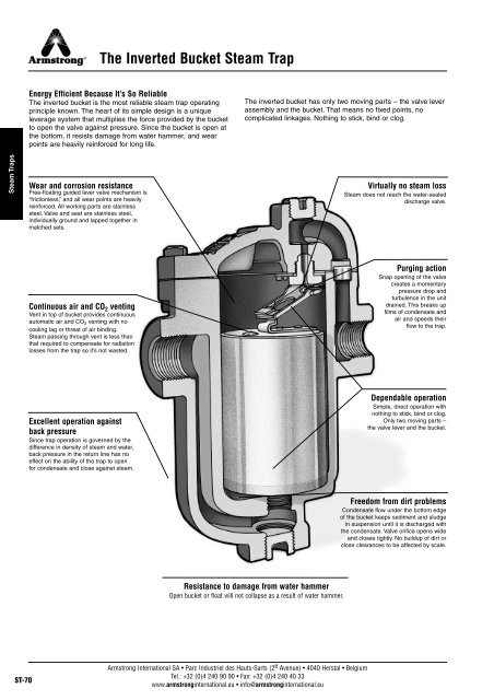
The Inverted Bucket Steam Trap
The Inverted Bucket Steam Trap
The Inverted Bucket Steam Trap

Create successful ePaper yourself
Turn your PDF publications into a flip-book with our unique Google optimized e-Paper software.
<strong>The</strong> <strong>Inverted</strong> <strong>Bucket</strong> <strong>Steam</strong> <strong>Trap</strong><br />
<strong>Steam</strong> <strong>Trap</strong>s<br />
Energy Efficient Because It’s So Reliable<br />
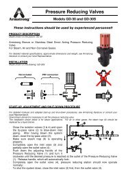
<strong>The</strong> inverted bucket is the most reliable steam trap operating<br />
principle known. <strong>The</strong> heart of its simple design is a unique<br />
leverage system that multiplies the force provided by the bucket<br />
to open the valve against pressure. Since the bucket is open at<br />
the bottom, it resists damage from water hammer, and wear<br />
points are heavily reinforced for long life.<br />
Wear and corrosion resistance<br />
Free-floating guided lever valve mechanism is<br />
“frictionless,” and all wear points are heavily<br />
reinforced. All working parts are stainless<br />
steel. Valve and seat are stainless steel,<br />
individually ground and lapped together in<br />
matched sets.<br />
<strong>The</strong> inverted bucket has only two moving parts – the valve lever<br />
assembly and the bucket. That means no fixed points, no<br />
complicated linkages. Nothing to stick, bind or clog.<br />
Virtually no steam loss<br />
<strong>Steam</strong> does not reach the water-sealed<br />
discharge valve.<br />
Continuous air and CO 2 venting<br />
Vent in top of bucket provides continuous<br />
automatic air and CO 2 venting with no<br />
cooling lag or threat of air binding.<br />
<strong>Steam</strong> passing through vent is less than<br />
that required to compensate for radiation<br />
losses from the trap so it’s not wasted.<br />
Purging action<br />
Snap opening of the valve<br />
creates a momentary<br />
pressure drop and<br />
turbulence in the unit<br />
drained. This breaks up<br />
films of condensate and<br />
air and speeds their<br />
flow to the trap.<br />
Excellent operation against<br />
back pressure<br />
Since trap operation is governed by the<br />
difference in density of steam and water,<br />
back pressure in the return line has no<br />
effect on the ability of the trap to open<br />
for condensate and close against steam.<br />
Dependable operation<br />
Simple, direct operation with<br />
nothing to stick, bind or clog.<br />
Only two moving parts –<br />
the valve lever and the bucket.<br />
Freedom from dirt problems<br />
Condensate flow under the bottom edge<br />
of the bucket keeps sediment and sludge<br />
in suspension until it is discharged with<br />
the condensate. Valve orifice opens wide<br />
and closes tightly. No buildup of dirt or<br />
close clearances to be affected by scale.<br />
Resistance to damage from water hammer<br />
Open bucket or float will not collapse as a result of water hammer.<br />
ST-70<br />
Armstrong International SA • Parc Industriel des Hauts-Sarts (2 e Avenue) • 4040 Herstal • Belgium<br />
Tel.: +32 (0)4 240 90 90 • Fax: +32 (0)4 240 40 33<br />
www.armstronginternational.eu • info@armstronginternational.eu
<strong>Inverted</strong> <strong>Bucket</strong> <strong>Steam</strong> <strong>Trap</strong><br />
Conserves Energy Even in the Presence of Wear<br />
Armstrong inverted bucket steam traps open and close based<br />
on the difference in density between condensate and steam –<br />
the inverted bucket principle. <strong>The</strong>y open and close gently,<br />
minimizing wear. This simple fact means that inverted buckets<br />
are subject to less wear than some other types of traps.<br />
In fact, as an Armstrong inverted bucket trap wears, its tight<br />
seal actually improves. <strong>The</strong> ball valve and seat of the Armstrong<br />
trap provide essentially line contact – resulting in a tight seal<br />
because the entire closing force is concentrated on one narrow<br />
seating ring.<br />
An Armstrong inverted bucket trap continues to operate<br />
efficiently with use. Gradual wear slightly increases the diameter<br />
of the seat and alters the shape and diameter of the ball valve.<br />
But, as this occurs, a tight seal is still preserved – the ball<br />
merely seats itself deeper.<br />
Corrosion-Resistant Parts<br />
<strong>The</strong> stainless steel valve and seat of the Armstrong inverted<br />
bucket steam trap are individually ground and lapped together<br />
in matched sets. All other working parts are wear- and<br />
corrosion-resistant stainless steel.<br />
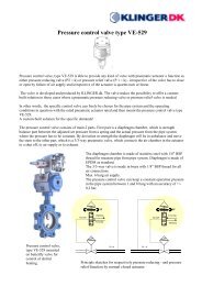
Armstrong IB Valve Seating/Ball Valve<br />
Venting of Air and CO 2<br />
<strong>The</strong> Armstrong inverted bucket provides continuous automatic<br />
air and CO 2 venting with no cooling lag or threat of air binding.<br />
Operation Against Back Pressure<br />
<strong>The</strong> Armstrong inverted bucket has excellent performance<br />
against back pressure. It has no adverse effect on inverted<br />
bucket operation other than to reduce its capacity by the low<br />
differential. <strong>The</strong> bucket simply requires less force to pull the<br />
valve open and cycle the trap.<br />
Freedom From Dirt Problems<br />
Armstrong designed its inverted bucket to be virtually free of dirt<br />
problems. <strong>The</strong> valve and seat are at the top of the trap, far away<br />
from the larger particles of dirt, which fall to the bottom. Here<br />
the up-and-down action of the bucket pulverizes them. Since the<br />
valve of an inverted bucket is either fully closed or open, dirt<br />
particles pass freely. And the swift flow of condensate from<br />
under the bucket’s edge creates a unique self-scrubbing action<br />
that sweeps dirt out of the trap.<br />
IB Valve Wear Characteristics<br />
<strong>Steam</strong> <strong>Trap</strong>s<br />
Line Contact – Single Seat<br />
Infinite Number of Center Lines<br />
and Seating Circumferences<br />
Armstrong IB ball valve continues to seat itself deeper,<br />
providing a tight seal even in the presence of wear.<br />
All dimensions and weights are approximate. Use certified print for exact dimensions. Design and materials are subject to change without notice.<br />
Armstrong International SA • Parc Industriel des Hauts-Sarts (2 e Avenue) • 4040 Herstal • Belgium<br />
Tel.: +32 (0)4 240 90 90 • Fax: +32 (0)4 240 40 33<br />
www.armstronginternational.eu • info@armstronginternational.eu<br />
ST-71
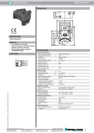
IB <strong>Steam</strong> <strong>Trap</strong> Summary Capacity Chart<br />
Pressure difference in bar between steam line and return line with trap valve closed<br />
Note: Above capacity chart does not include all models available. Refer to specific page of trap required for capacities not covered above.<br />
200, 800 and 880 Series 300 Series 400 Series 5000 Series<br />
<strong>Steam</strong> <strong>Trap</strong>s<br />
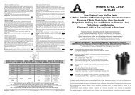
Models 216, 816,<br />
316, 416<br />
Models 215, 815,<br />
315, 415, 5155<br />
Models 214, 814,<br />
314, 5133<br />
Models 213, 813,<br />
883, 313, 983, 413<br />
Models 312<br />
Models 212, 812,<br />
882<br />
Models 211, 811,<br />
881, 310, 411, 421<br />
Models 800, 880<br />
Pressure difference in bar between steam line and return line with trap valve closed<br />
Note: Above capacity chart does not include all models available. Refer to specific page of trap required for capacities not covered above.<br />
ST-72<br />
Armstrong International SA • Parc Industriel des Hauts-Sarts (2 e Avenue) • 4040 Herstal • Belgium<br />
Tel.: +32 (0)4 240 90 90 • Fax: +32 (0)4 240 40 33<br />
www.armstronginternational.eu • info@armstronginternational.eu
How to Use the IB <strong>Steam</strong> <strong>Trap</strong> Summary Capacity Chart<br />
How the Capacity Chart was made<br />
<strong>The</strong> Armstrong capacity chart shows continuous discharge<br />
capacities of Armstrong traps under actual operating conditions<br />
as determined by literally hundreds of tests. In these tests<br />
condensate at the steam temperature corresponding to the test<br />
pressure was used. <strong>The</strong> choking effect of flash steam through<br />
the orifice, as well as the back pressure created by flash steam,<br />
were automatically taken into account. Actual installation<br />
hookups were used so that pipe friction in both inlet and<br />
discharge lines also were reflected in the results.<br />
<strong>Trap</strong> capacity ratings based on cold water tests which produce<br />
no flash steam would be much too high. Orifice tests also are<br />
too high because they ignore pipe friction. <strong>The</strong>oretical<br />
calculations of trap capacities have never been conservative.<br />
You can rely on Armstrong capacity ratings because they show<br />
actual capacities of hot condensate.<br />
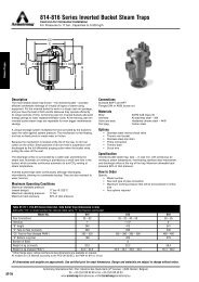
Heavy “sawtooth” curves<br />
show capacities for traps using maximum possible diameter<br />
orifices for the pressures shown.<br />
Thin line curves<br />
extending down to the left of the heavy curves show the<br />
capacities of Armstrong traps at pressures below their<br />
maximum ratings. For example: a model 216 trap with 1/2"<br />
orifice good for a maximum working pressure of 8,5 bar will<br />
have a continuous discharge capacity of a little less than 6 000<br />
kg/h at 2,8 bar.<br />
How to use the inverted bucket trap capacity chart<br />
To select an inverted bucket steam trap using the Armstrong<br />
capacity chart, you must know the condensate load, safety<br />
factor and pressure differential. Remember, the objective is<br />
always to select a trap that can 1) operate at the maximum<br />
differential pressure and 2) handle the capacity at the minimum<br />
differential pressure. Consider the following typical problems:<br />
Example 1:<br />
Constant Pressure and Condensing Rate<br />
Given:<br />
Maximum pressure differential: 5 bar<br />
Operating differential: 4 bar<br />
Condensate load:<br />
133 kg/h<br />
times 3:1 safety factor or: 400 kg/h<br />
Enter chart at 4 bar and go up to 400 kg/h capacity. This is<br />
directly on the 5/32" orifice line as shown in Chart ST-73-1. <strong>The</strong><br />
capacity of this 5/32" orifice at pressures less than 2 bar is<br />
indicated by the thin line. Follow the line to the right to the<br />
vertical drop at 5 bar. This means this orifice will operate to a<br />
maximum of 5 bar differential - the other requirement for this<br />
application. Follow the heavy line back to the left and note that<br />
it's attached to the arrow indicating that the 211, 811 or 881<br />
traps (1811 and 1011 are other possibilities) with the 5/32"<br />
orifice will yield this capacity. This is the trap to use.<br />
Example 2:<br />
Constant Pressure and Condensing Rate but with Possible<br />
High Back Pressure<br />
Assume for example:<br />
Maximum pressure differential: 6 bar<br />
Operating differential minimum: 3 bar<br />
Operating differential normally: 4 bar<br />
Condensate load:<br />
133 kg/h<br />
times 3:1 safety factor or: 400 kg/h<br />
To solve the problem, refer to the sawtooth chart, page ST-72.<br />
Enter at the minimum differential pressure (3 bar) and move up<br />
until you intersect a line that is above 400 kg/h capacity, which<br />
is the first thin line above the heavy “sawtooth” for the 211, 811<br />
and 881 traps. Note that this is the continuation of the capacity<br />
line for the 5/32" orifice for the 212, 812 and 882 traps. Now<br />
follow the line to the right until the vertical drop at 8,5 bar<br />
differential. This is within our requirement of 6 bar. <strong>The</strong>refore a<br />
5/32" orifice can handle the 400 kg/h condensate load when<br />
fitted into a 212, 812 or 882 trap and that it will not lock shut at<br />
the 6 bar maximum differential. This is the trap to use since it<br />
will handle the load at both the minimum and maximum<br />
operating differentials, even though it has a maximum operating<br />
pressure differential of 8,5 bar.<br />
Orifice sizes:<br />
1 7/8" = 47,0 mm 5/16" = 7,9 mm<br />
1 5/8" = 41,0 mm 19/64" = 7,5 mm<br />
1 17/32" = 39,0 mm 9/32" = 7,1 mm<br />
1 1/8" = 28,0 mm 17/64" = 6,7 mm<br />
1 1/16" = 27,0 mm 1/4" = 6,4 mm<br />
7/8" = 22,2 mm 7/32" = 5,6 mm<br />
3/4" = 19,0 mm 13/64" = 5,1 mm<br />
11/16" = 17,5 mm 3/16" = 4,8 mm<br />
5/8" = 15,9 mm 11/64" = 4,4 mm<br />
9/16" = 14,3 mm 5/32" = 4,0 mm<br />
1/2" = 12,7 mm 1/8" = 3,2 mm<br />
7/16" = 11,2 mm 7/64" = 2,8 mm<br />
3/8" = 9,5 mm # 38 = 2,5 mm<br />
11/32" = 8,7 mm 5/64" = 2,0 mm<br />
Chart ST-73-1: Selection Curve Example 1<br />
Capacity in kg/h<br />
Models 211, 811,<br />
881<br />
Pressure Differential in bar<br />
<strong>Steam</strong> <strong>Trap</strong>s<br />
Armstrong International SA • Parc Industriel des Hauts-Sarts (2 e Avenue) • 4040 Herstal • Belgium<br />
Tel.: +32 (0)4 240 90 90 • Fax: +32 (0)4 240 40 33<br />
www.armstronginternational.eu • info@armstronginternational.eu<br />
ST-73
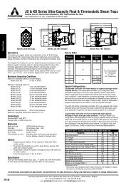
200 Series <strong>Inverted</strong> <strong>Bucket</strong> <strong>Steam</strong> <strong>Trap</strong>s<br />
Cast Iron for Vertical Installation<br />
For Pressures to 17 bar...Capacities to 9 000 kg/h<br />
A<br />
<strong>Steam</strong> <strong>Trap</strong>s<br />
B<br />
BB<br />
Description<br />
<strong>The</strong> most reliable steam trap known – the inverted bucket – provides<br />
efficient condensate drainage of virtually all types of steam-using<br />
equipment. Put the inverted bucket to work in a tough cast iron package,<br />
and you have the best of both worlds. Because they operate efficiently<br />
for longer periods of time, Armstrong cast iron inverted buckets add solid<br />
energy savings to lower replacement/labor costs.<br />
A unique leverage system multiplies the force provided by the bucket to<br />
open the valve against system pressure. <strong>The</strong> mechanism is free-floating,<br />
and has no fixed pivots to create wear or friction.<br />
Because the mechanism is located at the top of the trap, no dirt can<br />
collect on the orifice. Small particles of dirt are held in suspension until<br />
discharged by the full differential purging action when the bucket sinks,<br />
pulling the valve off the seat.<br />
<strong>The</strong> discharge orifice is surrounded by a water seal, preventing live<br />
steam loss. Automatic air venting is provided by a small vent hole in the<br />
bucket, which provides continuous automatic air and CO 2 venting at<br />
steam temperature.<br />
<strong>Inverted</strong> bucket traps drain continuously, although discharging<br />
intermittently, allowing no condensate backup. <strong>The</strong>y are also resistant to<br />
water hammer.<br />
Maximum Operating Conditions<br />
Maximum allowable pressure<br />
(vessel design): 17 bar @ 232°C<br />
Maximum operating pressure: 17 bar<br />
Maximum back pressure: 99% of inlet pressure<br />
Connections<br />
Screwed BSPT and NPT<br />
Flanged DIN or ANSI (screw on)<br />
Materials<br />
Body: ASTM A48 Class 30<br />
Cap: ASTM A48 Class 30<br />
ASTM A-105 (Only 215 if PMO > 9 bar)<br />
Internals: All stainless steel – 304<br />
Valve and seat:<br />
Hardened chrome steel – 440F<br />
Test plug:<br />
Carbon steel<br />
Options<br />
• Stainless steel internal check valve<br />
• <strong>The</strong>rmic vent bucket<br />
• Scrub wire<br />
Specification<br />
<strong>Inverted</strong> bucket steam trap, type ... in cast iron, with continuous air<br />
venting at steam temperature, free floating stainless steel mechanism,<br />
and discharge orifice at the top of the trap. Maximum allowable back<br />
pressure 99% of inlet pressure.<br />
How to Order<br />
Specify:<br />
• Model number<br />
• Size and type of pipe connection<br />
• Maximum working pressure that will be encountered or orifice<br />
size<br />
• Any options required<br />
Table ST-74-1. 200 Series, Bottom Inlet, Top Outlet <strong>Trap</strong> (dimensions in mm)<br />
Add suffix “CV” to model number for internal check valve, “T” for thermic vent bucket.<br />
Model No. 211 212 213 214 215 216<br />
Pipe Connections 15 15 – 20 15 – 20 – 25 25 – 32 25 – 32 – 40 40 – 50<br />
Test plug 1/8" 3/8" 1/2" 1/2" 3/4" 1"<br />
“A” Flange Diameter 108 133 162 190 216 259<br />
“B” Face-to-Face (screwed) 162 203 273 317 364 432<br />
“BB” Face-to-Face (flanged PN40*) 282 320 - 330 390 - 400 - 392 436 - 440 484 - 494 - 494 562 - 568<br />
Number of Bolts 6 8 6 8 8 12<br />
Weight in kg (screwed) 2,7 5,2 9,2 15,0 20,3 35,2<br />
Weight in kg (flanged PN40*) 4,1 7,0 – 7,6 11 – 11,6 – 12 18,6 – 20,2 21 – 22,7 – 23 39,6 – 41,2<br />
* Other flange sizes, ratings and face-to-face dimensions are available on request.<br />
Shade indicates products that are CE Marked according to the PED (97/23/EC). All the other models comply with the Article 3.3 of the same directive.<br />
All dimensions and weights are approximate. Use certified print for exact dimensions. Design and materials are subject to change without notice.<br />
ST-74<br />
Armstrong International SA • Parc Industriel des Hauts-Sarts (2 e Avenue) • 4040 Herstal • Belgium<br />
Tel.: +32 (0)4 240 90 90 • Fax: +32 (0)4 240 40 33<br />
www.armstronginternational.eu • info@armstronginternational.eu
200 Series <strong>Inverted</strong> <strong>Bucket</strong> <strong>Steam</strong> <strong>Trap</strong>s<br />
Cast Iron for Vertical Installation<br />
For Pressures to 17 bar...Capacities to 9 000 kg/h<br />
Table ST-75-1. Model 211 Capacity<br />
Table ST-75-2. Model 212 Capacity<br />
1<br />
2<br />
1 2 5<br />
8,5<br />
14<br />
5 8,5<br />
14<br />
17<br />
17<br />
Capacity, kg/h<br />
Capacity, kg/h<br />
<strong>Steam</strong> <strong>Trap</strong>s<br />
Pressure, bar<br />
Pressure, bar<br />
Table ST-75-3. Model 213 Capacity<br />
Table ST-75-4. Model 214 Capacity<br />
1<br />
2<br />
4<br />
5,5 8,5 12,5<br />
17<br />
1 2 4 5,5<br />
8,5<br />
12,5<br />
17<br />
Capacity, kg/h<br />
Capacity, kg/h<br />
Pressure, bar<br />
Pressure, bar<br />
Table ST-75-5. Model 215 Capacity<br />
Table ST-75-6. Model 216 Capacity<br />
1 2 4<br />
7 9 12,5<br />
15,5<br />
1 1,7 3 4 5,5 8,5 12,5 17<br />
17<br />
Capacity, kg/h<br />
Capacity, kg/h<br />
Pressure, bar<br />
Pressure, bar<br />
All dimensions and weights are approximate. Use certified print for exact dimensions. Design and materials are subject to change without notice.<br />
Armstrong International SA • Parc Industriel des Hauts-Sarts (2 e Avenue) • 4040 Herstal • Belgium<br />
Tel.: +32 (0)4 240 90 90 • Fax: +32 (0)4 240 40 33<br />
www.armstronginternational.eu • info@armstronginternational.eu<br />
ST-75
800-813 Series <strong>Inverted</strong> <strong>Bucket</strong> <strong>Steam</strong> <strong>Trap</strong>s<br />
Cast Iron for Horizontal Installation<br />
For Pressures to 17 bar...Capacities to 2 000 kg/h<br />
<strong>Steam</strong> <strong>Trap</strong>s<br />
Description<br />
<strong>The</strong> most reliable steam trap known – the inverted bucket – provides<br />
efficient condensate drainage of virtually all types of steam-using<br />
equipment. Put the inverted bucket to work in a tough cast iron package,<br />
and you have the best of both worlds. Because they operate efficiently<br />
for longer periods of time, Armstrong cast iron inverted buckets add solid<br />
energy savings to lower replacement/labor costs. All Armstrong cast iron<br />
inverted bucket steam traps are repairable for even bigger maintenance<br />
savings.<br />
A unique leverage system multiplies the force provided by the bucket to<br />
open the valve against system pressure. <strong>The</strong> mechanism is free-floating,<br />
and has no fixed pivots to create wear or friction.<br />
Because the mechanism is located at the top of the trap, no dirt can<br />
collect on the orifice. Small particles of dirt are held in suspension until<br />
discharged by the full differential purging action when the bucket sinks,<br />
pulling the valve off the seat.<br />
<strong>The</strong> discharge orifice is surrounded by a water seal, preventing live<br />
steam loss. Automatic air venting is provided by a small vent hole in the<br />
bucket, which provides continuous automatic air and CO 2 venting at<br />
steam temperature.<br />
<strong>Inverted</strong> bucket traps drain continuously, although discharging<br />
intermittently, allowing no condensate backup. <strong>The</strong>y are also resistant to<br />
water hammer.<br />
Maximum Operating Conditions<br />
Maximum allowable pressure<br />
(vessel design): 17 bar @ 232°C<br />
Maximum operating pressure: Model 800: 10 bar<br />
Model 811-813: 17 bar<br />
Maximum back pressure: 99% of inlet pressure<br />
Connections<br />
Screwed BSPT and NPT<br />
Flanged DIN or ANSI (screw on)<br />
Materials<br />
Body: ASTM A48 Class 30<br />
Internals: All stainless steel – 304<br />
Valve and seat:<br />
Hardened chrome steel – 440F<br />
Test plug:<br />
Carbon steel<br />
Options<br />
• Stainless steel internal check valve<br />
• <strong>The</strong>rmic vent bucket<br />
• Stainless steel pop drain<br />
• Probe connection<br />
• <strong>The</strong>rmo drain<br />
• Scrub wire<br />
Specification<br />
<strong>Inverted</strong> bucket steam trap, type ... in cast iron, with continuous air<br />
venting at steam temperature, free-floating stainless steel mechanism,<br />
and discharge orifice at the top of the trap. Maximum allowable back<br />
pressure 99% of inlet pressure.<br />
How to Order<br />
Specify:<br />
• Model number<br />
• Size and type of pipe connection<br />
• Maximum working pressure that will be encountered or orifice<br />
size<br />
• Any options required<br />
Table ST-76-1. 800-813 Series Side Inlet, Side Outlet <strong>Trap</strong> (dimensions in mm)<br />
Add suffix “CV” to model number for internal check valve, “T” for thermic vent bucket.<br />
Model No. 800* 811 812 813<br />
Pipe Connections 15 – 20 15 – 20 – 25 15 – 20 20 – 25<br />
Test plug 1/4" 1/4" 1/2" 3/4"<br />
“B” Height 138 175 230 298<br />
“C” Face-to-Face (screwed) 127 127 – 127 – 133 165 197<br />
“CC” Face-to-Face (flanged PN40**) 195 – 191 195 – 191 – 197 233 – 229 261<br />
“D” Bottom to C L Inlet 70 108 137 179<br />
Number of Bolts 6<br />
Weight in kg (screwed) 2,3 2,7 6,8 12,5<br />
Weight in kg (flanged PN40**) 3,6 – 4,3 4,1 – 4,3 – 4,8 8,2 – 9,0 14,3 – 14,8<br />
* Cannot be furnished with both thermic vent bucket and check valve.<br />
** Other flange sizes, ratings and face-to-face dimensions are available on request.<br />
All models comply with the article 3.3 of the PED (97/23/EC).<br />
All dimensions and weights are approximate. Use certified print for exact dimensions. Design and materials are subject to change without notice.<br />
ST-76<br />
Armstrong International SA • Parc Industriel des Hauts-Sarts (2 e Avenue) • 4040 Herstal • Belgium<br />
Tel.: +32 (0)4 240 90 90 • Fax: +32 (0)4 240 40 33<br />
www.armstronginternational.eu • info@armstronginternational.eu
800-813 Series <strong>Inverted</strong> <strong>Bucket</strong> <strong>Steam</strong> <strong>Trap</strong>s<br />
Cast Iron for Horizontal Installation<br />
For Pressures to 17 bar...Capacities to 2 000 kg/h<br />
Table ST-77-1. Model 800 Capacity<br />
Table ST-77-2. Model 811 Capacity<br />
1,4 5,5 8,5<br />
1<br />
2<br />
10,5<br />
5 8,5<br />
14<br />
17<br />
Capacity, kg/h<br />
Capacity, kg/h<br />
<strong>Steam</strong> <strong>Trap</strong>s<br />
Pressure, bar<br />
Pressure, bar<br />
Table ST-77-3. Model 812 Capacity<br />
Table ST-77-4. Model 813 Capacity<br />
1 2 5<br />
8,5<br />
14<br />
1<br />
2<br />
4<br />
5,5 8,5 12,5<br />
17<br />
17<br />
Capacity, kg/h<br />
Capacity, kg/h<br />
Pressure, bar<br />
Pressure, bar<br />
All dimensions and weights are approximate. Use certified print for exact dimensions. Design and materials are subject to change without notice.<br />
Armstrong International SA • Parc Industriel des Hauts-Sarts (2 e Avenue) • 4040 Herstal • Belgium<br />
Tel.: +32 (0)4 240 90 90 • Fax: +32 (0)4 240 40 33<br />
www.armstronginternational.eu • info@armstronginternational.eu<br />
ST-77
814-816 Series <strong>Inverted</strong> <strong>Bucket</strong> <strong>Steam</strong> <strong>Trap</strong>s<br />
Cast Iron for Horizontal Installation<br />
For Pressures to 17 bar...Capacities to 9 000 kg/h<br />
CC<br />
C<br />
<strong>Steam</strong> <strong>Trap</strong>s<br />
D<br />
B<br />
Description<br />
<strong>The</strong> most reliable steam trap known – the inverted bucket – provides<br />
efficient condensate drainage of virtually all types of steam-using<br />
equipment. Put the inverted bucket to work in a tough cast iron package,<br />
and you have the best of both worlds. Because they operate efficiently<br />
for longer periods of time, Armstrong cast iron inverted buckets add solid<br />
energy savings to lower replacement/labor costs. All Armstrong cast iron<br />
inverted bucket steam traps are repairable for even bigger maintenance<br />
savings.<br />
A unique leverage system multiplies the force provided by the bucket to<br />
open the valve against system pressure. <strong>The</strong> mechanism is free-floating,<br />
and has no fixed pivots to create wear or friction.<br />
Because the mechanism is located at the top of the trap, no dirt can<br />
collect on the orifice. Small particles of dirt are held in suspension until<br />
discharged by the full differential purging action when the bucket sinks,<br />
pulling the valve off the seat.<br />
<strong>The</strong> discharge orifice is surrounded by a water seal, preventing live<br />
steam loss. Automatic air venting is provided by a small vent hole in the<br />
bucket, which provides continuous automatic air and CO 2 venting at<br />
steam temperature.<br />
<strong>Inverted</strong> bucket traps drain continuously, although discharging<br />
intermittently, allowing no condensate backup. <strong>The</strong>y are also resistant to<br />
water hammer.<br />
Maximum Operating Conditions<br />
Maximum allowable pressure<br />
(vessel design): 17 bar @ 232°C<br />
Maximum operating pressure: 17 bar<br />
Maximum back pressure: 99% of inlet pressure<br />
Connections<br />
Screwed BSPT and NPT<br />
Flanged DIN or ANSI (screw on)<br />
Materials<br />
Body: ASTM A48 Class 30<br />
Internals: All stainless steel – 304<br />
Valve and seat:<br />
Hardened chrome steel – 440F<br />
Test plug:<br />
Carbon steel<br />
Options<br />
• Stainless steel internal check valve<br />
• <strong>The</strong>rmic vent bucket<br />
• Stainless steel pop drain<br />
• Probe connection<br />
• <strong>The</strong>rmo drain<br />
• Scrub wire<br />
Specification<br />
<strong>Inverted</strong> bucket steam trap, type ... in cast iron, with continuous air<br />
venting at steam temperature, free-floating stainless steel mechanism,<br />
and discharge orifice at the top of the trap. Maximum allowable back<br />
pressure 99% of inlet pressure.<br />
How to Order<br />
Specify:<br />
• Model number<br />
• Size and type of pipe connection<br />
• Maximum working pressure that will be encountered or orifice<br />
size<br />
• Any options required<br />
Table ST-78-1. 814-816 Series Side Inlet, Side Outlet <strong>Trap</strong> (dimensions in mm)<br />
Add suffix “CV” to model number for internal check valve, “T” for thermic vent bucket.<br />
Model No. 814 815 816<br />
Pipe Connections 25 – 32 25 – 32 – 40 – 50 50 – 65<br />
Test plug 1" 1 1/2" 2"<br />
“B” Height 346 413 541<br />
“C” Face-to-Face (screwed) 229 260 330<br />
“CC” Face-to-Face (flanged PN40*) 293 – 355 382 – 386 – 392 – 398 468 – 480<br />
“D” Bottom to C L Inlet 198 203 279<br />
Number of Bolts 8<br />
Weight in kg (screwed) 20,0 32,2 59,4<br />
Weight in kg (flanged PN40*) 23,0 – 24,6 34,6 – 36,2 – 36,6 – 38,2 65,4 – 68,2<br />
* Other flange sizes, ratings and face-to-face dimensions are available on request.<br />
All models are CE Marked according to the PED (97/23/EC), but PMA for 816 is 15 bar.<br />
All dimensions and weights are approximate. Use certified print for exact dimensions. Design and materials are subject to change without notice.<br />
ST-78<br />
Armstrong International SA • Parc Industriel des Hauts-Sarts (2 e Avenue) • 4040 Herstal • Belgium<br />
Tel.: +32 (0)4 240 90 90 • Fax: +32 (0)4 240 40 33<br />
www.armstronginternational.eu • info@armstronginternational.eu
814-816 Series <strong>Inverted</strong> <strong>Bucket</strong> <strong>Steam</strong> <strong>Trap</strong>s<br />
Cast Iron for Horizontal Installation<br />
For Pressures to 17 bar...Capacities to 9 000 kg/h<br />
Table ST-79-1. Model 814 Capacity<br />
Table ST-79-2. Model 815 Capacity<br />
Capacity, kg/h<br />
1 2 4 5,5<br />
8,5<br />
12,5<br />
17<br />
Capacity, kg/h<br />
1 2 4<br />
7 9 12,5<br />
15,5<br />
17<br />
<strong>Steam</strong> <strong>Trap</strong>s<br />
Pressure, bar<br />
Pressure, bar<br />
Table ST-79-3. Model 816 Capacity<br />
1 1,7 3 4 5,5 8,5 12,5 17<br />
Capacity, kg/h<br />
Pressure, bar<br />
All dimensions and weights are approximate. Use certified print for exact dimensions. Design and materials are subject to change without notice.<br />
Armstrong International SA • Parc Industriel des Hauts-Sarts (2 e Avenue) • 4040 Herstal • Belgium<br />
Tel.: +32 (0)4 240 90 90 • Fax: +32 (0)4 240 40 33<br />
www.armstronginternational.eu • info@armstronginternational.eu<br />
ST-79
880 Series <strong>Inverted</strong> <strong>Bucket</strong> <strong>Steam</strong> <strong>Trap</strong>s<br />
Cast Iron for Horizontal Installation, with Integral Strainer<br />
For Pressures to 17 bar...Capacities to 2 000 kg/h<br />
CC<br />
C<br />
<strong>Steam</strong> <strong>Trap</strong>s<br />
D<br />
B<br />
E<br />
Description<br />
<strong>The</strong> most reliable steam trap known – he inverted bucket – provides<br />
efficient condensate drainage of virtually all types of steam-using<br />
equipment. Put the inverted bucket to work in a tough cast iron package<br />
with an integral strainer, and you have the best of both worlds. Because<br />
they operate efficiently for longer periods of time, Armstrong cast iron<br />
inverted buckets add solid energy savings to lower replacement/labor<br />
costs. All Armstrong cast iron inverted bucket steam traps are repairable<br />
for even bigger maintenance savings.<br />
A unique leverage system multiplies the force provided by the bucket to<br />
open the valve against system pressure. <strong>The</strong> mechanism is free-floating,<br />
and has no fixed pivots to create wear or friction.<br />
Because the mechanism is located at the top of the trap, no dirt can<br />
collect on the orifice. Small particles of dirt are held in suspension until<br />
discharged by the full differential purging action when the bucket sinks,<br />
pulling the valve off the seat.<br />
<strong>The</strong> discharge orifice is surrounded by a water seal, preventing live<br />
steam loss. Automatic air venting is provided by a small vent hole in the<br />
bucket, which provides continuous automatic air and CO 2 venting at<br />
steam temperature.<br />
<strong>Inverted</strong> bucket traps drain continuously, although discharging<br />
intermittently, allowing no condensate backup. <strong>The</strong>y are also resistant to<br />
water hammer.<br />
Connections<br />
Screwed BSPT and NPT<br />
Flanged DIN or ANSI (screw on, except for model 881F – integral)<br />
Maximum Operating Conditions<br />
Maximum allowable pressure<br />
(vessel design): 17 bar @ 232°C<br />
Maximum operating pressure:<br />
Maximum back pressure:<br />
Table ST-80-1. 880 Series Side Inlet, Side Outlet <strong>Trap</strong> with Integral Strainer (dimensions in mm)<br />
Add suffix “CV” to model number for internal check valve, “T” for thermic vent bucket.<br />
881F: 16 bar @ 120°C (PN16)<br />
Model 880: 10 bar<br />
Model 881 - 883: 17 bar<br />
99% of inlet pressure<br />
Materials<br />
Body: ASTM A48 Class 30<br />
Internals: All stainless steel – 304<br />
Valve and seat:<br />
Hardened chrome steel – 440F<br />
Test plug:<br />
Carbon steel<br />
Strainer: Stainless steel – 304<br />
Options<br />
• Stainless steel internal check valve<br />
• <strong>The</strong>rmic vent bucket<br />
• Scrub wire<br />
Specification<br />
<strong>Inverted</strong> bucket steam trap, type ... in cast iron with integral strainer, with<br />
continuous air venting at steam temperature, with free-floating stainless<br />
steel mechanism, and discharge orifice at the top of the trap. Maximum<br />
allowable back pressure 99% of inlet pressure.<br />
How to Order<br />
Specify:<br />
• Model number<br />
• Size and type of pipe connection<br />
• Maximum working pressure that will be encountered or orifice<br />
size<br />
• Any options required<br />
Model No. 880* 881 - 881F 882 883<br />
Pipe Connections 15 – 20 15 – 20 – 25 15 – 20 20 – 25 – 32<br />
Test plug 1/4" 1/4" 1/2" 3/4"<br />
“B” Height 154 179 244 314<br />
“C” Face-to-Face (screwed) 127 127 165 200<br />
“CC” Face-to-Face (flanged PN40** - 881F PN16) 195 – 191 150 – 150 – 160 233 – 229 264 – 264 – 326<br />
“D” Bottom to C L Inlet 87 113 146 187<br />
“E” Blowdown Connection (883 only) N/A N/A 3/8" 1/2"<br />
Number of Bolts 6<br />
Weight in kg (screwed) 2,5 2,7 7 14,1<br />
Weight in kg (flanged PN40** - 881F PN16) 4,0 – 4,6 3,8 – 4,2 – 4,6 8,8 – 9,4 15,6 – 16,1 – 17,7<br />
* Cannot be furnished with both thermic vent bucket and check valve.<br />
** Other flange sizes, ratings and face-to-face dimensions are available on request.<br />
All models comply with the article 3.3 of the PED (97/23/EC).<br />
All dimensions and weights are approximate. Use certified print for exact dimensions. Design and materials are subject to change without notice.<br />
ST-80<br />
Armstrong International SA • Parc Industriel des Hauts-Sarts (2 e Avenue) • 4040 Herstal • Belgium<br />
Tel.: +32 (0)4 240 90 90 • Fax: +32 (0)4 240 40 33<br />
www.armstronginternational.eu • info@armstronginternational.eu
880 Series <strong>Inverted</strong> <strong>Bucket</strong> <strong>Steam</strong> <strong>Trap</strong>s<br />
Cast Iron for Horizontal Installation, with Integral Strainer<br />
For Pressures to 17 bar...Capacities to 2 000 kg/h<br />
Table ST-81-1. Model 880 Capacity<br />
Table ST-81-2. Model 881 Capacity<br />
1,4 5,5 8,5<br />
1<br />
2<br />
10,5<br />
5 8,5<br />
14<br />
17<br />
Capacity, kg/h<br />
Capacity, kg/h<br />
<strong>Steam</strong> <strong>Trap</strong>s<br />
Pressure, bar<br />
Pressure, bar<br />
Table ST-81-3. Model 882 Capacity<br />
Table ST-81-4. Model 883 Capacity<br />
1 2 5<br />
8,5<br />
14<br />
1<br />
2<br />
4<br />
5,5 8,5 12,5<br />
17<br />
17<br />
Capacity, kg/h<br />
Capacity, kg/h<br />
Pressure, bar<br />
Pressure, bar<br />
All dimensions and weights are approximate. Use certified print for exact dimensions. Design and materials are subject to change without notice.<br />
Armstrong International SA • Parc Industriel des Hauts-Sarts (2 e Avenue) • 4040 Herstal • Belgium<br />
Tel.: +32 (0)4 240 90 90 • Fax: +32 (0)4 240 40 33<br />
www.armstronginternational.eu • info@armstronginternational.eu<br />
ST-81
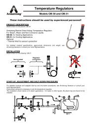
TVS-800 Series Cast Iron <strong>Trap</strong> Valve Station<br />
Put the principle of the inverted bucket to work in a tough cast<br />
iron package and you have the best of both worlds – energy<br />
efficiency and long-lasting reliability. Add the advantages of<br />
valves integrated into one compact trap/valve casting, and you<br />
extend the benefits into installation, trap testing and<br />
maintenance.<br />
All the components are concentrated in a single, accessible<br />
package and can be dealt with in-line. And if you have existing<br />
Armstrong cast iron traps in-line, identical face-to-face<br />
dimensions will make retrofitting with a new, patented*<br />
Armstrong <strong>Trap</strong> Valve Station (TVS) a snap. You’ll also reduce<br />
your inventory requirements. So you’ll eliminate what you’re<br />
paying just to keep parts on hand.<br />
<strong>Steam</strong> <strong>Trap</strong>s<br />
Integral isolation valves<br />
Rugged cast iron package<br />
Reduced costs<br />
TVS saves on these fronts: energy, installation and<br />
maintenance.<br />
Integration of trap and valves<br />
<strong>Inverted</strong> bucket long life and energy efficiency, plus the<br />
savings and convenience of components merged into one<br />
space-saving package.<br />
A full range of options<br />
TVS will accommodate a test valve, strainer, internal<br />
check valve, thermic vent bucket, <strong>Trap</strong>Alert and<br />
<strong>Steam</strong>Eye – remote steam trap monitoring system for<br />
steam traps.<br />
Easy, in-line repairability<br />
Elimination of potential leak points<br />
Reduced design time<br />
Permits combining products with exact face-to-face<br />
dimensions.<br />
Energy-efficient<br />
inverted bucket<br />
steam trap<br />
Optional integral strainer<br />
*U.S. Patent 5 947 145<br />
ST-82<br />
Armstrong International SA • Parc Industriel des Hauts-Sarts (2 e Avenue) • 4040 Herstal • Belgium<br />
Tel.: +32 (0)4 240 90 90 • Fax: +32 (0)4 240 40 33<br />
www.armstronginternational.eu • info@armstronginternational.eu
TVS-800 Series Cast Iron <strong>Trap</strong> Valve Station<br />
TVS makes a long story…short.<br />
Typical Installation<br />
<strong>Trap</strong> Valve Station<br />
<strong>Steam</strong> <strong>Trap</strong>s<br />
<strong>Inverted</strong> bucket trap with two isolation valves<br />
<strong>Inverted</strong> bucket trap with two isolation valves, strainer<br />
<strong>Inverted</strong> bucket trap with two isolation valves,<br />
strainer and check valve<br />
<strong>The</strong> Innovation Is Integration<br />
<strong>The</strong> Armstrong TVS makes what used to be long, complicated<br />
steam installation stories simple and compact. It shortens<br />
installations by integrating components – specifically an inverted<br />
bucket steam trap with two or more valves.<br />
For example, here’s an old description for a typical installation:<br />
valve-nipple-strainer-nipple-trap-nipple-valve. It’s a long tale,<br />
even for this simple piping arrangement. <strong>The</strong> <strong>Trap</strong> Valve Station<br />
rewrites this steam story: pipe-TVS-pipe. In other words, the<br />
TVS makes it all one, delivering the functions of multiple<br />
components in a dramatically smaller unit. It integrates two<br />
high-value products in a package of revolutionary versatility.<br />
Look above to see how the Armstrong cast iron <strong>Trap</strong> Valve<br />
Station has rewritten these typical steam installations.<br />
Average Service Life for Different <strong>Trap</strong> Types 14 bar <strong>Steam</strong> Pressure<br />
<strong>The</strong>rmodynamic disc<br />
Float and thermostatic<br />
<strong>Inverted</strong> bucket<br />
Balanced pressure thermostatic<br />
Bimetallic thermostatic<br />
Above data from “ICI Engineer” January 1993 special issue<br />
with permission from ICI Engineering.<br />
Armstrong International SA • Parc Industriel des Hauts-Sarts (2 e Avenue) • 4040 Herstal • Belgium<br />
Tel.: +32 (0)4 240 90 90 • Fax: +32 (0)4 240 40 33<br />
www.armstronginternational.eu • info@armstronginternational.eu<br />
ST-83
TVS-800 Series <strong>Trap</strong> Valve Stations<br />
Cast Iron for Horizontal Installation, with Integral Piston Valves<br />
For Pressures to 17 bar...Capacities to 2 000 kg/h<br />
CC<br />
CC<br />
<strong>Steam</strong> <strong>Trap</strong>s<br />
D<br />
B<br />
D<br />
B<br />
Model TVS-811 Series TVS-812/813 Series TVS-811/812/813 - Top View<br />
Same principle. Different package. Now the energy-saving performance<br />
and reliability of the inverted bucket steam trap are available in a<br />
versatile new package.<br />
You’ll still enjoy all the familiar benefits. And the same efficient<br />
condensate drainage from virtually every kind of steam-using<br />
equipment. But what you’ll find new are all the benefits of a piston valve<br />
integrated into the same space-saving package.<br />
Maximum Operating Conditions<br />
Maximum allowable pressure<br />
(vessel design): 17 bar @ 232°C<br />
Maximum operating pressure: 17 bar<br />
Maximum back pressure: 99% of inlet pressure<br />
Connections<br />
Screwed BSPT and NPT<br />
Flanged DIN or ANSI (screw on)<br />
Materials<br />
Cap and Body: ASTM A48 Class 30<br />
Internals: All stainless steel – 304<br />
Valve and seat:<br />
Hardened chrome steel – 440F<br />
Piston Valve Handle :<br />
Cast Iron ASTM A47<br />
Internals:<br />
Stainless Steel<br />
Valve Sealing Rings:<br />
Graphite and Stainless Steel<br />
Blowdown valve:<br />
Stainless Steel<br />
Options<br />
• Stainless steel internal check valve<br />
• <strong>The</strong>rmic vent bucket<br />
• Stainless steel pop drain<br />
• Integral strainer<br />
• Scrub wire<br />
• Probe connection<br />
• Blowdown valve (TVS-811 and TVS-812 only)<br />
Specification<br />
<strong>Inverted</strong> bucket steam trap, type ... in cast iron, with continuous air<br />
venting at steam temperature, free-floating stainless steel mechanism,<br />
and discharge orifice at the top of the trap. Integral upstream and<br />
downstream shutoff piston style valves in same dimensional space as<br />
standard bucket trap. Maximum allowable back pressure 99% of inlet<br />
pressure.<br />
How to Order<br />
Specify:<br />
• Model number<br />
• Size and type of pipe connection<br />
• Maximum working pressure that will be encountered or orifice<br />
size<br />
• Any options required<br />
Table ST-84-1. TVS-800 Series <strong>Trap</strong> Valve Station (dimensions in mm)<br />
Model No. TVS-811 TVS-812 TVS-813<br />
Pipe Connections 15 – 20 15 – 20 20 – 25<br />
Test Plug 1/4" 1/2" 3/4"<br />
“A” Width Across Handwheels 197 349 384<br />
“B” Height Valve Open 254 298 362<br />
“C” Face-to-Face (screwed) 127 165 197<br />
“CC” Face-to-Face (flanged PN40*) 247 – 257 285 – 295 327 – 359<br />
“D” Bottom to C L Inlet 94 121 184<br />
“E” Width 179 330 365<br />
“F” 68 114 124<br />
Number of Bolts 6 6 6<br />
Weight in kg (screwed) 5,4 11,3 24,0<br />
Weight in kg (flanged PN40*) 6,8 – 7,0 12,7 – 13,5 25,8 – 26,3<br />
* Other flange sizes, ratings and face-to-face dimensions are available on request.<br />
All models comply with the article 3.3 of the PED (97/23/EC).<br />
All dimensions and weights are approximate. Use certified print for exact dimensions. Design and materials are subject to change without notice.<br />
ST-84<br />
Armstrong International SA • Parc Industriel des Hauts-Sarts (2 e Avenue) • 4040 Herstal • Belgium<br />
Tel.: +32 (0)4 240 90 90 • Fax: +32 (0)4 240 40 33<br />
www.armstronginternational.eu • info@armstronginternational.eu
TVS-800 Series <strong>Trap</strong> Valve Stations<br />
Cast Iron for Horizontal Installation, with Integral Piston Valves<br />
For Pressures to 17 bar...Capacities to 2 000 kg/h<br />
Table ST-85-1. Model TVS-811 Capacity<br />
Table ST-85-2. Model TVS-812 Capacity<br />
1<br />
2<br />
1 2 5<br />
8,5<br />
14<br />
5 8,5<br />
14<br />
17<br />
17<br />
Capacity, kg/h<br />
<strong>Steam</strong> <strong>Trap</strong>s<br />
Pressure, bar<br />
Pressure, bar<br />
Table ST-85-3. Model TVS-813 Capacity<br />
1<br />
2<br />
4<br />
5,5 8,5 12,5<br />
17<br />
Pressure, bar<br />
Options<br />
Internal Check Valves are spring-loaded stainless steel and screw<br />
directly into the trap inlet or into an extended inlet tube having a pipe<br />
coupling at the top to save fittings, labor and money.<br />
<strong>The</strong>rmic Vent <strong>Bucket</strong>s have a bimetal controlled auxiliary air vent for<br />
discharging large amounts of air on start-up.<br />
Integral Strainer is made from 20 x 20 stainless steel screen.<br />
Probe Connections are available for trap monitoring.<br />
Blowdown Valve for clearing strainer of dirt and debris.<br />
Integral Strainer<br />
<strong>The</strong>rmic Air<br />
Vent in <strong>Bucket</strong><br />
Internal<br />
Check Valve<br />
All dimensions and weights are approximate. Use certified print for exact dimensions. Design and materials are subject to change without notice.<br />
Armstrong International SA • Parc Industriel des Hauts-Sarts (2 e Avenue) • 4040 Herstal • Belgium<br />
Tel.: +32 (0)4 240 90 90 • Fax: +32 (0)4 240 40 33<br />
www.armstronginternational.eu • info@armstronginternational.eu<br />
ST-85
980 Series <strong>Inverted</strong> <strong>Bucket</strong> <strong>Steam</strong> <strong>Trap</strong>s<br />
Cast Steel for Horizontal Installation, with Integral Strainer<br />
For Pressures to 41 bar...Capacities to 2 000 kg/h<br />
<strong>Steam</strong> <strong>Trap</strong>s<br />
Description<br />
Armstrong offers two sizes of cast steel traps with in-line horizontal pipe<br />
connections and integral strainers with a choice of screwed, socketweld<br />
or flanged connections.<br />
A unique leverage system multiplies the force provided by the bucket to<br />
open the valve against system pressure. <strong>The</strong> mechanism is free-floating,<br />
and has no fixed pivots to create wear or friction.<br />
Because the mechanism is located at the top of the trap, no dirt can<br />
collect on the orifice. Small particles of dirt are held in suspension until<br />
discharged by the full differential purging action when the bucket sinks,<br />
pulling the valve off the seat.<br />
<strong>The</strong> discharge orifice is surrounded by a water seal, preventing live<br />
steam loss. Automatic air venting is provided by a small vent hole in the<br />
bucket, which provides continuous automatic air and CO 2 venting at<br />
steam temperature.<br />
<strong>Inverted</strong> bucket traps drain continuously, although discharging<br />
intermittently, allowing no condensate backup. <strong>The</strong>y are also resistant to<br />
water hammer.<br />
Maximum Operating Conditions<br />
Maximum allowable pressure<br />
(vessel design): 41 bar @ 343°C<br />
Maximum operating pressure: 41 bar<br />
Maximum back pressure: 99% of inlet pressure<br />
Connections<br />
Screwed BSPT and NPT<br />
Socketweld<br />
Flanged DIN or ANSI (welded)<br />
Materials<br />
Body:<br />
ASTM A216 WCB<br />
Internals: All stainless steel – 304<br />
Valve and seat:<br />
Hardened chrome steel – 440F (38 bar)<br />
Strainer: Stainless steel – 304<br />
Test plug:<br />
Carbon steel<br />
Options<br />
• Stainless steel internal check valve<br />
• <strong>The</strong>rmic vent bucket 17 bar maximum<br />
• Scrub wire<br />
Specification<br />
<strong>Inverted</strong> bucket steam trap, type ... in cast steel, with continuous air<br />
venting at steam temperature, free-floating stainless steel mechanism,<br />
integral strainer, and discharge orifice at the top of the trap. Maximum<br />
allowable back pressure 99% of inlet pressure.<br />
How to Order<br />
Specify:<br />
• Model number<br />
• Size and type of pipe connection. When flanges are required,<br />
specify type of flange in detail<br />
• Maximum working pressure that will be encountered or orifice<br />
size<br />
• Any options required<br />
Table ST-86-1. 980 Series Side Inlet, Side Outlet <strong>Trap</strong> with Integral Strainer (dimensions in mm)<br />
Model No. 981 983<br />
Pipe Connections 15 – 20 20 – 25<br />
Test plug 1/2" 3/4"<br />
“A” Flange Diameter 114 184<br />
“B” Height 219 313<br />
“C” Face-to-Face (screwed & SW) 137 197<br />
“CC” Face-to-Face (flanged PN40*) 196 – 194 282<br />
“D” Bottom to C L Inlet 122 193<br />
“E” Blowdown Connection 3/8" 3/4"<br />
Weight in kg (screwed & SW) 5,2 19,5<br />
Weight in kg (flanged PN40*) 7,0 26,0<br />
* Other flange sizes, ratings and face-to-face dimensions are available on request.<br />
Shade indicates products that are CE Marked according to the PED (97/23/EC). All the other models comply with the Article 3.3 of the same directive.<br />
All dimensions and weights are approximate. Use certified print for exact dimensions. Design and materials are subject to change without notice.<br />
ST-86<br />
Armstrong International SA • Parc Industriel des Hauts-Sarts (2 e Avenue) • 4040 Herstal • Belgium<br />
Tel.: +32 (0)4 240 90 90 • Fax: +32 (0)4 240 40 33<br />
www.armstronginternational.eu • info@armstronginternational.eu
980 Series <strong>Inverted</strong> <strong>Bucket</strong> <strong>Steam</strong> <strong>Trap</strong>s<br />
Cast Steel for Horizontal Installation, with Integral Strainer<br />
For Pressures to 41 bar...Capacities to 2 000 kg/h<br />
Table ST-87-1. Model 981 Capacity<br />
Table ST-87-2. Model 983 Capacity<br />
1,4 3,5 6<br />
12<br />
17<br />
22,5 41<br />
1 2<br />
4 5,5 8,5 12,517<br />
31<br />
41<br />
Capacity, kg/h<br />
Capacity, kg/h<br />
<strong>Steam</strong> <strong>Trap</strong>s<br />
Pressure, bar<br />
Pressure, bar<br />
All dimensions and weights are approximate. Use certified print for exact dimensions. Design and materials are subject to change without notice.<br />
Armstrong International SA • Parc Industriel des Hauts-Sarts (2 e Avenue) • 4040 Herstal • Belgium<br />
Tel.: +32 (0)4 240 90 90 • Fax: +32 (0)4 240 40 33<br />
www.armstronginternational.eu • info@armstronginternational.eu<br />
ST-87
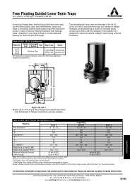
EM <strong>Inverted</strong> <strong>Bucket</strong> <strong>Steam</strong> <strong>Trap</strong><br />
Forged Carbon Steel for Horizontal Installation<br />
For Pressures to 32 bar… Capacities to 480 kg/h<br />
CC<br />
C<br />
<strong>Steam</strong> <strong>Trap</strong>s<br />
D B BB<br />
Description<br />
Armstrong's type EM forged steel inverted bucket steam trap combines<br />
the most reliable steam trap operating principle known in a body, which<br />
can be opened for Easy Maintenance.<br />
• High resistance to wear, corrosion and water hammer.<br />
• <strong>The</strong> free-floating guided lever valve mechanism is “frictionless”<br />
with all wear points heavily reinforced. All working parts are<br />
stainless steel; valve and seat are hardened chrome steel,<br />
individually ground and lapped.<br />
• Freedom from dirt problems. Condensate flow under bottom<br />
edge of bucket keeps sediment and “sludge” in suspension until<br />
discharged by full differential purging action. Valve orifice opens<br />
wide - closes tight. <strong>The</strong>re is no buildup of dirt, no close<br />
clearances to be affected by scale. Under normal conditions of<br />
reasonably “clean steam”, a strainer is not necessary. However,<br />
this is left to the user's discretion.<br />
• Air handling ability. Vent in bucket top provides continuous<br />
automatic air and CO 2 venting with no cooling leg and prevents<br />
air binding. Wiggle wire ensures clean vent hole at all times. Any<br />
steam passing through vent is condensed and discharged as<br />
liquid.<br />
• No steam loss. <strong>Steam</strong> does not reach the water-sealed valve.<br />
• <strong>Inverted</strong> bucket traps require no adjustment and no live steam to<br />
operate.<br />
Maximum operating conditions<br />
Maximum allowable pressure<br />
(vessel design): 32 bar - 250°C<br />
Maximum operating pressure: 32 bar<br />
Maximum back pressure:<br />
99% of inlet pressure<br />
Connections<br />
Screwed BSPT and NPT<br />
Socketweld<br />
Flanged DIN or ANSI (welded)<br />
Materials<br />
Body:<br />
Forged carbon steel<br />
Internals: All stainless steel – 304<br />
Valve and seat: Hardened chrome steel – 440F<br />
Gasket:<br />
Spiral wounded graphite<br />
Bolts:<br />
24 CrMo5<br />
Options<br />
• <strong>Bucket</strong> vent scrubbing wire for heavy dirt/oil conditions<br />
• Probe connection (3/8") for use of <strong>Trap</strong>Alert, the self-diagnostic<br />
steam traps<br />
• For superheated steam we advise stellited valve and seat<br />
Specification<br />
<strong>Inverted</strong> bucket steam trap, type EM in forged steel, with automatic air<br />
vent, free-floating lever mechanism, with the orifice in the top. Maximum<br />
allowable back pressure 99% of inlet pressure.<br />
How to order<br />
Specify:<br />
• Size and type of pipe connection<br />
• Maximum working pressure that will be encountered or orifice<br />
size<br />
• Maximum condensate load<br />
• Any options required<br />
Table ST-88-1. Model EM Side Inlet, Side Outlet <strong>Trap</strong> (dimensions in mm)<br />
Pipe Connections 15 20 25<br />
“C” Face-to-Face (screwed & SW) 98 98 –<br />
“CC” Face-to-Face (flanged PN40*) 150 150 160<br />
“D” Bottom to C L Inlet 189 189 189<br />
“B” Height (screwed & SW) 210 210 –<br />
“BB” Height (flanged PN40*) 235 240 245<br />
Weight in kg (screwed & SW) 3,1 3,1 –<br />
Weight in kg (flanged PN40*) 5,5 7,1 8,1<br />
* Other flange sizes, ratings and face-to-face dimensions are available on request.<br />
All sizes comply with the article 3.3 of the PED (97/23/EC).<br />
All dimensions and weights are approximate. Use certified print for exact dimensions. Design and materials are subject to change without notice.<br />
ST-88<br />
Armstrong International SA • Parc Industriel des Hauts-Sarts (2 e Avenue) • 4040 Herstal • Belgium<br />
Tel.: +32 (0)4 240 90 90 • Fax: +32 (0)4 240 40 33<br />
www.armstronginternational.eu • info@armstronginternational.eu
EM <strong>Inverted</strong> <strong>Bucket</strong> <strong>Steam</strong> <strong>Trap</strong><br />
Forged Carbon Steel for Horizontal Installation<br />
For Pressures to 32 bar… Capacities to 480 kg/h<br />
Table ST-89-1. Model EM Capacity<br />
1,5 3,5<br />
16 113<br />
17,5 1<br />
121<br />
Capacity, kg/h<br />
132<br />
<strong>Steam</strong> <strong>Trap</strong>s<br />
Pressure, bar<br />
All dimensions and weights are approximate. Use certified print for exact dimensions. Design and materials are subject to change without notice.<br />
Armstrong International SA • Parc Industriel des Hauts-Sarts (2 e Avenue) • 4040 Herstal • Belgium<br />
Tel.: +32 (0)4 240 90 90 • Fax: +32 (0)4 240 40 33<br />
www.armstronginternational.eu • info@armstronginternational.eu<br />
ST-89
300 Series <strong>Inverted</strong> <strong>Bucket</strong> <strong>Steam</strong> <strong>Trap</strong>s<br />
Forged Carbon Steel for Vertical Installation<br />
For Pressures to 45 bar...Capacities to 9 000 kg/h<br />
<strong>Steam</strong> <strong>Trap</strong>s<br />
Description<br />
Armstrong offers its 300 Series forged carbon steel traps for vertical<br />
installation with a choice of screwed, socketweld or flanged connections.<br />
A unique leverage system multiplies the force provided by the bucket to<br />
open the valve against system pressure. <strong>The</strong> mechanism is free-floating,<br />
and has no fixed pivots to create wear or friction.<br />
Because the mechanism is located at the top of the trap, no dirt can<br />
collect on the orifice. Small particles of dirt are held in suspension until<br />
discharged by the full differential purging action when the bucket sinks,<br />
pulling the valve off the seat.<br />
<strong>The</strong> discharge orifice is surrounded by a water seal, preventing live<br />
steam loss. Automatic air venting is provided by a small vent hole in the<br />
bucket, which provides continuous automatic air and CO 2 venting at<br />
steam temperature.<br />
<strong>Inverted</strong> bucket traps drain continuously, allowing no condensate<br />
backup. <strong>The</strong>y are also resistant to water hammer.<br />
How to Order<br />
Specify:<br />
• Model number<br />
• Size and type of pipe connection. When flanges are required,<br />
specify type of flange in detail<br />
• Maximum working pressure that will be encountered or orifice<br />
size<br />
• Any options required<br />
A<br />
K<br />
A<br />
K<br />
For Superheat Service:<br />
1. Don’t oversize the orifice; a restricted orifice may be advisable.<br />
2. Specify a burnished valve and seat and an extended inlet tube and<br />
check valve.<br />
3. Provide a drip leg of adequate diameter and length.<br />
4. Provide a generous length (600-900 mm) of inlet piping, with the<br />
trap below the main.<br />
5. Don’t insulate the trap or the inlet piping.<br />
B<br />
BB<br />
Connections<br />
Screwed BSPT and NPT<br />
Socketweld<br />
Flanged DIN or ANSI (welded)<br />
G<br />
Model 300 <strong>Trap</strong><br />
G<br />
Series 300 FW <strong>Trap</strong><br />
Materials<br />
Body:<br />
Internals:<br />
Valve and seat:<br />
ASTM A105<br />
Models 312, 313, 316 are also available with cast<br />
316 stainless steel bodies and allstainless steel<br />
internals<br />
All stainless steel – 304 (larger sizes have cast iron<br />
bucket weights)<br />
Hardened chrome steel – 440F (38 bar)<br />
Options<br />
• Stainless steel internal check valve<br />
• <strong>The</strong>rmic vent bucket 17 bar maximum<br />
• Scrub wire<br />
Specification<br />
<strong>Inverted</strong> bucket steam trap, type ... in forged carbon steel, with<br />
continuous air venting at steam temperature, free-floating stainless steel<br />
mechanism, and discharge orifice at the top of the trap. Maximum<br />
allowable back pressure 99% of inlet pressure.<br />
Table ST-90-1. Pressure-Temperature Rating for Forged Steel <strong>Trap</strong>s<br />
Model<br />
No.<br />
Maximum<br />
Oper. Pr.,<br />
Saturated<br />
<strong>Steam</strong><br />
Maximum Allowable Pressure (Vessel Design) of<br />
Pressure - Containing Parts at Indicated Temperature<br />
-28°C /<br />
+343°C<br />
371°C 399°C 427°C<br />
bar<br />
bar<br />
310 27,5 53 53 50 41<br />
312 41,5 41 41 38,5 34,5<br />
313 45 74 74 67 54<br />
314 45 78 77 68 56<br />
315 45 70 66,5 59 47,5<br />
316 45 76 72 65 52<br />
Notes: Maximum operating pressure to be marked on nameplate will be<br />
determined by actual orifice used.<br />
Maximum allowable pressures shown in boldface will be marked on<br />
nameplate, unless otherwise requested.<br />
<strong>Trap</strong>s with flanges may have different pressure-temperature ratings.<br />
Maximum back pressure is 99% of inlet pressure.<br />
Table ST-90-2. 300 Series Bottom Inlet, Top Outlet <strong>Trap</strong> (dimensions in mm)<br />
Add suffix “CV” to trap number for internal check valve.<br />
Model No. Screwed or SW<br />
Model No. Flanged<br />
310<br />
310-FW<br />
312<br />
312-FW<br />
313<br />
313-FW<br />
314<br />
314-FW<br />
315<br />
315-FW<br />
316<br />
316-FW<br />
Pipe Connections 15 – 20 15 – 20 – 25 15 – 20 – 25 25 – 32 25 – 32 – 40 40 – 50<br />
“A” Flange Diameter 114 171 203 219 248 302<br />
“B” Face-to-Face (screwed & SW) 202 259 295 348 381 435<br />
“BB” Face-to-Face (flanged PN100*) 282 – 287 307 – 314 – 320 343 – 349 – 355 409 – 411 442 – 444 – 446 499 – 505<br />
“G” Body Outside Diameter 78 121 130 146 168 213<br />
“K” C L Outlet to C L Inlet 14,3 31,7 36,5 36,5 44,4 54,0<br />
Number of Bolts 6 6 8 9<br />
Weight in kg (screwed & SW) 4,5 13,6 22,0 31,8 44,5 81,2<br />
Weight in kg (flanged PN100*) 5,5 – 6,5 14,5 – 15,5 – 16 22,5 – 23,5 – 24 36,5 – 37,0 45,5 – 47,5 – 49 85,8 – 87,8<br />
* Other flange sizes, ratings and face-to-face dimensions are available on request.<br />
Shade indicates products that are CE Marked according to the PED (97/23/EC). All the other models comply with the Article 3.3 of the same directive.<br />
All dimensions and weights are approximate. Use certified print for exact dimensions. Design and materials are subject to change without notice.<br />
ST-90<br />
Armstrong International SA • Parc Industriel des Hauts-Sarts (2 e Avenue) • 4040 Herstal • Belgium<br />
Tel.: +32 (0)4 240 90 90 • Fax: +32 (0)4 240 40 33<br />
www.armstronginternational.eu • info@armstronginternational.eu
300 Series <strong>Inverted</strong> <strong>Bucket</strong> <strong>Steam</strong> <strong>Trap</strong>s<br />
Forged Carbon Steel for Vertical Installation<br />
For Pressures to 45 bar...Capacities to 9 000 kg/h<br />
Table ST-91-1. Model 310 Capacity<br />
Table ST-91-2. Model 312 Capacity<br />
Capacity, kg/h<br />
1 2<br />
5 8,5<br />
13,5<br />
17<br />
27,5<br />
Capacity, kg/h<br />
0,7 1<br />
1 1,5 3<br />
4 6 10,5 1<br />
15,5<br />
31<br />
41,5<br />
<strong>Steam</strong> <strong>Trap</strong>s<br />
Pressure, bar<br />
Pressure, bar<br />
Table ST-91-3. Model 313 Capacity<br />
Table ST-91-4. Model 314 Capacity<br />
1<br />
2<br />
14 1 5,5 8,5 1 12,5 17 31<br />
45<br />
1 2 4 5,5 8,5<br />
12,5<br />
17<br />
26<br />
38<br />
Capacity, kg/h<br />
Capacity, kg/h<br />
45<br />
Pressure, bar<br />
Pressure, bar<br />
Table ST-91-5. Model 315 Capacity<br />
Table ST-91-6. Model 316 Capacity<br />
1<br />
2<br />
4<br />
7 9 12,5<br />
15,5<br />
24 34,5<br />
45<br />
1 1,5 3 4 5,5 8,5 12,5<br />
17 25,5<br />
34,5<br />
41,5<br />
Capacity, kg/h<br />
Capacity, kg/h<br />
45<br />
Pressure, bar<br />
Pressure, bar<br />
All dimensions and weights are approximate. Use certified print for exact dimensions. Design and materials are subject to change without notice.<br />
Armstrong International SA • Parc Industriel des Hauts-Sarts (2 e Avenue) • 4040 Herstal • Belgium<br />
Tel.: +32 (0)4 240 90 90 • Fax: +32 (0)4 240 40 33<br />
www.armstronginternational.eu • info@armstronginternational.eu<br />
ST-91
411G/421 <strong>Inverted</strong> <strong>Bucket</strong> <strong>Steam</strong> <strong>Trap</strong>s<br />
Forged Carbon Steel for Vertical and Horizontal Installation<br />
For Pressures to 69 bar...Capacities to 590 kg/h<br />
A<br />
K<br />
CC<br />
C<br />
<strong>Steam</strong> <strong>Trap</strong>s<br />
B<br />
BB<br />
B<br />
G<br />
Model 411G <strong>Trap</strong><br />
G<br />
Model 421 <strong>Trap</strong><br />
Description<br />
Armstrong Model 411G vertical installation and Model 421 horizontal<br />
installation offer smaller capacities at higher pressures.<br />
A unique leverage system multiplies the force provided by the bucket to<br />
open the valve against system pressure. <strong>The</strong> mechanism is free-floating<br />
and has no fixed pivots to create wear or friction.<br />
Because the mechanism is located at the top of the trap, no dirt can<br />
collect on the orifice. Small particles of dirt are held in suspension until<br />
discharged by the full differential purging action when the bucket sinks,<br />
pulling the valve off the seat.<br />
<strong>The</strong> discharge orifice is surrounded by a water seal, preventing live<br />
steam loss. Automatic air venting is provided by a small vent hole in the<br />
bucket.<br />
<strong>Inverted</strong> bucket traps drain continuously to prevent condensate backup.<br />
<strong>The</strong>y are also resistant to water hammer.<br />
Model 421 adds the convenience and savings of in-line repairability and<br />
is designed to meet today’s energy management requirements efficiently<br />
and economically over a long, trouble-free service life.<br />
Connections<br />
Screwed BSPT and NPT<br />
Socketweld<br />
Flanged DIN or ANSI (welded)<br />
Materials<br />
Body:<br />
ASTM A105<br />
411G Cap:<br />
ASTM A105<br />
421 Cap: ASTM A216 WCB<br />
Internals: All stainless steel – 304<br />
Valve and seat:<br />
Titanium<br />
Options<br />
Stainless steel internal check valve (411G only)<br />
Specifications<br />
<strong>Inverted</strong> bucket steam trap, type ... in forged carbon steel, with<br />
continuous air venting at steam temperature, free-floating stainless steel<br />
mechanism, with the discharge orifice at the top of the trap. Maximum<br />
allowable back pressure 99% of inlet pressure.<br />
How to Order<br />
Specify:<br />
• Model number<br />
• Size and type of pipe connection. When flanges are required,<br />
specify type of flange in detail<br />
• Maximum working pressure that will be encountered or orifice<br />
size<br />
• Any options required<br />
Table ST-92-1. Model 411G Bottom Inlet, Top Outlet <strong>Trap</strong>; Model 421 Side Inlet, Side Outlet <strong>Trap</strong> (dimensions in mm)<br />
Add suffix “CV” to trap number for internal check valve.<br />
Model No. Screwed or SW<br />
Model No. Flanged<br />
411G<br />
411G-FW<br />
421<br />
421-FW<br />
Pipe Connections 15 – 20 15 – 20<br />
“A” Flange Diameter 160 –<br />
“B” & “C” Face-to-Face (screwed & SW) 224 203<br />
“BB” & “CC” Face-to-Face (flanged PN100*) 298 – 304 277 – 283<br />
“G” Body Outside Diameter 103 98<br />
“K” C L Outlet to C L Inlet 19 –<br />
Number of Bolts 8 8<br />
Weight in kg (screwed & SW) 11,3 12,6<br />
Weight in kg (flanged PN100*) 14,4 – 15,4 15,1 – 16,1<br />
* Other flange sizes, ratings and face-to-face dimensions are available on request.<br />
All models comply with the article 3.3 of the PED (97/23/EC).<br />
All dimensions and weights are approximate. Use certified print for exact dimensions. Design and materials are subject to change without notice.<br />
ST-92<br />
Armstrong International SA • Parc Industriel des Hauts-Sarts (2 e Avenue) • 4040 Herstal • Belgium<br />
Tel.: +32 (0)4 240 90 90 • Fax: +32 (0)4 240 40 33<br />
www.armstronginternational.eu • info@armstronginternational.eu
411G/421 <strong>Inverted</strong> <strong>Bucket</strong> <strong>Steam</strong> <strong>Trap</strong>s<br />
Forged Carbon Steel for Vertical and Horizontal Installation<br />
For Pressures to 69 bar...Capacities to 590 kg/h<br />
Table ST-93-1. Model 411G and 421 Capacity<br />
41,5<br />
69<br />
Capacity, kg/h<br />
<strong>Steam</strong> <strong>Trap</strong>s<br />
Pressure, bar<br />
Note: #38 orifice in Model 421 is limited to 39 bar.<br />
Table ST-93-2. Pressure-Temperature Rating for Forged Steel <strong>Trap</strong>s<br />
Maximum Operating Max. Allowable Pressure (Vessel Design) of Pressure-Containing Parts at Indicated Temp.<br />
Model No. Pressure, Saturated <strong>Steam</strong> -21 / +371°C 399°C 427°C<br />
bar<br />
bar<br />
411G / 421 69 69 65,5 58<br />
Notes: Maximum operating pressure to be marked on nameplate will be determined by actual orifice used.<br />
Maximum allowable pressures shown in boldface will be marked on nameplate, unless otherwise requested.<br />
<strong>Trap</strong>s with flanges may have different pressure-temperature ratings.<br />
Maximum back pressure is 99% of inlet pressure.<br />
All dimensions and weights are approximate. Use certified print for exact dimensions. Design and materials are subject to change without notice.<br />
Armstrong International SA • Parc Industriel des Hauts-Sarts (2 e Avenue) • 4040 Herstal • Belgium<br />
Tel.: +32 (0)4 240 90 90 • Fax: +32 (0)4 240 40 33<br />
www.armstronginternational.eu • info@armstronginternational.eu<br />
ST-93
400 Series <strong>Inverted</strong> <strong>Bucket</strong> <strong>Steam</strong> <strong>Trap</strong>s<br />
Forged Chrome-moly Steel for Vertical Installation<br />
For Pressures to 69 bar...Capacities to 9 000 kg/h<br />
<strong>Steam</strong> <strong>Trap</strong>s<br />
Description<br />
Armstrong offers its 400 Series forged chrome-moly steel traps for<br />
vertical installation with a choice of screwed, socketweld or flanged<br />
connections.<br />
A unique leverage system multiplies the force provided by the bucket to<br />
open the valve against system pressure. <strong>The</strong> mechanism is free-floating<br />
and has no fixed pivots to create wear or friction.<br />
Because the mechanism is located at the top of the trap, no dirt can<br />
collect on the orifice. Small particles of dirt are held in suspension until<br />
discharged by the full differential purging action when the bucket sinks,<br />
pulling the valve off the seat.<br />
<strong>The</strong> discharge orifice is surrounded by a water seal, preventing live<br />
steam loss. Automatic air venting is provided by a small vent hole in the<br />
bucket. This provides continuous automatic air and CO 2 venting at<br />
steam temperature.<br />
<strong>Inverted</strong> bucket traps drain continuously to prevent condensate backup.<br />
<strong>The</strong>y are also resistant to water hammer.<br />
Operation on Superheat. A normally operating bucket trap is filled with<br />
saturated steam and condensate. Superheated steam can enter only as<br />
fast as the steam inside can condense. As a result, the temperature of<br />
the trap is at (or slightly below) saturated steam temperature, regardless<br />
of the degree of superheat.<br />
<strong>Trap</strong> Selection. <strong>The</strong> pressure-containing parts of the steam trap should<br />
safely withstand the maximum pressure and temperature conditions of<br />
the system. For example, a trap is required for a 62 bar main at 482°C.<br />
<strong>The</strong> normal operating temperature of the trap will be about 278°C. A<br />
Model 415 trap should be selected, even though several smaller traps<br />
are capable of handling the working pressure.<br />
Materials<br />
Body: ASTM A182 F22 Class 3<br />
Models 413 and 415 are available with<br />
cast 316 stainless steel bodies and all<br />
stainless steel internals<br />
Internals: All stainless steel – 304<br />
Valve and seat:<br />
Hardened chrome steel – 440F (38 bar)<br />
Options<br />
Stainless steel internal check valve<br />
Specification<br />
<strong>Inverted</strong> bucket steam trap, type ... in forged chrome-moly steel, with<br />
continuous air venting at steam temperature, free-floating stainless steel<br />
mechanism, with the discharge orifice at the top of the trap. Maximum<br />
allowable back pressure 99% of inlet pressure.<br />
How to Order<br />
Specify:<br />
• Model number<br />
• Size and type of pipe connection. When flanges are required,<br />
specify type of flange in detail<br />
• Maximum working pressure that will be encountered or orifice<br />
size<br />
• Any options required<br />
For Superheat Service:<br />
1. Don’t oversize the orifice; a restricted orifice may be advisable.<br />
2. Specify a burnished valve and seat and an extended inlet tube and<br />
check valve.<br />
3. Provide a drip leg of adequate diameter and length.<br />
4. Provide a generous length (600-900 mm) of inlet piping, with the<br />
trap below the main.<br />
5. Don’t insulate the trap or the inlet piping.<br />
A<br />
K<br />
A<br />
K<br />
Connections<br />
Screwed BSPT and NPT<br />
Socketweld<br />
Flanged DIN or ANSI (welded)<br />
B<br />
BB<br />
G<br />
Model 400 <strong>Trap</strong><br />
G<br />
Series 400 FW <strong>Trap</strong><br />
Table ST-94-1. 400 Series Bottom Inlet, Top Outlet <strong>Trap</strong> (dimensions in mm)<br />
Add suffix “CV” to trap number for internal check valve.<br />
Model No. Screwed or SW<br />
Model No. Flanged<br />
413<br />
413-FW<br />
415<br />
415-FW<br />
416<br />
416-FW<br />
Pipe Connections 15 – 20 – 25 25 – 32 – 40 40 – 50<br />
“A” Flange Diameter 219 273 317<br />
“B” Face-to-Face (screwed & SW) 305 379 448<br />
“BB” Face-to-Face (flanged PN100*) 353 – 360 – 366 440 – 444 – 446 513 – 519<br />
“G” Body Outside Diameter 137 175 216<br />
“K” C L Outlet to C L Inlet 36,5 44,4 54<br />
Number of Bolts 8 9 12<br />
Weight in kg (screwed & SW) 29,5 57,2 88,0<br />
Weight in kg (flanged PN100*) 31,5 – 32,5 – 33,0 58,0 – 60,0 – 61,5 92,5 – 94,5<br />
* Other flange sizes, ratings and face-to-face dimensions are available on request.<br />
All models are CE Marked according to the PED (97/23/EC).<br />
All dimensions and weights are approximate. Use certified print for exact dimensions. Design and materials are subject to change without notice.<br />
ST-94<br />
Armstrong International SA • Parc Industriel des Hauts-Sarts (2 e Avenue) • 4040 Herstal • Belgium<br />
Tel.: +32 (0)4 240 90 90 • Fax: +32 (0)4 240 40 33<br />
www.armstronginternational.eu • info@armstronginternational.eu
400 Series <strong>Inverted</strong> <strong>Bucket</strong> <strong>Steam</strong> <strong>Trap</strong>s<br />
Forged Chrome-moly Steel for Vertical Installation<br />
For Pressures to 69 bar...Capacities to 9 000 kg/h<br />
Table ST-95-1. Model 413 Capacity<br />
Table ST-95-2. Model 415 Capacity<br />
1 2<br />
4<br />
5,5 8,5<br />
12,5<br />
17 31 65,5<br />
1 2 4<br />
7 9 12,515,5<br />
24 34,5<br />
55<br />
69<br />
Capacity, kg/h<br />
Capacity, kg/h<br />
69<br />
<strong>Steam</strong> <strong>Trap</strong>s<br />
Pressure, bar<br />
Pressure, bar<br />
Table ST-95-3. Model 416 Capacity<br />
Capacity, kg/h<br />
1 1,7 3 4 5,5 8,5 12,5<br />
17<br />
25,5<br />
34,5<br />
41,5<br />
48,5<br />
69<br />
Pressure, bar<br />
Table ST-95-4. Pressure-Temperature Rating for Forged Steel <strong>Trap</strong>s<br />
Maximum Operating Pressure, Max. Allowable Pressure (Vessel Design) of Pressure-Containing Parts at Indicated Temp.<br />
Model No.<br />
Saturated <strong>Steam</strong><br />
-28 / +399°C 427°C 454°C 482°C<br />
bar<br />
bar<br />
413 69 83 83 72 54<br />
415 69 76 76 74,5 66,5<br />
416 69 117 114 93 68<br />
Notes: Maximum operating pressure to be marked on nameplate will be determined by actual orifice used.<br />
Maximum allowable pressures shown in boldface will be marked on nameplate, unless otherwise requested.<br />
<strong>Trap</strong>s with flanges may have different pressure-temperature ratings.<br />
Maximum back pressure is 99% of inlet pressure.<br />
All dimensions and weights are approximate. Use certified print for exact dimensions. Design and materials are subject to change without notice.<br />
Armstrong International SA • Parc Industriel des Hauts-Sarts (2 e Avenue) • 4040 Herstal • Belgium<br />
Tel.: +32 (0)4 240 90 90 • Fax: +32 (0)4 240 40 33<br />
www.armstronginternational.eu • info@armstronginternational.eu<br />
ST-95
401-SH/501-SH <strong>Inverted</strong> <strong>Bucket</strong> Superheated <strong>Steam</strong> <strong>Trap</strong>s<br />
Carbon Steel or Stainless Steel for Vertical Installation<br />
For Pressures to 106 bar...Capacities to 430 kg/h<br />
<strong>Steam</strong> <strong>Trap</strong>s<br />
BB<br />
A<br />
B<br />
B<br />
A<br />
BB<br />
Model 401-SH<br />
Description<br />
Armstrong’s 401-SH/501-SH Series inverted bucket steam trap line is<br />
made for overcoming the difficult combination of superheat and<br />
high pressure/low load service.<br />
Model 501-SH<br />
Maximum Operating Conditions<br />
Maximum allowable pressure (vessel design):<br />
Model 401-SH: 69 bar @ 427°C<br />
Model 501-SH: 106 bar @ 454°C<br />
To survive this most severe steam service, Armstrong created an<br />
inverted bucket trap with a unique accumulation chamber. <strong>The</strong> chamber<br />
collects sufficient condensate to ensure full discharge cycles. A cup in<br />
the chamber floats up and down on the steam inlet tube, sealing it off as<br />
the condensate level rises. At the same time as the chamber collects<br />
condensate, steam continues to flow under the bucket, making sure that<br />
the discharge valve closes tightly until the condensate rises into the trap<br />
body and the bucket falls down. <strong>The</strong> operation is on/off, no throttling or<br />
dribbling.<br />
Furthermore, it combines all the advantages of an inverted bucket steam<br />
trap:<br />
• High resistance to wear, corrosion and water hammer with no<br />
gaskets.<br />
• A unique leverage system multiplies the force provided by the<br />
bucket, to open the valve against system pressure.<br />
• <strong>The</strong> mechanism is located at the top. No dirt can collect on the<br />
orifice. Small particles of dirt will be held in suspension until<br />
discharged by the full differential purging action.<br />
• <strong>The</strong> discharge orifice is surrounded by a water seal, preventing<br />
live steam loss. Automatic air venting is provided by a small hole<br />
in the bucket.<br />
• <strong>Inverted</strong> bucket traps require no adjustment. <strong>The</strong>y do not allow<br />
condensate backup and are resistant to water hammer.<br />
Connections<br />
Screwed BSPT and NPT (401-SH only)<br />
Socketweld<br />
Flanged DIN or ANSI (welded)<br />
Maximum operating pressure:<br />
Model 401-SH: 69 bar<br />
Model 501-SH: 106 bar<br />
Maximum back pressure: 99% of inlet pressure<br />
Materials<br />
Body:<br />
Model 401-SH Carbon steel ASTM A106 Gr. B Sch. 80 pipe<br />
Model 501-SH Stainless steel 316L ASTM A312 Sch. 80 pipe<br />
Internals: Stainless steel – 304<br />
Valve and seat: Titanium<br />
Connections:<br />
Model 401-SH Stainless steel – 304<br />
Model 501-SH Stainless steel – 316L<br />
Specification<br />
<strong>Inverted</strong> bucket steam trap, type 401-SH in carbon steel or 501-SH in<br />
stainless steel, with accumulation chamber, continuous air venting at<br />
steam temperature, stainless steel leverage system, with the discharge<br />
orifice at the top of the trap. Maximum allowable back pressure 99% of<br />
inlet pressure.<br />
How to Order<br />
Specify:<br />
• Model number<br />
• Size and type of pipe connection. When flanges are required,<br />
specify type of flange in detail<br />
• Maximum working pressure that will be encountered or orifice<br />
size<br />
Table ST-96-1. Model 401-SH and Model 501-SH Bottom Inlet, Top Outlet <strong>Trap</strong> (dimensions in mm)<br />
Model No. 401-SH 501-SH<br />
Pipe Connections 15 – 20 15 – 20<br />
“A” Body Outside Diameter 100 100<br />
“B” Face-to-Face (screwed & SW) 260 – 253 350<br />
“BB” Height (flanged 401-SH PN100 & 501-SH PN250*) 353 – 363 476 – 480<br />
Weight in kg (screwed & SW) 5,5 7<br />
Weight in kg (flanged 401-SH PN100 & 501-SH PN250*) 6,7 – 7,3 13 – 13,5<br />
* Other flange sizes, ratings and face-to-face dimensions are available on request.<br />
All models are CE Marked according to the PED (97/23/EC).<br />
All dimensions and weights are approximate. Use certified print for exact dimensions. Design and materials are subject to change without notice.<br />
ST-96<br />
Armstrong International SA • Parc Industriel des Hauts-Sarts (2 e Avenue) • 4040 Herstal • Belgium<br />
Tel.: +32 (0)4 240 90 90 • Fax: +32 (0)4 240 40 33<br />
www.armstronginternational.eu • info@armstronginternational.eu
401-SH/501-SH <strong>Inverted</strong> <strong>Bucket</strong> Superheated <strong>Steam</strong> <strong>Trap</strong>s<br />
Carbon Steel or Stainless Steel for Vertical Installation<br />
For Pressures to 106 bar...Capacities to 590 kg/h<br />
Installation Recommendations<br />
What little condensate there is on superheat and high pressure/low load<br />
service usually forms in drip legs and in the traps themselves. <strong>The</strong>refore<br />
proper piping and drip legs of adequate size and diameter are essential<br />
for the successful operation of the Armstrong superheat trap.<br />
Table ST-97-1. Model 401/501 Capacity<br />
105<br />
69<br />
Capacity, kg/h<br />
<strong>Steam</strong> <strong>Trap</strong>s<br />
Correctly<br />
Sized<br />
Incorrectly<br />
Sized<br />
Pressure, bar<br />
Drip Leg Sizing<br />
<strong>The</strong> properly sized drip leg will capture condensate. Too small a drip leg<br />
can actually cause a venturi “piccolo” effect where pressure drop pulls<br />
condensate out of the drip leg and trap.<br />
D<br />
<strong>Trap</strong> Draining Drip Leg on <strong>Steam</strong> Main<br />
Air <strong>Steam</strong> Condensate<br />
H<br />
M<br />
Table ST-97-2. Recommended <strong>Steam</strong> Main and Branch Line Drip Leg<br />
Tracing<br />
M D H Drip Leg Length Minimum<br />
<strong>Steam</strong> Main Size<br />
Drip Leg<br />
Diameter<br />
Supervised<br />
Warm-Up<br />
Automatic<br />
Warm-Up<br />
mm in. mm in. mm in. mm in.<br />
15 1/2" 15 1/2" 250 10" 710 28"<br />
20 3/4" 20 3/4" 250 10" 710 28"<br />
25 1" 25 1" 250 10" 710 28"<br />
50 2" 50 2" 250 10" 710 28"<br />
75 3" 75 3" 250 10" 710 28"<br />
100 4" 100 4" 250 10" 710 28"<br />
150 6" 100 4" 250 10" 710 28"<br />
200 8" 100 4" 300 12" 710 28"<br />
250 10" 150 6" 380 15" 710 28"<br />
300 12" 150 6" 450 18" 710 28"<br />
350 14" 200 8" 530 21" 710 28"<br />
400 16" 200 8" 600 24" 710 28"<br />
450 18" 250 10" 685 27" 710 28"<br />
500 20" 250 10" 760 30" 760 30"<br />
600 24" 300 12" 910 36" 910 36"<br />
<strong>Trap</strong> Chamber<br />
Cup<br />
<strong>Steam</strong><br />
Tube<br />
Accumulation<br />
Chamber<br />
Condensate<br />
Tube<br />
Cycling – Discharge Valve Wide Open<br />
With the steam feed tube to the trap<br />
chamber sealed, condensate flows<br />
through the condensate feed tube (from<br />
accumulation chamber) into the trap<br />
chamber. This sinks the inverted bucket,<br />
which opens the discharge valve, cycling<br />
the trap.<br />
Cycle Ending<br />
As the level of condensate in the<br />
accumulation chamber falls, the cup<br />
sealing the steam feed tube moves<br />
downward, opening a passage for steam<br />
to flow into trap chamber.<br />
<strong>Trap</strong> Closed<br />
As steam begins to flow through the<br />
accumulation chamber and up the<br />
steam feed tube under the inverted<br />
bucket in the trap chamber, the<br />
discharge valve closes tightly.<br />
Cycle About to Repeat<br />
As the level of condensate rises in the<br />
accumulation chamber, the cup floats up<br />
until it again seals the steam feed tube,<br />
and the cycle repeats.<br />
All dimensions and weights are approximate. Use certified print for exact dimensions. Design and materials are subject to change without notice.<br />
Armstrong International SA • Parc Industriel des Hauts-Sarts (2 e Avenue) • 4040 Herstal • Belgium<br />
Tel.: +32 (0)4 240 90 90 • Fax: +32 (0)4 240 40 33<br />
www.armstronginternational.eu • info@armstronginternational.eu<br />
ST-97
5000 Series <strong>Inverted</strong> <strong>Bucket</strong> <strong>Steam</strong> <strong>Trap</strong>s<br />
Forged Chrome-moly Steel for Vertical Installation<br />
For Pressures to 124 bar...Capacities to 2 340 kg/h<br />
A<br />
K<br />
A<br />
K<br />
<strong>Steam</strong> <strong>Trap</strong>s<br />
B<br />
BB<br />
G<br />
Series 5133G & 5155G <strong>Trap</strong>s<br />
G<br />
Series 5133G-FW & 5155G-FW <strong>Trap</strong>s<br />
Description<br />
Armstrong offers its 5000 Series forged chrome-moly steel traps for<br />
vertical installation with a choice of screwed, socketweld or flanged<br />
connections.<br />
A unique leverage system multiplies the force provided by the bucket to<br />
open the valve against system pressure. <strong>The</strong> mechanism is free-floating<br />
and has no fixed pivots to create wear or friction.<br />
Because the mechanism is located at the top of the trap, no dirt can<br />
collect on the orifice. Small particles of dirt are held in suspension until<br />
discharged by the full differential purging action when the bucket sinks,<br />
pulling the valve off the seat.<br />
<strong>The</strong> discharge orifice is surrounded by a water seal, preventing live<br />
steam loss. Automatic air venting is provided by a small vent hole in the<br />
bucket. This provides continuous automatic air and CO 2 venting at<br />
steam temperature.<br />
<strong>Inverted</strong> bucket traps drain continuously, although discharging<br />
intermittently, to prevent condensate backup. <strong>The</strong>y are also resistant to<br />
water hammer.<br />
For Superheat Service:<br />
1. Don’t oversize the orifice; a restricted orifice may be advisable.<br />
2. Specify a burnished valve and seat and an extended inlet tube and<br />
check valve.<br />
3. Provide a drip leg of adequate diameter and length.<br />
4. Provide a generous length (600-900 mm) of inlet piping, with the<br />
trap below the main.<br />
5. Don’t insulate the trap or the inlet piping.<br />
Connections<br />
Screwed BSPT and NPT<br />
Socketweld<br />
Flanged DIN or ANSI (welded)<br />
Materials<br />
Body: ASTM A182 F22 Class 3<br />
Internals: All stainless steel – 304<br />
Valve and seat: Titanium<br />
Options<br />
• Stainless steel internal check valve<br />
• Burnished valve and seat<br />
Operation on Superheat. A normally operating bucket trap is filled with<br />
saturated steam and condensate. Superheated steam can enter only as<br />
fast as the steam inside can condense. As a result, the temperature of<br />
the trap is at (or slightly below) saturated steam temperature, regardless<br />
of the degree of superheat.<br />
<strong>Trap</strong> Selection. <strong>The</strong> pressure-containing parts of the steam trap should<br />
safely withstand the maximum pressure and temperature conditions of<br />
the system. For example, a trap is required for a 68 bar main at 510°C.<br />
<strong>The</strong> normal operating temperature of the trap will be about 286°C.<br />
A Model 5133G trap should be selected, even though several smaller<br />
traps are capable of handling the working pressure.<br />
Table ST-98-1. 5000 Series Bottom Inlet, Top Outlet <strong>Trap</strong> (dimensions in mm)<br />
Add suffix “CV” to trap number for internal check valve.<br />
Model No. Screwed or SW<br />
Model No. Flanged<br />
5133G<br />
5133G-FW<br />
5155G<br />
5155G-FW<br />
Pipe Connections 15 – 20 – 25 20 – 25 – 32<br />
“A” Flange Diameter 216 264<br />
“B” Face-to-Face (screwed & SW) 362 412<br />
“BB” Face-to-Face (flanged PN160*) 457 – 463 – 470 540 – 540 – 540<br />
“G” Body Outside Diameter 146 194<br />
“K” C L Outlet to C L Inlet 33,0 44,5<br />
Number of Bolts 8 10<br />
Weight in kg (screwed & SW) 44,5 77,5<br />
Weight in kg (flanged PN160*) 47,0 – 47,5 – 48,0 89,0 – 89,5 – 90,0<br />
* Other flange sizes, ratings and face-to-face dimensions are available on request.<br />
All models are CE Marked according to the PED (97/23/EC).<br />
All dimensions and weights are approximate. Use certified print for exact dimensions. Design and materials are subject to change without notice.<br />
ST-98<br />
Armstrong International SA • Parc Industriel des Hauts-Sarts (2 e Avenue) • 4040 Herstal • Belgium<br />
Tel.: +32 (0)4 240 90 90 • Fax: +32 (0)4 240 40 33<br />
www.armstronginternational.eu • info@armstronginternational.eu
5000 Series <strong>Inverted</strong> <strong>Bucket</strong> <strong>Steam</strong> <strong>Trap</strong>s<br />
Forged Chrome-moly Steel for Vertical Installation<br />
For Pressures to 124 bar...Capacities to 2 340 kg/h<br />
Table ST-99-1. Model 5133G Capacity<br />
Table ST-99-2. Model 5155G Capacity<br />
55<br />
83<br />
93<br />
Capacity, kg/h<br />
103<br />
Capacity, kg/h<br />
124<br />
<strong>Steam</strong> <strong>Trap</strong>s<br />
Pressure, bar<br />
Pressure, bar<br />
Table ST-99-3. Pressure-Temperature Rating for Forged Steel <strong>Trap</strong>s<br />
Maximum Operating Pressure, Maximum Allowable Pressure (Vessel Design) of Pressure-Containing Parts at Indicated Temperature<br />
Model No. Saturated <strong>Steam</strong> -28 / +343°C 371°C 399°C 427°C 454°C 482°C 510°C 538°C<br />
bar<br />
5133G 103 146 146 146 146 137 119 93 64<br />
5155G 124 174 174 174 174 163 143 111 76,5<br />
Notes: Maximum operating pressure to be marked on nameplate will be determined by actual orifice used.<br />
Maximum allowable pressures shown in boldface will be marked on nameplate, unless otherwise requested.<br />
<strong>Trap</strong>s with flanges may have different pressure-temperature ratings.<br />
Maximum back pressure is 99% of inlet pressure.<br />
bar<br />
Options<br />
Internal Check Valves are spring loaded stainless steel and screw into<br />
an extended inlet tube having a pipe coupling at the top to save fittings,<br />
labor and money. Internal check valves may result in slightly reduced<br />
capacities.<br />
Screwed Connections are available in all sizes for pressures of 63 bar<br />
or less. <strong>Trap</strong>s for pressures of 63 bar or higher are available with<br />
socketweld or flanged connections.<br />
Specification<br />
<strong>Inverted</strong> bucket steam trap, type ... in forged chrome-moly steel, with<br />
continuous air venting at steam temperature, free-floating stainless steel<br />
mechanism, with the discharge orifice at the top of the trap. Maximum<br />
allowable back pressure 99% of inlet pressure.<br />
How to Order<br />
Specify:<br />
• Model number<br />
• Size and type of pipe connection. When flanges are required,<br />
specify type of flange in detail<br />
• Maximum working pressure that will be encountered or orifice<br />
size<br />
• Any options required<br />
All dimensions and weights are approximate. Use certified print for exact dimensions. Design and materials are subject to change without notice.<br />
Armstrong International SA • Parc Industriel des Hauts-Sarts (2 e Avenue) • 4040 Herstal • Belgium<br />
Tel.: +32 (0)4 240 90 90 • Fax: +32 (0)4 240 40 33<br />
www.armstronginternational.eu • info@armstronginternational.eu<br />
ST-99
6000 Series <strong>Inverted</strong> <strong>Bucket</strong> <strong>Steam</strong> <strong>Trap</strong>s<br />
Forged Chrome-moly Steel for Vertical Installation<br />
For Pressures to 186 bar...Capacities to 2 950 kg/h<br />
<strong>Steam</strong> <strong>Trap</strong>s<br />
Description<br />
Armstrong offers its 6000 Series forged chrome-moly steel traps for<br />
vertical installation with a choice of socketweld or flanged connections.<br />
A unique leverage system multiplies the force provided by the bucket to<br />
open the valve against system pressure. <strong>The</strong> mechanism is free-floating<br />
and has no fixed pivots to create wear or friction.<br />
Because the mechanism is located at the top of the trap, no dirt can<br />
collect on the orifice. Small particles of dirt are held in suspension until<br />
discharged by the full differential purging action when the bucket sinks,<br />
pulling the valve off the seat.<br />
<strong>The</strong> discharge orifice is surrounded by a water seal, preventing live<br />
steam loss. Automatic air venting is provided by a small vent hole in the<br />
bucket. This provides continuous automatic air and CO 2 venting at<br />
steam temperature.<br />
<strong>Inverted</strong> bucket traps drain continuously, although discharging<br />
intermittently, to prevent condensate backup. <strong>The</strong>y are also resistant to<br />
water hammer.<br />
Operation on Superheat. A normally operating bucket trap is filled with<br />
saturated steam and condensate. Superheated steam can enter only as<br />
fast as the steam inside can condense. As a result, the temperature of the<br />
trap is at (or slightly below) saturated steam temperature, regardless of the<br />
degree of superheat.<br />
Options<br />
• Stainless steel internal check valve<br />
• Burnished valve and seat<br />
Screwed connections are available in all sizes for pressures of 62 bar or<br />
less. <strong>Trap</strong>s for pressures of 62 bar or higher are available with<br />
socketweld or flanged connections.<br />
Specification<br />
<strong>Inverted</strong> bucket steam trap, type 6155 in forged chrome-moly steel, with<br />
continuous air venting at steam temperature, free-floating stainless steel<br />
mechanism, with the discharge orifice at the top of the trap. Maximum<br />
allowable back pressure 99% of inlet pressure.<br />
How to Order<br />
Specify:<br />
• Model number<br />
• Size and type of pipe connection. When flanges are required,<br />
specify type of flange in detail<br />
• Maximum working pressure that will be encountered or orifice<br />
size<br />
• Any options required<br />
<strong>Trap</strong> Selection. <strong>The</strong> pressure-containing parts of the steam trap should<br />
safely withstand the maximum pressure and temperature conditions of<br />
the system. For example, a trap is required for a 102 bar main at 538°C.<br />
<strong>The</strong> normal operating temperature of the trap will be about 299°C. A<br />
Model 6155G trap should be selected, even though several smaller traps<br />
are capable of handling the working pressure.<br />
For Superheat Service:<br />
1. Don’t oversize the orifice; a restricted orifice may be advisable.<br />
2. Specify a burnished valve and seat and an extended inlet tube and<br />
check valve.<br />
3. Provide a drip leg of adequate diameter and length.<br />
4. Provide a generous length (600-900 mm) of inlet piping, with the<br />
trap below the main.<br />
5. Don’t insulate the trap or the inlet piping.<br />
Connections<br />
Socketweld<br />
Flanged DIN or ANSI (welded)<br />
Materials<br />
Body: ASTM A182 F22 Class 3<br />
Internals: All stainless steel – 304<br />
Valve and seat: Titanium<br />
A<br />
K<br />
B<br />
G<br />
Model 6000 <strong>Trap</strong><br />
A<br />
K<br />
BB<br />
G<br />
Series 6000 FW <strong>Trap</strong><br />
Table ST-100-1. 6000 Series Bottom Inlet, Top Outlet <strong>Trap</strong> (dimensions in mm)<br />
Add suffix “CV” to trap number for internal check valve.<br />
Model No. Screwed or SW<br />
Model No. Flanged<br />
6155G<br />
6155G-FW<br />
Pipe Connections 25 – 32<br />
“A” Flange Diameter 300<br />
“B” Face-to-Face (SW) 613<br />
“BB” Face-to-Face (flanged PN250*) 740 – 740<br />
“G” Body Outside Diameter 213<br />
“K” C L Outlet to C L Inlet 44,5<br />
Number of Bolts 10<br />
Weight in kg (SW) 147,4<br />
Weight in kg (flanged PN250*) 151,0 – 154,0<br />
* Other flange sizes, ratings and face-to-face dimensions are available on request.<br />
All models are CE Marked according to the PED (97/23/EC).<br />
All dimensions and weights are approximate. Use certified print for exact dimensions. Design and materials are subject to change without notice.<br />
ST-100<br />
Armstrong International SA • Parc Industriel des Hauts-Sarts (2 e Avenue) • 4040 Herstal • Belgium<br />
Tel.: +32 (0)4 240 90 90 • Fax: +32 (0)4 240 40 33<br />
www.armstronginternational.eu • info@armstronginternational.eu
6000 Series <strong>Inverted</strong> <strong>Bucket</strong> <strong>Steam</strong> <strong>Trap</strong>s<br />
Forged Chrome-moly Steel for Vertical Installation<br />
For Pressures to 186 bar...Capacities to 2 950 kg/h<br />
Table ST-101-1. Model 6155G Capacity<br />
138<br />
172<br />
Capacity, kg/h<br />
186<br />
<strong>Steam</strong> <strong>Trap</strong>s<br />
Pressure, bar<br />
Table ST-101-2. Pressure-Temperature Rating for Forged Steel <strong>Trap</strong>s<br />
Model No.<br />
Maximum Operating Pressure,<br />
Saturated <strong>Steam</strong><br />
bar<br />
Maximum Allowable Pressure (Vessel Design) of Pressure-Containing Parts at Indicated Temperature<br />
-28 / +343°C 371°C 399°C 427°C 454°C 482°C 510°C 538°C<br />
6155G 186 241 241 241 241 241 213 166 114<br />
Notes: Maximum operating pressure to be marked on nameplate will be determined by actual orifice used.<br />
Maximum allowable pressures shown in boldface will be marked on nameplate, unless otherwise requested.<br />
<strong>Trap</strong>s with flanges may have different pressure-temperature ratings.<br />
Maximum back pressure is 99% of inlet pressure.<br />
bar<br />
Options<br />
Internal Check Valves are spring loaded stainless steel and screw into<br />
an extended inlet tube having a pipe coupling at the top to save fittings,<br />
labor and money. Internal check valves may result in slightly reduced<br />
capacities.<br />
All dimensions and weights are approximate. Use certified print for exact dimensions. Design and materials are subject to change without notice.<br />
Armstrong International SA • Parc Industriel des Hauts-Sarts (2 e Avenue) • 4040 Herstal • Belgium<br />
Tel.: +32 (0)4 240 90 90 • Fax: +32 (0)4 240 40 33<br />
www.armstronginternational.eu • info@armstronginternational.eu<br />
ST-101
2000 Series Stainless Steel <strong>Steam</strong> <strong>Trap</strong>s<br />
<strong>The</strong> Armstrong stainless steel traps – Series 1000, Series U-<br />
1000, Series 1800 and Series 2000 – have high resistance to<br />
damage from freeze-ups. <strong>The</strong>y also offer high resistance to<br />
wear and corrosion for longer service reliability, and they<br />
provide continuous air venting.<br />
Armstrong stainless steel traps provide maximum ease and<br />
economy of installation, inspection or replacement. What’s<br />
more, an Armstrong stainless steel trap is the ideal solution for<br />
trapping applications such as tracer lines, steam mains and<br />
heating and processing applications.<br />
<strong>Steam</strong> <strong>Trap</strong>s<br />
Wear and corrosion resistance<br />
Free-floating guided lever valve mechanism is<br />
“frictionless,” and all wear points are heavily reinforced.<br />
All working parts are stainless steel. Valve and seat are<br />
stainless steel, individually ground and lapped together<br />
in matched sets.<br />
360° universal 304 stainless steel connector<br />
Provides quick, easy in-line renewability along with all the proven advantages of an<br />
inverted bucket operation. Also available with optional IS-2 integral strainer<br />
connector with 20 x 20 mesh stainless steel strainer.<br />
Virtually no steam loss<br />
<strong>Steam</strong> does not reach the watersealed<br />
discharge valve.<br />
Purging action<br />
Snap opening of the valve creates<br />
a momentary pressure drop and<br />
turbulence in the unit drained. This<br />
breaks up films of condensate and<br />
air and speeds their flow to the<br />
trap.<br />
Continuous air and CO 2 venting<br />
Vent in top of bucket provides continuous<br />
automatic air and CO 2 venting with no<br />
cooling lag or threat of air binding. <strong>Steam</strong><br />
passing through vent is less than<br />
that required to compensate for radiation<br />
losses from the trap, so it’s not wasted.<br />
Sealed, tamperproof 304-L<br />
stainless steel package<br />
Able to withstand freeze-ups without<br />
damage.<br />
Dependable operation<br />
Simple, direct operation with<br />
nothing to stick, bind or clog.<br />
Only two moving parts –<br />
the valve lever and the bucket.<br />
Excellent operation against<br />
back pressure<br />
Since trap operation is governed by the<br />
difference in density of steam and water,<br />
back pressure in the return line has no<br />
effect on the ability of the trap to open for<br />
condensate and close against steam.<br />
Freedom from dirt problems<br />
Condensate flow under the bottom edge of<br />
the bucket keeps sediment and sludge in<br />
suspension until it is discharged with the<br />
condensate. Valve orifice opens wide and<br />
closes tightly. No buildup of dirt or<br />
close clearances to be affected by scale.<br />
Resistance to damage from water hammer<br />
Open bucket or float will not collapse as a result of water hammer.<br />
ST-102<br />
Armstrong International SA • Parc Industriel des Hauts-Sarts (2 e Avenue) • 4040 Herstal • Belgium<br />
Tel.: +32 (0)4 240 90 90 • Fax: +32 (0)4 240 40 33<br />
www.armstronginternational.eu • info@armstronginternational.eu
2000 Series Stainless Steel <strong>Steam</strong> <strong>Trap</strong>s<br />
For Pressures to 45 bar...Capacities to 590 kg/h<br />
With the Series 2000 360° universal connector, you can install inverted<br />
bucket efficiency and long service life in any piping configuration with<br />
little or no repiping. You get the reliability of the inverted bucket operating<br />
principle, plus all the benefits of all-stainless steel construction:<br />
• A sealed, tamperproof package<br />
• A compact, lightweight trap<br />
• <strong>The</strong> ability to withstand freeze-ups without damage<br />
• Exceptional corrosion resistance<br />
• A three-year guarantee against defective materials or<br />
workmanship<br />
Series 2000 steam traps combine savings in three important areas:<br />
energy, installation and replacement. <strong>The</strong> 360° universal connector<br />
provides quick, easy in-line renewability along with all the proven<br />
advantages of an inverted bucket operation. Choice of NPT or BSPT<br />
screwed connections, or socketweld connections.<br />
Also available with optional IS-2 integral strainer connector.<br />
<strong>Steam</strong> <strong>Trap</strong>s<br />
Available with Standard Connector<br />
Material: 304 Stainless Steel<br />
Available with IS-2 Integral Strainer Connector<br />
(shown with optional blowdown valve)<br />
Material: 316 Stainless Steel<br />
Armstrong International SA • Parc Industriel des Hauts-Sarts (2 e Avenue) • 4040 Herstal • Belgium<br />
Tel.: +32 (0)4 240 90 90 • Fax: +32 (0)4 240 40 33<br />
www.armstronginternational.eu • info@armstronginternational.eu<br />
ST-103
1000 Series <strong>Inverted</strong> <strong>Bucket</strong> <strong>Steam</strong> <strong>Trap</strong>s<br />
All Stainless Steel for Vertical Installation<br />
For Pressures to 45 bar...Capacities to 2 000 kg/h<br />
A<br />
K<br />
<strong>Steam</strong> <strong>Trap</strong>s<br />
B<br />
BB<br />
Model 1010 <strong>Trap</strong><br />
Description<br />
Armstrong 1000 Series stainless steel inverted bucket steam traps<br />
normally last three to four times longer than conventional traps used in<br />
identical services. Heat-treated stainless steel valves and seats are of<br />
the same design, material and workmanship as those used in traps for<br />
pressures up to 62 bar and temperatures to 482°C. More compact than<br />
cast iron or carbon steel equivalents, 1000 Series traps are ideal for<br />
trapping applications such as tracer lines, steam mains and<br />
heating/process applications.<br />
<strong>The</strong> 1000 Serie is guaranteed for three years.<br />
Maximum Operating Conditions<br />
Maximum allowable pressure (vessel design):<br />
Model 1010, 1011: 28 bar @ 427°C<br />
Model 1022: 45 bar @ 316°C<br />
Model 1013: 31 bar @ 427°C<br />
Maximum operating pressure:<br />
Model 1010:<br />
10,5 bar<br />
Model 1011:<br />
28 bar<br />
Model 1022: 45 bar @ 316°C<br />
43 bar @ 371°C<br />
41,6 bar @ 427°C<br />
Model 1013:<br />
31 bar<br />
Maximum back pressure:<br />
99% of inlet pressure<br />
Materials<br />
Body:<br />
ASTM A240 Grade 304L<br />
Internals: All stainless steel – 304<br />
Valve and seat:<br />
Hardened chrome steel – 440F (38 bar)<br />
Strainer body:<br />
Carbon steel<br />
Strainer screen:<br />
Stainless steel<br />
Options<br />
• Stainless steel internal check valve<br />
• <strong>The</strong>rmic vent bucket 17 bar maximum; for Model 1022 – 1 bar<br />
maximum<br />
• Wiggle wire<br />
Specification<br />
<strong>Inverted</strong> bucket steam trap, type ... in all stainless steel, freeze resistant,<br />
without gaskets, with continuous air venting at steam temperature, freefloating<br />
stainless steel mechanism, and orifice at the top of the trap.<br />
Maximum allowable back pressure 99% of inlet pressure.<br />
How to Order<br />
Specify:<br />
• Model number<br />
• Size and type of pipe connection<br />
• Maximum working pressure that will be encountered or orifice<br />
size<br />
• Any options required<br />
Connections<br />
Screwed BSPT and NPT<br />
Socketweld<br />
Flanged DIN or ANSI (welded)<br />
Table ST-104-1. 1000 Series Bottom Inlet, Top Outlet <strong>Trap</strong> (dimensions in mm)<br />
Model No. 1010 1011 1022 1013<br />
Pipe Connections 15 – 20 15 – 20 20 25<br />
“A” Body Outside Diameter 70 70 100 100<br />
“B” Face-to-Face (screwed & SW) 152 – 152 / 137 – 144 183 – 183 / 167 – 175 221 / 217 289 / 289<br />
“BB” Face-to-Face (flanged PN40*) 195 – 200 225 – 230 271 375<br />
“K” C L Outlet to C L Inlet 14 14 23 30<br />
Weight in kg (screwed & SW) 0,7 0,8 2 3,4<br />
Weight in kg (flanged PN40*) 2,1 – 2,8 2,2 – 2,9 4,1 6,0<br />
* Standard flanges are in carbon steel, stainless steel flanges are optional. Other flange sizes, ratings and face-to-face dimensions are available on request.<br />
Shade indicates products that are CE Marked according to the PED (97/23/EC). All the other models comply with the Article 3.3 of the same directive.<br />
All dimensions and weights are approximate. Use certified print for exact dimensions. Design and materials are subject to change without notice.<br />
ST-104<br />
Armstrong International SA • Parc Industriel des Hauts-Sarts (2 e Avenue) • 4040 Herstal • Belgium<br />
Tel.: +32 (0)4 240 90 90 • Fax: +32 (0)4 240 40 33<br />
www.armstronginternational.eu • info@armstronginternational.eu
1000 Series <strong>Inverted</strong> <strong>Bucket</strong> <strong>Steam</strong> <strong>Trap</strong>s<br />
All Stainless Steel for Vertical Installation<br />
For Pressures to 45 bar...Capacities to 2 000 kg/h<br />
Table ST-105-2. Model 1011 Capacity<br />
45<br />
Table ST-105-1. Model 1010 Capacity<br />
14<br />
21<br />
1<br />
1,4 5,5 8,5<br />
2 5<br />
10,5<br />
8,5 14<br />
17<br />
28<br />
Pressure, bar<br />
Pressure, bar<br />
Table ST-105-3. Model 1022 Capacity<br />
Table ST-105-4. Model 1013 Capacity<br />
1 2<br />
4<br />
5<br />
5,5 8,5<br />
8,5<br />
1 2<br />
12,517 31<br />
Capacity, kg/h<br />
Capacity, kg/h<br />
<strong>Steam</strong> <strong>Trap</strong>s<br />
Capacity, kg/h<br />
Capacity, kg/h<br />
Pressure, bar<br />
Pressure, bar<br />
All dimensions and weights are approximate. Use certified print for exact dimensions. Design and materials are subject to change without notice.<br />
Armstrong International SA • Parc Industriel des Hauts-Sarts (2 e Avenue) • 4040 Herstal • Belgium<br />
Tel.: +32 (0)4 240 90 90 • Fax: +32 (0)4 240 40 33<br />
www.armstronginternational.eu • info@armstronginternational.eu<br />
ST-105
1800 Series <strong>Inverted</strong> <strong>Bucket</strong> <strong>Steam</strong> <strong>Trap</strong>s<br />
All Stainless Steel for Horizontal Installation<br />
For Pressures to 45 bar...Capacities to 1 090 kg/h<br />
CC<br />
C<br />
CC<br />
C<br />
<strong>Steam</strong> <strong>Trap</strong>s<br />
B BB<br />
D<br />
B<br />
D<br />
BB<br />
A<br />
Model 1811 <strong>Trap</strong><br />
Description<br />
A quick and easy “in-line” replacement for other types of side inlet/side<br />
outlet traps, the Armstrong 1800 Series brings together all the benefits<br />
of energy-efficient inverted bucket operation. Side inlet/outlet all-welded<br />
construction means an inverted bucket trap that will operate efficiently<br />
on applications such as tracer lines, drips, heating, processing and<br />
similar applications.<br />
With the 1800 Series you get freeze-resistant, all-stainless steel<br />
construction, with a three-year guarantee, plus all the benefits of<br />
inverted bucket operation:<br />
• Long, trouble-free service life<br />
• Excellent purging action<br />
• Continuous air venting<br />
• Ease and flexibility of in-line installation<br />
Maximum Operating Conditions<br />
Maximum allowable pressure (vessel design):<br />
Model 1810, 1811: 28 bar @ 427°C<br />
Model 1822: 45 bar @ 315°C<br />
Maximum operating pressure:<br />
Model 1810:<br />
14 bar<br />
Model 1811:<br />
28 bar<br />
Model 1822: 45 bar @ 316°C<br />
43 bar @ 371°C<br />
41,6 bar @ 427°C<br />
Maximum back pressure: 99% of inlet pressure<br />
Connections<br />
Screwed BSPT and NPT<br />
Socketweld<br />
Flanged DIN or ANSI (welded)<br />
A<br />
Model 1822 <strong>Trap</strong><br />
Materials<br />
Body:<br />
ASTM A240 Grade 304L<br />
Internals: All stainless steel – 304<br />
Valve and seat: Hardened chrome steel – 440F (38 bar)<br />
Options<br />
• Insu-Pak insulation for Models 1810/1811<br />
• Stainless steel pop drain for Models 1811/1822<br />
• Probe connection<br />
• Wiggle wire<br />
Specification<br />
<strong>Inverted</strong> bucket steam trap, type ... in all stainless steel, freeze resistant,<br />
without gaskets, with continuous air venting at steam temperature, freefloating<br />
stainless steel mechanism, and orifice at the top of the trap.<br />
Maximum allowable back pressure 99% of inlet pressure.<br />
How to Order<br />
Specify:<br />
• Model number<br />
• Size and type of pipe connection<br />
• Maximum working pressure that will be encountered or orifice<br />
size<br />
• Any options required<br />
Table ST-106-1. 1800 Series Side Inlet, Side Outlet <strong>Trap</strong> (dimensions in mm)<br />
Model No. 1810 1811 1822<br />
Pipe Connections 10 – 15 – 20 15 – 20 15 – 20 – 25<br />
“A” Body Outside Diameter 70 70 99<br />
“B” Height 136 167 218<br />
“C” Face-to-Face (screwed & SW) 110 110 127<br />
“CC” Face-to-Face (flanged PN40*) 150 150 190 – 190 – 200<br />
“D” Bottom to C L Inlet 113 138 – 141 186 – 181<br />
Weight in kg (screwed & SW) 0,8 0,9 – 1,0 3<br />
Weight in kg (flanged PN40*) 2,3 – 2,3 – 2,8 2,5 – 3,2 4,5 – 5,2 – 5,6<br />
* Standard flanges are in carbon steel, stainless steel flanges are optional. Other flange sizes, ratings and face-to-face dimensions are available on request.<br />
All models comply with the article 3.3 of the PED (97/23/EC).<br />
All dimensions and weights are approximate. Use certified print for exact dimensions. Design and materials are subject to change without notice.<br />
ST-106<br />
Armstrong International SA • Parc Industriel des Hauts-Sarts (2 e Avenue) • 4040 Herstal • Belgium<br />
Tel.: +32 (0)4 240 90 90 • Fax: +32 (0)4 240 40 33<br />
www.armstronginternational.eu • info@armstronginternational.eu
2 5 8,5 14<br />
17<br />
1800 Series <strong>Inverted</strong> <strong>Bucket</strong> <strong>Steam</strong> <strong>Trap</strong>s<br />
All Stainless Steel for Horizontal Installation<br />
For Pressures to 45 bar...Capacities to 1 090 kg/h<br />
Table ST-107-1. Model 1810 Capacity<br />
Table ST-107-2. Model 1811 Capacity<br />
3,5<br />
1,8 8<br />
10,5<br />
14<br />
1<br />
Capacity, kg/h<br />
Capacity, kg/h<br />
28<br />
<strong>Steam</strong> <strong>Trap</strong>s<br />
Pressure, bar<br />
Pressure, bar<br />
Options<br />
Pop Drain for Freeze Protection<br />
In general, a properly selected and installed Armstrong trap will<br />
not freeze as long as steam is coming to the trap. If the steam<br />
supply is shut off, a pop drain should be used to automatically<br />
drain the trap. Stainless steel pop drain available for Models<br />
1811 and 1822.<br />
Table ST-107-3. Model 1822 Capacity<br />
2,8<br />
5,5<br />
8,5<br />
17<br />
21 45<br />
Maximum Operating Conditions<br />
Pressure:<br />
41 bar<br />
Temperature: 177°C<br />
Valve<br />
Retainer<br />
SS<br />
Polished Ball<br />
Body<br />
Capacity, kg/h<br />
O-Ring<br />
Spring<br />
Pressure, bar<br />
Insu-Pak<br />
Now you can insulate the in-line traps in your plant without<br />
complicating regular trap maintenance. Insu-Pak, a simple<br />
reusable insulation package, cuts the time and cost of in-field<br />
installation because it goes on in a snap. And it comes off just<br />
as easily. Insu-Pak can prevent trap freeze-up when used with a<br />
properly designed condensate manifold. Designed for use with<br />
Model 1810 and Model 1811 traps.<br />
Probe connections are available for trap monitoring on Models<br />
1811 and 1822.<br />
All dimensions and weights are approximate. Use certified print for exact dimensions. Design and materials are subject to change without notice.<br />
Armstrong International SA • Parc Industriel des Hauts-Sarts (2 e Avenue) • 4040 Herstal • Belgium<br />
Tel.: +32 (0)4 240 90 90 • Fax: +32 (0)4 240 40 33<br />
www.armstronginternational.eu • info@armstronginternational.eu<br />
ST-107
2000 Series <strong>Inverted</strong> <strong>Bucket</strong> <strong>Steam</strong> <strong>Trap</strong>s<br />
All Stainless Steel with 360° Connector<br />
For Pressures to 45 bar...Capacities to 590 kg/h<br />
<strong>Steam</strong> <strong>Trap</strong>s<br />
Description<br />
With the 2000 Series’ 360° universal connector, you can install inverted<br />
bucket efficiency and long service life in any piping configuration with<br />
little or no repiping. You get the reliability of the inverted bucket operating<br />
principle, plus all the benefits of all-stainless steel construction:<br />
• A sealed, tamperproof package<br />
• A compact, lightweight trap<br />
• <strong>The</strong> ability to withstand freeze-ups without damage<br />
• Exceptional corrosion resistance<br />
• A three-year guarantee against defective materials, defective<br />
workmanship.<br />
2000 Series steam traps combine savings in three important areas:<br />
energy, installation and replacement. <strong>The</strong> 360° universal connector<br />
provides quick, easy in-line replacement along with all the proven<br />
advantages of inverted bucket operation. Also available with optional IS-<br />
2 integral strainer connector.<br />
Maximum Operating Conditions<br />
Maximum allowable pressure (vessel design):<br />
Model 2010, 2011: 28 bar @ 427°C<br />
Model 2022: 45 bar @ 315°C<br />
How to Order<br />
Specify:<br />
• Model number<br />
• Size and type of pipe connection<br />
• Type of 360° connector (with or without strainer)<br />
• Maximum working pressure that will be encountered or orifice<br />
size<br />
• Any options required<br />
Options<br />
• Insu-Pak insulation for Models 2010/2011<br />
• Stainless steel pop drain for Models 2011/2022<br />
• Wiggle wire<br />
• Probe connection for Models 2011/2022<br />
• SS plug for IS-2 connector strainer blowdown connection 360°<br />
Connector Styles<br />
• Standard connector<br />
• IS-2 connector with integral strainer<br />
Allow 635 mm clearance<br />
for bolt installation and<br />
removal.<br />
F<br />
E<br />
Allow 635 mm clearance<br />
for trap installation and<br />
removal.<br />
Maximum operating pressure:<br />
Model 2010:<br />
14 bar<br />
Model 2011:<br />
28 bar<br />
Model 2022: 45 bar @ 316°C<br />
43 bar @ 371°C<br />
41,6 bar @ 427°C<br />
Maximum back pressure:<br />
Connections<br />
Screwed BSPT and NPT<br />
Socketweld<br />
Flanged DIN or ANSI (welded)<br />
Materials<br />
99% of inlet pressure<br />
Body:<br />
ASTM-A 240 Grade 304L<br />
Internals: All stainless steel – 304<br />
Valve and seat:<br />
Hardened chrome steel – 440F (38 bar)<br />
Standard connector: Stainless steel – 304<br />
IS-2 connector with<br />
integral strainer:<br />
ASTM A351 Gr.CF8<br />
20 x 20 mesh 304 SS Screen<br />
Specification<br />
<strong>Inverted</strong> bucket steam trap, type ... in all stainless steel, freeze resistant,<br />
with 360° universal connector, having continuous air venting at steam<br />
temperature, free-floating stainless steel mechanism, and orifice at the<br />
top of the trap. Maximum allowable back pressure 99% of inlet pressure.<br />
CC C<br />
A<br />
B<br />
D<br />
Model 2011 <strong>Trap</strong> with Standard Connector<br />
CC<br />
E<br />
F<br />
C<br />
50 mm<br />
Withdrawal<br />
Length<br />
D<br />
A<br />
Model 2010-2022 with IS-2 Connector<br />
Table ST-108-1. 2000 Series <strong>Trap</strong>s with Standard Connector<br />
Model No. 2010 2011 2022<br />
Pipe Connections 15 – 20 – 25<br />
“A” Body Outside Diameter 68 68 98<br />
“B” Height** 152 176 221<br />
“C” Face-to-Face (screwed & SW) 60 60 60<br />
“CC” Face-to-Face (flanged PN40*) 150 – 150 – 160<br />
“D” Bottom to C LInlet 117 142 187<br />
“E” C Lto Outside (Standard)*** 116 116 146<br />
“F” C Lto Bolt 25 25 25<br />
Weight in kg (screwed & SW) 1,9 2,0 3,0<br />
Weight in kg (flanged PN40*) 3,6 – 4,2 – 4,7 3,7 – 4,3 – 4,8 4,7 – 5,3 – 5,7<br />
Table ST-108-1. 2000 Series <strong>Trap</strong>s with IS-2 Integral Strainer Connector<br />
Model No. 2010 2011 2022<br />
Pipe Connections 15 – 20 25 15 – 20 25 15 – 20 25<br />
“C” Face-to-Face (screwed & SW) 89 102 89 102 89 102<br />
“CC” Face-to-Face (flanged PN40*) 150 160 150 160 150 160<br />
“D” Bottom to C L Inlet** 127 127 152 152 197 197<br />
“E” Outside to Bolt 140 144 140 144 170 175<br />
“F” C Lto Outside 117 122 117 122 148 152<br />
Weight in kg (screwed & SW) 2,2 2,4 2,3 2,5 3 3<br />
Weight in kg (flanged PN40*) 3,9 – 4,5 5,1 4,0 – 4,6 5,2 4,7 – 5,3 5,7<br />
* Standard flanges are in carbon steel, stainless steel flanges are optional. Other flange sizes, ratings and face-to-face dimensions are available on request.<br />
** For IS-2 connector, add 15 mm to “B” and “D” dimensions when optional probe connections is required. Dimensions in mm<br />
*** When trap is installed in vertical position on flanged connector, the “Export - Long Neck” version should be used.<br />
All models comply with the article 3.3 of the PED (97/23/EC).<br />
All dimensions and weights are approximate. Use certified print for exact dimensions. Design and materials are subject to change without notice.<br />
ST-108<br />
Armstrong International SA • Parc Industriel des Hauts-Sarts (2 e Avenue) • 4040 Herstal • Belgium<br />
Tel.: +32 (0)4 240 90 90 • Fax: +32 (0)4 240 40 33<br />
www.armstronginternational.eu • info@armstronginternational.eu
2000 Series <strong>Inverted</strong> <strong>Bucket</strong> <strong>Steam</strong> <strong>Trap</strong>s<br />
All Stainless Steel with 360° Connector<br />
For Pressures to 45 bar...Capacities to 590 kg/h<br />
Table ST-109-1. Model 2010 Capacity<br />
Table ST-109-2. Model 2011 Capacity<br />
3,5<br />
8 10,5<br />
14<br />
5<br />
8,5<br />
14<br />
17 28<br />
Capacity, kg/h<br />
Capacity, kg/h<br />
<strong>Steam</strong> <strong>Trap</strong>s<br />
Pressure, bar<br />
Pressure, bar<br />
Connectors<br />
Besides the inverted bucket traps, the standard connector or IS-2<br />
connector with integral strainer can also be used on thermostatic,<br />
thermostatic wafer, controlled disc traps and Float & <strong>The</strong>rmostatic traps.<br />
Table ST-109-3. Model 2022 Capacity<br />
21<br />
45<br />
CD-3300 Controlled Disc<br />
with IS-2 Integral Strainer Connection<br />
Capacity, kg/h<br />
Options<br />
Pop Drain for Freeze Protection<br />
In general, a properly selected and installed Armstrong trap will not<br />
freeze as long as steam is coming to the trap. If the steam supply is shut<br />
off, a pop drain should be used to automatically drain the trap. Stainless<br />
steel pop drain available for Models 2011 and 2022.<br />
Maximum Operating Conditions<br />
Pressure: 41 bar<br />
Temperature: 177°C<br />
Valve<br />
Retainer<br />
SS<br />
Polished Ball<br />
Body<br />
Pressure, bar<br />
Insu-Pak<br />
Now you can insulate the in-line traps in your plant without complicating<br />
regular trap maintenance. Insu-Pak, a simple reusable insulation<br />
package, cuts the time and cost of in-field installation because it goes on<br />
in a snap. And it comes off just as easily. <strong>The</strong> Insu-Pak can prevent trap<br />
freeze-up when used with a properly designed condensate manifold.<br />
Designed for use with Model 2010 and Model 2011 traps.<br />
O-Ring<br />
Spring<br />
Probe connections are available for trap monitoring for Models 2011<br />
and 2022.<br />
All dimensions and weights are approximate. Use certified print for exact dimensions. Design and materials are subject to change without notice.<br />
Armstrong International SA • Parc Industriel des Hauts-Sarts (2 e Avenue) • 4040 Herstal • Belgium<br />
Tel.: +32 (0)4 240 90 90 • Fax: +32 (0)4 240 40 33<br />
www.armstronginternational.eu • info@armstronginternational.eu<br />
ST-109
TVS-4000 Stainless Steel <strong>Trap</strong> Valve Station<br />
Integral inlet and<br />
outlet isolation valves<br />
Connector adaptability<br />
(accommodates inverted bucket,<br />
thermostatic, thermostatic wafer<br />
and disc traps)<br />
<strong>Steam</strong> <strong>Trap</strong>s<br />
Connection flexibility (SW, NPT, BSPT<br />
options)<br />
Test valve used to test and<br />
evaluate trap operation<br />
<strong>Inverted</strong> bucket trap efficiency in a<br />
sealed, tamperproof stainless steel<br />
package<br />
Strainer blowdown valve<br />
3-years guarantee<br />
TVS-4000 shown<br />
<strong>Trap</strong> Valve Station<br />
• Reduced costs<br />
TVS saves on these fronts: energy, installation and<br />
maintenance.<br />
• Integration of trap, four valves and strainer<br />
<strong>Inverted</strong> bucket long life and energy efficiency plus the<br />
savings and convenience of components merged into a<br />
single connector.<br />
• A full range of features<br />
TVS has test and strainer blowdown valves. When<br />
installed with Model 2011 and 2022 steam traps, it will<br />
also accommodate the Armstrong pop drain as well as<br />
<strong>Trap</strong>Alert and <strong>Steam</strong>Eye – remote steam trap<br />
monitoring and testing devices.<br />
• Reduced design time<br />
Permits combining products with exact face-to-face<br />
dimensions.<br />
• Three-year guarantee<br />
<strong>The</strong> TVS-4000 is guaranteed for three years when it’s<br />
used with an Armstrong stainless steel inverted bucket<br />
trap.<br />
• Easy, in-line repairability<br />
• Installation versatility<br />
<strong>The</strong> connector design makes the TVS adaptable to any<br />
piping configuration.<br />
• Simplified trap testing<br />
TVS enhances your capability to check trap operation<br />
and offers a built-in method to block and bleed traps.<br />
• Elimination of potential leak points<br />
ST-110<br />
Armstrong International SA • Parc Industriel des Hauts-Sarts (2 e Avenue) • 4040 Herstal • Belgium<br />
Tel.: +32 (0)4 240 90 90 • Fax: +32 (0)4 240 40 33<br />
www.armstronginternational.eu • info@armstronginternational.eu
TVS Series Stainless Steel <strong>Trap</strong> Valve Station<br />
<strong>The</strong> Piston Valve<br />
Stem cap<br />
<strong>Steam</strong> <strong>Trap</strong>s<br />
Stainless steel valve plug<br />
Disc springs<br />
Graphite and<br />
stainless steel<br />
valve sealing rings<br />
Lantern bushing<br />
Open Position<br />
Closed Position<br />
• Dual sealing action<br />
<strong>The</strong> piston valve is a seatless valve that includes two<br />
graphite and stainless steel valve sealing rings that seal<br />
the stem and function as a valve seat. This combination<br />
provides long-term protection against leaks to the<br />
atmosphere and downstream piping.<br />
• Self-cleaning action<br />
Stainless steel piston slides without rotating between the<br />
two valve sealing rings, preventing dirt from damaging<br />
the sealing surfaces.<br />
• Protected valve stem<br />
<strong>The</strong> valve stem and sealing surfaces are completely<br />
protected from dirt and corrosion by the stem cap,<br />
whether in an open or closed position.<br />
• In-line repairability<br />
All valve components may be easily replaced in-line.<br />
• Long-term operation<br />
Piston valve design assures actuation even after many<br />
years without operation.<br />
• Sealing integrity<br />
Flexible disc springs automatically provide leak tightness<br />
by exerting pressure which keeps the upper and lower<br />
valve sealing rings compressed at all times. Sealing<br />
tightness is assured by the compression of the sealing<br />
rings against the piston and the valve body. This<br />
combination of disc springs and dual valve seal rings<br />
protects against expansion and contraction due to<br />
heating and cooling. This assures dependable operation,<br />
even after years of service.<br />
Armstrong International SA • Parc Industriel des Hauts-Sarts (2 e Avenue) • 4040 Herstal • Belgium<br />
Tel.: +32 (0)4 240 90 90 • Fax: +32 (0)4 240 40 33<br />
www.armstronginternational.eu • info@armstronginternational.eu<br />
ST-111
TVS-4000 Stainless Steel <strong>Trap</strong> Valve Station<br />
Stainless Steel with 360° Connector<br />
For Pressures to 45 bar...Capacities to 590 kg/h (Using 2000 Series <strong>Inverted</strong> <strong>Bucket</strong> <strong>Steam</strong> <strong>Trap</strong>s)<br />
J<br />
F<br />
E<br />
G<br />
Optional Upstream<br />
Blowdown Port<br />
<strong>Steam</strong> <strong>Trap</strong>s<br />
C<br />
CC<br />
H<br />
B<br />
D<br />
A<br />
Test Valve<br />
Test Port<br />
Connection<br />
Test Valve<br />
Used to test and evaluated<br />
trap operation<br />
Strainer<br />
Blowdown Valve<br />
Model TVS-4000 with<br />
2000 series SS <strong>Trap</strong><br />
Front View<br />
Model TVS-4000 with<br />
2000 series SS <strong>Trap</strong><br />
Side View<br />
Model TVS-4000 with<br />
2000 series SS <strong>Trap</strong><br />
Bottom View<br />
Same principle. Different package with two piston-style isolation valves,<br />
test valve and integral stainless steel strainer with blowdown valve. Now<br />
the energy-saving performance and reliability of the inverted bucket<br />
steam trap are available in a versatile new package.<br />
You’ll still enjoy all the familiar benefits. And the same efficient<br />
condensate drainage from virtually every kind of steam-using<br />
equipment. What you’ll find new are all the benefits of a piston valve<br />
integrated into the same space-saving package.<br />
Materials – TVS-4000 Connector<br />
Connector:<br />
Strainer Screen:<br />
Screen Retainer:<br />
Gasket:<br />
Retainer Unit:<br />
Test Valve:<br />
Blowdown Valve:<br />
Connections<br />
Screwed BSPT and NPT<br />
Socketweld<br />
Flanged DIN or ANSI (welded)<br />
ASTM A351 Gr. CF8M<br />
Stainless steel<br />
Stainless steel<br />
Stainless steel<br />
Stainless steel<br />
Stainless steel<br />
Stainless steel<br />
Isolation Valve Components<br />
Handwheel:<br />
Nut :<br />
Stem, Washers:<br />
Bonnet:<br />
Bonnet, Bolts:<br />
Valve Plug:<br />
Disc Springs:<br />
Valve Sealing Rings:<br />
Lantern Bushing:<br />
Valve Washers:<br />
Materials – Series 2000 <strong>Trap</strong>s<br />
Cast iron<br />
Stainless steel<br />
Stainless steel<br />
ASTM A351 Gr. CF8M<br />
Stainless steel Gr. A2<br />
Stainless steel<br />
Stainless steel<br />
Graphite and stainless steel<br />
Stainless steel<br />
Stainless steel<br />
Body:<br />
ASTM A240 Gr. 304L<br />
Internals: All stainless steel – 304<br />
Valve and seat:<br />
Hardened chrome steel – 440F (38 bar)<br />
Table ST-112-1. TVS-4000 Series with 2000 Series <strong>Inverted</strong> <strong>Bucket</strong> <strong>Steam</strong> <strong>Trap</strong> (dimensions in mm)<br />
Model No. 2010 2011 2022<br />
Pipe Connections 15 – 20 15 – 20 15 – 20<br />
“A” <strong>Trap</strong> Diameter 68 68 98<br />
“B” Height Valve Open 203 268 318<br />
“C” Face-to-Face (screwed & SW) 120 120 120<br />
“CC” Face-to-Face (flanged PN40*) 312 312 312<br />
“D” Connection C L to Bottom 120 154 203<br />
“E” Connection C L to Outside of <strong>Trap</strong> 114 122 149<br />
“F” Connection C L to Front of Handwheel (Valve Open) 89 98 98<br />
“G” Connection C L to Top of Handwheel (Valve Open) 83 114 114<br />
“H” Connection C L to Bottom of Connector 47 83 83<br />
“J” Width Across Handwheels (Valve Open) 235 222 222<br />
Weight in kg (screwed & SW) 4,1 4,3 5,4<br />
Weight in kg (flanged PN40*) 5,8 – 6,4 6,0 – 6,6 7,1 – 7,7<br />
Maximum Operating Pressure (<strong>Trap</strong>) 14 bar 28 bar 45 bar<br />
Maximum Allowable Pressure (<strong>Trap</strong>) 28 bar @ 399°C 28 bar @ 399°C 45 bar @ 315°C<br />
* Standard flanges are in carbon steel, stainless steel flanges are optional. Other flange sizes, ratings and face-to-face dimensions are available on request.<br />
All models comply with the article 3.3 of the PED (97/23/EC).<br />
All dimensions and weights are approximate. Use certified print for exact dimensions. Design and materials are subject to change without notice.<br />
ST-112<br />
Armstrong International SA • Parc Industriel des Hauts-Sarts (2 e Avenue) • 4040 Herstal • Belgium<br />
Tel.: +32 (0)4 240 90 90 • Fax: +32 (0)4 240 40 33<br />
www.armstronginternational.eu • info@armstronginternational.eu
TVS-4000 Stainless Steel <strong>Trap</strong> Valve Station<br />
Stainless Steel with 360° Connector<br />
For Pressures to 45 bar...Capacities to 590 kg/h (Using 2000 Series <strong>Inverted</strong> <strong>Bucket</strong> <strong>Steam</strong> <strong>Trap</strong>s)<br />
Table ST-113-1. Model 2010 Capacity<br />
Table ST-113-2. Model 2011 Capacity<br />
3,5<br />
8 10,5<br />
14<br />
5<br />
8,5<br />
14<br />
17 28<br />
Capacity, kg/h<br />
Capacity, kg/h<br />
<strong>Steam</strong> <strong>Trap</strong>s<br />
Pressure, bar<br />
Pressure, bar<br />
Table ST-113-4. How to Order<br />
Table ST-113-3. Model 2022 Capacity<br />
Model<br />
Connection<br />
TVS-4000 15<br />
20<br />
Type of Connection<br />
Inlet/Outlet<br />
NPT<br />
SW<br />
BSPT<br />
Flanged<br />
Flow<br />
Direction<br />
R = Right to<br />
Left<br />
L = Left to<br />
Right<br />
<strong>Trap</strong> Type<br />
Inv. <strong>Bucket</strong><br />
Disc<br />
<strong>The</strong>rmostatic<br />
Bimetallic<br />
F&T<br />
Options<br />
Insu-Pak<br />
Now you can insulate the in-line traps in your plant without complicating<br />
regular trap maintenance. Insu-Pak, a simple reusable insulation<br />
package, cuts the time and cost of in-field installation because it goes on<br />
in a snap. And it comes off just as easily. <strong>The</strong> Insu-Pak can prevent trap<br />
freeze-up when used with a properly designed condensate manifold.<br />
Designed for use with Model 2010 and Model 2011 traps.<br />
Capacity, kg/h<br />
21<br />
45<br />
Pressure, bar<br />
Pop Drain<br />
Simple but effective against freeze-up. Properly installed and maintained<br />
at low points in your system, the simple, pressure-actuated pop drain<br />
opens for condensate drainage at 0,35 barg for Models 2011 and 2022.<br />
Probe Connections are available for trap monitoring on Models 2011<br />
and 2022.<br />
Pop Drain<br />
All dimensions and weights are approximate. Use certified print for exact dimensions. Design and materials are subject to change without notice.<br />
Armstrong International SA • Parc Industriel des Hauts-Sarts (2 e Avenue) • 4040 Herstal • Belgium<br />
Tel.: +32 (0)4 240 90 90 • Fax: +32 (0)4 240 40 33<br />
www.armstronginternational.eu • info@armstronginternational.eu<br />
ST-113
20-DC Series Automatic Differential Condensate Controllers<br />
Cast Iron for Vertical Installation<br />
For Pressures to 17 bar...Capacities to 9 000 kg/h<br />
A<br />
<strong>Steam</strong> <strong>Trap</strong>s<br />
C<br />
B DD<br />
D<br />
Secondary <strong>Steam</strong><br />
Description<br />
Armstrong automatic differential condensate controllers (DC) are<br />
designed to function on applications where condensate must be lifted<br />
from a drain point or in gravity drainage applications where increased<br />
velocity will aid in condensate drainage.<br />
When lifting from the drain point, often referred to as syphon drainage,<br />
the reduction in pressure that occurs when the condensate is elevated<br />
causes a portion of it to flash back into steam.<br />
Ordinary steam traps, unable to differentiate between flash steam and<br />
live steam, close and impede drainage. Increased velocity with gravity<br />
drainage will aid in drawing the condensate and air to the DC. This<br />
increased velocity is caused by an internal steam by-pass, controlled by<br />
a manual metering valve, so the condensate controller will automatically<br />
vent the by-pass or secondary steam. This is then directed to the<br />
condensate return line or collected for use in other heat exchangers.<br />
Maximum Operating Conditions<br />
Maximum allowable pressure<br />
(vessel design): 17 bar @ 232°C<br />
Maximum operating pressure: 17 bar<br />
Maximum back pressure: 99% of inlet pressure<br />
Connections<br />
Screwed BSPT and NPT<br />
Flanged DIN or ANSI (screw on)<br />
Materials<br />
Body: ASTM A48 Class 30<br />
Cap: ASTM A48 Class 30<br />
ASTM A-105 (Only 25-DC if PMO > 9 bar)<br />
Internals: All stainless steel – 304<br />
Valve and seat:<br />
Hardened chrome steel – 440F<br />
Fittings metering valve: Metering valve – Bronze with stainless<br />
steel trim. Fittings 250# malleable iron<br />
Specification<br />
Automatic differential condensate controller, type ... in cast iron.<br />
Maximum allowable back pressure 99% of inlet pressure.<br />
How to Order<br />
• Specify model number<br />
• Specify size and type of pipe connection<br />
• Specify maximum working pressure that will be encountered or<br />
orifice size<br />
• Specify any options required<br />
Table ST-114-1. 20-DC Series Bottom Inlet, Top Outlet Differential Condensate Controllers (dimensions in mm)<br />
Model No. 21-DC 22-DC 23-DC 24-DC 25-DC 26-DC<br />
Inlet & Outlet Connections 15 20 25 32 40 50<br />
Secondary <strong>Steam</strong> Connection 3/8" 1/2" 1/2" 3/4" 3/4" 1"<br />
“A” Flange Diameter 108 133 162 190 216 259<br />
“B” Height of <strong>Trap</strong> 248 311 394 457 514 597<br />
“C” C L Inlet to top of trap 197 241 324 381 425 502<br />
“D” Height valve included (screwed) 378 460 543 606 679 787<br />
“DD” Height valve included (flanged PN40*) 393 492 575 669 746 856<br />
Weight in kg (screwed) 3,2 6,4 10,9 17,2 24,0 39,0<br />
Weight in kg (flanged PN40*) 4,7 8,5 13,5 21,4 28,6 45,2<br />
* Other flange sizes, ratings and face-to-face dimensions are available on request.<br />
Shade indicates products that are CE Marked according to the PED (97/23/EC). All the other models comply with the Article 3.3 of the same directive.<br />
All dimensions and weights are approximate. Use certified print for exact dimensions. Design and materials are subject to change without notice.<br />
ST-114<br />
Armstrong International SA • Parc Industriel des Hauts-Sarts (2 e Avenue) • 4040 Herstal • Belgium<br />
Tel.: +32 (0)4 240 90 90 • Fax: +32 (0)4 240 40 33<br />
www.armstronginternational.eu • info@armstronginternational.eu
20-DC Series Automatic Differential Condensate Controllers<br />
Cast Iron for Vertical Installation<br />
For Pressures to 17 bar...Capacities to 9 000 kg/h<br />
Table ST-115-1. Model 21-DC Capacity<br />
Table ST-115-2. Model 22-DC Capacity<br />
1<br />
2<br />
1 2 5<br />
8,5<br />
14<br />
5 8,5<br />
14<br />
17<br />
17<br />
Capacity, kg/h<br />
Capacity, kg/h<br />
<strong>Steam</strong> <strong>Trap</strong>s<br />
Pressure, bar<br />
Pressure, bar<br />
Table ST-115-3. Model 23-DC Capacity<br />
Table ST-115-4. Model 24-DC Capacity<br />
1<br />
2<br />
4<br />
5,5 8,5 12,5<br />
17<br />
1 2 4 5,5<br />
8,5<br />
12,5<br />
17<br />
Capacity, kg/h<br />
Capacity, kg/h<br />
Pressure, bar<br />
Pressure, bar<br />
Table ST-115-5. Model 25-DC Capacity<br />
Table ST-115-6. Model 26-DC Capacity<br />
1 2 4<br />
7 9 12,5<br />
15,5<br />
1 1,7 3 4 5,5 8,5 12,5 17<br />
17<br />
Capacity, kg/h<br />
Capacity, kg/h<br />
Pressure, bar<br />
Pressure, bar<br />
All dimensions and weights are approximate. Use certified print for exact dimensions. Design and materials are subject to change without notice.<br />
Armstrong International SA • Parc Industriel des Hauts-Sarts (2 e Avenue) • 4040 Herstal • Belgium<br />
Tel.: +32 (0)4 240 90 90 • Fax: +32 (0)4 240 40 33<br />
www.armstronginternational.eu • info@armstronginternational.eu<br />
ST-115
80-DC Series Automatic Differential Condensate Controllers<br />
Cast Iron for Horizontal Installation<br />
For Pressures to 17 bar…Capacities to 9 000 kg/h<br />
CC<br />
C<br />
<strong>Steam</strong> <strong>Trap</strong>s<br />
B<br />
D<br />
Secondary <strong>Steam</strong><br />
Description<br />
Armstrong automatic differential condensate controllers (DC) are<br />
designed to function on applications where condensate must be lifted<br />
from a drain point or in gravity drainage applications where increased<br />
velocity will aid in condensate drainage.<br />
When lifting from the drain point, often referred to as syphon drainage,<br />
the reduction in pressure that occurs when the condensate is elevated<br />
causes a portion of it to flash back into steam.<br />
Ordinary steam traps, unable to differentiate between flash steam and<br />
live steam, close and impede drainage. Increased velocity with gravity<br />
drainage will aid in drawing the condensate and air to the DC. This<br />
increased velocity is caused by an internal steam by-pass, controlled by<br />
a manual metering valve, so the condensate controller will automatically<br />
vent the by-pass or secondary steam. This is then directed to the<br />
condensate return line or collected for use in other heat exchangers.<br />
Maximum Operating Conditions<br />
Maximum allowable pressure<br />
(vessel design): 17 bar @ 232°C<br />
Maximum operating pressure: 17 bar<br />
Maximum back pressure: 99% of inlet pressure<br />
Connections<br />
Screwed BSPT and NPT<br />
Flanged DIN or ANSI (screw on)<br />
Materials<br />
Body: ASTM A48 Class 30<br />
Internals: All stainless steel – 304<br />
Valve and seat:<br />
Hardened chrome steel – 440F<br />
Fittings metering valve: Metering valve – Bronze with stainless<br />
steel trim. Fittings 250# malleable iron.<br />
Specification<br />
Automatic differential condensate controller, type ... in cast iron.<br />
Maximum allowable back pressure 99% of inlet pressure.<br />
How to Order<br />
• Specify model number<br />
• Specify size and type of pipe connection<br />
• Specify maximum working pressure that will be encountered or<br />
orifice size<br />
• Specify any options required<br />
Table ST-116-1. 80-DC Series Side Inlet, Side Outlet Differential Condensate Controllers (dimensions in mm)<br />
Model No. 81-DC 82-DC 83-DC 84-DC 85-DC 86-DC<br />
Inlet & Outlet Connections 20 20 25 32 50 50<br />
Secondary <strong>Steam</strong> Connection 3/8" 1/2" 1/2" 3/4" 1" 1 1/2"<br />
“B” Height 203 267 330 381 445 584<br />
“D” Height (valve included) 337 445 476 552 610 813<br />
“C” Face-to-Face (screwed) 127 165 197 229 260 330<br />
“CC” Face-to-Face (flanged PN40*) 191 229 261 355 398 468<br />
Weight in kg (screwed) 3,4 7,9 13,7 21,3 34,0 63,0<br />
Weight in kg (flanged PN40*) 5,3 9,4 15,3 25,5 39,0 69,0<br />
* Other flange sizes, ratings and face-to-face dimensions are available on request.<br />
Shade indicates products that are CE Marked according to the PED (97/23/EC), but PMA for 86-DC is 15 bar. All the other models comply with the Article 3.3 of<br />
the same directive.<br />
All dimensions and weights are approximate. Use certified print for exact dimensions. Design and materials are subject to change without notice.<br />
ST-116<br />
Armstrong International SA • Parc Industriel des Hauts-Sarts (2 e Avenue) • 4040 Herstal • Belgium<br />
Tel.: +32 (0)4 240 90 90 • Fax: +32 (0)4 240 40 33<br />
www.armstronginternational.eu • info@armstronginternational.eu
80-DC Series Automatic Differential Condensate Controllers<br />
Cast Iron for Horizontal Installation<br />
For Pressures to 17 bar…Capacities to 9 000 kg/h<br />
Table ST-117-1. Model 81-DC Capacity<br />
Table ST-117-2. Model 82-DC Capacity<br />
1<br />
2<br />
1 2 5<br />
8,5<br />
14<br />
5 8,5<br />
14<br />
17<br />
17<br />
Capacity, kg/h<br />
Capacity, kg/h<br />
<strong>Steam</strong> <strong>Trap</strong>s<br />
Pressure, bar<br />
Pressure, bar<br />
Table ST-117-3. Model 83-DC Capacity<br />
Table ST-117-4. Model 84-DC Capacity<br />
1<br />
2<br />
4<br />
5,5 8,5 12,5<br />
17<br />
1 2 4 5,5<br />
8,5<br />
12,5<br />
17<br />
Capacity, kg/h<br />
Capacity, kg/h<br />
Pressure, bar<br />
Pressure, bar<br />
Table ST-117-5. Model 85-DC Capacity<br />
Table ST-117-6. Model 86-DC Capacity<br />
1 2 4<br />
7 9 12,5<br />
15,5<br />
1 1,7 3 4 5,5 8,5 12,5 17<br />
17<br />
Capacity, kg/h<br />
Capacity, kg/h<br />
Pressure, bar<br />
Pressure, bar<br />
All dimensions and weights are approximate. Use certified print for exact dimensions. Design and materials are subject to change without notice.<br />
Armstrong International SA • Parc Industriel des Hauts-Sarts (2 e Avenue) • 4040 Herstal • Belgium<br />
Tel.: +32 (0)4 240 90 90 • Fax: +32 (0)4 240 40 33<br />
www.armstronginternational.eu • info@armstronginternational.eu<br />
ST-117