
Create successful ePaper yourself
Turn your PDF publications into a flip-book with our unique Google optimized e-Paper software.
User's manual<br />
System Amplifier K&F TOPAS<br />
4.2 Connectors and Controls<br />
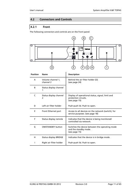
4.2.1 Front<br />
The following connectors and controls are on the front panel:<br />
Position Name Description<br />
A Volume channel 1,<br />
channel 2<br />
Behind the air filter holder [D]<br />
(see page 24)<br />
B<br />
C<br />
Status display channel<br />
1<br />
Status display channel<br />
2<br />
Display of operational status, signal, limit and<br />
protection circuits.<br />
(see page 15)<br />
D Left air filter holder Push-push lid. Push to open.<br />
E Front Ethernet port Access to all devices on the network (switch), for<br />
service purposes. (see page 18)<br />
F Status display remote Indicates that the device is being monitored/<br />
controlled via network.<br />
G ON/STANDBY button Switches the device between the operating mode<br />
and the standby mode.<br />
(see page 15)<br />
H Status display BRIDGE Indicates that the device is in bridge mode.<br />
I Right air filter holder Push-push lid. Push to open.<br />
KLING & FREITAG GMBH © 2012 Revision 3.0 Page 11 of 65