Create successful ePaper yourself
Turn your PDF publications into a flip-book with our unique Google optimized e-Paper software.
System Amplifier K&F TOPAS<br />
User's Manual<br />
Version 3.0<br />
Released: 02.10.2013<br />
Important Information,<br />
Please Read Before Use!<br />
KLING & FREITAG GmbH<br />
Junkersstraße 14<br />
D-30179 Hannover<br />
TEL +49 (0) 511 96 99 70<br />
FAX +49 (0) 511 67 37 94<br />
www.kling-freitag.de
User's manual<br />
System Amplifier K&F TOPAS<br />
Table of contents<br />
1 Introduction 6<br />
1.1 Symbols in User's Manual 6<br />
1.2 Information about this User's Manual 6<br />
2 General Safety Instructions 7<br />
3 Product Description 8<br />
3.1 TOPAS Power Amplifier 8<br />
3.2 Concept of a Network Enabled Amplifier 8<br />
3.3 Scope of Delivery 9<br />
4 Installation and Connection 10<br />
4.1 Setup Location 10<br />
4.1.1 Rack Mounting 10<br />
4.2 Connectors and Controls 11<br />
4.2.1 Front 11<br />
4.2.2 Rear 12<br />
4.3 Mains Connector 14<br />
4.3.1 Dimensioning of Power Supply System and Cool Air Supply 14<br />
5 Configuration and Operation 15<br />
5.1 Modes of Operation 15<br />
5.1.1 Standby Mode 15<br />
5.1.2 Operating Mode 15<br />
5.1.3 Error Mode 15<br />
5.2 Configuring the Modes of Operation 15<br />
5.3 Operating Concept 16<br />
5.3.1 Displays and Controls 16<br />
5.3.2 Integrated Web Interface 17<br />
5.4 Network 18<br />
5.4.1 Ethernet Ports 18<br />
5.4.2 Network Topology 19<br />
5.4.3 IP Address Assignment 20<br />
5.4.4 Allocating the Device in the Network 21<br />
5.4.5 Programmes to Allocate mDNS Devices 21<br />
5.4.6 Network Security 21<br />
5.5 Audio Functions 21<br />
5.5.1 Audio In-, Outputs 22<br />
5.5.1.1 Analogue Inputs 22<br />
5.5.1.2 AES/EBU digital input (can be optionally activated) 22<br />
5.5.2 Connecting Speakers 22<br />
KLING & FREITAG GMBH © 2012 Revision 3.0 Page 3 of 65
User's manual<br />
System Amplifier K&F TOPAS<br />
5.5.3 Input Signal Processing 23<br />
5.5.3.1 Input Sensitivity 24<br />
5.5.3.2 Routing 24<br />
5.5.3.3 Gain Control 24<br />
5.5.3.4 Front Panel Gain Control 24<br />
5.5.3.5 Delay 25<br />
5.6 Control 26<br />
5.6.1 General Purpose Input/Output (GPIO) 26<br />
5.6.1.1 Control Inputs (GPI) 26<br />
5.6.1.2 Control Outputs (GPO) 26<br />
5.6.2 Control via the <strong>Kling</strong> & <strong>Freitag</strong> Remote Software 27<br />
5.6.3 Control via the XML Scripts 27<br />
6 Web Interface 28<br />
6.1 Menu Overview 28<br />
6.2 Web Interface Status 29<br />
6.3 Web Interface Audio 31<br />
6.3.1 Audio Settings 31<br />
6.3.2 Speaker Configuration 33<br />
6.3.3 Input Configuration 34<br />
6.4 Web Interface Setup 35<br />
6.4.1 Software Update 35<br />
6.4.2 Network Settings 37<br />
6.4.3 Device Description 38<br />
6.4.4 Password Administration 39<br />
6.4.5 Power-On Options 40<br />
6.4.6 Settings Controls 41<br />
6.4.7 Settings GPIO 42<br />
6.4.8 Backup 45<br />
6.5 Web Interface Help 46<br />
6.5.1 Help Topics 46<br />
6.5.2 Contact Address 47<br />
6.5.3 Amplifier Information 48<br />
7 Service 49<br />
7.1 Hardware 49<br />
7.1.1 Replace/Clean the Air Filters 49<br />
7.1.2 Replacing the Fuse 49<br />
7.1.3 Replacing the Backup Battery of the Real Time Clock 49<br />
7.2 Troubleshooting 50<br />
8 Technical SpecificationsTOPAS 52<br />
8.1 Amplifier 52<br />
KLING & FREITAG GMBH © 2012 Revision 3.0 Page 4 of 65
User's manual<br />
System Amplifier K&F TOPAS<br />
8.2 Signal Processing 52<br />
8.3 Dimensions and Weight 53<br />
9 Disposal 54<br />
9.1 Regulations for Disposal 54<br />
9.1.1 Germany 54<br />
9.1.2 EU, Norway, Iceland, and Liechtenstein 54<br />
9.1.3 All other Countries 54<br />
10 Certificates and declarations 55<br />
10.1 CB Test Certificate 55<br />
10.2 EC Declaration of Conformity 56<br />
11 Appendix 57<br />
11.1 Parametric Filters 57<br />
11.1.1 Bell = Bell Filter 57<br />
11.1.2 HShelv = High Shelving Filter 58<br />
11.1.3 LShelv = Low Shelving Filter 58<br />
11.1.4 HighP = High Pass Filter 61<br />
11.1.5 LowP = Low Pass Filter 61<br />
11.1.6 AP = All Pass Filter 63<br />
11.1.7 Notch = Notch Filter 63<br />
12 Notes 64<br />
KLING & FREITAG GMBH © 2012 Revision 3.0 Page 5 of 65
User's manual<br />
System Amplifier K&F TOPAS<br />
1. Introduction<br />
Thank you for your decision to buy a KLING & FREITAG product. With the purchase of a<br />
K&F TOPAS, you have acquired a device with the hightest possible quality and performance<br />
capabilities. To guarantee a trouble-free operating of the equipment and to allow your<br />
device to achieve its full potential please read the operating instructions carefully before use.<br />
As the owner of a TOPAS, you now have a versatile and highly professional tool by your side..<br />
1.1 Symbols in User's Manual<br />
This symbol indicates the possibility of life-threatening danger and a health risk for persons.<br />
Not following these instructions may result in serious health problems including potentially<br />
fatal injuries.<br />
Warning<br />
This symbol indicates a possibly dangerous situation. Not following these instructions may<br />
cause minor injuries or cause property damage.<br />
Caution<br />
This symbol gives instructions for the proper use of the described products. Not following<br />
these instructions may cause malfunctions or property damage.<br />
This symbol indicates notes that help you to handle the described products easier.<br />
Tip<br />
1.2 Information about this User's Manual<br />
© KLING & FREITAG GMBH, all rights reserved.<br />
All specifications in this manual are based on information available at the time of publishing<br />
for the features and safety guidelines of the described products.<br />
Technical specifications, measurements, weights and properties are not guaranteed.<br />
The manufacturer reserves the right to make product alterations within legal provisions as<br />
well as changes to improve product quality.<br />
All persons who use the amp must have this guide and all further information for safe<br />
operations available to them during assembly, disassembly, and use. The amp may neither<br />
be set up nor used until this manual has been read, understood and kept readily available on<br />
site.<br />
We appreciate any input with suggestions and improvements for this manual. Please send this<br />
to us at the following address:<br />
info@kling-freitag.de or to:<br />
KLING & FREITAG GMBH Junkersstr.14 D-30179 Hannover.<br />
Phone +49 (0) 511 96 99 70, Fax +49 (0) 511 67 37 94.<br />
KLING & FREITAG GMBH © 2012 Revision 3.0 Page 6 of 65
User's manual<br />
System Amplifier K&F TOPAS<br />
2. General Safety Instructions<br />
Power supply<br />
Warning<br />
• Before connecting to the power supply system, check if the local voltage matches the<br />
voltage marked on the device. If this is not the case, then the unit needs to be adapted<br />
by the manufacturer or an authorized service centre. Connect the device under any<br />
circumstances, to an unauthorized power supply source. This could irreparably ruin the<br />
controller.<br />
• Make sure that the power outlet supplies a ground connector, which must be<br />
connected to the device via the PE conductor of the power cord!<br />
• Power cords should be laid in such a way that they are protected against footstep<br />
damages, tensile strain and against being trapped.<br />
• The power plug must always be used to disconnect from the power supply.<br />
• Furthermore, the power plug must be easily accessible for use at all times.<br />
• All equipment, which is connected together using signal cables and has a connection to<br />
protective earth, must be connected to a common PE conductor. If not, there is a risk of<br />
an electric shock or the destruction of the connected equipment.<br />
• The built-in lithium battery must be replaced by qualified personnel only.<br />
Connections<br />
Warning<br />
• There is a risk of electric shock or damage of the device if you connect an output with<br />
protective ground, an input or to another output!<br />
• According to the EMC directive, always use proper shielded cables with appropriate<br />
connectors.<br />
• There's risk of fire, if the speaker cables don't correspond to the amplfier's output<br />
power capabilities!<br />
• This device is not designed for home use.<br />
Maintenance and technical service<br />
Caution<br />
The user should not perform any maintenance work on the equipment other than that which<br />
is described in this manual. Repairs have to be executed by a qualified service technician only.<br />
In the following cases, the device should be serviced by an authorized technician only if:<br />
• the power cord or the mains connector have been damaged.<br />
• objects or liquids have gotten into the device.<br />
• it was exposed to rain.<br />
• the device doesn't appear to be functioning properly.<br />
• it has fallen down or the enclosure is damaged.<br />
Do not install devices in any of the following places:<br />
• where the units are permanently exposed to direct sunlight.<br />
Caution<br />
• near other heat sources or open fire.<br />
• where the airflow for cooling is blocked.<br />
• where the devices are exposed to high moisture.<br />
• where the devices are exposed to strong vibrations and dust.<br />
KLING & FREITAG GMBH © 2012 Revision 3.0 Page 7 of 65
User's manual<br />
System Amplifier K&F TOPAS<br />
Intrusion of liquids<br />
• No objects or liquids should intrude or leak into the equipment.<br />
Caution<br />
Protecting the Speakers / Operating Safety<br />
To prevent speaker damage, only connect the speaker cables when no signal is present on<br />
the outputs.<br />
Unwanted interference<br />
RF interference on the power cord or on the line signal cables may lead to unwanted sound<br />
interference.<br />
In the case your are using the optional AES/EBU input, it is possible that a complete drop out<br />
of the audio signal is possible caused by strong electromagnetic interference . This may not<br />
be announced, like anaolg signals, by audible disturbances.<br />
Pauses in use<br />
The power cord should be disconnected from the power source during longer pauses in use.<br />
Cleaning<br />
The equipment should only be cleaned with a damp cloth when it is not plugged in.<br />
Transportation<br />
When transporting the device, make sure that it is protected from vibrations.<br />
3. Product Description<br />
3.1 TOPAS Power Amplifier<br />
The TOPAS is a network-capable, dual-channel DSP amplifier for fixed installations. The DSP-<br />
Amplifier was specially designed for optimal operation with <strong>Kling</strong> & <strong>Freitag</strong> loudspeakers. It is<br />
also possible for use with other speaker systems.<br />
Via Ethernet, the TOPAS can be highly variably switched on and off, controlled and<br />
monitored. The four General Pupose Inputs (GPIs) allow you to adjust volume (digital VCA),<br />
switch on/off the amplifier. mute the channels and switch the inputs of the audio signal.<br />
You can assign events to the outputs such as amplifier status, mute status of the channels or<br />
PRIO audio activity via the web interface. Two open collector outputs and a potential free<br />
relay contact are available.<br />
Further features include the integrated web server for concise configuration, easy location of<br />
all devices in the network using AutoIP/mDNS, and the configurable access control with user/<br />
password. The TOPAS can be operated remotely, no matter which operating system is used.<br />
Because of the redundant firmware, updates are save and easy.<br />
The standby power consumption is limited to 4.5 watts. The amplifier is ready to operate<br />
within a few seconds after power on. The activation can be set via a signal over GPI, ethernet<br />
or by pressing the front button.<br />
The TOPAS allows you to monitor the internal protection circuits (Clipping, DC, short circuit,<br />
temperature, voltage) via the web interface or soon, over a remote application. Permanent<br />
monitoring of the processor via watchdog and load monitoring of the connected speakers in<br />
the future is guaranteed. All events can be monitored via web interface or GPIO.<br />
The functionality, performance capability, and expandability of the TOPAS ensure you a high<br />
planning and investment reliability.<br />
3.2 Concept of a Network Enabled Amplifier<br />
The TOPAS was developed to enable the highest possible operating safety of an entire sound<br />
system. In the future, it offers not only speaker-specific pre-amplifier control functions such as<br />
equalisation and limiters, but also further functions, such as:<br />
KLING & FREITAG GMBH © 2012 Revision 3.0 Page 8 of 65
User's manual<br />
System Amplifier K&F TOPAS<br />
• permanent status monitoring of the processor<br />
• continuous load-monitoring in order to monitor the connected speakers,<br />
The amplifier is, therefore, an intelligent device for the monitored channels.<br />
If the amplifier is used in a multi-channel installation, the status information of the amplifiers<br />
must be provided to a central control unit. This device can be a media control system,<br />
a computer, or a simple display on a control console. For this networking with other<br />
components of the given control infrastructure, several interfaces are available:<br />
• analogue interfaces (GPIO) in 0-10V and open collector technology<br />
• Ethernet ports<br />
The Ethernet ports offer:<br />
• access to the configuration via the integrated web interface<br />
• monitoring of several amplifiers using the <strong>Kling</strong> & <strong>Freitag</strong> remote software, which will<br />
be available at a later date<br />
• HTTP/XML interface for controlling via XML-Post/Request media control units<br />
To enable an affordable and powerful networking with standard components, the device<br />
has a 10/100Mb Ethernet adapter. An integrated switch provides two rear mounted Ethernet<br />
ports for connecting several devices. Additionally, there is a front port for service purposes.<br />
When using a configurable Ethernet switch (RSTP Switch) (Rapid Spanning Tree Protocol), you<br />
can also setup redundant ring networks.<br />
Locating the device in the network is also possible without knowing an IP address using the<br />
standardised ZeroConf/AutoIP protocols.<br />
3.3 Scope of Delivery<br />
The following is included in delivery:<br />
• 1 x Device <strong>Kling</strong> & <strong>Freitag</strong> TOPAS<br />
• 1 x PowerCon mains power cable<br />
• 2 x Terminal block 9 x 3.84mm (for GPI, audio)<br />
• 1 x Terminal block 4 x 5mm (speaker out)<br />
• 1 x Admin-password label<br />
• 1 x Printed user's manual with safety instructions<br />
Please note that the mains cables are delivered with varying connector options or with open<br />
wires (mains side), depending on the country or order number.<br />
KLING & FREITAG GMBH © 2012 Revision 3.0 Page 9 of 65
User's manual<br />
System Amplifier K&F TOPAS<br />
4. Installation and Connection<br />
4.1 Setup Location<br />
The TOPAS should be installed in a dust free environment, if possible.<br />
Condensation water might damage the device.<br />
Warning<br />
As you unpack the device, note the difference between the amplifier and ambient<br />
temperature. At a high temperature difference, you have to wait a sufficiently long time<br />
before you take the device out of plastic wrap.<br />
The humidity should not exceed 80%.<br />
The ambient operating temperature should not exceed 40°C (see page 14). If necessary,<br />
cool the environment of the location with suitable equipment. If the TOPAS overheats, it<br />
automatically switches to the error mode.<br />
From 95°C operating temperature of the TOPAS volume controls automatically shut down by<br />
6 dB.<br />
To avoid overheating, do not adjust the volume somewhere else in the audio system. The<br />
device would automatically switch to the error mode and should be cooled down and reset<br />
for subsequent operation.<br />
Caution<br />
Do not install devices in any of the following places:<br />
• where the devices are permanently exposed to direct sunlight.<br />
• near other heat sources or open fire.<br />
• where the airflow for cooling is blocked.<br />
• where the devices are exposed to high moisture.<br />
• where the devices are exposed to strong vibrations and dust.<br />
Do not put liquids on or near the device.<br />
4.1.1 Rack Mounting<br />
The TOPAS is intended to be mounted in 19” racks. It requires two rack units (88mm) with an<br />
installation depth of 455mm.<br />
When mounting the amplifier in the rack, ensure adequate ventilation in front of and behind<br />
it. The cooling air is taken in through the front and the heated air is rejected out the back.<br />
Ensure that the TOPAS is safely mounted in the rack. Fasten the device on the front (rack<br />
bars) and on the back with four adequately dimensioned screws each.<br />
The vents may not be blocked or closed.<br />
KLING & FREITAG GMBH © 2012 Revision 3.0 Page 10 of 65
User's manual<br />
System Amplifier K&F TOPAS<br />
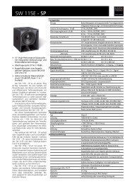
4.2 Connectors and Controls<br />
4.2.1 Front<br />
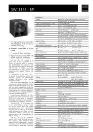
The following connectors and controls are on the front panel:<br />
Position Name Description<br />
A Volume channel 1,<br />
channel 2<br />
Behind the air filter holder [D]<br />
(see page 24)<br />
B<br />
C<br />
Status display channel<br />
1<br />
Status display channel<br />
2<br />
Display of operational status, signal, limit and<br />
protection circuits.<br />
(see page 15)<br />
D Left air filter holder Push-push lid. Push to open.<br />
E Front Ethernet port Access to all devices on the network (switch), for<br />
service purposes. (see page 18)<br />
F Status display remote Indicates that the device is being monitored/<br />
controlled via network.<br />
G ON/STANDBY button Switches the device between the operating mode<br />
and the standby mode.<br />
(see page 15)<br />
H Status display BRIDGE Indicates that the device is in bridge mode.<br />
I Right air filter holder Push-push lid. Push to open.<br />
KLING & FREITAG GMBH © 2012 Revision 3.0 Page 11 of 65
User's manual<br />
System Amplifier K&F TOPAS<br />
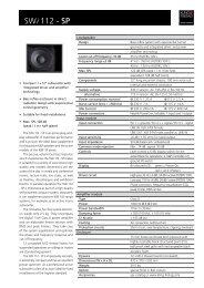
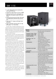
4.2.2 Rear<br />
On the rear panel are the following connections:<br />
Position Name Description<br />
A<br />
B<br />
C<br />
D<br />
E<br />
Input, link for<br />
digital audio signals<br />
according to AES/EBU<br />
Terminal connector<br />
for GPI and GPO<br />
Terminal connector<br />
for analogue audio<br />
inputs 1, 2 and<br />
priority input<br />
Analog audio input<br />
for channel 2<br />
Analog audio input<br />
for channel 1<br />
This interface can be optionally activated. Please<br />
contact your dealer to unlock the AES/EBU interface<br />
with a password.<br />
XLR, pin assignment 1=ground, 2=+, 3=-<br />
110 ohms cables are recommended.<br />
Please see chapter 5.4.1.<br />
Please see chapter 5.5.<br />
Suitable connectors:<br />
9 pin terminal block, 3.81mm grid<br />
e.g. Phoenix Contact order no. 1803646 or 1748040,<br />
Würth order no. 691 361 300 009<br />
Mating Connectors: 9 pin<br />
terminal block, pitch 3.81mm<br />
eg Phoenix Contact No. 1803646 or 1748040,<br />
Würth Art 691 361 300 009<br />
XLR Pin 1=ground, 2=+, 3=-<br />
Please note chapter 5.4.1.<br />
F Name plate Serial number, MAC address, exact device name<br />
G Ethernet ports Access to the network.<br />
All connections are equal.<br />
RJ45 IEEE 802.1<br />
10/100Mbps, half-or full-duplex (auto), auto<br />
detection of the polarity (no crossover cable<br />
required).<br />
CAT5 or higher recommended.<br />
Please note chapter 5.3.<br />
KLING & FREITAG GMBH © 2012 Revision 3.0 Page 12 of 65
User's manual<br />
System Amplifier K&F TOPAS<br />
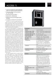
Position Name Description<br />
H Speaker outputs Neutrik Speakon (R)<br />
Pin Output1: CH1 = 1+/1-, CH2 = 2+/2-<br />
Pin Output2: CH2 = 1+/1-, CH1 = 2+/2-<br />
terminal block<br />
CH2+ CH2- CH1+ CH1-<br />
Matching plug connector<br />
Terminal block 4 pin, male (reversed), 5.08mm<br />
eg Phoenix Contact No. 1786190,<br />
Würth Art 691 348 500 004<br />
I Mains Connector Powercon Neutrik (R)<br />
The nominal voltage and rated current of the<br />
device.<br />
KLING & FREITAG GMBH © 2012 Revision 3.0 Page 13 of 65
User's manual<br />
System Amplifier K&F TOPAS<br />
4.3 Mains Connector<br />
Power supply<br />
Caution<br />
Before connecting to the power supply system, check if the local voltage matches the voltage<br />
marked on the device. Connect the device under any circumstances, to an unauthorized<br />
power supply source. This could irreparably ruin the device. The device then needs to be<br />
adapted to the required mains voltage by <strong>Kling</strong> & <strong>Freitag</strong> or an authorized service centre.<br />
Make sure that the power outlet supplies a ground connector, which must be connected to<br />
the device via the PE conductor of the power cord!<br />
All equipment, which is connected together using signal cables and has a connection to<br />
protective earth, must be connected to a common PE conductor. If not, there is a risk of an<br />
electric shock or the destruction of the connected equipment. The power plug must always<br />
be used to disconnect from the power supply. Furthermore, the power plug must be easily<br />
accessible for use at all times.<br />
Protection of electrical cables<br />
Power cords should be laid in such a way that they are protected against footstep damages,<br />
tensile strain and against being trapped.<br />
Pay attention to the stated mains voltage under the mains connector. Connection to an<br />
incorrect mains voltage may result in irreparable damage!<br />
After connecting the device to the mains supply (power supply start-up), undefined voltages<br />
may occur at the GPO connectors for approx. 50ms.<br />
In order to deactivate the device completely, you have to disconnect it from the mains<br />
voltage completely.<br />
4.3.1 Dimensioning of Power Supply System and Cool Air Supply<br />
To determine the power consumption in the operating mode - with active power amplifier<br />
section - you must know the rated power of the connected speakers. The average efficiency<br />
of the TOPAS is 65%.<br />
You can estimate the maximum input power based on the peak output of the connected<br />
speakers. The best performance is ensured when the power supply provides the 1.5 fold of<br />
the sum of the peak output of all connected speakers.<br />
If you want to switch on all amplifiers simultaneously, you must observe the inrush current<br />
of 7A. Take advantage of the delay to avoid in order to sequentially turn on the connected<br />
devices and an overload of the power supply system. (see page 40)<br />
To calculate the TOPAS' average heat emission at rated output, multiply the rated power of<br />
the connected speakers by 0.5.<br />
Example:<br />
10 CA1001 in use (5 TOPAS)<br />
CA1001 250W rated power, 500W programme power<br />
Power consumption 10 x 500W x 1.5 = 7500W<br />
Heat: 10 x 250W x 0.5 = 1250W<br />
Design and calculate the installation allowing for a reserve in the waste heat capacity.<br />
When calculating, also take other heat sources near the device into consideration.<br />
KLING & FREITAG GMBH © 2012 Revision 3.0 Page 14 of 65
User's manual<br />
System Amplifier K&F TOPAS<br />
5. Configuration and Operation<br />
5.1 Modes of Operation<br />
The device has three modes of operation:<br />
• the standby mode,<br />
• the operating mode,<br />
• the error mode.<br />
5.1.1 Standby Mode<br />
After you have connected the TOPAS to the power supply, the device switches into standby<br />
mode as a factory setting.<br />
The main power supply and the audio signal processing are deactivated. The network and<br />
the control elements are still available when the device is in the standby mode. The standby<br />
power consumption is less than 5W.<br />
If you want the amplifier to start up in the operating mode after being switched on, you can<br />
change this in the web interface (see page 40). This can be useful when the amplifier once<br />
again comes back to life after a power failure and the device should automatically switch to<br />
operating mode.<br />
5.1.2 Operating Mode<br />
Different events can trigger the amplifier to switch to the operating mode 'ON' (ready for<br />
operation). The operating status is visually indicated on both channels by illuminating the top<br />
status indicators (LEDs). (see page 11 - Pos.B / C)<br />
The amplifier is ready to operate within a few seconds after power on.<br />
5.1.3 Error Mode<br />
The amplifier switches to the error mode when there are serious errors.<br />
The main power supply is switched off in the error mode.<br />
If you are able to determine that external error influences (such as short circuits, etc.) and<br />
you can correct it, you can reset the amplifier on the power button or on the web interface.<br />
Caution<br />
Please contact your dealer.<br />
To determine the actual source for the shut-down due to an error, <strong>Kling</strong> & <strong>Freitag</strong> has to<br />
examine the device. To have this done, you must send it in. (see manufacturer address on<br />
page 6) Ask your dealer.<br />
5.2 Configuring the Modes of Operation<br />
With the following actions, you can switch between the standby and the operating modes:<br />
• push the front button,<br />
• via web interface,<br />
• impulse via GPI,<br />
• command via XML/Remote.<br />
When the TOPAS is connected to a power supply, it automatically switches to the standby<br />
mode. If you want the amplifier to switch to the operating mode after being connected to<br />
the power supply, you can change this in the web interface (see page 40).<br />
KLING & FREITAG GMBH © 2012 Revision 3.0 Page 15 of 65
User's manual<br />
System Amplifier K&F TOPAS<br />
The amplifier is equipped with a thermal inrush current limiter. To prevent an excessively<br />
high inrush current when quickly switching between operating and standby modes, the<br />
device has a power-on delay (which is integrated into the firmware) of approx. 10 seconds.<br />
You can configure the power-on events in the web interface under the menu item Setup »<br />
on/standby.<br />
5.3 Operating Concept<br />
The TOPAS is a network-capable, dual-channel DSP amplifier for fixed installations. The unit<br />
has a variety of functions and settings that are too complex for a standard display. This is why<br />
we do without such a display. You can comfortably control and monitor the device with the<br />
integrated web interface via Ethernet (remote or XML), GPIO's, or with the remote software<br />
that will be available at a later date.<br />
You can find general instructions for using the web interface in the chapter Integrated<br />
Web Interface (page 17). Information for configuration is in the respective function<br />
descriptions.<br />
For the most important parameter requests (on/standby, volume control) are in addition to<br />
the web interface controls and status displays on the device.<br />
5.3.1 Displays and Controls<br />
Position Name Description<br />
A Volume channel 1 Gain control channel 1<br />
B Volume channel 2 Gain control channel 2<br />
C Channel Ready LED If the corresponding amplifier channel is ready<br />
for operation, this status display (LED) green. This<br />
display is also available for channel 2.<br />
KLING & FREITAG GMBH © 2012 Revision 3.0 Page 16 of 65
User's manual<br />
System Amplifier K&F TOPAS<br />
Position Name Description<br />
D Channel Protect LED This LED indicates an error in the corresponding<br />
channel. It can be triggered by an active protection<br />
circuit or an over temperature failure in the<br />
channel.<br />
E Signal LED The signal LEDs will light up green if the input<br />
signal level is greater than -40dB.<br />
F Limit LED This LED lights up red when the output level of the<br />
relevant channel comes under the influence of a<br />
limiting circuit. This can be the peak limiter or the<br />
RMS limiter of the speaker block.<br />
G Remote LED Indicates that the unit is being monitored or<br />
controlled via a network connection.<br />
H<br />
ON/STANDBY button<br />
with status display<br />
You can switch between the ON and the STANDBY<br />
mode by pushing this button. The integrated LED<br />
lights up yellow when the device is in standby<br />
mode. In ON mode, the LED is green.<br />
I Bridge LED Indicates that the amplifier is operating in bridged<br />
mode.<br />
5.3.2 Integrated Web Interface<br />
To enable fast, safe, and clearly arranged use of the TOPAS, we integrated a highperformance<br />
web interface instead of a display. This not only allows you to configure the<br />
device from any place in the network, but you can also monitor and update it.<br />
For you to have monitoring and controlling to the amplifier via the web interface, the<br />
following requirements must be fulfilled:<br />
• An ethernet-capable computer is connected to the TOPAS network. Please refer to the<br />
chapter network (see page 18).<br />
• On this ethernet-capable computer is a service for finding Zeroconf / mDNS enabled<br />
devices exist or the IP of the TOPAS is known. (see page 21)<br />
KLING & FREITAG GMBH © 2012 Revision 3.0 Page 17 of 65
User's manual<br />
System Amplifier K&F TOPAS<br />
Start your browser by selecting the device in the mDNS service or enter the IP address directly<br />
into the browser address bar.<br />
Please note that the access to some functions can be limited due to different access rights.<br />
You can set the passwords for the access rights in the web interface (see page 39).<br />
In the first password request of the TOPAS please fill in the fields:<br />
• Username: master<br />
• Password: master<br />
You should change the passwords entered by the manufacturer in the web interface. (see<br />
page 39)<br />
Tip<br />
Now you can use all functions of the amplifier. You will find detailed descriptions of the<br />
individual functions in the following chapters. You can open the individual function menus<br />
using the navigation bar of the web interface. An overview of all configuration pages is in<br />
the following chapter.<br />
In the web interface, there is integrated help available for some of the device's functions. You<br />
can find it in the menu item 'Help'.<br />
5.4 Network<br />
5.4.1 Ethernet Ports<br />
The TOPAS has three RJ45 Ethernet ports. Two are on the back of the device. The interfaces<br />
are connected to one another and with the DSP unit via an internal switch. All ports have the<br />
same priority.<br />
The ports recognize the connected device automatically. Speeds of 10/100Mbit/s, half or fullduplex<br />
as well as polarity recognition are supported. The use of crossover cables or adapters<br />
is not necessary, but possible.<br />
KLING & FREITAG GMBH © 2012 Revision 3.0 Page 18 of 65
User's manual<br />
System Amplifier K&F TOPAS<br />
5.4.2 Network Topology<br />
Depending on the demands on the system stability of the network, you can setup different<br />
network topologies.<br />
If you want to setup a ring topology with Ethernet networks, switches are necessary to<br />
enable flexible adjustment of the routings. Otherwise, collisions and packet loss can occur<br />
because of data packages circling in the ring topology. All mechanisms necessary for<br />
administering ring topologies and for quickly switching to alternate routes if there is an error<br />
in a branch of the network are standardised as '(Rapid-) Spanning-Tree' protocols and are<br />
supported by many managed switches.<br />
Depending on the safety demands of the usage, we recommend the following network<br />
topologies:<br />
1. Daisy-Chaining (no redundancy)<br />
Daisy chaining is the simplest way to network several amplifiers. In this case, no external<br />
switch aside from the integrated switches is necessary.<br />
Please ensure that all amplifiers are connected to the electric circuit. Otherwise, the<br />
network signals cannot be passed on via the integrated switch.<br />
2. Star (Malfunction of several amplifiers, large unmanaged switch)<br />
KLING & FREITAG GMBH © 2012 Revision 3.0 Page 19 of 65
User's manual<br />
System Amplifier K&F TOPAS<br />
Using a non-configurable switch with a sufficient number of ports guarantees the<br />
stability of the system even if several amplifiers fail. If the switch malfunctions, you<br />
cannot reach any amplifier.<br />
3. Simple Redundancy: Malfunction of one amplifier, small managed switch<br />
If two ports of a managed switch are available, you can set up a simple ring. You must<br />
configure the switch accordingly. By doing this, even if one device malfunctions, all others<br />
are reachable. If the switch malfunctions, you cannot reach any amplifier.<br />
Please ensure that all amplifiers are connected to the electric circuit. Otherwise, the<br />
network signals cannot be passed on via the integrated switch.<br />
4. Multiple Redundancy with Switch, two large switches (managed)<br />
Double star-shaped cabling with two configurable sufficiently sized switches provides<br />
operating safety if one switch and any number of amplifiers fail.<br />
The TOPAS' controller (DSP/network) is equipped with its own power supply unit that<br />
is independent of the main power supply. This ensures safe operations of the network<br />
connections even if the main power supply fails (overload, overheating).<br />
KLING & FREITAG GMBH © 2012 Revision 3.0 Page 20 of 65
User's manual<br />
System Amplifier K&F TOPAS<br />
5.4.3 IP Address Assignment<br />
Upon delivery, all devices are set to have a sequential address assignment. If no DHCP server<br />
can provide an IP address, the address is selected from the auto-IP address range. Thus, there<br />
are three possibilities to assign addresses:<br />
• Auto-IP: With this function, the device generates and requests an IP adress on its own<br />
from the IP range 169.254.1.0 to 169.254.254.255, with the subnet mask 255.255.0.0.<br />
The address ranges 169.254.0.x and 169.254.255.x are reserved and may not be set.<br />
• DHCP: A DHCP server assigns an IP address.<br />
• Static IP: The user assigns a fixed IP address.<br />
If you connect the device to the power supply first and then to a network in which a DHCP<br />
server is present, the device stays in the Auto IP range for up to six minutes before an address<br />
from the DHCP server is accessed. To avoid this waiting time, we recommend connecting the<br />
device to the network first and subsequently connecting it to the power supply.<br />
You can set the addressing mode in the web interface. (see page 37)<br />
5.4.4 Allocating the Device in the Network<br />
Independent of the selected IP addressing procedure, you can allocate the device in the<br />
network via mDNS.<br />
If not specified in the web interface mDNS name (see page 38), the amplifier generates its<br />
own mDNS name. The self-generated mDNS name is made up of type and serial number.<br />
For a detailed description see chapter Integrated Web Interface on page 17.<br />
5.4.5 Programmes to Allocate mDNS Devices<br />
If you want to access the web interface without a known IP address, one of the following<br />
programmes must be installed on your computer:<br />
• STG ZeroConf Explorer: http://www.stg.com/zeroconf_explorer.html<br />
• Apple Bonjour: http://support.apple.com/downloads/DL999/en_EN/BonjourPSSetup.exe<br />
with Bonjour Foxy Firefox add-on: http://dnssd.me/<br />
• Apple's Safari browser with built-in Bonjour, with installed Apple's Bonjour<br />
On Apple computers, Bonjour is already installed.<br />
5.4.6 Network Security<br />
To prevent manipulation of the connected devices, you should follow basic security rules in<br />
handling networks. The communication via the used protocol 'http' generally takes place<br />
unencrypted so that attackers can intercept and see transferred data.<br />
Preventive measures:<br />
• The devices must be in a closed network area that is separated by a firewall/router.<br />
This can be a separate network hardware or a sub-network within an existing network<br />
infrastructure.<br />
• Remote access into this network may only be done via a safe, strongly encrypted<br />
connection (VPN).<br />
• If some parts of the network connection run as a wireless network (WLAN), you must<br />
secure this with a strong encryption method (i.e. WPA2 with AES/TKIP), since the<br />
communication between the devices can otherwise be tapped by packet sniffing.<br />
• You must prevent unauthorised persons from gaining direct access to network ports<br />
(cables).<br />
• The devices' user passwords must not be trivial or easy to guess.<br />
KLING & FREITAG GMBH © 2012 Revision 3.0 Page 21 of 65
User's manual<br />
System Amplifier K&F TOPAS<br />
5.5 Audio Functions<br />
5.5.1 Audio In-, Outputs<br />
5.5.1.1 Analogue Inputs<br />
Three symmetrical inputs (Channel 1, Channel 2, PRIO) are available to you. Channels 1<br />
and 2 are designed as XLR connectors [illus. C, D] with a link connector and as a clamp<br />
connector [illus. B]; the priority input is implemented as a clamp connector only [illus. A].<br />
Input sensitivity and routing can be switched (see chapter Input Sensitivity on page [24]).<br />
All analogue inputs of a channel are internally connected to one another in parallel.<br />
5.5.1.2 AES/EBU digital input (can be optionally activated)<br />
In order to apply digital audio signals you can activate the AES/EBU interface with a<br />
password. Please contact your dealer.<br />
Position<br />
A<br />
B<br />
Description<br />
Input for digital audio signals, balanced AES/EBU compatible.<br />
AES/EBU output, the signal is balanced and amplified internally.<br />
The XLR connectors and the AES/EBU interfaces are always mounted.<br />
In order to apply digital audio signals you can activate the AES/EBU interface with an<br />
optionally available password. Please contact your dealer.<br />
The interface supports the following data structures:<br />
• Sampling rate 44.1 - 96kHz<br />
• Word length 16, 18, 20 and 24bit<br />
The signal can be looped through to another device via the link connector. The signal is<br />
balanced and amplified internally.<br />
In newer devices, there is a hardware bypass to ensure that a subsequent device is not<br />
separated from a present signal in case there is no mains voltage.<br />
Under ideal circumstances, the maximum possible cable length for AES/EBU signals is approx.<br />
300 meters. Whether or not this cable length can actually be reached depends on the<br />
auxiliary device and the quality of the cabling.<br />
If there are problems with the transmission, it may be helpful to reduce the sampling rate.<br />
KLING & FREITAG GMBH © 2012 Revision 3.0 Page 22 of 65
User's manual<br />
System Amplifier K&F TOPAS<br />
5.5.2 Connecting Speakers<br />
Position<br />
Description<br />
A Speakon connector, CH2 = 1+/1-, CH1 = 2+/2-<br />
B Phoenix connector, CH 2 and CH 1<br />
C Speakon connector, CH1 = 1+/1-, CH2 = 2+/2-<br />
The speaker outputs are designed as Speakon and Phoenix connectors. Both outputs are<br />
available on both Speakon connectors.<br />
All outputs of a channel are electrically connected to one another in parallel.<br />
On each channel of the amplifier, you can operate a load with an impedance of at least 2<br />
ohms each.<br />
In addition to two-channel mode (Dual/Mono), the amplifier can also be switched to so-called<br />
bridge mode (Bridge). Each operating mode requires a different type of speaker connection.<br />
Bridge mode<br />
In the bridge mode, both amplifier channels are bundled to one channel. In that case the<br />
amplifier is capable of providing very high output power levels.<br />
To operate a speaker in bridge mode,<br />
• the speaker must be connected between CH1+ and CH2+ [compare to illus. LS Outputs].<br />
In this case, CH1+ is connected to the positive pin of the speaker.<br />
• the amplifier routing must be switched to 'Bridge Mode'. (see page 31)<br />
Never allow the load impedance to fall below 4 ohms in bridge mode. Otherwise, the<br />
amplifier would interpret this to be a short circuit and would shut down early.<br />
The filter settings for channel 2 are inactive.<br />
In the web interface, switching is possible in the menu item. (see page 31)<br />
KLING & FREITAG GMBH © 2012 Revision 3.0 Page 23 of 65
User's manual<br />
System Amplifier K&F TOPAS<br />
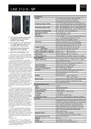
5.5.3 Input Signal Processing<br />
CH 1<br />
DSP<br />
A<br />
Output 1<br />
1+<br />
V<br />
1-<br />
CH 2<br />
A<br />
Output 2<br />
1+<br />
PRIO<br />
V<br />
1-<br />
Sensitivity<br />
Gain,<br />
filter,<br />
routing<br />
Poweramp<br />
5.5.3.1 Input Sensitivity<br />
The analogue inputs have a switchable gain to make optimal adjustments to the signal source<br />
level. This also changes the overall gain that is specified in the web interface. You can adjust<br />
the gain in the web interface in the menu item. (see page 31)<br />
To minimise the total noise level of the system, you should always use the lowest possible<br />
value at which no distortion occurs.<br />
The function 'Auto Attenuation' enables an automatic gain switching when an overload<br />
occurs.<br />
5.5.3.2 Routing<br />
You can assign any input channel (Input 1, Input 2) or the sum signal (Mono Mix) to each<br />
amplifier channel. To avoid clipping, the sum signal is attenuated by 6dB.<br />
5.5.3.3 Gain Control<br />
The gain of a channel can be set by three input ways: By entering values in 'Group Gain' and<br />
'Gain' and with the horizontal slider. (see page 31)<br />
• input sensitivity: Global for both channels (see page 24)<br />
• Gain setting of the channel: Gain in this DSP channel. The gain is individually<br />
adjustable.<br />
• Only valid for the remote software, available at a later date: Gain of the group:<br />
gain factor in this DSP channel, adjustable when assigning to a group. This value is<br />
assigned when operating via GPI, remote software or XML for gain control of a group<br />
of channels.<br />
5.5.3.4 Front Panel Gain Control<br />
You can adjust the volume of both channels with the two gain controls behind the left front<br />
panel.<br />
KLING & FREITAG GMBH © 2012 Revision 3.0 Page 24 of 65
User's manual<br />
System Amplifier K&F TOPAS<br />
In the factory setting, this volume controls are disabled.<br />
In the web interface you can enable this volume control. (see page 41)<br />
It is possible that an external control element (web interface, remote, GPI) sets the gain of<br />
a channel at a lower level than what the gain control's position indicates. In this case, you<br />
must turn down the potentiometer until the current value of the control is the same as the<br />
current gain. When you have done this, you can once again change the volume using the<br />
gain control.<br />
If you control the volume using the GPI interface, you must follow the same rules as with the<br />
gain controls on the front panel.<br />
To adjust the volume on the front panel, the gain controls must not be locked. (See page<br />
41)<br />
5.5.3.5 Delay<br />
For each channel you have a delay for time alignment of a maximum of 2000 milliseconds.<br />
Calculate the delay with the following formula:<br />
t = d / c<br />
t = time in seconds<br />
d = distance in meters<br />
c = speed of sound in m / s<br />
KLING & FREITAG GMBH © 2012 Revision 3.0 Page 25 of 65
User's manual<br />
System Amplifier K&F TOPAS<br />
5.6 Control<br />
5.6.1 General Purpose Input/Output (GPIO)<br />
The device has four control inputs (0-10V, variable) and four control outputs (switched, 5V/<br />
open collector, or in the standard configuration: two open collectors and a potential free<br />
GPO). These are located on the rear of the device as clamps (compare to illus. Clamp terminal/<br />
GPIO).<br />
You can assign functions to the control inputs and outputs via the web interface.<br />
5.6.1.1 Control Inputs (GPI)<br />
The GPIs are event driven. A new value is taken over the moment this value has been<br />
changed. When there is multiple access to an internal parameter (i.e. volume) by varying<br />
interfaces (web interface, GPI, front panel and/or remote software), the last selected value is<br />
valid, no matter from which interface it was selected.<br />
The common ground of the GPIO's is connected to the audio ground as well as to PE. During<br />
installation, make sure that you do not build up any ground loops. Transient currents in<br />
ground loops can cause malfunctions or destroy the device.<br />
The control inputs allow for the control of internal conditions with 0-10V signals. This allows<br />
for i.e. a gain control through external systems such as media control units.<br />
5.6.1.2 Control Outputs (GPO)<br />
The control outputs are open collector outputs with a separate supply voltage. This allows for<br />
two operating modes:<br />
• a) Active Mode: The device can directly supply small loads (LEDs, REED-Relais) with up to<br />
5 volts. The outputs are short-circuit-proof.<br />
• b) Open Collector Mode: External voltages of up to 50V can be switched against<br />
ground.<br />
In newer amplifiers, there is a normally open contact in the standard configuration between<br />
the GPO connectors 3 and 4. With this, only three of the four GPO's are available.<br />
A modification to include further connecting options is possible. Further alternatives include<br />
a normally closed contact between the GPO connectors 3 and 4 or four open collector<br />
outputs. For modifications, please contact your <strong>Kling</strong> & <strong>Freitag</strong> authorised dealer.<br />
KLING & FREITAG GMBH © 2012 Revision 3.0 Page 26 of 65
User's manual<br />
System Amplifier K&F TOPAS<br />
In the case you are using an external voltage source make sure that the overall current of all<br />
loads of the GPOs does not exceed 50 mA.<br />
Caution<br />
5.6.2 Control via the <strong>Kling</strong> & <strong>Freitag</strong> Remote Software<br />
To control a larger number of devices, we will offer the <strong>Kling</strong> & <strong>Freitag</strong> Remote Software in<br />
the future as a computer-based program. For further information, please contact your <strong>Kling</strong><br />
& <strong>Freitag</strong> dealer.<br />
5.6.3 Control via the XML Scripts<br />
An XML interface is available to control devices. Using this, you can control all parameters of<br />
the amplifier with, for example, network compatible media control units.<br />
Please request an interface description from your <strong>Kling</strong> & <strong>Freitag</strong> dealer.<br />
KLING & FREITAG GMBH © 2012 Revision 3.0 Page 27 of 65
User's manual<br />
System Amplifier K&F TOPAS<br />
6. Web Interface<br />
6.1 Menu Overview<br />
To enable fast, safe, and clearly arranged use of the TOPAS, we integrated a highperformance<br />
web interface instead of a display. This not only allows you to configure<br />
the device from any place in the network, but you can also monitor and update it. In this<br />
chapter, we describe how to adjust the settings and which information you get from the web<br />
interface.<br />
On the page header of every page, you can see the connection speed, the online status and<br />
the device descriptions given in 'Setup'. You will find the navigation menu in the lower part<br />
of the page header. By clicking on a menu item, you can switch between the various pages.<br />
Under a selected main menu item, a small triangle is shown. A selected subitem in the row<br />
under it is shown in bold type.<br />
Setting Submenu Function<br />
Status System Information Overview of the most important settings,<br />
switching between standby and operating<br />
mode<br />
Audio<br />
Gain, filter and delay<br />
settings management<br />
Setup<br />
Help<br />
speakers<br />
PRIO-audio<br />
updates<br />
network<br />
description<br />
users<br />
on/standby<br />
frontpanel controls<br />
gpio<br />
topics<br />
contact K&F<br />
about<br />
Speaker block assignment<br />
Managing PRIO audio settings<br />
Firmware management<br />
Management of network login procedures<br />
Specific information about the amplifier<br />
Password management<br />
Management of the unit's on/off-behaviour<br />
Enable / disable the controls on the front<br />
page.<br />
Inputs and outputs management<br />
Calculation formula, GPO diagram,<br />
explanation IP addresses<br />
K&F contact<br />
Information about firmware version and<br />
serial number of the TOPAS<br />
KLING & FREITAG GMBH © 2012 Revision 3.0 Page 28 of 65
User's manual<br />
System Amplifier K&F TOPAS<br />
6.2 Web Interface Status<br />
Menu: Status<br />
Under this menu item, the web interface shows an overview of the most important settings.<br />
System:<br />
• Location: Information that you can enter under Setup » description.<br />
• Serial-Nr.: Serial number of the TOPAS<br />
• IP-Mode: Settings you have chosen under Setup » network<br />
• Main Supply: Switches between 'standby mode' and 'operating mode'.<br />
• PRIO Audio: Switching between normal audio mode and PRIO audio mode<br />
Channel 1 – General:<br />
• Status: status notification whether channel 1 is ready for operation.<br />
KLING & FREITAG GMBH © 2012 Revision 3.0 Page 29 of 65
User's manual<br />
System Amplifier K&F TOPAS<br />
Channel 1 – Audio:<br />
• RMS-Level: Audio signal level<br />
• Limiter: status notification of the peak limiter (PK), RMS limiter (RMS) and current (CUR)<br />
• Clipping: status notification of the analogue input (ADC) and the amplifier module<br />
(AMP)<br />
Channel 1 – Cooling:<br />
• Temp: Curent working temperature<br />
• Fan: Operating status of the fans<br />
Channel 2 has the same status messages as channel 1.<br />
KLING & FREITAG GMBH © 2012 Revision 3.0 Page 30 of 65
User's manual<br />
System Amplifier K&F TOPAS<br />
6.3 Web Interface Audio<br />
6.3.1 Audio Settings<br />
Menu: Audio » gain, filter, delay<br />
Under this menu item, you adjust all audio settings.<br />
• Audio Source: Switches between 'Analog' und 'AES/EBU' inputs<br />
• Amplifier Gain with Analog Input: Selection between '39 dB', '33 dB', '27 dB', '21 dB'<br />
and activation of 'Auto Attentuation'<br />
• Bridge Mode: Switches between 'Dual Channel Mode' and 'Bridge Mode'<br />
• All Channels: toggle between 'On' (open channel) and 'mute' (channel off)<br />
KLING & FREITAG GMBH © 2012 Revision 3.0 Page 31 of 65
User's manual<br />
System Amplifier K&F TOPAS<br />
Channel 1:<br />
• RMS-Level: Audio signal level<br />
• Limiter: status notification of the peak limiter (PK), RMS limiter (RMS) and current (CUR)<br />
• Clipping: status notification of the analogue input (ADC) and the amplifier module<br />
(AMP)<br />
• Channel 1: toggle between 'On' (open channel) and 'mute' (channel off)<br />
• Input-Routing: Switches between 'Input 1', 'Input 2' and 'Monomix(-6dB)'<br />
• Delay: Input in ms, max. 2000 ms<br />
• invert Phase: invert Phase 'on' or 'off'<br />
• Gain: Enter gain in dB, this value is the volume level of the amplifier itself.<br />
The total gain of the corresponding TOPAS is the sum of 'Group Gain' and 'Gain'.<br />
• Group Gain: Enter gain in dB, this value will be specified by the remote software in the<br />
future.<br />
• Filter: Possibilities to set four free selectable filters, 'Type', 'F[Hz]', 'Q', G[dB] and<br />
activation of this setting<br />
Channel 2 has the same settings as channel 1.<br />
Further information about filters and their functionality, see page 57.<br />
KLING & FREITAG GMBH © 2012 Revision 3.0 Page 32 of 65
User's manual<br />
System Amplifier K&F TOPAS<br />
6.3.2 Speaker Configuration<br />
Menu: Audio » speakers<br />
Under this menu item, you configure the speakers.<br />
To make an optimal protection and equalisation of the attached speakers possible, special<br />
speaker blocks are available from <strong>Kling</strong> & <strong>Freitag</strong>.<br />
You choose the attached speakers the selections in the select list 'Select attached speaker'.<br />
If a selected speaker block has special filters, these are shown under 'switchable filter'. You<br />
can deactivate each of these filters.<br />
Activate an LShelv filter in the audio settings when using SEQUENZA 5 and SEQUENZA 10<br />
speakers. These filter settings depend on the number of speakers. Please refer to the relevant<br />
chart in chapter 'LShelv = Low Shelving Filter' on page 54 for SEQUENZA speaker array<br />
settings. LShelv = Low Shelving Filter58<br />
Using the parameter 'Limit Reduction', you can reduce the RMS limiter threshold and the<br />
peak level of the speakers. This allows to limit the output power to comply with noise<br />
emission standards, or the speaker to operate at reduced power for other reasons.<br />
When operating in the 'Load Monitorings' mode, you have to specify the number of<br />
speakers. In the current version of the firmware, this setting does not have any function yet.<br />
KLING & FREITAG GMBH © 2012 Revision 3.0 Page 33 of 65
User's manual<br />
System Amplifier K&F TOPAS<br />
6.3.3 Input Configuration<br />
Menu: Audio » PRIO<br />
Under this menu item, you can configure the PRIO audio mode.<br />
The PRIO audio mode serves to achieve a priority or alarm function. When the PRIO audio<br />
mode is activated, the analogue PRIO audio input (see page ...) is used as the signal source for<br />
both amplifier channels. Furthermore, the settings from the PRIO audio setup overwrite the<br />
audio settings for amplifier gain, mute, gain, delay and filter. The group gain is set to 0dB. All<br />
other audio settings like speaker settings, bridge mode and phase are not influenced.<br />
The PRIO audio mode can be activated via web interface, GPI or XML command.<br />
KLING & FREITAG GMBH © 2012 Revision 3.0 Page 34 of 65
User's manual<br />
System Amplifier K&F TOPAS<br />
6.4 Web Interface Setup<br />
Menu: Setup<br />
In this menu, you adjust all important settings on the amplifier.<br />
6.4.1 Software Update<br />
Menu: Setup » updates<br />
Under this menu item, the web interface shows more detailed information about the<br />
firmware.<br />
To update the firmware, a firmware package is required. You can get the package from your<br />
dealer.<br />
The firmware packages are digitally signed. For this amplifier model, you can only install<br />
firmware versions released by <strong>Kling</strong> & <strong>Freitag</strong>.<br />
Please pay attention to the 'Release-Notes' belonging to each update. It may be necessary<br />
to update other components or to adjust the system settings in conjunction with a firmware<br />
update.<br />
Before an update, make sure the device is connected to the power supply and in standby<br />
mode.<br />
KLING & FREITAG GMBH © 2012 Revision 3.0 Page 35 of 65
User's manual<br />
System Amplifier K&F TOPAS<br />
Under 'Sending an update package', you can send a given firmware file with the ending 'fwu'<br />
from your hard drive to the TOPAS.<br />
Choose a file under the item 'Choose a file to upload'.<br />
After opening the chosen file with 'open', the status of the upload is shown. When the<br />
update has been successful, a notification appears on the web interface.<br />
To finish the update procedure, you have to restart the TOPAS by pushing the button Reboot.<br />
If the update is interrupted, the TOPAS keeps in the current version of the firmware. To<br />
properly finish the interrupted update procedure, you have to restart the update.<br />
KLING & FREITAG GMBH © 2012 Revision 3.0 Page 36 of 65
User's manual<br />
System Amplifier K&F TOPAS<br />
6.4.2 Network Settings<br />
Menu: Setup » network<br />
Under this menu item, the web interface shows information about the network.<br />
'Current network status' shows different settings you need for network operation.<br />
In the section 'IP configuration', you determine where the TOPAS gets its IP address from.<br />
• DHCP: A DHCP server assigns an IP address.<br />
• Auto IP: With this function, the device generates and requests an IP address on its own<br />
from the IP range 169.254.1.1 to 169.254.254.255, with the subnet mask 255.255.0.0.<br />
• Static IP: The user assigns a fixed IP address.<br />
Make sure that your network setting of the client (the device with which you access the<br />
amplifier) is the same as the amplifier's settings. If you change and confirm the amplifier's IP<br />
mode, the IP address can change inadvertently, thus blocking your access to the amplifier via<br />
the client. In this case, you have to adjust the client's settings to change the IP address on the<br />
amplifier. (see page 50)<br />
KLING & FREITAG GMBH © 2012 Revision 3.0 Page 37 of 65
User's manual<br />
System Amplifier K&F TOPAS<br />
6.4.3 Device Description<br />
Menu: Setup » description<br />
Under this menu item, you can file more specific information about the amplifier.<br />
To make it easier to identify multiple devices in the network, you can freely assign individual<br />
devices with text names. You can give the devices distinct names and enter the exact location,<br />
owner, and service contact addresses.<br />
If you do not have a mDNS name the amplifier generates its own. The self-generated mDNS<br />
name is made up of type and serial number.<br />
KLING & FREITAG GMBH © 2012 Revision 3.0 Page 38 of 65
User's manual<br />
System Amplifier K&F TOPAS<br />
6.4.4 Password Administration<br />
Menu: Setup » users<br />
Under this menu item, you define the passwords for the users of the amplifier.<br />
You can define the passwords for the following user groups:<br />
• Master: The 'Master' can look and change all settings for the amplifier.<br />
• Technician: The 'Technician' can switch the amplifier on and off and can change the<br />
audio settings in the web interface.<br />
• Viewer: As a 'Viewer' your are allowed to monitor most of the parameters. But you<br />
can't change the setup.<br />
Admin: In the case you have forgotten your master-password, it is possible to get access to<br />
all functions of the web interface as the 'admin' and his admin-password too. The adminpassword<br />
is part of the delivery scope as a sticker. In the case you lost this sticker too, you<br />
can ask for your admin-password at <strong>Kling</strong> & <strong>Freitag</strong> (see address). Have your serial-number of<br />
your TOPAS ready.<br />
KLING & FREITAG GMBH © 2012 Revision 3.0 Page 39 of 65
User's manual<br />
System Amplifier K&F TOPAS<br />
6.4.5 Power-On Options<br />
Menu: Setup » on/standby<br />
Under this menu item, you define the delay time for power on as well as the operating mode<br />
after connecting to the power supply.<br />
In the setting 'Delay time for switching main supply on', the delay time that the amplifier<br />
waits before switching from standby mode to operating mode is in milliseconds.<br />
If you want to switch on several devices simultaneously using one common switch, you must<br />
not exceed an inrush current of 7A to avoid overloading the mains. With this setting, you<br />
avoid an overload.<br />
With the option 'After AC powerloss', you determine if the amplifier should be in operating<br />
mode after connection to the power supply.<br />
This can be useful when the amplifier once again comes back to life after a power failure and<br />
the device should automatically switch to operating mode.<br />
KLING & FREITAG GMBH © 2012 Revision 3.0 Page 40 of 65
User's manual<br />
System Amplifier K&F TOPAS<br />
6.4.6 Settings Controls<br />
Menu: Setup » frontpanel controls<br />
Under this menu item, you select the function of the front button and the volume controls<br />
behind the left front panel of the amplifier.<br />
To prevent unauthorised persons from using the device, you can limit the function of the<br />
controls on the front of the device by default.<br />
Possible settings are:<br />
Power On/Standby Button (on / standby front button)<br />
• disabled<br />
• enabled<br />
• wake up only<br />
• send to standby only<br />
Volume control:<br />
• disabled<br />
• enabled<br />
If you activate the volume knob, you can change the settings as desired via the front<br />
controller.<br />
KLING & FREITAG GMBH © 2012 Revision 3.0 Page 41 of 65
User's manual<br />
System Amplifier K&F TOPAS<br />
6.4.7 Settings GPIO<br />
Menu: Setup » gpio<br />
Under this menu item, you make the settings on the GPIO's.<br />
Control Outputs (GPO)<br />
After connecting the device to the mains supply (power supply start-up), undefined voltages<br />
may occur at the GPO connectors for approx. 50ms.<br />
The current at the output during open collector configuration must not exceed 250 mA.<br />
Please calculate the series resistor accordingly. If this current is exceeded, the device can be<br />
damaged.<br />
KLING & FREITAG GMBH © 2012 Revision 3.0 Page 42 of 65
User's manual<br />
System Amplifier K&F TOPAS<br />
You can select the following options for every GPO:<br />
Setting Option Description<br />
always<br />
power on<br />
system ready<br />
Mute CH1<br />
Mute CH2<br />
Mute CH1+2<br />
AES-EBU/<br />
Analog<br />
PRIO-audio<br />
Please note:<br />
low / open<br />
high / closed<br />
low / open<br />
high / closed<br />
low / open<br />
high / closed<br />
low / open<br />
high / closed<br />
low / open<br />
high / closed<br />
low / open<br />
high / closed<br />
low / open<br />
high / closed<br />
low / open<br />
high / closed<br />
always 0V<br />
always 5V<br />
0 V, switched on amplifier<br />
5 V, switched on amplifier<br />
0 V, switched on amplifier signal paths ready for<br />
operation<br />
5 V, switched on amplifier signal paths ready for<br />
operation<br />
0 V, when channel 1 is muted<br />
5 V, when channel 1 is muted<br />
0 V, when channel 2 is muted<br />
5 V, when channel 2 is muted<br />
0 V, when channel 1 and 2 are muted<br />
5 V, when channel 1 and 2 are muted<br />
AES/EBU input is activated, otherwise analog input<br />
AES/EBU input is activated, otherwise analog input<br />
PRIO audio mode is activated<br />
PRIO audio mode is activated<br />
• at low/open the contact is always open<br />
• bei high/close ist der Kontakt immer geschlossen<br />
KLING & FREITAG GMBH © 2012 Revision 3.0 Page 43 of 65
User's manual<br />
System Amplifier K&F TOPAS<br />
Control Inputs (GPI)<br />
You can select the following options for every GPI:<br />
Setting<br />
Description<br />
disabled<br />
without function<br />
Button action<br />
Button<br />
Power OFF<br />
Pushing the button switches the amplifier off.<br />
Power ON<br />
Pushing the button switches the amplifier on.<br />
Power Toggle<br />
Pushing the button switches the amplifier on or<br />
off.<br />
0-10 V functions (0-10 V)<br />
0-10V<br />
Functions<br />
Gain CH1<br />
The volume level of channel 1 is proportional to<br />
the input voltage.<br />
Gain CH2<br />
The volume level of channel 2 is proportional to<br />
the input voltage.<br />
Gain<br />
CH1+CH2<br />
The volume levels of channel 1 and 2 is<br />
proportional to the input voltage.<br />
Switching functions (Switch (ON/OFF))<br />
Switch<br />
Mute CH1<br />
If a switch is closed, channel 1 is muted.<br />
Mute CH2<br />
If a switch is closed, channel 2 is muted.<br />
Mute CH1+2<br />
If a switch is closed, channel 1 and 2 are muted.<br />
AES-EBU/<br />
Analog<br />
If a switch is closed, the AES/EBU input is activated.<br />
PRIO Audio<br />
If a switch is closed, the PRIO audio mode is<br />
activated.<br />
The setting 'invert Logic' inverts the logic of the corresponding GPI.<br />
Voltages above 12V are not allowed and will be discharged to ground.<br />
KLING & FREITAG GMBH © 2012 Revision 3.0 Page 44 of 65
User's manual<br />
System Amplifier K&F TOPAS<br />
6.4.8 Backup<br />
Menu: Setup » backup<br />
Under this menu item, you can export various setting into a XML format.<br />
With the current firmware, the exported XML file is only suitable for documentation.<br />
You can export the following TOPAS settings as XML files:<br />
• Device-Setup:, network setting, device description, user settings, device mode, selected<br />
function of the Power On/Standby pushbutton, GPIO settings<br />
• audio setup: gain/filter/delay settings, speaker settings<br />
After you have selected the desired dataset, the corresponding XML file is shown in the<br />
browser. You then have the following possibilities:<br />
• You can save the page using the context menu of your browser,<br />
• You can save the target using the context menu of your browser,<br />
• You can select the entire text, and cut or copy and paste it into a suitable programme.<br />
Then you must save the newly created file.<br />
KLING & FREITAG GMBH © 2012 Revision 3.0 Page 45 of 65
User's manual<br />
System Amplifier K&F TOPAS<br />
6.5 Web Interface Help<br />
The help texts are under this menu item.<br />
6.5.1 Help Topics<br />
Menu: Help » topics<br />
The web interface displays various help texts under this menu item.<br />
KLING & FREITAG GMBH © 2012 Revision 3.0 Page 46 of 65
User's manual<br />
System Amplifier K&F TOPAS<br />
6.5.2 Contact Address<br />
Menu: Help » contact K&F<br />
The web interface shows the contact information for <strong>Kling</strong> & <strong>Freitag</strong> under this menu item.<br />
KLING & FREITAG GMBH © 2012 Revision 3.0 Page 47 of 65
User's manual<br />
System Amplifier K&F TOPAS<br />
6.5.3 Amplifier Information<br />
Menu: Help » about<br />
The web interface shows the firmware's current version number and the amplifier's serial<br />
number.<br />
KLING & FREITAG GMBH © 2012 Revision 3.0 Page 48 of 65
User's manual<br />
System Amplifier K&F TOPAS<br />
7. Service<br />
7.1 Hardware<br />
7.1.1 Replace/Clean the Air Filters<br />
The device is equipped with three fans and air filters. To clean the air filters, remove both<br />
front panel lids and take out the air filter elements. Remove any dust by tapping on the filter<br />
or blowing the dust out.<br />
If you cannot clean the air filters, you can order them as replacement parts from your dealer.<br />
Please do not use any arbitrary foam filter that you have cut to size since the airflow and a<br />
functional cooling system could no longer be guaranteed.<br />
Do not use any cleansers containing solvents.<br />
7.1.2 Replacing the Fuse<br />
The device’s power supply unit is internally protected with a fuse. A blown fuse indicates an<br />
error in the device.<br />
Only trained specialised personnel may replace it with the same type of fuse.<br />
Warning<br />
7.1.3 Replacing the Backup Battery of the Real Time Clock<br />
The device is equipped with a lithium battery as a backup for the real time clock. The life<br />
span of the battery is approx. 10 - 15 years. Your supplier can change the battery when this<br />
becomes necessary.<br />
The battery may not be replaced by a different type.<br />
Caution<br />
KLING & FREITAG GMBH © 2012 Revision 3.0 Page 49 of 65
User's manual<br />
System Amplifier K&F TOPAS<br />
7.2 Troubleshooting<br />
Error recognition Possible causes Solution<br />
Channel is not<br />
ready<br />
Protect LED lights<br />
up, ready LED<br />
lights up<br />
Channel is<br />
overheated<br />
Cooling down<br />
the ambient<br />
temperature.<br />
Reduce the input<br />
signal.<br />
a Protect-LED<br />
lights up, Ready-<br />
LED is off<br />
Short circuit at the<br />
speaker output.<br />
Check the<br />
speakers and<br />
cables.<br />
Device is not<br />
ready,<br />
fan is not running<br />
both Protect-LEDs<br />
are on, READY-<br />
LEDs are off<br />
Error in the main<br />
power supply<br />
or other critical<br />
internal error<br />
Check that the<br />
web interface<br />
shows more<br />
information.<br />
Device is not<br />
ready,<br />
fan is not running<br />
all LEDs are off<br />
no mains power<br />
supply<br />
check the mains<br />
power supply of<br />
your installation<br />
internal fuse is<br />
blown<br />
Ask your dealer.<br />
wrong time<br />
log file with<br />
wrong times and<br />
dates<br />
buffer-battery is<br />
empty<br />
Ask your dealer.<br />
No access via web interface even though the amplifier was found.<br />
The mDNS/Bonjour application shows a list which includes the amplifier with its name. By<br />
opening the link the chosen amplifier doesn't show up its web interface.<br />
If the IP-configuration of the TOPAS is not compatible with the rest of the network, an access<br />
to the web interface is impossible.<br />
Try to get the actual IP-address of the TOPAS.<br />
After picking the non-accessable amplifier from the mDNS/Bonjour list by double-click, a new<br />
window of your browser should open. On this page a message appears which says that the<br />
right page could not be opened.<br />
Now, you have to find out the IP-address of the actual shown page. Depending on your type<br />
of browser the IP-address will be shown directly. Otherwise there's need for a little plugin<br />
(e.g. ShowIP for Firefox) for your browser, which will display the actual IP-address.<br />
A IP-address consists of 4 blocks with 3 digits each: ###.###.###.###<br />
In order for two devices to communicate with one another (i.e. a TOPAS with a notebook),<br />
the first six or nine digits must be identical, depending on the subnet mask.<br />
Example 1: If you should have found out that your TOPAS e.g. has the IP-address<br />
192.168.231.1 and the subnet mask is 255.255.255.0, the first three blocks have to be<br />
identical with the IP-address (192.168.231.) with the ones of your client (notebook,<br />
computer, tablet, etc.). For the last block you can choose any number between 0 and 255. It<br />
has to be different from the ones of other devices in this network.<br />
A subnet mask with the digits 255.255.0.0 means that you must only take over the first two<br />
address triples.<br />
Example 2: If you should have found out that your TOPAS e.g. has the IP-address 192.168.231.1<br />
and the subnet mask is 255.255.0.0, the first two blocks have to be identical with the IP-address<br />
(192.168.) with the ones of your client (notebook, computer, tablet, etc.). For the last two<br />
blocks you can choose any number between 0 and 255. The last two blocks have to be different<br />
from the ones of other devices in this network.<br />
KLING & FREITAG GMBH © 2012 Revision 3.0 Page 50 of 65
User's manual<br />
System Amplifier K&F TOPAS<br />
After you have adjusted the IP-address of the client (notebook, computer, tablet, etc.), an<br />
access to the web interface should be possible again.<br />
KLING & FREITAG GMBH © 2012 Revision 3.0 Page 51 of 65
User's manual<br />
System Amplifier K&F TOPAS<br />
8. Technical SpecificationsTOPAS<br />
8.1 Amplifier<br />
Output power<br />
(IEC: 1 kHz, 1% THD, both channels)<br />
Bridge Mode<br />
THD<br />
Frequency Response<br />
Gain<br />
SNR (signal noise ratio)<br />
CMR (common mode rejection)<br />
Mains Connector<br />
Mains Voltage<br />
Rated Power<br />
Ventilation<br />
Optional<br />
2 x 1100 W / 2 Ohm<br />
2 x 1000 W / 4 Ohm<br />
2 x 500 W / 8 Ohm<br />
1 x 2050 W / 4 Ohm<br />
1 x 2000 W / 8 Ohm<br />
0.02% @ 2/3 of rated power, 8 Ohm<br />
20 Hz - 20 kHz (-0,3 dB)<br />
21 dB - 39 dB<br />
> 102 dB<br />
> 75 dB<br />
Powercon<br />
115/230 V with softstart function<br />
7 A<br />
3 temperature-controlled quality fans<br />
AES input with bufferd link output<br />
Hardware bypass if no mains voltage is<br />
present.<br />
8.2 Signal Processing<br />
Digital signal processing<br />
Latency (analogue in / analogue out)<br />
Audio In-, Outputs<br />
24 bit / 96 kHz (AD- and DA-converter)<br />
32 bit / 96 kHz (DSP: 96 kHz sample rate,<br />
32Bit)<br />
1.3 ms<br />
2 symmetrical inputs on XLR and Phoenix<br />
2 Speakon NL4, Phoenix<br />
2 symmetrical Link-Outputs (XLR)<br />
Input impedance: 20 kOhm (symmetrical)<br />
Nominal Input Level<br />
Aux-input (PRIO)<br />
GPI<br />
18 dBu @ 21 dB<br />
12 dBu @ 27 dB<br />
6 dBu @ 33 dB<br />
0 dBu @ 39 dB<br />
1 symmetrical input on Phoenix with<br />
switchable priority<br />
4 freely assignable inputs with analogue<br />
voltage levels of 0-10 V,<br />
KLING & FREITAG GMBH © 2012 Revision 3.0 Page 52 of 65
User's manual<br />
System Amplifier K&F TOPAS<br />
GPO<br />
Ethernet Ports<br />
Standard configuration: 2 open collector<br />
and 1 potential free GPO<br />
4 freely assignable open collector outputs<br />
3 RJ45 for 10/100 Base<br />
Standby Mode Power consumption in standby mode: 4.5<br />
W (using remote monitoring and network<br />
switch activated at 115/230 V), switching<br />
from standby to operating mode: 3.5<br />
seconds<br />
8.3 Dimensions and Weight<br />
Dimensions (W x H x D)<br />
Weight<br />
483 x 88 x 455 mm<br />
23.3 kg<br />
KLING & FREITAG GMBH © 2012 Revision 3.0 Page 53 of 65
User's manual<br />
System Amplifier K&F TOPAS<br />
9. Disposal<br />
Please recycle the packaging material of the device.<br />
9.1 Regulations for Disposal<br />
9.1.1 Germany<br />
It is not allowed to dispose of used electrical equipment as domestic waste.<br />
But please do not dispose of them at official collecting points for recycling either!<br />
All KLING & FREITAG products are plain business-to-business (B2B) products. KLING & FREITAG<br />
products labelled with a waste bin sign have thus to be disposed of by KLING & FREITAG<br />
GmbH alone. Please call KLING & FREITAG at the number stated below if you have a KLING<br />
& FREITAG product to be disposed of. We will offer you a straightforward and professional<br />
disposal with no costs involved.<br />
If there is no waste bin sign on one of your KLING & FREITAG products, because it has been<br />
sold before 24 March 2006, then by law the owner is in charge of the disposal. In this case we<br />
will be happy to assist and offer you proper ways of disposal.<br />
Telephone number to call about the disposal of used KLING & FREITAG products: +49 (0)<br />
511-96 99 7-0<br />
Explanation: With the ElektroG (law relating to electrical and electronic equipment and<br />
appliances) we have complied with the EU-directive on waste electrical and electronic<br />
equipment (WEEE, 2002/96/EC).<br />
From 03/24/2006 onwards KLING & FREITAG GMBH has thus labelled all products mentioned<br />
in the WEEE with a sign with a crossed out waste bin and a white bar below. This sign<br />
indicates that the disposal as domestic waste is prohibited and that the product has been put<br />
into circulation on 03/24/2006 at the earliest.<br />
KLING & FREITAG GMBH has been legally registered as a manufacturer with the German<br />
registration office EAR. Our WEEE registration number is: DE64110372.<br />
For the German Registration office EAR we have accredited that our products are soleB2B<br />
products.<br />
9.1.2 EU, Norway, Iceland, and Liechtenstein<br />
It is not allowed to dispose of used electrical equipment as domestic waste.<br />
From 08/13/2005 onwards KLING & FREITAG GMBH has thus labelled all products for EU-<br />
Member countries as well as Norway, Iceland and Liechtenstein (except Germany) mentioned<br />
in the WEEE with a sign with a crossed out waste bin and a white bar below.<br />
This sign indicates that the disposal on domestic waste is prohibited and that the product has<br />
been put into circulation on 08/13/2005 at the earliest.<br />
Unfortunately the European directive WEEE has been complied with implementing different<br />
national provisions of law throughout all member countries, which makes it impossible for us<br />
to offer consistent solutions for the disposal throughout Europe.<br />
Responsible for complying with these provisions of law is the local distributor (importer) of<br />
each country.<br />
For proper disposal of used products in accordance with these local provisions in the<br />
mentioned countries of the European Union (except Germany) please ask your local dealer or<br />
the local authorities.<br />
9.1.3 All other Countries<br />
For proper disposal of used products in accordance with local provisions in other than the<br />
above mentioned countries please ask your local dealer or the local authorities.<br />
KLING & FREITAG GMBH © 2012 Revision 3.0 Page 54 of 65
User's manual<br />
System Amplifier K&F TOPAS<br />
10. Certificates and declarations<br />
10.1 CB Test Certificate<br />
KLING & FREITAG GMBH © 2012 Revision 3.0 Page 55 of 65
User's manual<br />
System Amplifier K&F TOPAS<br />
10.2 EC Declaration of Conformity<br />
for the products mentioned hereafter.<br />
System amp:<br />
TOPAS<br />
We declare that the listed products are in conformity with the protection requirements<br />
of the following directives:<br />
Electromagnetic Compatibility Directive (EMC)<br />
Low Voltage Directive (LVD)<br />
(2004/108/EC)<br />
(2006/95/EC)<br />
Conformance of the products with the requirements is approved by compliance with the<br />
following harmonized European standards:<br />
DIN EN 55103-1<br />
DIN EN 55103-2<br />
DIN EN 61000-3-3<br />
DIN EN 61000-4-2<br />
DIN EN 61000-4-3<br />
DIN EN 61000-4-4<br />
DIN EN 61000-4-5<br />
DIN EN 61000-4-6<br />
DIN EN 61000-4-8<br />
DIN EN 61000-4-11<br />
Zertifikat:<br />
CB-Zertifikat:<br />
IEC 60065<br />
Accredited Testing Laboratory:<br />
:1996<br />
:1996<br />
:1995 + A1:2001 + A2: 2005 + 2008<br />
:1995 + A1:1998 + A2:2001<br />
:2006<br />
:2004<br />
:2006<br />
:2007<br />
:1993 + A1: 2001<br />
:2004<br />
neues Zertifikat eintragen, Jan. 2013<br />
DE 4 - 0784<br />
MIKES BAPT PRODUCT SERVICE GmbH<br />
Ohmstraße 2-4<br />
D-94342 Strasskirchen<br />
Germany<br />
The operating conditions specified in the user's manual must be met accordingly.<br />
This declaration is issued under the sole responsibility of the manufacturer:<br />
KLING & FREITAG GmbH<br />
Junkersstraße 14, 30179 Hannover, Germany<br />
Hannover, 8. May 2013<br />
Jürgen <strong>Freitag</strong><br />
(Managing Director / CEO)<br />
KLING & FREITAG GMBH © 2012 Revision 3.0 Page 56 of 65
User's manual<br />
System Amplifier K&F TOPAS<br />
11. Appendix<br />
11.1 Parametric Filters<br />
There are four parametric filters for room equalisation available in every channel<br />
The speakers are equalised in the speaker blocks (see page 33).<br />
You can choose following parameters under 'Filter' by the web interface<br />
• Bypass (no filter)<br />
• Bell (bell filter)<br />
• LShelv (low shelving filter)<br />
• HShelv (high shelving filter)<br />
• HP-1st (high pass first order)<br />
• HP-2nd (high pass second order)<br />
• LP-1st (low pass first order)<br />
• LP-2nd (low pass second order)<br />
• AP-1st (all pass first order)<br />
• AP-2nd (all pass second order)<br />
• Notch (notch filter)<br />
Up to four parametric filters per input channel serve to equalise the system, i.e. to adjust the<br />
speaker frequencies to the room conditions. They can also be used to eliminate the feedback<br />
during monitor uses. The PEQs (parametric equalizers) are saved with the setup.<br />
In the PEQs, the parameters for filter type, gain, frequency, and Q-factor can be adjusted.<br />
If you change to another type of filter, the Q-factor automatically sets itself to a value<br />
of 0.707. The default value of bell filters and notch filters is 1/3 octave (Q = 4.318). This<br />
safeguards against unexpectedly high levels which might be caused by a Q-factor that is<br />
too high. When you have changed the type of filter, always make sure if a Q-factor of 0.707<br />
meets your needs and correct it, if necessary.<br />
Explanation of the filter types of the PEQ:<br />
The parameter "Gain" is adjustable in steps of 0.1, from -96 to +24 dB (independent of the<br />
input and output gains). The parameter ‘Gain’ has no effect on the filter types 'LowP', 'HighP'<br />
and 'AP'.<br />
The parameter "Freq" is adjustable in 1Hz steps, from 10Hz to 20kHz.<br />
11.1.1 Bell = Bell Filter<br />
This filter increases certain frequency ranges (positive gain) or attenuates them (negative<br />
gain). The gain determines the maximum or minimum level increase or attenuation of the<br />
filter (in the graph: increase of +6dB).<br />
FilterType = 'Bell' (Bell Passband) Gain = +6dB Freq = 1000Hz<br />
+6<br />
Q = 0.2<br />
Q = 0.707<br />
Q = 1.414<br />
Q = 5<br />
Power in [dB]<br />
3<br />
0<br />
20 50 100 500 1000 5000 10000 20000<br />
Frequency in [Hz]<br />
KLING & FREITAG GMBH © 2012 Revision 3.0 Page 57 of 65
User's manual<br />
System Amplifier K&F TOPAS<br />
This 'bell' is logarithmically symmetrical relative to the selected frequency (in the example:<br />
1000 Hz).<br />
The Q-factor defines the quality of the filter. In doing so, it determines the width of the<br />
frequency range which is to be increased or attenuated. The higher the Q-factor, the<br />
narrower the frequency range. A lower Q-factor thus has a wider range.<br />
"Q" is adjustable in steps of 0.001 from 0.2 to 20.<br />
Typical Q-values and their bandwidth equivalent:<br />
Bandwidth<br />
Q factor<br />
1/6 octave (whole step) 8.651<br />
1/3 Oktave (third) 4.318<br />
2/3 Oktave (two thirds) 2.145<br />
1 octave 1.414<br />
1 1/3 1.044<br />
1 2/3 0.819<br />
2 0.666<br />
11.1.2 HShelv = High Shelving Filter<br />
The 'high shelving filter' acts exactly as the 'low shelving filter'. The difference is, that at the<br />
'low shelving filter' the lower frequency band and at the 'high shelving filter' the higher<br />
frequency band can be adjusted. For further information, read chapter 'LShelv = Low Shelving<br />
filter'.<br />
11.1.3 LShelv = Low Shelving Filter<br />
These filters increase (positive gain) or attenuate (negative gain) the frequencies below or<br />
above the selected frequency.<br />
FilterType = 'LShelv' (Shelving Lowpass) Gain = +6dB Freq = 1000Hz<br />
+6<br />
Q = 0<br />
Q = 0.2<br />
Q = 0.5<br />
Q = 0.707 (default)<br />
Power in [dB]<br />
3<br />
0<br />
20 50 100 500 1000 5000 10000 20000<br />
Frequency in [Hz]<br />
The Q-factor determines the slope of the filter.<br />
KLING & FREITAG GMBH © 2012 Revision 3.0 Page 58 of 65
User's manual<br />
System Amplifier K&F TOPAS<br />
14<br />
15<br />
FilterType = 'LShelv' (Shelving Lowpass) Gain = +3dB Freq = 1000Hz<br />
Q = 0.707 (default)<br />
Q = 10<br />
Power in [dB]<br />
+3<br />
0<br />
-10<br />
-12<br />
20 50 100 500 1000 5000 10000 20000<br />
Frequency in [Hz]<br />
Below = LShelv,<br />
Above = HShelv.<br />
Normally, shelving filters are used with a Q-factor of up to 0.707. With Q-factors higher<br />
than 0.707, the selected frequency is increased and an area above this frequency range is<br />
attenuated correspondingly. The shelving filter is, thus, normally only used up to Q 0.707.<br />
A Q higher than 0.707 may result in unwanted sound changes.<br />
Q is adjustable in 0.001 steps from 0.2 to 20.<br />
SEQ LShelv: (coming soon) As soon as a SEQ10 LS block is loaded into the amplifier, the<br />
corresponding input channel of the input filter 4 is set to SEQ LShelv. Furthermore, frequency,<br />
Q-factor and gain are limited to sensible levels for this use.<br />
It is necessary to set an LShelv for all tops in order to counteract the coupling of the arrayed<br />
low-mid speakers. The LShelv is to be programmed identically for every input path of all tops.<br />
SEQ LShelv setting for exemplary speaker arrays (default values):<br />
Depending on the spatial geometry and other application-specific factors, the values that<br />
must actually be set in practice may vary from the below-mentioned recommended values.<br />
This is why the sound engineer should always fine tune the output gains when setting up the<br />
system.<br />
The filter depth and the cut-off frequency of the low shelving filter depend on the amount of<br />
speakers. The larger the number of speakers<br />
• the stronger the attenuation<br />
• and the lower the cut-off frequency<br />
The attenuation can be set from 0 to -14 dB, the cut-off frequency from 250 Hz – 1 kHz, Q<br />
from 0.5 - 0.707.<br />
LShelv, SEQUENZA 5:<br />
The following chart shows reference values for selecting the SEQ LShelv for all SEQUENZA 5<br />
tops in each corresponding array:<br />
Number of tops Gain Freq Q<br />
1 - 3 0 dB 570 Hz 0.7<br />
4 - 5 -5.0 dB 570 Hz 0.7<br />
6 -7.0 dB 570 Hz 0.7<br />
7 -8.0 dB 570 Hz 0.7<br />
8 -9.0 dB 570 Hz 0.7<br />
KLING & FREITAG GMBH © 2012 Revision 3.0 Page 59 of 65
User's manual<br />
System Amplifier K&F TOPAS<br />
9 - 11 -10 dB 570 Hz 0.7<br />
>= 12 -10.5 dB 570 Hz 0.7<br />
LShelv, SEQUENZA 10:<br />
The following chart shows reference values for selecting the SEQ LShelv for all SEQUENZA 10<br />
tops in each corresponding array:<br />
Number of tops Gain Freq Q<br />
1 - 5 0 dB 1 kHz 0.7<br />
6 - 7 -4.5 dB 1 kHz 0.7<br />
8 - 9 -7 dB 850 Hz 0.7<br />
10 - 11 -9 dB 850 Hz 0.7<br />
12 - 13 -8.5 dB 500 Hz 0.7<br />
14 - 17 -11 dB 300 Hz 0.7<br />
18 - 19 -11 dB 250 Hz 0.7<br />
20 - 21 -12 dB 350 Hz 0.5<br />
22 - 23 -13 dB 250 Hz 0.5<br />
24 -14 dB 250 Hz 0.5<br />
KLING & FREITAG GMBH © 2012 Revision 3.0 Page 60 of 65
User's manual<br />
System Amplifier K&F TOPAS<br />
11.1.4 HighP = High Pass Filter<br />
This example shows different high pass filters which are characterised by varying Q factors.<br />
2<br />
0<br />
-3<br />
-6<br />
FilterType = 'HighP' (Highpass)<br />
Freq = 1000Hz<br />
Power in [dB]<br />
-12<br />
-24<br />
Q = 0.707 Butterworth 1.Ordnung<br />
Q = 0.2<br />
-36<br />
Q = 0.5 Linkwitz-Riley 2.Ordnung<br />
Q = 0.707 (default) Butterworth 2.Ordnung<br />
-40<br />
20 50 100 500 1000 5000 10000 20000<br />
Frequency in [Hz]<br />
The resulting filter Q = 0.707 is a 2nd order Butterworth filter and causes attenuation of<br />
3 dB at the cut-off frequency (-3dB @ 1000Hz). Below the cut-off frequency, there is an<br />
attenuation of 12 dB per octave (-12dB/octave).<br />
A Q higher than 1 causes a level increase at the crossover frequency.<br />
20<br />
FilterType = 'HighP' (Highpass)<br />
Freq = 1000Hz<br />
10<br />
Power in [dB]<br />
0<br />
-3<br />
-12<br />
Q = 0.707 (default) Butterworth 2.Ordnung<br />
Q = 10<br />
-24<br />
20 50 100 500 1000 5000 10000 20000<br />
Frequency in [Hz]<br />
You can choose between a high pass filter 1st or 2nd order. The Q of a 1st order high pass<br />
filter is always fixed. At a 2nd order high pass filter Q is adjustable in steps of 0.001 from 0.2<br />
to 20.<br />
The parameter 'Gain' has no effect with the high pass filters.<br />
11.1.5 LowP = Low Pass Filter<br />
This example shows various low pass filters at 1000Hz, which are characterised by different<br />
Q-factors. The resulting filter with Q = 0.707 is a 2nd order Butterworth filter and causes an<br />
attenuation of 3dB at the cut-off frequency (-3dB@1000Hz). Above the cut-off frequency,<br />
there is an attenuation of 12dB per octave (-12dB/octave).<br />
2<br />
0<br />
-3<br />
-6<br />
FilterType = 'LowP' (Lowpass)<br />
Freq = 1000Hz<br />
Power in [dB]<br />
-12<br />
-24<br />
Q = 0.707 Butterworth 1.Ordnung<br />
Q = 0.2<br />
-36<br />
Q = 0.5 Linkwitz-Riley 2.Ordnung<br />
Q = 0.707 (default) Butterworth 2.Ordnung<br />
-40<br />
20 50 100 500 1000 5000 10000 20000<br />
Frequency in [Hz]<br />
A Q higher than 1 causes a level increase at the crossover frequency.<br />
KLING & FREITAG GMBH © 2012 Revision 3.0 Page 61 of 65
User's manual<br />
System Amplifier K&F TOPAS<br />
20<br />
FilterType = 'LowP' (Lowpass)<br />
Freq = 1000Hz<br />
10<br />
Power in [dB]<br />
0<br />
-3<br />
-12<br />
Q = 0.707 (default) Butterworth 2.Ordnung<br />
-24<br />
20 50 100 500 1000 5000 10000 20000<br />
Frequency in [Hz]<br />
You can choose between a high pass filter 1st or 2nd order. The Q of a 1st order high pass<br />
filter is always fixed. At a 2nd order high pass filter Q is adjustable in steps of 0.001 from 0.2<br />
to 20.<br />
The parameter 'Gain' has no effect with the low pass filters.<br />
Examples of how to set up low pass filters and how many parameteric filters are necessary,<br />
are listed in following table.<br />
Type of<br />
filter<br />
Slope<br />
Number<br />
of<br />
necessary<br />
PEQs<br />
Q<br />
high- /<br />
low<br />
pass<br />
filter 1<br />
Q<br />
high- /<br />
low<br />
pass<br />
filter 2<br />
Q<br />
high- /<br />
low<br />
pass<br />
filter 3<br />
Q<br />
high- /<br />
low<br />
pass<br />
filter 3<br />
Butterworth<br />
1st ord.<br />
6 dB/<br />
oct.<br />
1 0.707<br />
1st<br />
order<br />
- - -<br />
Butterworth<br />
2nd ord.<br />
12 dB/<br />
oct.<br />
1 0.707<br />
2nd<br />
order<br />
- - -<br />
Linkwitz-<br />
Riley<br />
2nd ord.<br />
12 dB/<br />
oct.<br />
1 0.5 - - -<br />
Butterworth<br />
3rd ord.<br />
18 dB/<br />
oct.<br />
2 1 0.707<br />
1st<br />
order<br />
- -<br />
Butterworth<br />
4th ord.<br />
24 dB/<br />
oct.<br />
2 1.307 0.541 - -<br />
Linkwitz-<br />
Riley<br />
4th ord<br />
24 dB/<br />
oct.<br />
2 0.707<br />
2nd<br />
order<br />
0.707<br />
2nd<br />
order<br />
- -<br />
Butterworth<br />
5th ord.<br />
30 dB/<br />
oct.<br />
3 1.618 0.618 0.707<br />
1st<br />
order<br />
-<br />
Butterworth<br />
6th ord.<br />
Linkwitz-<br />
Riley<br />
6th ord.<br />
36 dB/<br />
oct.<br />
36 dB/<br />
oct.<br />
3 1.932 0.707 0.518 -<br />
3 1 1 0.5 -<br />
KLING & FREITAG GMBH © 2012 Revision 3.0 Page 62 of 65
User's manual<br />
System Amplifier K&F TOPAS<br />
Butterworth<br />
7th ord.<br />
Butterworth<br />
8th ord.<br />
Linkwitz-<br />
Riley<br />
8th ord.<br />
42 dB/<br />
oct.<br />
48 dB/<br />
oct.<br />
48 dB/<br />
oct.<br />
4 2.247 0.802 0.555 0.707<br />
1st<br />
order<br />
4 2.563 0.9 0.601 0.51<br />
4 1.307 1.307 0.541 0.541<br />
11.1.6 AP = All Pass Filter<br />
The all pass filter is a frequency-dependent phase shifter. In doing this, it does not cause any<br />
increase or attenuation of frequency levels.<br />
The Q-Factor of a 2nd order filter defines the slope of the phase jump.<br />
Phas e in [°]<br />
180<br />
135<br />
90<br />
45<br />
0<br />
-45<br />
1.Ordnung (0.707)<br />
Q = 0.2<br />
Q = 0.5<br />
Q = 0.707 2.Ordng.<br />
Q = 10<br />
FilterType = 'AP' (Allpass Filter)<br />
Freq = 1000Hz<br />
-90<br />
-135<br />
-180<br />
20 50 100 500 1000 5000 10000 20000<br />
Fre quency in [Hz]<br />
You can choose between a high pass filter 1st or 2nd order. The Q of a 1st order high pass<br />
filter is always fixed. At a 2nd order high pass filter Q is adjustable in steps of 0.001 from 0.2<br />
to 20.<br />
11.1.7 Notch = Notch Filter<br />
This filter reduces a selected frequency down to complete cut-off. Feedback and interfering<br />
frequencies are reduced.<br />
The Q-factor determines the slope of the filter.<br />
The Q-factor of notch filters is usually between 0.1 and 20.<br />
After changing the type of a filter the value of Q is set to the default value 4.318.<br />
KLING & FREITAG GMBH © 2012 Revision 3.0 Page 63 of 65
User's manual<br />
System Amplifier K&F TOPAS<br />
INDEX<br />
• access control...............................................................................................................................39<br />
• Addresse.........................................................................................................................................6<br />
• Air Filters......................................................................................................................................49<br />
• Appendix......................................................................................................................................57<br />
• Auto IP.................................................................................................................................... 21,37<br />
• Cable length, max. for AES/EBU................................................................................................ 22<br />
• Connectors and Controls............................................................................................................ 22<br />
• control elements settings........................................................................................................... 41<br />
• Deactivate, completely................................................................................................................14<br />
• device description for identification..........................................................................................38<br />
• DHCP........................................................................................................................................21,37<br />
• Displays.........................................................................................................................................16<br />
• Ethernet....................................................................................................................................... 21<br />
• Factory setting.............................................................................................................................15<br />
• Fans...............................................................................................................................................49<br />
• Gain.............................................................................................................................................. 24<br />
• Ground, GPIO.............................................................................................................................. 26<br />
• Heat dissipation...........................................................................................................................14<br />
• Height, Installation..................................................................................................................... 10<br />
• Inrush current.............................................................................................................................. 14<br />
• Inrush current limiter..................................................................................................................16<br />
• Installation depth........................................................................................................................10<br />
• IP range........................................................................................................................................37<br />
• Load Monitoring......................................................................................................................... 33<br />
• Mains Voltage..............................................................................................................................14<br />
• mDNS............................................................................................................................................21<br />
• Mounting Location..................................................................................................................... 10<br />
• Optional features........................................................................................................................ 22<br />
• Power consumption.................................................................................................................... 14<br />
• Power cord.....................................................................................................................................9<br />
• Power supply............................................................................................................................... 14<br />
• Protective earth...........................................................................................................................14<br />
• series resistor............................................................................................................................... 42<br />
• Software.......................................................................................................................................21<br />
• Speaker blocks.............................................................................................................................33<br />
• Speaker connection in bridge mode......................................................................................... 23<br />
• Standby........................................................................................................................................ 14<br />
• Standby Mode............................................................................................................................. 15<br />
• Static IP................................................................................................................................... 21,37<br />
• subnet mask.................................................................................................................................37<br />
• Switch-on delay...................................................................................................................... 14,40<br />
• total noise level...........................................................................................................................24<br />
• User rights....................................................................................................................................39<br />
• Ventilation................................................................................................................................... 10<br />
• Web interface, requirements..................................................................................................... 18<br />
12. Notes<br />
KLING & FREITAG GMBH © 2012 Revision 3.0 Page 64 of 65
User's manual<br />
System Amplifier K&F TOPAS<br />
KLING & FREITAG GMBH © 2012 Revision 3.0 Page 65 of 65