HepcoMotion® - Brd. Klee A/S
HepcoMotion® - Brd. Klee A/S
HepcoMotion® - Brd. Klee A/S

Create successful ePaper yourself
Turn your PDF publications into a flip-book with our unique Google optimized e-Paper software.
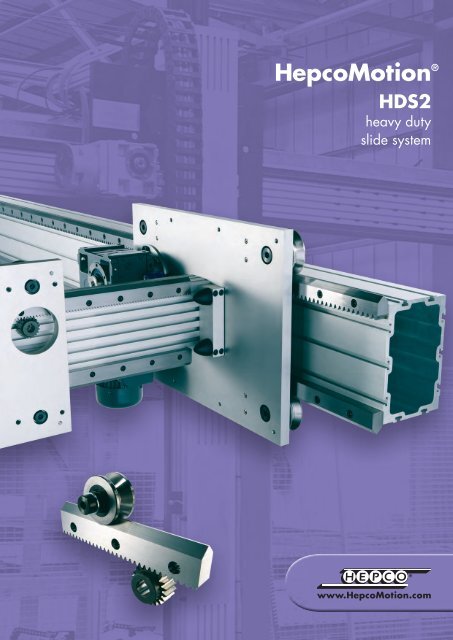
HepcoMotion ®<br />
HDS2<br />
heavy duty<br />
slide system
FOR AMENDMENTS & UPDATES VISIT www.HepcoMotion.com and select literature button<br />
Contents<br />
Introduction<br />
System Composition<br />
Application Examples<br />
Full Size Illustrations for Initial Selection<br />
1<br />
2-7<br />
8-9<br />
10-13<br />
Data and Dimensions for Individual Components<br />
V Slides & Flat Tracks<br />
Back Plates<br />
Bearings<br />
Construction Beams<br />
Buffer Units<br />
Assembled Beams<br />
Carriages<br />
Rack Driven Carriages<br />
Drive Flange Assembly<br />
AC Geared Motors<br />
Bearing Cap Wipers<br />
Roller Cap Wipers<br />
Lubricators<br />
Pinions<br />
Automatic Rack Lubrication<br />
Lubrication Accessories<br />
T-Nuts<br />
Bearing Blocks<br />
Technical Data<br />
Data and Dimensions for Assembled Systems<br />
Load Life Calculations<br />
Matched Systems<br />
Mix & Match Component Compatibility<br />
Installation<br />
Technical Specifications<br />
14-15<br />
16-17<br />
18-21<br />
22-23<br />
23<br />
24-25<br />
26-27<br />
28-29<br />
30<br />
31<br />
32<br />
33<br />
34<br />
35<br />
36<br />
37<br />
38<br />
39<br />
40-41<br />
42-44<br />
45<br />
46-47<br />
48<br />
49
Introduction<br />
HepcoMotion ® has updated the highly successful Heavy Duty Slide System, retaining the best features from the previous<br />
system, and incorporating them in a greatly expanded range under the name of HDS2. Many new components have been<br />
added including larger bearings, with increased load capacity, two sizes of construction beam, single edge V slides and<br />
flat track, as well as a range of drive options. All this, with an option for stainless steel or corrosion resistant components<br />
as standard, enables the HDS2 range to offer a solution for most customer's applications.<br />
Customers can choose from low cost commercial slides for general use or high precision ground slides to suit applications<br />
where accuracy and smoothness are key requirements.<br />
Customers can save design and manufacturing time by specifying ready mounted systems complete with rack driven<br />
carriages, safe in the knowledge that everything has been designed and tested by one of the world's leading specialists<br />
i li t h l<br />
2D & 3D CAD DISK<br />
www.HepcoMotion.com<br />
Features and Benefits<br />
Low cost commercial, precision ground and<br />
stainless steel systems available.<br />
Spur or helical rack & pinion options for ease of<br />
driving.<br />
Unique wiping action expels dirt and debris, in<br />
harsh environments<br />
Available as assembled units or in component form,<br />
providing maximum flexibility of design.<br />
Versatile construction beams for multiple design options<br />
<br />
<br />
<br />
<br />
<br />
<br />
<br />
System capacities up to 68 kN.<br />
Can operate without lubrication, ideal for food<br />
machinery and clean applications.<br />
Slides and tracks available in one piece up to 4 metres<br />
long, saves on assembly time.<br />
Long lengths comprising replaceable segments, reduces<br />
downtime in the event of damage.<br />
Flat tracks overcome necessity for parallel installation.<br />
Simple alignment facility to achieve parallelism of V<br />
slides<br />
Works in any plane and orientation for unrestricted use<br />
in machine construction.<br />
1
System Composition<br />
The HDS2 system comprises of a versatile family of slides, flat tracks, construction beams and other components, which will<br />
meet the requirements of the most demanding applications.<br />
2 to 7 provide an overview of the comprehensive HDS2 system. The slides and flat tracks may be attached to a suitable<br />
section, or they may be used in conjunction with Hepco back plates to give a ready made support profile. Slides and flat<br />
tracks can also be fitted to Hepco construction beams in many positions to provide a versatile all-in-one guide, drive and<br />
construction element.<br />
* Single Edge V Slide / Single Edge Flat Track 14 & 45 •<br />
*•<br />
*•<br />
*•<br />
*• Deep hardened running faces for maximum wear resistance.<br />
*• Unhardened centre allows customising.<br />
*• Spur & helical rack cut options provide means of driving.<br />
*•<br />
*•<br />
* Common V angle allows many bearing / slide combinations.<br />
*• Attractive corrosion inhibiting finish on all unground faces.<br />
Precision ground, low cost commercial, and stainless steel versions available.<br />
Available up to 4 metres long, unlimited lengths achieved by butting.<br />
Optional long lengths comprising replaceable short segments.<br />
Optional keyway for location & alignment via key or Hepco dowel pins.<br />
Narrow rail with register face for convenience of spacing apart.<br />
* Double Edge V Slide / Double Edge Flat Track 15 & 45 •<br />
• One piece construction with built in parallelism.<br />
Precision ground, low cost commercial, and stainless steel versions available.<br />
• Available up to 4 metres long, unlimited lengths achieved by butting.<br />
Optional long lengths comprising replaceable short segments.<br />
*<br />
*•<br />
*<br />
*•<br />
*• Deep hardened running faces for maximum wear resistance.<br />
*• Unhardened centre allows customising.<br />
*• Lightened centre with attractive debris cover.<br />
*•<br />
* Common V angle allows many bearing / slide combinations.<br />
*• Attractive corrosion inhibiting finish on all unground faces.<br />
Keyway for location & alignment via key or Hepco dowel pins.
System Composition<br />
Bearing & Roller common features 18-21<br />
*•<br />
*•<br />
*• Load capacity up to 50kN each.<br />
*•<br />
*•<br />
*• All options available in stainless steel.<br />
• Permits out of parallel installation.<br />
• Crowned contact face to overcome misalignment.<br />
* V Bearings / Track Rollers 18-21 •<br />
Special raceway conformity and low radial clearance, for slide applications.<br />
Double row bearings for tolerance of debris & high load capacity.<br />
Can be installed and removed without disengaging the carriage.<br />
Nitrile sealed for lifetime lubrication & to inhibit ingress of liquids & contaminants.<br />
Size 150<br />
Through hole fixing<br />
Bolt lengths to suit plate thickness from 7 to 40mm.<br />
Concentric (fixed) or eccentric (adjustable) studs.<br />
Can be installed & removed without carriage<br />
disengagement.<br />
Blind hole fixing<br />
For mounting into thick plates or where access to<br />
opposite side is restricted.<br />
Concentric (fixed) or eccentric (adjustable) studs.<br />
Can be installed & removed without removing slide.<br />
* V Bearing Cap Wiper / Roller Cap Wiper 32-33 •<br />
Lubricates contact faces reducing wear.<br />
In many cases re-lubrication is unnecessary.<br />
Excludes debris from bearing contact faces.<br />
* Removable cover allows adjustment of system without disassembly.<br />
*• Improves operational safety.<br />
Optional hardened stainless steel scraper.<br />
*•<br />
*•<br />
*•<br />
*•<br />
Lubricators 34<br />
Lubricates systems - increasing load & life.<br />
Lightly sprung felt wiper ensures low friction.<br />
Versions to fit slide, track, V bearing & track rollers.<br />
Blind and through hole fixing.<br />
3
System Composition<br />
* Low Narrow / Low Wide Back plates 16 •<br />
*• Strong construction in light weight aluminium.<br />
*• Profiles to suit single and double edge slides.<br />
* Adjustable alignment option to obtain parallelism<br />
of the system.<br />
*• Easily incorporated into customers design.<br />
*• Will attach to T-slot positions of construction beams.<br />
*• Key locations for attachment of slide and for mounting.<br />
*• Supplied clear anodised.<br />
*• Manufactured to precision extrusion tolerances.<br />
Back plate alignment dowel<br />
Adjustable alignment in conjunction with jacking screw,<br />
ensures parallelism between slides or tracks.<br />
Back plate location dowel<br />
Simple means of location and alignment, provides<br />
datum location.<br />
Back plate location dowel<br />
*• Spaces V slide and flat track away from mounting surface to allow the use of bearings, rollers and cap wipers.<br />
*• Male key for location on V slide and flat tracks.<br />
*• Female keyway for location using customer own key section, or Hepco dowel pins.<br />
High wide & high narrow back plates available 16-17 to suit slides with bearing blocks 39<br />
4
System Composition<br />
Bearing Block<br />
39<br />
Construction Beam 22-25<br />
High strength lightweight aluminium beams.<br />
3 useful sizes.<br />
Multiple slide & track mounting options.<br />
Stiff sections for long unsupported spans.<br />
Supplied fully assembled as required.<br />
Corner mounting positions to suit single edge slide & track.<br />
Common T-slot design for ease of connections.<br />
Plastic T-slot cover and metal end covers available.<br />
Location T-nut<br />
For alignment<br />
principle 17<br />
Flush T-nut<br />
Location T-nut<br />
T-Slot Fixing 16,17 & 25<br />
Multiple T-slot positions for attaching slides and tracks via back plates.<br />
Use of location and adjustment T-nuts for ease of assembly and alignment.<br />
Enables the use of double edge slide and flat track to be fitted to construction beams.<br />
Adjustment T-nut<br />
Quick fit T-nuts<br />
T-Nuts 38<br />
Simple means of attaching components.<br />
Plastic or spring retainer prevents loss of position.<br />
Location type fits into the back plate keyway.<br />
Adjustment type for ease of alignment.<br />
Multiple thread sizes are available.<br />
Flush T-nut Location T-nut Adjustment T-nut<br />
5
System Composition<br />
The HDS2 range has been greatly extended to include assembled carriages, 3 sizes of construction beam, larger capacity<br />
bearings and a host of improved features. This also provides flexibility for many sizes and types of heavy duty components<br />
to be interchanged in order to achieve a comprehensive combination of space and performance possibilities.<br />
Assembled Beams with Carriages 26-27<br />
Fully assembled factory built beam with ready adjusted carriage.<br />
Available for all opposing corner mounted V slide options for all sizes of beam.<br />
Optional integrated buffer units with / without access for drive belt.<br />
Compatible with all rack driven carriage units 28-29.<br />
Available up to 6 metres in one length.<br />
Unlimited lengths available by butting - beam<br />
joining plates supplied.<br />
Carriages 26-27<br />
Factory adjusted to double edge slide, or beam assembly as required.<br />
Available with bearings only, or with addition of cap wipers or lubricators.<br />
Hardened stainless steel scrapers available for cap wipers.<br />
Tapped holes in convenient positions for attachment purposes.<br />
Compatible with both precision ground and commercial slides.<br />
Corrosion resistant options available on all sizes.<br />
<br />
<br />
Strong construction beam, ideal as<br />
self supporting member.<br />
Hollow centre for belt, cable or<br />
chain return.<br />
Rack Driven Carriage Unit 28-29<br />
Sizes to suit all beams.<br />
Optional automatic rack lubrication.<br />
6
System Composition<br />
HDCS - Heavy Duty Compact Screw Driven Unit<br />
High performance linear transmission.<br />
High capacity, high precision.<br />
Compact high strength aluminium beam.<br />
Play free ballscrew, allows accurate positioning.<br />
Ballscrew lubrication point.<br />
Optional bellows cover.<br />
Easy fitting for limit switches.<br />
Integrated buffers.<br />
Not detailed in this catalogue.<br />
For details of the HDCS product visit<br />
www.HepcoMotion.com/hdcsdatauk<br />
and select datasheet No. 1 HDCS<br />
Ring Systems<br />
Track Systems<br />
Heavy Duty Ring Slides and Track Systems - HDRT<br />
Ring and segment sizes from Ø512 to Ø1656mm.<br />
Ring slides with internal, external and opposing vees.<br />
Ring segments and gear cut options available.<br />
Track Systems with fixed centre or bogie carriages<br />
Not detailed in this catalogue. For details of the HDRT product visit www.HepcoMotion.com<br />
or request separate catalogue<br />
Heavy Duty Driven Linear System - HDLS<br />
High performance linear transmission.<br />
Steel reinforced timing belt drive.<br />
AC geared motor option.<br />
Speeds up to 6m/s.<br />
3 formats available, narrow, wide<br />
& angled.<br />
Lengths up to 6m in one piece.<br />
Unlimited lengths available with butting.<br />
Not detailed in this catalogue. For details of the HDLS product visit www.HepcoMotion.com<br />
or request separate catalogue<br />
7
Application Examples<br />
Gantry Robot<br />
The HDS2 system contains all the major components to produce high capacity gantry systems such as that shown below.<br />
The extreme rigidity of the construction beams 1 allow for long unsupported spans up to 6m depending on load. The use<br />
of V slides 2 on one side of the X axis and flat tracks 3 on the other makes allowances for the variation in parallelism<br />
between the two beams. The common drive shaft 4 allows for the Y axis to be driven from both X axis beams, via the<br />
integrated racks on both the V slide and flat tracks. The ends of the Y axis beam have been tapped to allow direct<br />
connection into the driven carriages 5 on the X axis. Both X & Y axis beams have been fitted with buffer units for end of<br />
stroke protection. The Z axis incorporates a Hepco HDCS unit 6 , which is driven via a ballscrew, this provides both the<br />
precision and capacity required for this type of application.<br />
1 2<br />
5<br />
6<br />
3<br />
4<br />
Z<br />
Y<br />
X<br />
Driven Carriage Assembly<br />
2<br />
This example shows the ease with which a single edge V slide 1<br />
and narrow flat track 2 can be spaced apart using a requisite<br />
number of cross members 3 of equal length. In this way the<br />
slide and track form integral members of the frame<br />
therefore saving both weight and cost.<br />
1<br />
3<br />
By using a V slide on<br />
one side and flat track<br />
on the other, the necessity for<br />
precise parallelism of the two<br />
elements is overcome.<br />
The rack cut version of the slide provides<br />
an easy means of driving and the carriage<br />
assembly is prevented from lifting off by the drive<br />
pinion one side and the single track roller 4 the other.<br />
HepcoMotion systems division specialises in the design and manufacture of special machines<br />
incorporating its products. Some typical examples are shown above.<br />
8
Application Examples<br />
Pick and Place Application<br />
This example shows a 4 axis pick and place system using a combination of Hepco HDS2, HDLS and HDRT parts. HDLS &<br />
HDRT are related products featured on page 7 and detailed in separate Hepco catalogues. The X axis comprises of the<br />
HDLS unit which 1 is driven via a steel reinforced timing belt and incorporates an HB25 beam. It is ideally suited to high<br />
speed applications of this nature.<br />
Z<br />
Y<br />
3<br />
X<br />
4<br />
1<br />
The vertical axis<br />
is rotated via a single<br />
edge HDRT ring 2 which has<br />
high moment load capacity to support the<br />
2<br />
Y & Z axes.<br />
The Y axis uses a HB25C beam 3 which is compact and<br />
light weight enabling this axis to be used as a cantilever arm.<br />
The Z axis uses a HB25 beam which is connected to the ring carriage 4 via<br />
the tapped hole option at the end of the beam providing an easy and quick<br />
mounting solution.<br />
1<br />
Cable Tensioning Application<br />
This example shows 8 x THJR95 V bearings mounted on a special<br />
carriage plate supporting the cable clamp. The widely spaced<br />
pairs of bearings give very high moment load capacity the<br />
inner set providing additional capacity at the<br />
point of greatest load. The outermost bearings<br />
on one side are the concentric type, the rest<br />
are the eccentric type. This allows the system<br />
to be adjusted such that all bearings share<br />
the load equally. The bearings run on<br />
single edge V slides 2 spaced<br />
wide apart on a custom<br />
built back plate which<br />
provides high moment<br />
load capacity in the<br />
other direction.<br />
2 1<br />
Hepco can<br />
manufacture parts to<br />
customer drawings such as the<br />
back plate & carriage shown in this<br />
application. This allows customers to receive<br />
fully built assemblies, with factory set bearings.<br />
HepcoMotion systems division specialises in the design and manufacture of special machines<br />
incorporating its products. Some typical examples are shown above.<br />
9
Full Size Illustrations For Initial Selection<br />
Full size illustrations of the basic V slide systems and flat track systems together with load capacity are shown on this and<br />
the following 3 pages as a guide to facilitate initial selection. Once a choice has been made, customers should refer to<br />
individual component pages for dimensions and to 42-44 for comprehensive details on load and life. Combinations other<br />
than shown in this section are possible, please refer to the Mix & Match tables on 46-47. There is a wide range of other<br />
components complementary to the V slide systems and flat track systems. These are illustrated on the system composition<br />
2-7 cross referenced to the relevant component pages.<br />
Please note that bearing cap wipers and roller cap wipers are not shown on the illustrations. These will increase the space<br />
required very slightly 32.<br />
Slide Bearing System Load (Lubricated)<br />
Size &<br />
Type<br />
Part No. Ø Part No. L1 L2 Ms<br />
25<br />
Single Edge<br />
C/P/SS HSS25 64 B/THJR64 10 000N 16 000N Variable<br />
25<br />
Single Edge<br />
C/P/SS HSS25 95 B/THJR95 28 000N 40 000N Variable<br />
25<br />
Single Edge<br />
C/P/SS HSS25 120 B/THJR120 40 000N 60 000N Variable<br />
25<br />
Double Edge<br />
C/P/SS HSD25 64 B/THJR64 10 000N 16 000N 450Nm<br />
25<br />
Double Edge<br />
C/P/SS HSD25 95 B/THJR95 28 000N 40 000N 1280Nm<br />
25<br />
Double Edge<br />
C/P/SS HSD25 120 B/THJR120 40 000N 60 000N 1820Nm<br />
33<br />
Single Edge<br />
C/P/SS HSS33 128 B/THJR128 40 000N 60 000N Variable<br />
33<br />
Single Edge<br />
C/P/SS HSS33 150 B/THJR150 68 000N 100 000N Variable<br />
Load capacities apply to steel systems, for stainless steel systems load capacities are 25% lower<br />
L1<br />
L1<br />
Ms<br />
L2<br />
Ø64<br />
25<br />
25 Size<br />
Single Edge<br />
Slide<br />
Ø64<br />
V Bearing<br />
25 Size Doub<br />
10
Full Size Illustrations For Initial Selection<br />
Ø128<br />
Bearings<br />
18-21<br />
33<br />
33 Size<br />
Single Edge<br />
Slide<br />
Ø128<br />
V Bearing<br />
Slides<br />
14-15<br />
Backplates<br />
16-17<br />
Mix & Match<br />
46<br />
25<br />
25 Size<br />
Single Edge<br />
Slide<br />
Ø120<br />
V Bearing<br />
Ø95<br />
le Edge Slide<br />
Ø95<br />
V Bearing<br />
25 Size<br />
Single Edge<br />
Slide<br />
11
Full Size Illustrations For Initial Selection<br />
Ø150<br />
33<br />
33 Size<br />
Single Edge<br />
Slide<br />
Ø150<br />
V Bearing<br />
Ø144<br />
33<br />
33 Size<br />
Single Edge<br />
Flat Track<br />
Ø144<br />
Track Roller<br />
12
Full Size Illustrations For Initial Selection<br />
LR<br />
Track Roller<br />
Load<br />
Capacity<br />
Ø Part No. LR<br />
58 B/THRN58 5 000N<br />
58 B/THRR58 10 000N<br />
89 B/THRR89 20 000N<br />
122 B/THRR122 30 000N<br />
144 B/THRR144 80 000N<br />
Bearings<br />
18-21<br />
Slides<br />
14-15<br />
Ø89<br />
Ø89<br />
Track Roller<br />
Backplates<br />
16-17<br />
Ø58<br />
Ø58<br />
Track Roller<br />
B/THRR58..<br />
Mix & Match<br />
46<br />
25<br />
25 Size<br />
Double Edge<br />
Flat Track<br />
Ø122<br />
Ø122<br />
Track Roller<br />
25 Size<br />
Single Edge<br />
Flat Track<br />
25<br />
Ø58<br />
Ø58 Narrow<br />
Track Roller<br />
B/THRN58..<br />
33<br />
33 Size<br />
Single Edge<br />
Flat Track<br />
13
V Slides & Flat Tracks<br />
Hepco HDS2 V slides and flat tracks are manufactured from high quality bearing steel, hardened on the wearing surfaces.<br />
Other areas are left soft for customising. All sizes are available in precision ground, commercial and stainless steel grades.<br />
The precision and stainless steel grades are ground on the wearing surfaces and mounting face to provide accuracy and<br />
smooth operation. The commercial grade is etched on the wearing surfaces to aid lubrication retention and is suitable for<br />
many applications. Single edge slides and tracks are available with a spur or helical rack cut into the rear face. These are<br />
also available with a keyway for use with Hepco back plates or dowel pins.<br />
Popular options available on request: Non standard lengths and holes - Butt jointed profiles of unlimited length *2<br />
45 - Matched and replaceable short butted sets 45 - Hardened racks *5<br />
L<br />
+0.25<br />
- 2.25<br />
(see notes 1 & 2)<br />
90°<br />
C<br />
E ± 0.25<br />
E ± 0.25<br />
D<br />
C<br />
ØG<br />
Single Edge V Slide (...HSS...)<br />
L +0.25<br />
- 2.25 (see notes 1 & 2)<br />
E ± 0.25 E ± 0.25<br />
ØH<br />
D<br />
F<br />
K<br />
J<br />
M<br />
B<br />
Plain<br />
version<br />
A<br />
P<br />
Keyway<br />
version<br />
N<br />
Dowel pin<br />
SDP12/16<br />
17<br />
ØG<br />
Narrow Flat Track (...HTS...)<br />
ØH<br />
F<br />
K<br />
J<br />
M<br />
B<br />
A<br />
P<br />
N<br />
Dowel pin<br />
SDP12/16<br />
17<br />
Part<br />
J<br />
A B C D E F G H Rack Module K L M N P<br />
Number<br />
2.5 3 4 5<br />
kg/m ~<br />
CHSS 25 51.7 25.4 43 43 90 17.7 15 10 15.1 14.6 - - 32.7 4046 8.5 12 4.2 8<br />
SS/PHSS 25 51.2 25 43 43 90 17.5 15 10 15.1 14.6 - - 32.5 4046 8.5 12 4 8<br />
CHSS 33 57.7 33.4 58 58 120 26.2 20 14 - - 22.1 21.1 30.2 3956 12.7 16 4.2 12.3<br />
SS/PHSS 33 57.2 33 58 58 120 26 20 14 - - 22.1 21.1 30 3956 12.5 16 4 12.3<br />
CHTS 25 43.1 25.4 43 43 90 17.7 15 10 15.1 14.6 - - 25.4 4046 8.5 12 4.2 7.7<br />
SS/PHTS 25 42.7 25 43 43 90 17.5 15 10 15.1 14.6 - - 25.2 4046 8.5 12 4 7.7<br />
CHTS 33 44.7 33.4 58 58 120 26.2 20 14 - - 22.1 21.1 18.5 3956 12.7 16 4.2 11.7<br />
SS/PHTS 33 44.2 33 58 58 120 26 20 14 - - 22.1 21.1 18.3 3956 12.5 16 4 11.7<br />
Rack Type & Module Availability<br />
Module<br />
Rack<br />
Type *4 HSS25 HTS25 HSS33 HTS33<br />
2.5 Spur <br />
2.5 Helical <br />
3 Spur <br />
4 Helical <br />
5 Spur <br />
= Standard option<br />
= Not available<br />
Helical racks are not available for SS versions<br />
Type<br />
*6<br />
..HSS...<br />
..HTS...<br />
Precision /<br />
Stainless steel<br />
Commercial Type<br />
Grade<br />
*6<br />
..HSD...<br />
..HTD...<br />
Indicates surfaces which are precision ground<br />
Precision /<br />
Commercial Grade<br />
Stainless steel<br />
Notes:<br />
1. Any length of slide up to 4046mm long can be supplied in one piece, but for optimum price and delivery, slide<br />
lengths should be specified with C & D dimensions as shown in the above table.<br />
2. Butt jointed slides of unlimited length are available. The hole pitch will be maintained across the joint. See installation details 45<br />
3. Tooth pitch positions relative to the hole pitch may vary between components. Customers using rack cut profiles in parallel should<br />
ensure that one drive pinion can be adjusted relative to the other in order to compensate. Rack cut profiles to a regulated or matched<br />
tooth position are available on request.<br />
4. Helical racks have a left handed helix angle of 30 degrees.<br />
5. Hardened racks are available on request, ..HSS/HTS25 with mod 3 racks are supplied with hardened rack as standard.<br />
6.<br />
+0.3<br />
Commercial V slides and flat tracks are manufactured to -0.0<br />
+0.1<br />
tolerance on width and -0.0 tolerance on thickness, precision and<br />
stainless steel versions are manufactured to ±0.025 on both width and thickness. Finish is generally to N5.<br />
14
V Slides & Flat Tracks<br />
Hepco double edge slides and wide flat tracks have built in parallelism for ease of setting. Both are supplied with flush<br />
fitting plastic covers and end caps to prevent entrapment of debris. Double edge slides and wide flat tracks are supplied<br />
with a keyway for locating to a key register, Hepco dowel pins or back plates. Stainless steel versions are available and<br />
have a slightly different design, without the central recess or plastic cover and with mounting holes and counterbores to<br />
suit M8 cap head screws to DIN912.<br />
Optional<br />
Keyway<br />
Stainless Steel<br />
SS HSD25<br />
Double Edge V Slide (...HSD...)<br />
L<br />
+0.25<br />
-2.25<br />
(see note1)<br />
C E ±0.25 E ±0.25<br />
D<br />
M8 DIN 7984 * 9<br />
Standard<br />
P/C HSD25<br />
90º<br />
Bearings<br />
18-21<br />
Backplates<br />
16-17<br />
B<br />
A<br />
Dowel pin<br />
SDP15<br />
17<br />
Assembled<br />
Systems<br />
40-41<br />
9<br />
Ø10<br />
Ø15<br />
L<br />
+0.25<br />
-2.25<br />
(see note1)<br />
ØN<br />
F<br />
Assembled<br />
Beams<br />
24-25<br />
M<br />
C<br />
E ±0.25 E ±0.25<br />
D<br />
M<br />
Assembled<br />
Carriages<br />
26-27<br />
K<br />
J<br />
H<br />
K<br />
B<br />
Stainless Steel<br />
SS HTD25<br />
Wide Flat Track (...HTD...)<br />
G<br />
Standard<br />
P/C HTD25<br />
Dowel pin<br />
SDP15<br />
17<br />
Rack Driven<br />
Carriages<br />
28-29<br />
Part<br />
A B C D E F G H J K L M N<br />
Number<br />
kg/m ~<br />
CHSD 25 103 100.4 43 43 90 25.4 8.2 30 52.6 15 4046 5.35 10 13.5<br />
SS/PHSD 25 102.4 100 43 43 90 25 8 30 52.6 15 4046 5.15 10 13.5<br />
CHTD 25 - 85.8 43 43 90 25.4 8.2 30 52.6 15 4046 5.35 10 12.5<br />
SS/PHTD 25 - 85.4 43 43 90 25 8 30 52.6 15 4046 5.15 10 12.5<br />
Ordering Example<br />
P HSS25 L2040 NK R C30 D30<br />
Lubrication<br />
32-34<br />
Automatic<br />
Lubrication<br />
36<br />
Precision grade<br />
Bespoke values of C & D<br />
P = Precision, C = Commercial, SS = Stainless Steel Leave blank if standard* 1<br />
Part number Rack option* 8<br />
R = Spur rack, HR = Helical rack<br />
Leave blank if not required<br />
Slide or Track length Non keyway version* 7 & 10<br />
Leave blank if keyway required<br />
Notes:<br />
7. Single edge slides & flat tracks for corner mounting to Hepco beams should be ordered without keyway ‘NK’ 24. The keyway<br />
version is useful for customers own location requirements and is necessary when using Hepco back plates 16 & 25.<br />
8. HSS & HTS 25 slide and flat tracks have an option of 2.5 or 3 module spur rack. 2.5 module rack is supplied as standard when ‘R’<br />
is added to the part number. If 3 module rack is required add 3 after ‘R’ to confirm size required. Helical racks are not available<br />
for stainless steel slides or flat tracks.<br />
9. M8 low head cap screws are available from Hepco in the following lengths: 30mm (part no. FS8-30) for use without back plate,<br />
40mm (part no. FS8-40) for use with low back plates & 60mm (part no. FS8-60) for use with high back plates. HSS and HTS slides<br />
and tracks can use widely available standard M8 & M12 capscrews DIN 912.<br />
10. Standard double edge V slides and flat tracks are not available in 'NK' version.<br />
ABC<br />
XYZ +<br />
123<br />
Pinions<br />
35<br />
Technical<br />
42-45<br />
Mix & Match<br />
46<br />
15
Back Plates<br />
HDS2 back plates are designed to space the V slides and flat tracks off the mounting surface, providing clearance to<br />
accommodate the V bearings and track rollers plus their respective lubrication devices 47. They may be used either<br />
within the customer’s own machine design or in conjunction with the construction beams 25. The male key section is<br />
designed to locate in the optional keyway of the slide and flat tracks whilst the female keyway section(s) are designed<br />
to locate either with the customer’s own key section or with Hepco dowel pins. The HHN25 and HLN narrow type back<br />
plates may be ordered with a jacking screw alignment facility to enable one slide or track to be set exactly parallel to<br />
another within a system (see opposite).<br />
L *1<br />
A<br />
A<br />
C E ØH D<br />
N<br />
S<br />
N<br />
S<br />
F<br />
8<br />
B<br />
8<br />
B<br />
Low Narrow Back Plate<br />
P<br />
P<br />
R<br />
R<br />
26<br />
HLN25 HLN33<br />
L *1<br />
A<br />
C<br />
E<br />
ØH<br />
D<br />
N<br />
10<br />
S 125º<br />
135º<br />
F B<br />
7<br />
8 12<br />
High Narrow Back Plate<br />
P<br />
R<br />
60<br />
HHN25 & 33<br />
E<br />
C<br />
E<br />
C<br />
E<br />
M<br />
G<br />
C<br />
G<br />
J<br />
K<br />
Hole Configuration 'A' *2&5<br />
Part<br />
Number<br />
For Use With<br />
A B C D E F G *4 H J *4 K *4 L M *4 N P R S<br />
kg/m<br />
HLN 25 HSS 25 HTS 25 33 13 *1 *1 90 16.6 5 10 35 45 6026 90 12<br />
HLN 33 HSS 33 HTS 33 39 15 *1 *1 120 18.6 5 14 50 60 5996 120 16<br />
HLW 25 HSD 25 HTD 25 66 13 *1 *1 90 17.7 - 10 - - 6026 - 15<br />
HHN 25 HSS 25 HTS 25 27 34.5 *1 *1 90 38.1 5 10 35 45 6026 90 12<br />
HHN 33 HSS 33 HTS 33 27 30.8 *1 *1 120 34.4 5 14 50 60 5996 120 16<br />
HHW 25 HSD 25 HTD 25 54 34.5 *1 *1 90 39.2 - 10 - - 6026 - 15<br />
+0<br />
12 +0.2 16.5 3.6 1.0<br />
-0.2 -0<br />
+0<br />
14 +0.3 19.5 3.6 1.6<br />
-0.3 -0<br />
+0<br />
12 +0.2 33 4.7 2.25<br />
-0.2 -0<br />
+0<br />
12 +0.2 20 3.6 3.8<br />
-0.3 -0<br />
+0<br />
14 +0.3 21 3.6 3.7<br />
-0.2 -0<br />
+0<br />
12 +0.2 35 4.7 5.3<br />
-0.2 -0<br />
Notes<br />
1. Overall lengths (‘L’ dimension) should be ordered to correspond with the length of slide or track ensuring that ‘C’ & ‘D’ dimensions<br />
also correspond. Back plate lengths up to 6026mm are available in one piece to suit butted matched sets 45.<br />
2. HLN back plates will be supplied with tapped holes and M8 dog point socket set screws to ISO 4028<br />
for customers requiring the jacking screw alignment facility. Hole configuration ‘B’ denotes jacking screw positions<br />
corresponding with fixing hole positions, necessary when used in conjunction with the construction beams (see figure 1). Hole<br />
configuration ‘A’ denotes jacking screw positions mid way between fixing hole positions and is for general use where customers<br />
provide their own centre key section or use Hepco alignment dowel pins SDPA as shown in figure 2.<br />
3. Holes for Hepco dowel pins should be reamed to a tolerance K6. Dowel pin head Ø tolerance for engagement with keyway is m6.<br />
4. Dimensions G,J,K & M only apply for back plates supplied with either type 'A' or type 'B' hole configurations.<br />
5. Type 'B' hole configuration is only available for the HLN25 & HHN25 back plates. Type 'A' hole configurations are available for all<br />
narrow type back plates.<br />
16
Back Plates<br />
Mounting surfaces and location faces are manufactured to precision extrusion tolerances and are adequate for most<br />
applications. Back plates are manufactured from high strength aluminium and are supplied clear anodised. Compatibility<br />
of back plates with the various sizes and types of slide, tracks, bearings and lubricators can be found on 46 & 47.<br />
B<br />
ØA<br />
Low Wide Back Plate<br />
8 3.5<br />
135º<br />
P<br />
E<br />
SDPA<br />
8<br />
+0.2<br />
-0.0<br />
A<br />
N<br />
30±0.15<br />
R<br />
HLW25<br />
R<br />
A<br />
30±0.15<br />
N<br />
10 3.5<br />
Dowel Pins<br />
70<br />
HHW25<br />
8 +0.2<br />
-0.0<br />
High Wide Back Plate<br />
P<br />
S<br />
B<br />
S<br />
+0.018<br />
Ø A (m6 +0.007)<br />
8<br />
Alignment procedure<br />
It is normal to use one adjustable slide/<br />
track and back plate element in conjunction<br />
with one non-adjustable element. The nonadjustable<br />
element should be located onto<br />
a key, Hepco dowel pins, or otherwise set<br />
adequately straight for the application and<br />
bolted down tight.<br />
Where the Hepco construction beams are used,<br />
the non-adjustable element should be located by<br />
means of Hepco location T-nuts types ‘L’ and the<br />
adjustable element by means of the alignment<br />
T-nuts type ‘A’. (for T-nut details 38).<br />
For applications not requiring a construction<br />
beam, the adjustable element should be located<br />
onto a reduced width key section or Hepco<br />
dowel pins type SDPA midway between hole<br />
centres. The hole in the mounting surface for<br />
fixing, should be spotted and drilled from the<br />
back plate to ensure even clearance around the<br />
screws.<br />
The adjustable element should be set parallel<br />
to the non-adjustable element at the end hole<br />
positions with the jacking screws set for even<br />
clearance around the fixing screws and the end<br />
screws tightened down. Working outwards from<br />
the centre of the element and with all but the<br />
end screws fully retracted, each jacking screw<br />
should be progressively jacked in to influence<br />
the elements parallel with the corresponding<br />
position on the opposing element then both<br />
jacking screws locked and the corresponding<br />
fixing screw tightened down. Depending upon<br />
available hole clearances, it is possible to bend<br />
an element up to 1mm pro-rata per metre.<br />
D<br />
B<br />
SDP<br />
+0.018<br />
ØC (m6 +0.007 )<br />
Stainless steel dowel pins are available, prefix the part number<br />
with SS. Example - SS SDP 8<br />
Alignment principle for<br />
use with Hepco beam.<br />
Hole configuration ‘B’ *2<br />
Fig 1.<br />
General alignment principle<br />
Hole configuration ‘A’ *2<br />
Fig 2.<br />
Part<br />
Number<br />
ØA *3 B ØC *3 D E<br />
SDP8 8 8 6 2.75 -<br />
SDP12 12 15 10 3.75 -<br />
SDP14 14 15 12 3.75 -<br />
SDP15 15 15 10 4.75 -<br />
SDP16 16 15 12 3.75 -<br />
SDPA14 14 20 10 7.5 10<br />
SDPA16 16 20 12 7.5 12<br />
Slides<br />
14-15<br />
Bearings<br />
18-21<br />
Assembled<br />
Systems<br />
40-41<br />
T-Nuts<br />
38<br />
Mix & Match<br />
46<br />
Ordering Example for Back Plates<br />
HLN 25 L1886 C43 D43 A<br />
Part Number Alignment type A or B *5<br />
Leave blank if not required<br />
V slide or flat track size<br />
Overall length C & D dimensions *1<br />
17
V Bearings<br />
Hepco HJR bearings use double row ball bearings on sizes 64 to 128 and twin taper roller bearings on size 150. These<br />
provide high axial and radial load capacity. The design allows for easy assembly, and bearings can be removed from a<br />
system with a single screw. Each bearing has a chemically blacked, high tensile steel journal and bush and is available in<br />
concentric and eccentric (adjustable) forms. Each bearing is available with either a blind or through-hole fixing. Stainless<br />
steel versions are available as standard.<br />
Blind Hole<br />
Fixing Type - BH<br />
D<br />
L<br />
*2<br />
Double row ball<br />
bearing for sizes<br />
Ø64 - Ø128<br />
F<br />
Eccentric<br />
type only<br />
H<br />
ØB<br />
ØE F6<br />
Hole fit<br />
for min. distance ‘L’<br />
W<br />
Twin taper<br />
roller bearings<br />
for size Ø150<br />
C<br />
G<br />
J<br />
K<br />
Part Number<br />
ØA<br />
For Use With V Slide<br />
ØB<br />
±0.015<br />
C<br />
D<br />
ØE<br />
F6<br />
F G H J K L<br />
BHJR.. 64 HSS 25 HSD 25 41 34 22 16 1.25 27 M10 43 26 10<br />
THJR.. 64 HSS 25 HSD 25 41 34 22 16 1.25 27 M12 - - -<br />
BHJR.. 95 HSS 25 HSD 25 72 34 22 20 2 40 M16 44 41 11.5<br />
THJR.. 95 HSS 25 HSD 25 72 34 22 20 2 40 M16 - - -<br />
BHJR.. 120 HSS 25 HSD 25 96 40 28 25 3 50 M24 54 56 17<br />
THJR.. 120 HSS 25 HSD 25 96 40 28 25 3 50 M24 - - -<br />
BHJR.. 128 HSS 33 - 96 40 28 25 3 50 M24 54 56 17<br />
THJR.. 128 HSS 33 - 96 40 28 25 3 50 M24 - - -<br />
BHJR.. 150 HSS 33 - 118 60 40 38 2 65 M36 80 70 21<br />
THJR.. 150 HSS 33 - 118 60 40 38 2 65 M36 - - -<br />
Mounting Plate Screw Lengths<br />
Part Number<br />
min<br />
T *1<br />
max<br />
THJR 64 ... 12 6.5 12.5<br />
THJR 64 ... 17 11.5 17.5<br />
THJR 64 ... 22 16.5 22.5<br />
THJR 64 ... 27 21.5 27.5<br />
THJR 95 ... 16 9 16<br />
THJR 95 ... 22 16 22<br />
THJR 95 ... 27 21 27<br />
THJR 95 ... 32 26 32<br />
Part Number<br />
min<br />
T *1<br />
max<br />
THJR 120 ... 17 6.5 17<br />
THJR 120 ... 27 16.5 27<br />
THJR 120 ... 37 26.5 37<br />
THJR 128 ... 17 6.5 17<br />
THJR 128 ... 27 16.5 27<br />
THJR 128 ... 37 26.5 37<br />
THJR 150 ... 25 6.5 25<br />
THJR 150 ... 40 21.5 40<br />
Notes:<br />
1. When using THJR bearings, the part number must be selected to suit the required plate thickness, T. Choose from the tables above.<br />
2. Adjustment tools for V bearing and track rollers are available. Please order part number AT54 for HJR64, AT95 for HJR95. AT128<br />
for HJR120/HJR128, and AT150 for HJR150.<br />
18
V Bearings<br />
All bearings are greased for life and incorporate nitrile seals to inhibit ingress of liquids and contaminants. Customers are<br />
strongly recommended to provide lubrication to the interface between the bearings and the slide by specifying Hepco cap<br />
wipers or lubricators which contact the vee of the slide or the bearing. This lubrication greatly increases the load capacity<br />
and life.<br />
Through Hole<br />
Fixing Type - TH<br />
Slides<br />
14-15<br />
M<br />
T<br />
Double row ball<br />
bearing for sizes<br />
Ø64 - Ø128<br />
R<br />
W<br />
H<br />
F<br />
Eccentric<br />
type only<br />
Backplates<br />
16-17<br />
ØA<br />
ØS<br />
ØU<br />
Assembled<br />
Systems<br />
40-41<br />
ØE F6<br />
Hole fit<br />
Twin taper<br />
roller bearings<br />
for size Ø150<br />
90°<br />
N<br />
G<br />
Assembled<br />
Carriages<br />
26-27<br />
M<br />
P<br />
Max Working Load<br />
Capacity *3<br />
M N P R ØS ØU W kg~<br />
Bearing Static (Co) & Dynamic (C)<br />
Radial Load Capacities *4<br />
Axial (N) Radial (N) Co (N) C (N)<br />
- 5 - - - - 10 0.65 2500 8000 12 899 21 373<br />
40 5 2.5 13.5 24 28 8 0.65 2500 8000 12 899 21 373<br />
- 5 - - - - 12 1.45 7000 20 000 29 340 41 823<br />
40 5 3 17 30 34 10 1.45 7000 20 000 29 340 41 823<br />
- 8 - - - - 14 3.0 10 000 30 000 43 200 63 830<br />
50 8 4 22 40 44 14 3.0 10 000 30 000 43 200 63 830<br />
- 8 - - - - 14 3.0 10 000 30 000 43 200 63 830<br />
50 8 4 22 40 44 14 3.0 10 000 30 000 43 200 63 830<br />
- 10 - - - - 19 7.5 17 000 50 000 218 000 150 018<br />
80 10 5 33 60 66 22 7.5 17 000 50 000 218 000 150 018<br />
Rack Driven<br />
Carriages<br />
28-29<br />
Lubrication<br />
32-34<br />
ABC<br />
XYZ +<br />
123<br />
Technical<br />
42-45<br />
Ordering Example<br />
SS THJR 95 C NS 16<br />
Mix & Match<br />
46<br />
SS = stainless steel option, Plate thickness *1<br />
Leave blank if not required, *3&5<br />
& tables left. Leave blank for BHJR<br />
Part number: THJR = through hole<br />
BHJR = blind hole<br />
Bearing diameter<br />
NS = nitrile seals<br />
Journal type: E = eccentric<br />
C = concentric<br />
Notes:<br />
3. Load capacities stated, assume lubrication at the bearing/slide interface. Stainless steel versions have a 25% lower capacity.<br />
4. The quoted static and dynamic load capacities are based on industry standard calculations. These do not accurately reflect<br />
performance, and are only provided for comparison with other systems. Please use Max Working Load figures and the load/life<br />
calculations on 42-44 to determine system performance.<br />
5. SS versions of the size 150 bearing contains a steel twin taper roller bearing, protected by nitrile seals.<br />
19
Track Rollers<br />
Hepco HRR track rollers use double row ball bearings on sizes 58 to 122 and twin roller bearing on size 144, these<br />
provide high radial load capacity. The design allows for easy assembly, and track rollers can be removed from a system<br />
with a single screw. Each track roller has a chemically blacked, high tensile steel journal and bush and is available in<br />
concentric and eccentric (adjustable) forms. Each track roller is available with either a blind or though-hole fixing. Stainless<br />
steel versions are available as standard.<br />
Blind Hole<br />
Fixing Type - BH<br />
Double row ball<br />
bearing for sizes<br />
Ø58 - Ø122<br />
D<br />
L<br />
*2<br />
F<br />
Eccentric<br />
type only<br />
H<br />
ØA<br />
ØE F6<br />
Hole fit<br />
for min. distance ‘L’<br />
W<br />
Twin taper<br />
roller bearings<br />
for size Ø144<br />
C<br />
G<br />
J<br />
K<br />
Part Number<br />
ØA<br />
For Use With Flat Track<br />
C<br />
D<br />
ØE<br />
F6<br />
F G H J K<br />
BHRR.. 58 HTS 25 HTD 25 34 22 16 1.25 27 M10 43 26<br />
THRR.. 58 HTS 25 HTD 25 34 22 16 1.25 27 M12 - -<br />
BHRR.. 89 HTS 25 HTD 25 34 22 20 2 40 M16 44 41<br />
THRR.. 89 HTS 25 HTD 25 34 22 20 2 40 M16 - -<br />
BHRR.. 122 HTS 33 - 40 28 25 3 50 M24 54 56<br />
THRR.. 122 HTS 33 - 40 28 25 3 50 M24 - -<br />
BHRR.. 144 HTS 33 - 60 40 38 2 65 M36 80 70<br />
THRR.. 144 HTS 33 - 60 40 38 2 65 M36 - -<br />
Mounting Plate Screw Lengths<br />
Part Number<br />
min<br />
T *1<br />
max<br />
THRR 58 ... 12 6.5 12.5<br />
THRR 58 ... 17 11.5 17.5<br />
THRR 58 ... 22 16.5 22.5<br />
THRR 58 ... 27 21.5 27.5<br />
THRR 89 ... 16 9 16<br />
THRR 89 ... 22 16 22<br />
THRR 89 ... 27 21 27<br />
THRR 89 ... 32 26 32<br />
Part Number<br />
Notes:<br />
1. When using THRR Track rollers, the part number must be selected to suit the required plate thickness, T. Choose from the tables above.<br />
2. Adjustment tools for V bearing and track rollers are available. Please order part number AT54 for HRR58, AT95 for HRR89, AT128<br />
for HRR122, and AT150 for HRR144.<br />
3. Load capacities stated are for steel bearings, stainless steel versions have a 25% lower capacity.<br />
4. With THRN58 a washer is supplied. Fixing screw lengths depend on application and are not included. Use M10 screws in material<br />
condition 8.8 or stronger.<br />
5. The quoted static and dynamic load capacities are based on industry standard calculations. These do not accurately reflect<br />
performance, and are only provided for comparison with other systems. Please use max working load figures and the load/life<br />
calculations on 42-44 to determine system performance.<br />
6. The narrow track roller is designed to bear on the back face of single edge slides or flat tracks as illustrated opposite. It is specifically<br />
intended for use with 25 size V slides and flats tracks in conjunction with either 64 or 95 size bearings and their track roller equivalents.<br />
Most other combinations can also be accommodated by using a spacer under the mounting face of either the narrow, or standard wide<br />
track roller. Please visit our website www.HepcoMotion.com/hdsdatauk and select datasheet No.3 HDS2 Narrow Track Rollers.<br />
7. SS versions of the size 144 track roller contains a steel twin taper roller bearing, protected by nitrile seals.<br />
min<br />
T *1<br />
max<br />
THRR 122 ... 17 6.5 17<br />
THRR 122 ... 27 16.5 27<br />
THRR 122 ... 37 26.5 37<br />
THRR 144 ... 25 6.5 25<br />
THRR 144 ... 40 21.5 40<br />
20
Track Rollers<br />
All track rollers are greased for life and incorporate nitrile seals to inhibit ingress of liquids and contaminants. Customers<br />
are strongly recommended to provide lubrication to the interface between the track roller and the flat track by specifying<br />
Hepco roller cap wipers or lubricators which contact the surface of the flat track or the track roller.<br />
Through Hole<br />
Fixing Type - TH<br />
Double row ball<br />
bearing for sizes<br />
Ø58 - Ø122<br />
M<br />
T<br />
R<br />
W<br />
H<br />
F<br />
Eccentric<br />
type only<br />
Slides<br />
14-15<br />
Backplates<br />
16-17<br />
ØA<br />
ØS<br />
ØU<br />
Twin taper<br />
roller bearings<br />
for size Ø144<br />
N<br />
ØE F6<br />
Hole fit<br />
G<br />
Assembled<br />
Systems<br />
40-41<br />
L M N P R ØS ØU W<br />
M<br />
P<br />
kg~<br />
Max Working<br />
Radial Load<br />
Capacity *3 (N)<br />
Static (Co) & Dynamic (C)<br />
Radial Load Capacities *5<br />
10 - 5 - - - - 10 0.63 10 000 13 271 21 989<br />
- 40 5 2.5 13.5 24 28 8 0.63 10 000 13 271 21 989<br />
11.5 - 5 - - - - 12 1.4 20 000 30 185 43 025<br />
- 40 5 3 17 30 34 10 1.4 20 000 30 185 43 025<br />
17 - 8 - - - - 14 2.9 30 000 48 535 65 970<br />
- 50 8 4 22 40 44 14 2.9 30 000 48 535 65 970<br />
21 - 10 - - - - 19 7.3 80 000 218 000 150 018<br />
- 80 10 5 33 60 66 22 7.3 80 000 218 000 150 018<br />
Co (N)<br />
C (N)<br />
Lubrication<br />
32-34<br />
ABC<br />
XYZ +<br />
123<br />
Technical<br />
42-45<br />
Mix & Match<br />
46<br />
Narrow track rollers incorporate a single row ball bearing, and have a different mounting design. Maximum working load<br />
capacity is 5kN. They are ideally suited to captivate a system by running on the rear face of a single edge slide or track,<br />
see example below.<br />
Through Hole<br />
Narrow Track Roller<br />
THRN58C/ENS<br />
27.5<br />
9.3<br />
4<br />
19 *6<br />
Blind Hole<br />
Narrow Track Roller<br />
BHRN58C/ENS<br />
Ø58<br />
Ø16 F6<br />
Hole fit<br />
Ø25<br />
M10<br />
Ø16 F6<br />
Hole fit<br />
8<br />
M10 x 22 Deep<br />
for fixing screw &<br />
washer *4<br />
14<br />
Ordering Example<br />
27.5<br />
16<br />
SS THRR 89 C NS 16<br />
SS = stainless steel option, Plate thickness *1<br />
Leave blank if not required, *3&7<br />
& tables left. Leave blank for BHRR<br />
Part number: THRR = through hole<br />
BHRR = blind hole<br />
Bearing diameter<br />
NS = nitrile seals<br />
Journal type: E = eccentric<br />
C = concentric<br />
21
Construction Beams<br />
The design of Hepco construction beams enables slides and flat tracks to be factory assembled directly to the corner faces<br />
of the beam or, to be mounted at the many T-slot positions in conjunction with back plates and T-nuts 24&25. Very high<br />
stiffness allows the beams to be used as self supporting construction elements.<br />
The recess in the HB25C beam has been designed to accommodate a screw drive. Beams are manufactured from high<br />
strength aluminium alloy to precision extrusion tolerances and are supplied clear anodised. Beam deflection can be<br />
calculated using simple beam theory requiring second moment of inertia figures which are given in the table below. For<br />
further details of calculations please visit www.HepcoMotion.com/hdsdatauk and select datasheet No. 2 Beam<br />
Deflection Calculations.<br />
<br />
200<br />
194<br />
126<br />
Ø21<br />
<br />
130<br />
122<br />
70<br />
Ø10.2<br />
<br />
80<br />
74<br />
30<br />
30<br />
100<br />
R39<br />
88 140<br />
90<br />
168<br />
160 212 220<br />
267<br />
226<br />
294 300<br />
54 18<br />
78<br />
90<br />
167<br />
Optional holes<br />
tapped M16<br />
22<br />
12<br />
6.5<br />
6.3<br />
Beam<br />
General T-slot details<br />
Second Moment Of Inertia<br />
Vertical X-X<br />
Horizontal Y-Y<br />
HB 25C 2.8x10 6 10.2x10 6 11.3kg/m<br />
HB 25 4.7x10 7 1.8x10 7 24kg/m<br />
HB 33 16.9x10 7 8.4x10 7 37.5kg/m<br />
Beam second moment of inertia figures, are stated in mm 4 .<br />
22<br />
General T-slot Window<br />
Details* 2<br />
25<br />
Ordering Example<br />
Part Number<br />
Beam size<br />
Overall length *1<br />
HB 25 L3516 T X W Leave blank if not required<br />
T-nut windows: Supply a sketch to<br />
indicate required positions* 2<br />
Fitted end cover<br />
End tapped hole option<br />
Notes:<br />
1. Beams are cut to customer's length requirements with machine finished ends. They may be requested matched in length and should<br />
be ordered minimum 5mm longer than the corresponding slides or tracks. Beams are available in one piece up to 6m long. Special<br />
high strength joining systems can be readily supplied to achieve beams of unlimited length. Customers attaching carriage plates<br />
or other components directly to the ends of the beam which require a higher than normal squareness are requested to specify this<br />
requirement when ordering.<br />
2. Where access to beam end will be blocked, customers using high strength T-nuts 38 can specify T-nut windows at either end of<br />
any T-slot to enable nuts to be inserted. Supply a sketch to indicate required positions.<br />
3. Fitted aluminium end covers are supplied clear anodised and are secured via pan head screw DIN7985. Covers are not compatible<br />
with end tapped hole option.<br />
4. Plastic T-slot cover compatible with all construction beams is available, please specify the number required and length.<br />
Example; 14 x TC12 L3000.<br />
22
Construction Beam Options<br />
3<br />
End Covers *3 22<br />
Construction beam options apply to<br />
all sizes of beam.<br />
End tapped holes can be used to secure<br />
beams directly to carriages 8, or to fit<br />
cross members and other items to the end of<br />
the beam *1 .<br />
Slides<br />
14-15<br />
T-slot Windows *2 22<br />
T-slot Cover<br />
TC12 *4 22<br />
A<br />
End Tapped Hole Option<br />
Bearings<br />
18-21<br />
A<br />
A<br />
Beam<br />
HB25C<br />
HB25<br />
HB33<br />
A<br />
M12 x 24 Deep<br />
M24 x 50 Deep<br />
M16 x 40 Deep<br />
Assembled<br />
Beams<br />
24-25<br />
Buffer Units<br />
Assembled<br />
Carriages<br />
26-27<br />
Buffer units are available for the three sizes of Hepco construction beam. Made from high strength aluminium and clear<br />
anodised, the buffer unit is fitted with rubber end stops in line with the assembled carriage 26-29. Alternative design<br />
buffer units can be supplied with access for a belt return as supplied on HDLS driven system 7.<br />
L<br />
K<br />
Rack Driven<br />
Carriages<br />
28-29<br />
J<br />
H<br />
Optional belt return<br />
Ø18<br />
Ø11<br />
ABC<br />
XYZ +<br />
123<br />
Technical<br />
42-45<br />
13<br />
G<br />
B1<br />
B<br />
A<br />
F<br />
F1<br />
E<br />
C<br />
D<br />
Mix & Match<br />
46<br />
Part<br />
Number<br />
For Use<br />
With<br />
A B B1 C D E F F1 G H J K L kg~<br />
BU 25C HB 25C 140 88 55 40 76 98 51 32 4 90 20 10 115 0.52<br />
BU 25N HB 25N 156 70 55 40 76 98 51 40 4 106 20 10 83 0.57<br />
BU 25W HB 25W 200 160 80 40 76 98 51 40 4 150 20 10 173 0.69<br />
BU 33N HB 33N 195 126 80 40 82 98 57 40 4 146 20 10 170 0.73<br />
BU 33W HB 33W 294 226 110 40 82 98 57 40 4 244 20 10 270 1.03<br />
Ordering Example<br />
Part Number<br />
Beam Size<br />
BU 25 W BR Leave blank if not required<br />
BR = Belt return<br />
C = Compact<br />
N = Narrow<br />
W = Wide<br />
Notes:<br />
1. Buffer units are design to fit directly to Hepco construction beams, holes should be drilled and tapped into the beam.<br />
Positions are given by dimension L & J, holes should be drilled and tapped M10.<br />
2. Dimensions B1 & F1 refer to access for a belt return, available with optional BU...BR<br />
23
Assembled Beams<br />
Corner Mounted Slides & Tracks<br />
Below are shown a selection of varied ways Hepco single edge V slides and narrow flat tracks can be used when mounted to<br />
the corner faces of the construction beams. Slides and tracks should be specified without a keyway. Corner face mounting has<br />
the advantage of being lower in cost compared to T-slot mounting due to the back plate and T-nuts not being required. A range<br />
of Hepco assembled carriages 26-29 are available to suit all corner mounted slide options. These will be factory adjusted<br />
to the beam unit if specified in the ordering details below. Buffer units for end of stroke protection are available 23.<br />
A<br />
B<br />
Ordering Example *1&3<br />
H<br />
G<br />
C<br />
HB25<br />
&<br />
HB33<br />
D<br />
Simply list the components required and bracket those to be factory assembled,<br />
specifying the mounting positions on the construction beam as relevant. See<br />
drawing for construction beam mounting positions. Where slides or tracks are<br />
ordered shorter than the length of the beam, it will be assumed that the required<br />
position is equidistant from both ends of the beam unless otherwise stated.<br />
Example<br />
1 x HB25 L4051<br />
D}<br />
1 x CHSS25NK L4046 - Assembled position C<br />
1 x CHSS25NK L4046 - Assembled position<br />
Mounted Carriage (Optional)<br />
1 x AU6425WCW 26-27<br />
F<br />
A<br />
E<br />
B<br />
The table below identifies the available options for corner mounted slides & tracks<br />
when fitted to Hepco construction beams, also 46.<br />
Beam<br />
Single edge slide & flat track<br />
HSS25 HTS25 HSS33 HTS33<br />
HB 25C <br />
HB25C<br />
HB 25 <br />
HB 33 *4 <br />
D<br />
C<br />
= Standard option<br />
= Not compatible<br />
24
Assembled Beams<br />
T-Slot Mounted Slides & Tracks<br />
Below is shown a selection of the varied ways Hepco slides and flat tracks can be used when mounted to the T-slot positions<br />
of the construction beams. Single edge slides and narrow flat tracks should be specified with a keyway. T-slot mounting has<br />
the advantage that one element can be set parallel to another by means of the alignment facility whether they are mounted<br />
on the same beam or, on separate beams in parallel 17.<br />
The T-slot mounting method can also accommodate the double edge slides and wide flat tracks (except on HB33 beam). For<br />
compatibility of slides and tracks with particular back plates 47.<br />
Slides<br />
14-15<br />
Backplates<br />
16-17<br />
Bearings<br />
18-21<br />
Beams<br />
22-23<br />
Assembled<br />
Systems<br />
40-41<br />
1 2<br />
T-slot Designation<br />
1 2<br />
Orientation Designation *2<br />
A<br />
C<br />
Assembled<br />
Carriages<br />
26-27<br />
14<br />
13<br />
1<br />
3<br />
10<br />
3<br />
4<br />
1 - 14 1 - 10 1 - 5<br />
5<br />
4<br />
3<br />
2<br />
Rack Driven<br />
Carriages<br />
28-29<br />
Ordering Example<br />
4<br />
5<br />
1 x HB25 L3961<br />
1 x CHSD25 L3956<br />
1 x HLW25 L3956<br />
44 x HTNM8L<br />
44 x HTNM8<br />
88 x FS840 *5<br />
Notes (See also notes page 22)<br />
}<br />
Assembled<br />
position 4/5<br />
}<br />
Optional mounted carriage<br />
(T-slot mounted double edge<br />
slide only) 26 & 27<br />
1 x AU9525DCW<br />
1. Beams with corner mounted slides and tracks should be ordered factory assembled which ensures best parallelism between linear<br />
elements.<br />
2. Where single edge slides and narrow flat tracks are to be T-slot mounted, please state orientation required ('C' clockwise or 'A'<br />
anticlockwise see drawing above) after T-slot position. Example: 1 x CHSS25 L4051 position 4 A.<br />
3. Butt jointed slides and tracks will be fitted for requirements in excess of 4046mm long (hole pitches at the joint may vary 45).<br />
Unless specified by the customer, Hepco will determine the individual lengths to make up a matched butted set with the minimum<br />
number of joins. Joins will be offset to one another where slides or tracks are mounted in parallel on the same beam. This will ensure<br />
best running condition across the joins.<br />
4. Cap wipers are not compatible with this option.<br />
5. M8 low head cap screws are required when fitting standard double edge slides and flat tracks. Different lengths are available from<br />
Hepco for the various configurations 15 for details.<br />
Lubrication<br />
32-34<br />
T-Nuts<br />
38<br />
ABC<br />
XYZ +<br />
123<br />
Technical<br />
42-45<br />
Mix & Match<br />
46<br />
25
Carriages<br />
Assembled carriages for all sizes of bearing are available to fit all sizes of beam incorporating corner mounted slides.<br />
Carriages are also available to fit double edge slides. Carriages are supplied with through hole fixing bearings to facilitate<br />
direct removal from the slide. Cap wipers 32 and lubricators 34 are available as options.<br />
Carriage plates are fully machined from high strength aluminium alloy supplied clear anodised with tapped holes provided<br />
in convenient positions to enable other components to be attached.<br />
Assembled carriages can be factory adjusted to suit the corresponding beam assembly 24. Special carriages can be<br />
readily supplied and material can be removed in unwanted areas to reduce weight.<br />
L<br />
F<br />
F<br />
S<br />
B<br />
H<br />
D<br />
Scraper Plates<br />
(optional)32<br />
E C A<br />
Single Edge<br />
Slide<br />
Bearing shown<br />
without cap wiper<br />
fitted<br />
K<br />
6 x M Tapped holes for<br />
customer use<br />
G<br />
J<br />
Cap wiper x 4<br />
(optional) *3 Slide lubricator x 4<br />
(optional) *3<br />
For Assembled Carriage Load Capacities 42<br />
Part Number For Use With Slides For Use With Beam<br />
Slide<br />
Position *1<br />
Bearing<br />
A B C D<br />
AU 64 25 D... HSD 25 - Ø64 230 30 143.7 205<br />
AU 64 25 C... HSS 25 HB 25 C AB or CD Ø64 310 30 231.9 225<br />
AU 64 25 N... HSS 25 HB 25 AB or EF Ø64 300 30 213.9 205<br />
AU 64 25 W... HSS 25 HB 25 CD or GH Ø64 390 30 303.9 265<br />
AU 95 25 D... HSD 25 - Ø95 290 30 174.7 230<br />
AU 95 25 C... HSS 25 HB 25 C AB or CD Ø95 375 30 262.9 270<br />
AU 95 25 N... HSS 25 HB 25 AB or EF Ø95 360 30 244.9 230<br />
AU 95 25 W... HSS 25 HB 25 CD or GH Ø95 450 30 334.9 290<br />
AU 120 25 D... HSD 25 - Ø120 340 30 198.7 235<br />
AU 120 25 C... HSS 25 HB 25 C AB or CD Ø120 430 30 286.9 285<br />
AU 120 25 N... HSS 25 HB 25 AB or EF Ø120 410 30 268.9 290<br />
AU 120 25 W... HSS 25 HB 25 CD or GH Ø120 500 30 358.9 290<br />
AU 128 33 N... HSS 33 HB 33 AB or EF Ø128 480 30 335.9 350<br />
AU 128 33 W... HSS 33 HB 33 CD or GH Ø128 580 30 435.9 440<br />
AU 150 33 N... HSS 33 HB 33 AB or EF Ø150 530 50 357.9 385<br />
AU 150 33 W... HSS 33 HB 33 CD or GH Ø150 630 50 457.9 435<br />
For other options with cap wipers visit www.HepcoMotion.com/hdsdatauk and select datasheet No. 9 HDS2 Cap<br />
Wiper options.<br />
Notes:<br />
1. For slide position information please refer to 24.<br />
2. The AU12025D carriage requires high type back plate HHW25 16-17.<br />
3. Access to cap wiper and lubricator fixing screws is from the top of the carriage for ease of adjustment and removal. For cap wiper<br />
and lubricator mounting hole positions please refer to 32 & 34 respectively.<br />
4. The ordering details opposite relate to assembled carriages only. For ordering details concerning beams assembled with slides and<br />
to specify the assembled carriage to be ready adjusted and mounted, please refer to 24-25.<br />
5. For the stainless versions, bearing assemblies and all fixing screws are in stainless steel. Carriages plates are aluminium with clear<br />
anodised finish. A special USDA approved surface treatment for greatly enhanced corrosion resistance is available on request.<br />
6. This table states dimensions for precision grade slides, for assembled dimensions based on commercial grade slides add 0.2mm to<br />
dimensions N & O. Other dimensions will not be affected.<br />
26
Carriages<br />
The drawings below show Hepco HDS2 carriages assembled together with beams with slides in the basic combinations<br />
possible. Cap wipers are illustrated for worst case dimensions. Bearings only or lubricators will be slightly more compact<br />
18,19 & 34.<br />
AU..D - Double edge *2<br />
AU..N - Narrow<br />
AU..W - Wide<br />
A<br />
A<br />
O<br />
N<br />
Slides<br />
14-15<br />
N<br />
O<br />
R<br />
P<br />
N<br />
O<br />
HB25<br />
HB25<br />
A<br />
Bearings<br />
18-21<br />
N<br />
O<br />
R<br />
P<br />
AU...W - Wide<br />
AU...N - Narrow<br />
P<br />
R<br />
AU..C - Compact<br />
Beams<br />
22-23<br />
A<br />
A<br />
HB33<br />
A<br />
N<br />
O<br />
HB25C<br />
Assembled<br />
Beams<br />
24-25<br />
P<br />
R<br />
N<br />
O<br />
HB33<br />
P<br />
R<br />
Assembled<br />
Systems<br />
40-41<br />
E F G H J K L<br />
M<br />
Thread size N *6 O *6 P R S kg<br />
x depth<br />
190 135 22 46 40.5 8 330 M10x20 77.5 1.5 115 82 60 9.0<br />
250 145 22 46 40.5 8 350 M10x20 141.5 65.5 155 85 60 11.6<br />
240 135 22 46 40.5 8 330 M10x20 280.5 204.5 150 85 60 10.1<br />
330 165 22 46 40.5 8 390 M10x20 190.5 114.5 195 85 60 14.0<br />
250 165 22 46 40.5 10 390 M10x20 77.5 1.5 145 112 70 14.7<br />
315 185 22 46 40.5 10 430 M10x20 141.5 65.5 187.5 117.5 70 18.2<br />
300 165 22 46 40.5 10 390 M10x20 280.5 204.5 180 115 70 16.7<br />
390 195 22 46 40.5 10 450 M10x20 190.5 114.5 225 115 70 22.7<br />
280 205 28 58 50 14 470 M12x20 105 17 170 135 84 28.5<br />
370 230 28 58 50 14 520 M12x20 147.5 59.5 215 145 85 33.6<br />
350 235 28 58 50 14 530 M12x20 286.5 198.5 205 140 85 33.1<br />
440 235 28 58 50 14 530 M12x20 196.5 108.5 250 140 85 37.0<br />
420 265 28 58 50 14 590 M12x20 370.5 286.5 240 140 100 39.1<br />
520 310 28 58 50 14 680 M12x20 270.5 186.5 290 140 100 48.2<br />
470 300 40 85 80 22 660 M16x30 402.5 267.5 265 165 110 79.8<br />
570 325 40 85 80 22 710 M16x30 302.5 167.5 315 165 110 93.0<br />
P<br />
R<br />
Rack Driven<br />
Carriages<br />
28-29<br />
Lubrication<br />
32-34<br />
T-Nuts<br />
38<br />
ABC<br />
XYZ +<br />
123<br />
Technical<br />
42-45<br />
Ordering Example *4 SS AU 64 25C LB CW<br />
Leave blank if not required<br />
Stainless version *5 CW = Cap wipers<br />
Leave blank if not required<br />
Part Number<br />
CW4S = Cap wipers + Outboard scrapers<br />
Bearing size LB = Slide lubricators<br />
Carriage type<br />
27
Rack Driven Carriages<br />
Hepco HDS2 rack driven carriages are available to suit the corner mounted options for construction beam assemblies or for<br />
other mounting arrangements with slides spaced the same distance apart 27. They are designed to engage with single<br />
edge V slides with integrated racks in precision, stainless steel and commercial grade options. They have all the benefits of<br />
the assembled carriages 26-27 with the addition of a high performance rack and pinion drive facility.<br />
Rack driven carriages can be supplied with an automatic lubrication device which will apply a controlled amount of grease<br />
direct to the teeth 36.<br />
Part Number<br />
Use<br />
Beam Slide Bearing 2.5,3,4,5=mod, S=Spur, H=Helical<br />
For With Rack Options *1 A B C D E<br />
2.5S 2.5H 3.0S 4.0H 5.0S<br />
AURD 64 25 C.. HB 25C HSS 25 Ø64 310 250 231.9 385 62.5<br />
AURD 64 25 C..3 HB 25C HSS 25 Ø64 310 250 231.9 385 62.5<br />
AURD 64 25 N.. HB 25 HSS 25 Ø64 300 240 213.9 365 62.5<br />
AURD 64 25 W.. HB 25 HSS 25 Ø64 390 330 303.9 425 62.5<br />
AURD 95 25 C.. HB 25C HSS 25 Ø95 375 315 262.9 430 80<br />
AURD 95 25 N.. HB 25 HSS 25 Ø95 360 300 244.9 390 80<br />
AURD 95 25 W.. HB 25 HSS 25 Ø95 450 390 334.9 450 80<br />
AURD 120 25 C.. HB 25C HSS 25 Ø120 430 370 286.9 465 117.5<br />
AURD 120 25 N.. HB 25 HSS 25 Ø120 410 350 268.9 415 117.5<br />
AURD 120 25 W.. HB 25 HSS 25 Ø120 500 440 358.9 415 117.5<br />
AURD 128 33 N.. HB 33 HSS 33 Ø128 480 420 335.9 525 122.5<br />
AURD 128 33 W.. HB 33 HSS 33 Ø128 580 520 435.9 555 122.5<br />
AURD 150 33 N.. HB 33 HSS 33 Ø150 530 470 357.9 575 137.5<br />
AURD 150 33 W.. HB 33 HSS 33 Ø150 630 570 457.9 675 137.5<br />
For installation and adjustment procedure visit<br />
www.HepcoMotion.com/hdsdatauk and select<br />
datasheet No. 8 HDS2 Rack Driven Carriages.<br />
For Rack Driven Carriage Load Capacities 42<br />
L<br />
F<br />
F<br />
G<br />
K<br />
H<br />
For dimensions and<br />
specification of the drive<br />
flange assembly and AC<br />
geared motor 30-31<br />
A<br />
B<br />
C<br />
Lubrication<br />
pinion<br />
(optional) 36<br />
6 x W - Customer<br />
mounting holes<br />
Drive pinion<br />
M<br />
J<br />
AC geared motor<br />
(optional) 31<br />
Slide lubricators x 4<br />
(optional) *5 34<br />
Concentric<br />
bearings fitted<br />
this side<br />
D<br />
E<br />
Pinion adjuster<br />
for correct mesh<br />
S<br />
T<br />
Cap wipers x 4<br />
(optional) *5 32<br />
Automatic<br />
lubrication unit<br />
(optional) 36<br />
Helical bevel<br />
gearbox with<br />
hollow shaft 31<br />
Drive flange<br />
U<br />
R<br />
V<br />
Notes:<br />
1. Module 2.5 and 4 helical racks have a left handed helix angle of 30°, available as a standard option on HSS25HR and HSS33HR<br />
slides respectively.<br />
2. Assembled carriage weights do not include motor & gearbox, 31 for details.<br />
3. Motor mounting position 3,4,5 & 8 are not compatible with the standard mounting position of the automatic lubrication unit,<br />
alternative positions of the lubrication unit are available.<br />
4. SS versions have all stainless steel components except carriage and drive flange body which are aluminium clear anodised<br />
(enhanced anti-corrosion finish available on application). Cap wipers are plastic, geared motor is standard.<br />
5. For cap wiper mounting hole positions 32. For lubricator mounting hole positions 26 & 34.<br />
28
Rack Driven Carriages<br />
Rack driven carriages incorporate a strong drive flange assembly with micro adjustment facility to achieve correct mesh<br />
between pinion and rack 30. The standard design is for connection with Hepco supplied AC geared motors 31 this<br />
being the most economical means of achieving point to point linear motion. Speed and acceleration can also be controlled<br />
via an AC speed controller which Hepco also supplies.<br />
Modified or special drive flanges can be readily supplied to suit customers own motor gearbox, including servo and<br />
stepper types.<br />
Slides<br />
14-15<br />
H<br />
J<br />
M R S T<br />
F<br />
G<br />
Spur<br />
Helical<br />
Spur<br />
Helical<br />
K<br />
L<br />
Spur<br />
Helical<br />
U V W<br />
145 190 80 133.5 137.4 180 510 128.5 131.6 68 179 187 30 46 M10x20 18.0<br />
145 190 90 138 - 200 510 132 - 69.5 205 214 30 46 M10x20 18.3<br />
135 190 80 137.5 141.4 180 490 132.5 135.6 68 179 187 30 46 M10x20 17.2<br />
165 190 80 137.5 141.4 180 550 132.5 135.6 68 179 187 30 46 M10x20 22.6<br />
185 200 90 80 170.5 169.9 200 590 164.5 164.1 69.5 68 205 179 214 187 30 46 M10x20 26.9<br />
165 200 90 80 172 171.4 200 550 166 165.6 69.5 68 205 179 214 187 30 46 M10x20 25.0<br />
195 200 90 80 172 171.4 200 610 166 165.6 69.5 68 205 179 214 187 30 46 M10x20 31.2<br />
220 230 90 80 198 197.4 220 700 192 191.6 69.5 68 205 179 214 187 30 58 M10x20 42.6<br />
195 230 90 80 197 196.4 220 650 191 190.6 69.5 68 205 179 214 187 30 58 M10x20 39.8<br />
195 230 90 80 197 196.4 220 650 191 190.6 69.5 68 205 179 214 187 30 58 M10x20 44.6<br />
245 250 110 232.5 228.9 240 770 212.5 210.5 68 221 236 30 58 M12x20 52.3<br />
260 250 110 232.5 228.9 240 800 212.5 210.5 68 221 236 30 58 M12x20 60.0<br />
295 240 110 257.5 253.9 240 850 237.5 235.5 88 241 256 50 85 M16x30 101.2<br />
345 240 110 257.5 253.9 240 950 237.5 235.5 88 241 256 50 85 M16x30 124.7<br />
Special shape and size carriages, and carriages to suit different slide spacing, can be readily supplied.<br />
Spur<br />
Helical<br />
Spur<br />
Helical<br />
Spur<br />
Helical<br />
Thread size<br />
x depth<br />
kg *2<br />
Bearings<br />
18-21<br />
Beams<br />
22-23<br />
Assembled<br />
Beams<br />
24-25<br />
Assembled<br />
Carriages<br />
26-27<br />
Retaining washer<br />
& screw<br />
Adjustment feature to set<br />
rack and pinion engagement<br />
Automatic lubrication<br />
unit (optional) 36<br />
Carriage plate<br />
Geared motor<br />
(optional) 31<br />
Drive Flange Assembly<br />
Shaft housing with mounting<br />
flange and high load roller<br />
bearing for shaft support 30<br />
Drive pinion<br />
Customers ordering rack driven carriages<br />
fitted with geared motors should specify<br />
the orientation required (1-8) *3 , and the<br />
terminal box position (A-D) by indicating<br />
these requirements in the ordering details for<br />
the geared motor 31.<br />
1<br />
2 3<br />
4<br />
B<br />
Drive Flange<br />
Assembly<br />
30<br />
Pinions<br />
35<br />
5 6 7<br />
8<br />
A<br />
*3<br />
D<br />
C<br />
Automatic<br />
Lubrication<br />
36<br />
Ordering Example<br />
SS AURD 64 25C 3S LB CW L<br />
Leave blank if not required<br />
Lubrication<br />
32-34<br />
Stainless version *4<br />
Lubrication pinion assembly<br />
Leave blank if not required<br />
Part number CW = Cap wipers<br />
Bearing size<br />
CW4S = Cap wipers + Outboard scrapers<br />
Carriage type LB = Slide lubricators<br />
26 & 27 for range available<br />
Rack Type<br />
2.5S = Module 2.5 Spur, 2.5H = Module 2.5 Helical<br />
3S = Module 3 Spur, 4H = Module 4 Helical, 5S = Module 5 Spur<br />
Geared motor should be ordered as a separate item 31.<br />
AC Geared<br />
Motor<br />
31<br />
ABC<br />
XYZ +<br />
123<br />
Technical<br />
42-45<br />
29
Drive Flange Assembly<br />
Hepco drive flange assemblies are available to suit all five rack sizes *6 . They are designed to mount on the top face of the<br />
rack driven carriage and connect the drive from the geared motor, to the pinion. A high capacity roller bearing is fitted<br />
to provide rigid support to both geared motor and carriage, and to withstand high radial loads *3 . Axial forces which are<br />
generated when helical rack and pinion are used, are supported by the gearbox bearings. The drive flange assembly<br />
features a unique micro adjustment facility for achieving correct mesh between pinion and rack.<br />
The drive flange body for both stainless (SS) and standard versions is in aluminium clear anodised. An enhanced anticorrosion<br />
finish is available on application. The stainless version is supplied with stainless steel shaft, pinion and fixings,<br />
and steel roller bearing protected by nitrile seals. Pinions mod. 2.5 and 3 are keyed to the shaft and retained by screw<br />
and washer. The larger pinions mod. 4 and 5 incorporate a keyless locking bush for secure fixing under higher loading<br />
conditions 35. Stainless pinions are supplied keyed to the shaft and retained by screw and washer. Other sizes of pinion<br />
can be readily supplied to special order *5 .<br />
The standard drive flange assembly as shown, is designed to be coupled with Hepco geared motors but modified or special<br />
drive flanges can be readily supplied to suit customers own motor gearbox, including servo and stepper types.<br />
ØS<br />
J<br />
K<br />
Drive Shaft<br />
A<br />
B<br />
L<br />
F<br />
T<br />
Z<br />
Drive flange with<br />
support bearing<br />
M<br />
N<br />
M1<br />
O<br />
G<br />
D<br />
C<br />
U<br />
Y<br />
V<br />
W<br />
X1 *1<br />
Keyed drive pinion<br />
retaining washer<br />
& bolt*4<br />
ØR<br />
ØX<br />
M2<br />
Q<br />
P<br />
E<br />
H<br />
Pinion adjustment<br />
bush<br />
12 x Holes for multiple<br />
gearbox mounting<br />
positions<br />
For Use With<br />
Rack No.<br />
Part Slide Track Bearing Track Roller Geared Motor<br />
Module of<br />
Number<br />
*2 teeth<br />
A B C D E F G H J K<br />
HDF 25S<br />
2.5S<br />
.HJR64 .HRR58 HB 04<br />
160 98 98 90 70 9 8 4 75 M8<br />
HDF 25H .HSS25. .HTS25.<br />
2.5H 20<br />
.HJR95 .HRR89<br />
HDF 30S HB 05 3.0S 180 110 110 100 78 11 8 4 80 M8<br />
HDF 25HX HB 04 2.5H<br />
160 98 98 90 70 9 8 4 75 M8<br />
.HSS25. .HTS25. .HJR120 .HRR122 20<br />
HDF 30SX HB 05 3.0S 180 110 110 100 78 11 8 4 80 M8<br />
HDF 40H .HSS33. .HTS33. .HJR128 .HRR122 HB 06<br />
4.0H<br />
HDF 50S 5.0S<br />
24 220 130 130 120 92 13 12 8 100 M12<br />
HDF 40HX .HSS33. .HTS33. .HJR150 .HRR144 HB 06<br />
4.0H<br />
HDF 50SX 5.0S<br />
24 220 130 130 120 92 13 12 8 100 M12<br />
Part<br />
L M M1 M2 N O P Q R S T U V W X X1 Y Z<br />
Number<br />
kg~<br />
HDF 25S<br />
50<br />
16 9 7 11 2.5 17 10 M6<br />
HDF 25H 57.74<br />
30 107.5 30 26 33.5 110 105 8 2 2.5<br />
HDF 30S 16 10.5 9 14 4 17 10 M6 60 30 106 31.5 26 33.5 128 120 8 3 3.0<br />
HDF 25HX 16 9 7 11 2.5 17 10 M6 57.74 30 107.5 30 26 39.5 110 105 8 2 2.5<br />
HDF 30SX 16 10.5 9 14 4 17 10 M6 60 30 106 31.5 26 39.5 128 120 8 3 3.0<br />
HDF 40H<br />
24 8 11 17 5 25 19 M8 110.85 7.2<br />
40 145 30 10 60 150 142 8 3<br />
HDF 50S 120 8.6<br />
HDF 40HX<br />
24 28 11 17 5 25 19 M8 110.85 8.0<br />
40 145 30 42 60 150 142 8 3<br />
HDF 50SX 120 9.4<br />
Ordering Example<br />
Stainless version *6<br />
Leave blank if not required<br />
Part Number<br />
SS HDF 30S 20<br />
Number of teeth of pinion<br />
Rack and pinion Module/type<br />
Notes:<br />
1. X1 denotes the dimension between the parallel faces of the flange body which engages with the slot on the carriage for adjustment purposes.<br />
2. Rack and pinion module: S = spur, H = helical.<br />
3. Drive flange assemblies have a dynamic radial bearing capacity (C R ) of 38000N for HDF25&30, and 60500N for HDF40&50.<br />
4. Drive flange assembly shown in the drawing is for module 2.5, 3 & SS versions, module 4 & 5 use a keyless locking bush 35.<br />
5. Customers requiring alterative pinion sizes should note that the mounting position of the drive flange assembly on the rack driven<br />
carriage 28-29 will need to be altered to compensate. Please discuss this requirement with Hepco.<br />
6. Stainless version (SS): drive flange assemblies are available to suit spur racks only.<br />
30
AC geared motors<br />
Hepco rack driven carriages can be supplied with an AC geared motor which provides a simple and low cost means of<br />
achieving point to point linear motion. Helical bevel gearboxes with hollow output shafts are supplied as standard. The<br />
compact design complements the Hepco rack driven carriage and the hollow shaft allows direct connection of the drive<br />
flange assembly with maximum rigidity.<br />
3 phase motors are available with, 2 or 4 poles, (running at approximately 2800 & 1400rpm, respectively, and comply<br />
with IEC34-VDE530, DIN57530 and 42677). Motors are protected to IP55, and are finished in silver grey paint. Motors<br />
with alternative single and three phase windings, special finishes and enhanced IP protection rating are available on<br />
request. The large range of motor sizes and gearbox ratios available, enable ideal solutions to be specified for most<br />
applications. For requirements outside AC motor capabilities, servo motors can be directly fitted to the helical gearbox via<br />
a standard or tailored input flange.<br />
In all cases customers are requested to discuss their requirements with Hepco who use special selection software to quickly<br />
specify the correct choice of motor and gearbox. Dimensions stated below could vary depending on the choice of motor<br />
and gearbox, and are shown for initial selection only.<br />
L1 (Brake Motor)<br />
L (Standard Motor)<br />
A<br />
E<br />
B<br />
N<br />
O<br />
Drive<br />
Flange<br />
Slides<br />
14-15<br />
Beams<br />
22-23<br />
R<br />
ØP<br />
U<br />
C<br />
ØK ØJ<br />
Assembled<br />
Beams<br />
24-25<br />
D<br />
S<br />
ØT<br />
F<br />
G<br />
M<br />
H<br />
Assembled<br />
Carriages<br />
26-27<br />
Carriage plate<br />
Part<br />
Number<br />
Motor<br />
Frame<br />
Size<br />
A B C D E F<br />
L L1 P R S<br />
G<br />
Thread size<br />
x depth<br />
kg~<br />
H J K M N O T *1 U kg~<br />
Gearbox only<br />
HB 04 132 71 100 71 90 75 M6x12 149 45 105 10.5 90.5 38 30 20 15<br />
HB 05 152 80 125 80 100 80 M8x15 170.5 45 118 13 103 39.5 30 23 25<br />
HB 06 191 100 150 100 120 100 M10x16 187 60 140 19 111 38 40 28 39<br />
Motor<br />
only<br />
Power<br />
'S' Type 'L' Type 2 Pole 'S' 2 Pole 'L' 4 Pole 'S' 4 Pole 'L' 4 Pole 'XL'<br />
63 188 228 123 176.5 117 4.6 4.6 180 W 250 W 130 W 180 W 250W<br />
71 207 259 138 193 117 6.3 6.3 370 W 550 W - 370 W 550W<br />
80 225 298 156 219 138 11.0 11.0 750 W 1100 W - 750 W 1100W<br />
90 276 346 176 234 141 12.5 15.2 1500 W 2200 W - 1500 W -<br />
100 309 388 196 254 148 22.0 22.0 3000 W - 2200 W 3000 W -<br />
Rack Driven<br />
Carriages<br />
28-29<br />
Pinions<br />
35<br />
Mix & Match<br />
46<br />
Ordering Example<br />
HB 05 R9.412 M80 L 4 B 1 A<br />
Part Number<br />
Gearbox size<br />
Gearbox ratio<br />
Discuss this requirement with Hepco<br />
Motor frame size<br />
See table above<br />
A = Terminal box position<br />
1 = Geared motor orientation} 29<br />
Leave blank if not assembled to carriage<br />
B = Brake motor<br />
U = Un-braked motor<br />
Motor Poles<br />
2 = 2 poles 4 = 4 poles<br />
AC Motor field length<br />
Choose L (long), S (short) or XL (X long)<br />
Notes:<br />
1. 'T' dimension refers to hollow shaft diameter for the gearbox, this can be cross referenced to 'S' dimension on 30 to aid selection<br />
of the drive flange assembly.<br />
31
Bearing Cap Wipers<br />
Cap wipers encapsulate the bearing when engaged with the slide and provide constant lubrication to the contact faces<br />
thereby greatly increasing load capacity and life. They prevent ingress of debris and improve safety and appearance.<br />
Lubrication is by means of sprung loaded oil impregnated felt wipers. The small series has a central cavity filled with grease<br />
which partially liquifies under operation and recharges the wipers.<br />
The large series incorporates high lubricant capacity felt wipers which can be recharged with oil as required. Cap wipers<br />
are made from impact resistant plastic and have a removable section to allow access to adjust the bearing. Two methods<br />
of attachment are provided, either from above or from below. Fixing positions should be calculated from the V apex of the<br />
slide using dimensions E and D1 as relevant. Alternatively see 41.<br />
Optional scraper<br />
plate (left handed)* 3<br />
S<br />
10<br />
Spring loaded oil<br />
soaked felt wiper<br />
N<br />
M<br />
L<br />
90º<br />
K<br />
P<br />
Grease point * 2<br />
20º<br />
J<br />
G<br />
12<br />
C<br />
E<br />
D<br />
Large series<br />
CW120 - 150<br />
Through hole fixing<br />
2 x M5 stainless steel<br />
cap screws DIN912<br />
with washer (supplied)<br />
10.5<br />
5.5<br />
B<br />
A<br />
H<br />
R<br />
Tapped<br />
hole fixing<br />
2 x M5 *1<br />
11<br />
3<br />
F<br />
F<br />
3.5<br />
J<br />
3<br />
7<br />
H<br />
Ø7.2<br />
Ø11.5<br />
Through hole fixing<br />
2 x M6 stainless steel<br />
cap screws DIN912<br />
with washer (supplied)<br />
S<br />
Small series<br />
CW64 - 95<br />
8<br />
14º<br />
G<br />
Plug (access to bearing socket)<br />
K<br />
7<br />
B<br />
A<br />
P<br />
90º<br />
R<br />
Tapped hole<br />
fixing 4 x M6 *1<br />
L<br />
M<br />
E<br />
D<br />
C<br />
D1<br />
N<br />
Optional scraper<br />
plate (right handed)* 3<br />
Oil lubrication<br />
point *2<br />
Part<br />
Number<br />
For Use With<br />
Bearing<br />
A B C D D1 E F G H J K L M N P R S kg<br />
CW 64 HJR64 100 84 73 36 - 19 58.5 90 119 37 46 26 22 23 44.5 8 4 0.17<br />
CW 95 HJR95 132 114 105 52 - 35 87 121 151 53 46 26 22 23 44.5 8 4 0.22<br />
CW 120 HJR120 195 160 131 63 26 47.5 95.5 173.5 225 68 58 26.5 28 28 17 9 2 0.88<br />
CW 128 HJR128 200 165 137.5 66.5 28 47.5 100 182.5 235 67 58 34 28 28 17 9 2 0.91<br />
CW 150 HJR150 235 190 162 78 31.5 58 120 213.5 265 82 85 35 40 40 17 12 2.5 1.75<br />
Ordering Example<br />
CW 95 LS<br />
Part Number LS = Left handed scraper *3<br />
RS = Right handed scraper<br />
Bearing Ø<br />
Leave blank if not required<br />
Notes:<br />
1. Tapped hole fixing for small series: Inserts provide M5 x 9mm thread. A deep cavity behind accommodates long screws<br />
(ref. P dimension). Mounting plates should be drilled Ø7mm for adjustment purposes. Tapped hole fixing for large series:<br />
Tapped holes M6 x 17 deep are provided. Mounting plate should be drilled Ø7mm for adjustment purposes.<br />
2. Lubrication intervals depends on stroke, duty and environmental factors 49 for lubricants. Threaded inserts can be incorporated<br />
in a number of positions to enable cap wipers to be linked to a central lubrication point or lubrication canister 37<br />
3. Optional scrapers in hardened stainless steel are adjustable for maximum exclusion of debris in harsh environments. It is normal to<br />
specify scrapers only for the outermost ends of the cap wipers within a system.<br />
32
Roller Cap Wipers<br />
Roller cap wipers encapsulate the track roller when engaged with the flat track and provide constant lubrication to the<br />
contact faces thereby increasing the life of the system. They inhibit ingress of debris and improve safety and appearance.<br />
Lubricant is applied to the surface of the track by means of sprung loaded oil impregnated felt wipers. Roller cap wipers<br />
are made from impact resistant plastic and are easily removed from the system to give access for adjustment of the track<br />
rollers. Two methods of attachment are provided, either from above or from below.<br />
Fixing positions should be calculated from the contact face of the flat track using dimensions E/E1 and D/D1 as relevant.<br />
Alternatively see 41.<br />
Oil lubrication<br />
point *2<br />
Ø11.5<br />
Ø7.5<br />
Spring loaded<br />
oil soaked<br />
felt wiper<br />
Slides<br />
14-15<br />
Optional scraper<br />
plate (right haned) *3<br />
P<br />
N<br />
M<br />
E<br />
D<br />
C<br />
23<br />
R<br />
H<br />
A<br />
B<br />
L<br />
Bearings<br />
18-21<br />
F<br />
Large series<br />
CW122 - 144<br />
Through hole fixing<br />
2 x M6 stainless steel<br />
cap screw DIN 912<br />
(supplied)<br />
F<br />
Assembled<br />
Systems<br />
40-41<br />
K<br />
1.5<br />
G<br />
Lubrication<br />
point<br />
3<br />
Tapped hole<br />
fixing 4 x M6 *1<br />
Small series<br />
CW58 - 89<br />
Tapped hole<br />
fixing 2 x M5 *1<br />
K<br />
1.5<br />
G<br />
J 3<br />
7<br />
Assembled<br />
Beams<br />
24-25<br />
J<br />
7<br />
Spring loaded<br />
oil soaked<br />
felt wiper<br />
Ø7.5 Ø11.5<br />
Assembled<br />
Carriages<br />
26-27<br />
R<br />
H<br />
A<br />
B<br />
L<br />
34.5<br />
Through hole fixing<br />
4 x M6 stainless steel<br />
cap screw DIN 912<br />
(supplied)<br />
E<br />
D<br />
C<br />
E1<br />
D1<br />
M<br />
N<br />
P<br />
Optional scraper<br />
plate (right handed)*3<br />
Oil lubrication<br />
point *2<br />
Rack Driven<br />
Carriages<br />
28-29<br />
Part<br />
Number<br />
For Use With<br />
Track Roller<br />
A B C D D1 E E1 F G H J K L M N P R kg<br />
Drive Flange<br />
Assembly<br />
30<br />
CW 58 .HRR58. 74 120 64 47 - 37 - 93 32 11 64 29 46 15 22 39 44 0.23<br />
CW 89 .HRR89. 105 151 95 62.5 - 50.5 - 124 47.5 11 95 44 46 15 22 39 44 0.35<br />
CW 122 .HRR122. 142 194 130 61 52 49 52 160 65 9 130 61 58 17 28 51 54 1.04<br />
CW 144 .HRR144. 165 216 152 72 52 60 52 184 76 13 152 72 84 17 40 77 80 1.78<br />
ABC<br />
XYZ +<br />
123<br />
Technical<br />
42-45<br />
Ordering Example<br />
CW 89 LS<br />
Part Number LS = Left handed scraper *3<br />
RS = Right handed scraper<br />
Roller Ø<br />
Leave blank if not required<br />
Mix & Match<br />
46<br />
Notes:<br />
1. For adjustment purposes, the holes in the mounting plate for the tapped hole fixing method should be drilled Ø7mm for the small<br />
series roller cap wiper and Ø8mm for the large series.<br />
2. Lubrication intervals depends on stroke, duty and environment 49 for lubricants. Threaded inserts can be incorporated at a<br />
number of positions to enable roller cap wipers to be linked to a central lubrication point or lubrication canister 37.<br />
3. Optional scrapers in hardened stainless steel are adjustable for maximum exclusion of debris in harsh environments. It is normal to<br />
specify scrapers only for the outermost ends of the roller cap wipers within a system.<br />
33
Lubricators<br />
Lubricators provide a simple and versatile means of applying lubricant to a system thereby increasing load capacity and<br />
extending life. Lubricators consist of an impact resistant plastic housing incorporating a sprung loaded oil impregnated felt<br />
wiper. There are three types available for applying lubricant directly to either slide, flat track and track roller or V bearing.<br />
They can be sited in any convenient position to give best access for re-lubrication and can be mounted from above or<br />
below as shown.<br />
H<br />
A<br />
A<br />
A<br />
G<br />
E<br />
F<br />
M<br />
J<br />
90° J L J<br />
B<br />
Lubrication<br />
B<br />
point *1<br />
B<br />
90°<br />
K<br />
2 x M5 stainless steel<br />
screws DIN9785A<br />
(supplied)<br />
Ø5.2 *3<br />
C<br />
D<br />
= =<br />
Bearing Lubricator<br />
HDLB..J *4<br />
Roller / Track Lubricator<br />
HDLB..R<br />
Slide Lubricator<br />
HDLB..S<br />
*3<br />
B<br />
B<br />
B<br />
B<br />
Bearing Lubricator Roller Lubricator Slide Lubricator<br />
HDLB33X ...<br />
Spacer *2<br />
Track Lubricator<br />
Part<br />
A B C D E F G H J K L M<br />
Number<br />
kg~<br />
HDLB 25 J 38 34 39 50 23 22 7 27 39 - 30 5 0.10<br />
HDLB 25 S 38 8.5 39 50 23 22 7 27 39 24 30 5 0.08<br />
HDLB 25 R 38 21 39 50 23 22 7 27 39 - 30 5 0.09<br />
HDLB 33 J 50 44 50 65 30 28 9 35 50 - 38 11 0.20<br />
HDLB 33 S 50 9.9 50 65 30 28 9 35 50 33 38 11 0.15<br />
HDLB 33 R 50 25 50 65 30 28 9 35 50 - 38 11 0.18<br />
HDLB 33X J 50 44 50 65 30 40 21 35 62 - 38 14 0.28<br />
HDLB 33X S 50 9.9 50 65 30 40 21 35 62 33 38 14 0.23<br />
HDLB 33X R 50 25 50 65 30 40 21 35 62 - 38 14 0.26<br />
For compatibility with mating components 46-47<br />
Ordering Example<br />
HDLB 33 J<br />
Part Number<br />
J = bearing lubricator<br />
S = slide lubricator<br />
25 = HSS/HTS25 R = roller / track lubricator<br />
33 = HSS/HTS33<br />
33X = HSS/HTS33 + ..HJR150/HRR144<br />
Notes<br />
1. The lubrication interval depends on stroke, duty and environment 49 for lubricants. Threaded insert can be incorporated at the<br />
lubrication position to enable lubricators to be linked to a central point or lubrication canister 37.<br />
2. HDLB33X lubricators will be supplied with a spacer to match the height of the Ø150 bearing and Ø144 track roller.<br />
3. For through hole fixing, the Ø5.2 holes in the lubricator should be tapped M6.<br />
4. The use of bearing lubricators allows easy carriage disengagement with the slide, as only the bearing will need to be removed.<br />
34
Pinions<br />
Pinions are made from high grade case hardened steel, the teeth are precision ground to ISO 1328 grade 6 for maximum<br />
wear resistance. Two types of pinions are available to suit the spur and helical rack cut into the back face of the single<br />
edge V slide and flat track. The smaller module pinions are supplied with a keyway location to mate with the drive shaft.<br />
The large module 4 and 5 pinions incorporate a locking bush which, when tightened, locks onto the shaft and makes a<br />
rigid connection. Stainless steel spur pinions are available as standard and are supplied with a keyway location only.<br />
E<br />
E<br />
D<br />
Socket cap screw<br />
A<br />
Slides<br />
14-15<br />
Set screw<br />
'L' ISO4026<br />
(supplied)<br />
D<br />
J<br />
B<br />
H<br />
ØF<br />
ØK ØB ØC<br />
G<br />
ØA<br />
ØF<br />
ØB<br />
ØC<br />
ØA<br />
Bearings<br />
18-21<br />
Section B-B<br />
B<br />
Section A-A<br />
A<br />
DIN 912 *2 35<br />
Assembled<br />
Beams<br />
24-25<br />
Part Number<br />
(Steel pinion *1&3 )<br />
Pinion<br />
Type<br />
Helix<br />
Angle<br />
Mod<br />
No of<br />
Teeth<br />
A B C D E F G H J K L<br />
HP 25 X 20 Spur - 2.5 20 20 50 55 23 33 40 2.8 6 6 36 M5 0.35<br />
HP 25 HX 20 Helical 30 2.5 20 20 57.74 62.74 23 33 40 2.8 6 6 36 M5 0.46<br />
HP 3 X 20 Spur - 3 20 20 60 66 23 33 40 2.8 6 6 36 M5 0.5<br />
HP 4 HX 20 Helical 30 4 20 30 92.38 100.38 35 52 75 - - - - - 1.9<br />
HP 4 HX 24 Helical 30 4 24 40 110.85 118.85 35 59 90 - - - - - 2.9<br />
HP 5 X 18 Spur - 5 18 30 90 100 35 52 75 - - - - - 1.8<br />
HP 5 X 24 Spur - 5 24 40 120 130 35 59 100 - - - - - 3.6<br />
kg<br />
Assembled<br />
Carriages<br />
26-27<br />
Rack Driven<br />
Carriages<br />
28-29<br />
Part Number<br />
(Stainless steel pinion *1&3 )<br />
Pinion<br />
Type<br />
Mod<br />
No of<br />
Teeth<br />
A B C D E F G H J K L<br />
SS HP 25 X 20 Spur 2.5 20 20 50 55 23 33 40 2.8 6 5 35 M5 0.35<br />
SS HP 3 X 20 Spur 3 20 20 60 66 23 33 40 2.8 6 5 35 M5 0.5<br />
SS HP 5 X 18 Spur 5 18 30 90 100 35 52 75 3.3 10 8.5 60 M8 1.8<br />
SS HP 5 X 24 Spur 5 24 40 120 130 35 59 100 3.3 12 8.5 60 M8 3.6<br />
kg<br />
Mix & Match<br />
46<br />
Ordering Example<br />
SS HP 3 X 20<br />
Stainless steel<br />
Leave blank if not required<br />
Part Number<br />
Module<br />
Number of teeth<br />
Type of pinion<br />
HX = Helical<br />
X = Spur<br />
Notes<br />
1. Module 2.5 & 3, and all stainless steel pinions are supplied with location keyway and both retaining washer and a countersunk<br />
screw. All other steel versions are supplied complete with a locking bush.<br />
2. Locking bush retaining bolts should be tightened to a torque of 17Nm.<br />
3. All steel pinions are supplied case hardened with ground teeth as standard, stainless steel versions are manufactured from 420<br />
stainless steel and are hardened and ground.
Automatic Rack Lubrication<br />
Hepco automatic rack lubrication systems provide constant lubrication to the rack and pinion interface. Two types are<br />
available, integral canister mounting, and remote canister mounting which require lubricant passageways in the carriage<br />
plate to be drilled as required. The lubrication systems are available to suit all sizes of rack driven carriage 28-29 and<br />
are generally suitable for customers own manufactured carriages of the required thickness.<br />
They are compatible with most combinations of Hepco rack elements and bearings, either V slides with V bearings or flat<br />
tracks with rollers. These combinations are given in the table below. Lubrication is carried out by means of grease filled<br />
pressure canister which delivers lubricant at a controlled rate via cross drilled plastic pinion direct to the teeth of the rack.<br />
The eccentric mounting journal allows correct engagement of the lubrication pinion with the rack.<br />
Rack lubrication units to suit other thickness of carriage plate can be readily supplied to special order.<br />
Ø52<br />
Bearing<br />
V Slide<br />
10<br />
1.5<br />
Remote<br />
mounting<br />
type<br />
Drill Ø21<br />
¼ BSP<br />
Thread<br />
H<br />
ØA<br />
30/50<br />
D<br />
(A + F)/2 + G<br />
E<br />
Track Roller<br />
G<br />
B<br />
C<br />
F<br />
G<br />
F<br />
(A + F)/2 + G<br />
Flat<br />
Track<br />
Part<br />
Number<br />
Mod<br />
Pinion<br />
Type<br />
For Use With<br />
No of<br />
Teeth<br />
A B C D E H<br />
HLPA 25 S 2.5 Spur<br />
16 40 18 30 47 9 150<br />
..HJR64. ..HRR58.<br />
HLPA 25 H 2.5 Helical 16 46.2 18 30 47 9 150<br />
..HJR95. ..HRR89.<br />
HLPA 30 S 3 Spur 16 48 18 30 47 9 150<br />
HLPA 25 SX 2.5 Spur<br />
16 40 18 36 47 15 150<br />
HLPA 25 HX 2.5 Helical ..HJR120. ..HRR122. 16 46.2 18 36 47 15 150<br />
HLPA 30 SX 3 Spur 16 48 18 36 47 15 150<br />
HLPA 40 H 4 Helical<br />
16 73.9 24 40 47 13.5 150<br />
..HJR128. ..HRR122.<br />
HLPA 50 S 5 Spur 16 80 24 40 47 13.5 150<br />
HLPA 40 HX 4 Helical<br />
16 73.9 24 52 67 25.5 170<br />
..HJR150. ..HJR144.<br />
HLPA 50 SX 5 Spur 16 80 24 52 67 25.5 170<br />
G<br />
Mod<br />
CHSS25 PHSS25 CHTS25 PHTS25<br />
2.5 49.1 48.8 40.5 40.3<br />
3 48.6 48.3 40.0 39.8<br />
G<br />
Mod<br />
CHSS33 PHSS33 CHTS33 PHTS33<br />
4 53.6 53.3 40.6 40.3<br />
5 52.6 52.3 39.6 39.3<br />
Integral<br />
Mounting<br />
Type<br />
Grease<br />
Reservoir<br />
30<br />
24<br />
Remote Mounting<br />
Type<br />
F<br />
..HJR64 41<br />
..HJR95 72<br />
..HJR120 96<br />
..HJR128 96<br />
..HJR150 118<br />
F<br />
..HRR58 58<br />
..HRR89 89<br />
..HRR122 122<br />
..HRR144 144<br />
Grease<br />
Flow<br />
Lubrication<br />
Adaptor<br />
Lubrication<br />
Pinion<br />
Ordering Example<br />
HLPA 25S I<br />
Automatic Rack<br />
I = Integral mounted canister<br />
Lubrication unit<br />
R = Remote mounted canister<br />
Rack module / Type<br />
Rack lubrication canisters should be ordered separately Part Number LAGD125<br />
36
Lubrication Accessories<br />
Hepco can provide modifications to the standard cap wipers and lubricators so that they can be easily connected to a<br />
centralised lubrication system. By adding threaded inserts to locations on the lubricator and cap wiper body it allows<br />
threaded connectors to be fitted so that oil lubrication can be fed directly to the felt wipers. Inserts with M4, M5 and M6<br />
threads are available as standard options, other sizes are available on request.<br />
Lubricator Options<br />
Threaded insert<br />
All types and sizes of lubricator as detailed on 34 can be fitted with<br />
threaded insert at the lubrication point, please refer to that page for positions.<br />
Standard fitted inserts may be ordered by adding a suffix as shown below,<br />
to the lubricator part number 34.<br />
Slides<br />
14-15<br />
Ordering Example<br />
State Lubricator part number 34 followed by:<br />
C4 for M4 insert. C5 for M5 insert. C6 for M6 insert.<br />
Bearings<br />
18-21<br />
Cap Wiper Options<br />
All types and sizes of bearing cap wipers and roller cap wipers as detailed on 32 & 33 can be fitted with threaded<br />
inserts. Inserts may be fitted either one or both ends of the wiper body or, at one or both oil lubrication positions in the<br />
back face 32 & 33. The small series cap wipers are available only with inserts fitted at the ends *2 .<br />
Oil lubrication into the felt wiper one end of the wiper body is generally sufficient to ensure carry over of lubricant to the felt<br />
insert in the other side of the body (see automatic lubrication example at the bottom of the page). This allows an outboard<br />
scraper to be fitted at the opposite end to the insert if required.<br />
Bearing Cap Wiper Insert Positions<br />
Roller Cap Wiper Insert Positions<br />
Assembled<br />
Beams<br />
24-25<br />
Assembled<br />
Carriages<br />
26-27<br />
12/22 *1 20<br />
Side Inserts<br />
Side Inserts<br />
20<br />
Rack Driven<br />
Carriages<br />
28-29<br />
12/22 *1 Rear Inserts<br />
Rear Inserts<br />
Lubrication<br />
32-34<br />
A<br />
B<br />
A<br />
B<br />
C *2 D *2 C4 A Choose insert position A - D<br />
Ordering Example<br />
State Bearing Cap Wiper / Roller Cap<br />
Wiper part number 32 & 33 followed by:<br />
C4 for M4 insert. C5 for M5 insert.<br />
C*2 D*2<br />
C6 for M6 insert<br />
Notes:<br />
1. Roller cap wipers CW144 and bearing cap wiper CW150 have insert dimension 22mm from the wiper mounting base.<br />
All others have a dimension of 12mm.<br />
2. Insert positions C & D are not available for small series bearing cap wipers CW64 & CW95.<br />
For further information visit www.HepcoMotion.com/<br />
hdsdatauk and select datasheet No. 9 HDS2 Cap Wiper<br />
Options.<br />
Automatic Lubrication For Cap Wipers<br />
Threaded inserts for cap wipers and lubricators enable them to<br />
be linked to a central lubrication point or pressure feed canister.<br />
Hepco are able to supply carriages with linked lubrication devices<br />
according to customers preferred layout. The illustration shows one<br />
of the many possibilities.<br />
37
T-Nuts<br />
Hepco T-nuts are manufactured in high grade steel supplied chemically blacked and are designed to fit the T-slots of<br />
the Hepco construction beams. Three types of high strength T-nut are available, the flush type HTNM for attachment of<br />
customers own components, the location type HTNM8L which locates into the keyways of the Hepco back plates 16-17,<br />
and the adjustment type HTNM8A required for system alignment facility 17. All high strength T-nuts are supplied with a<br />
retaining spring clip to prevent loss of position, when the T-nut is fitted into the T-slot in the construction beams.<br />
Also available is a range of quick fit T-nuts. These can be inserted directly into the T-slot of the construction beams and<br />
rotated through 90° to engage. Available with threads of M6 and M8, the quick fit T-nut is supplied with a plastic retainer<br />
to prevent the T-nut from turning when the fixing bolt is loosened. It also holds the T-nut in place and allows repositioning<br />
if required.<br />
21.5<br />
12<br />
19<br />
19<br />
13<br />
20<br />
11.9<br />
11.9 10<br />
19<br />
6<br />
13<br />
7<br />
M6/M8/M10<br />
Flush T-nut<br />
Location T-nut<br />
Adjustment T-nut<br />
11.8<br />
11.7<br />
T-nut retainer<br />
21.4<br />
Ø9.8<br />
1/4 turn T-nut<br />
M6/M8<br />
5.8<br />
Quick fit T-nut<br />
Part<br />
Number<br />
Type Thread Retainer<br />
HTN M6 Flush M6 Spring<br />
HTN M8 Flush M8 Spring<br />
HTN M10 Flush M10 Spring<br />
HTN M8L Location M8 Spring<br />
HTN M8A Adjustment M8 Spring<br />
HRTN M6 Quick fit M6 Plastic<br />
HRTN M8 Quick fit M8 Plastic<br />
Ordering Example<br />
Simply state the quantity and the part number of the type of T-nut required.<br />
Example: 10 x HTN M10 10 off Flush type T-nut with M10 thread and spring retainer.<br />
38
Bearing Blocks<br />
Hepco HDS2 bearing blocks can be used in place of V bearings in cases where limited width is available and where high<br />
rigidity is required. They are designed for use in conjunction with the ..HSS25 V slides only. They may be used with the<br />
HB25C and HB25 construction beams with slides corner mounted in any position 24. They may also be used<br />
in conjunction with high style back plates HHN25 and HHW25 16&17 either mounted to a base or, T-slot<br />
mounted to the beams 25.<br />
Bearing blocks feature high capacity full complement needle roller races within a precision machined rigid casting. A<br />
lubrication facility channels lubricant direct to the needle races then onto the roller/slide contact faces. Side and adjustable<br />
end seals retain the lubricant and prevent ingress of debris. Bearing blocks can be mounted via high tensile steel concentric<br />
and eccentric (adjustable) journals or, by using the optional tapped hole facility in the back face. Blocks are available in<br />
high quality nodular cast iron, high strength aluminium, and stainless steel to a slightly different design.<br />
For load capacity, technical specification and further details including stainless steel version, please visit<br />
our website www.HepcoMotion.com/hdsdatauk and select datasheet No.4 HDS2 Bearing Blocks.<br />
IMPORTANT: Lubrication channels are not interconnected. Both ends must be charged with grease *1 .<br />
40<br />
26.1<br />
1.3<br />
103<br />
95.5<br />
Slides<br />
14-15<br />
Backplates<br />
16-17<br />
Ø16 +0.00<br />
-0.04<br />
Hole tolerance F6<br />
90°<br />
45°<br />
Beams<br />
22-23<br />
Ø30 24<br />
35<br />
17.96<br />
37.96<br />
61.5<br />
20<br />
3<br />
Nut M16<br />
ISO4032 & washer<br />
ISO7089<br />
(supplied)<br />
60<br />
80<br />
Optional tapped<br />
hole fixing facility<br />
(4 holes M8 x 12 deep)<br />
14<br />
Ø29.3<br />
130<br />
76<br />
Assembled<br />
Beams<br />
24-25<br />
Bearing outer<br />
race<br />
2 x Ø6 tooling<br />
holes<br />
~25<br />
~6.5<br />
Grease<br />
Passage<br />
Plastic<br />
cover<br />
Bearing outer<br />
race<br />
~56<br />
9<br />
45<br />
Grease<br />
Passage<br />
Grease<br />
Nipple<br />
Needle rollers<br />
PTFE wiper<br />
& end cap<br />
Nitrile rubber<br />
seal<br />
27<br />
49<br />
34<br />
max<br />
10<br />
min<br />
2 x Recess<br />
(cast iron block only)<br />
8mm x 6 deep<br />
hexagon socket<br />
17.5<br />
Ordering Example<br />
Block version<br />
P = to suit precision slides,<br />
C = to suit commercial slides<br />
Part Number<br />
Block material<br />
A = Aluminium, S = Cast Iron, SS = Stainless steel *2<br />
Protruding Hexagon head journals<br />
part no.'s HXBLT-C and HXBLT-E are<br />
available for adjustment from the<br />
side. Use adjusting wrench AT54<br />
P HC25 A C H<br />
6<br />
1.5<br />
Eccentric journal only<br />
Tapped hole fixing facility<br />
(No journal supplied)<br />
Journal type<br />
E = eccentric, C = concentric<br />
LA<br />
10 kN<br />
LR<br />
20 kN<br />
Cast Iron block = 3 kg, Aluminium block = 1.2 kg, and journal = 0.4 kg.<br />
Notes:<br />
1. On installation, blocks should be charged with NLGI No 2 lithium soap based grease. Lubrication intervals will vary between<br />
applications, but once per 200km would be typical.<br />
2. Stainless steel block are only available in 'P' grade to suit precision slides.<br />
39
Data and Dimensions for Assembled Systems<br />
Use this section to calculate the overall dimensions of a system without having to refer to dimensions on individual component<br />
pages. Use it also for calculating drilling positions and for important reference dimensions of mating components. These<br />
tables include all basic dimensions for most standard components. For more detailed dimensional information refer to the<br />
catalogue pages for the individual components.<br />
C<br />
A<br />
B<br />
C<br />
A<br />
B<br />
C<br />
A<br />
B<br />
C<br />
A<br />
B<br />
F<br />
E<br />
G<br />
H<br />
E<br />
D<br />
D<br />
D<br />
D<br />
Single edge V slide<br />
with optional keyway HSS<br />
low narrow back plate HLN<br />
Single edge V slide<br />
with optional keyway HSS<br />
high narrow back plate HHN<br />
Double edge V slide HSD<br />
low wide back plate HLW25<br />
Double edge V slide HSD<br />
high wide back plate HHW25<br />
Single edge V slide<br />
with optional rack<br />
HSS..NK..R<br />
Double edge V slide<br />
HSD25<br />
C<br />
A<br />
B<br />
C<br />
A<br />
B<br />
C<br />
A<br />
B<br />
C<br />
A<br />
B<br />
F<br />
G<br />
E<br />
H<br />
E<br />
D<br />
D<br />
D<br />
D<br />
Single edge flat track<br />
with optional keyway HTS<br />
low narrow back plate HLN<br />
Single edge flat track<br />
with optional keyway HTS<br />
high narrow back plate HHN<br />
Double edge flat track HTD<br />
low wide back plate HLW25<br />
Double edge flat track HTD<br />
high wide back plate HHW25<br />
Single edge flat tack<br />
with optional rack<br />
HTS..NK..R<br />
Double edge flat track<br />
HTD25<br />
P<br />
P<br />
I<br />
J<br />
I<br />
J<br />
I<br />
J<br />
I<br />
I<br />
R<br />
U<br />
Blind hole V bearing<br />
Eccentric BHJR..E<br />
N1<br />
Blind hole V bearing<br />
Concentric BHJR..C<br />
N1<br />
Through hole V bearing<br />
Concentric THJR..C<br />
Through hole track roller<br />
Concentric THRR..C<br />
Through hole track roller<br />
Eccentric THRR..E<br />
Drive pinion<br />
M<br />
N<br />
M<br />
N<br />
M<br />
M<br />
L<br />
L<br />
K<br />
L<br />
K<br />
L<br />
L<br />
K S T<br />
Part<br />
Number<br />
Rack<br />
module<br />
A<br />
B<br />
C<br />
P Grade C Grade P Grade C Grade P Grade C Grade P Grade C Grade<br />
HSS 25 2.5 51.2 51.7 12.5 12.7 13 33 33.7 34 17.5 17.7 15.1 -<br />
HSS 25 3 51.2 51.7 12.5 12.7 13 33 33.7 34 17.5 17.7 14.6 -<br />
HSS 33 4 57.2 57.7 16.5 16.7 15 39 31.2 31.5 26 26.2 22.1 -<br />
HSS 33 5 57.2 57.7 16.5 16.7 15 39 31.2 31.5 26 26.2 21.1 -<br />
HSD 25 - 102.4 103 12.5 12.7 13 66 36.2 36.5 - - - 30<br />
HTD 25 - 85.42 85.8 12.5 12.7 13 66 27.7 27.9 - - - 30<br />
HTS 25 2.5 42.7 43.1 12.5 12.7 13 33 25.2 25.4 17.5 17.7 15.1 -<br />
HTS 25 3 42.7 43.1 12.5 12.7 13 33 25.2 25.4 17.5 17.7 14.6 -<br />
HTS 33 4 44.2 44.7 16.5 16.7 15 39 18.3 18.5 26 26.2 22.1 -<br />
HTS 33 5 44.2 44.7 16.5 16.7 15 39 18.3 18.5 26 26.2 21.1 -<br />
D<br />
Part Number<br />
E<br />
F<br />
G<br />
H<br />
THJR<br />
THJR<br />
THJR<br />
THJR<br />
THJR<br />
BHJR<br />
BHJR<br />
BHJR<br />
BHJR<br />
BHJR<br />
THRR<br />
THRR<br />
THRR<br />
THRR<br />
BHRR<br />
BHRR<br />
BHRR<br />
BHRR<br />
64<br />
95<br />
120<br />
128<br />
150<br />
64<br />
95<br />
120<br />
128<br />
150<br />
58<br />
89<br />
122<br />
144<br />
58<br />
89<br />
122<br />
144<br />
I 64 95 120 128 150 64 95 120 128 150 58 89 122 144 58 89 122 144<br />
J 41 72 96 96 118 41 72 96 96 118 - - - - - - - -<br />
K 40 40 50 50 80 44 44 54 54 80 40 40 50 80 44 44 54 80<br />
L 22 22 28 28 40 22 22 28 28 40 22 22 28 40 22 22 28 40<br />
M min 6.5 9 6.5 6.5 6.5 10 11.5 17 17 20 6.5 9 6.5 6.5 10 11.5 17 20<br />
M max 27.5 32 37 37 40 - - - - - 27.5 32 37 40 - - - -<br />
N* 2 16 20 25 25 38 16 20 25 25 38 16 20 25 38 16 20 25 38<br />
N1 - - - - - M10 M16 M24 M24 M36 - - - - M10 M16 M24 M36<br />
P* 3 1.25 2 3 3 1.25 2 3 3 1.25 2 3 1.25 2 3<br />
40
Data and Dimensions for Assembled Systems<br />
For systems using Hepco carriages, please refer to 26 and for systems incorporating Hepco beams, please refer to 27.<br />
Dimensions not stated can be found on the relevant component pages.<br />
M min<br />
K<br />
Slide & Bearing<br />
Assemblies<br />
A+H<br />
A<br />
A+J<br />
A<br />
M max<br />
B+C+L<br />
T<br />
C+B-S/2<br />
S<br />
G+R/2 E+H/2<br />
A<br />
E<br />
G+R/2 E+J/2<br />
A<br />
E<br />
E+G+(J+R)/2<br />
L<br />
L<br />
G1<br />
E1<br />
F1<br />
E1<br />
F1<br />
E1<br />
B1<br />
F1<br />
B1<br />
A<br />
A<br />
X<br />
G1<br />
D1<br />
H1<br />
G1<br />
D1<br />
F2<br />
Lubrication<br />
Options<br />
H1<br />
F1<br />
G1<br />
E1<br />
E1<br />
E1<br />
F1<br />
F1<br />
B1<br />
B1<br />
A<br />
A<br />
X<br />
D1<br />
C1<br />
D1<br />
G1<br />
H1<br />
G1<br />
F2<br />
H<br />
B1<br />
B2<br />
C1<br />
C2<br />
B1<br />
B2<br />
C1<br />
C2<br />
E+(H+J)/2<br />
A+2xD1<br />
A+2xB1<br />
A+2xD1<br />
A+2xB1<br />
A+2H<br />
Double edge flat track<br />
+ track roller<br />
D<br />
A+H+J<br />
Double edge V slide<br />
+ V bearings<br />
P<br />
Single edge<br />
flat slide<br />
HTS<br />
Single edge<br />
V slide<br />
HSS...NK<br />
Single edge<br />
V slide<br />
HSS<br />
U<br />
D/2<br />
H<br />
Track roller<br />
H<br />
V bearing<br />
V bearing<br />
D/2<br />
E+(H+J)/2<br />
A2 A1<br />
A1<br />
J1<br />
Double edge V slide<br />
+ lubricators HDLB..S<br />
A+2xB1<br />
A+2xD1<br />
A1<br />
A1<br />
Double edge flat track<br />
+ lubrication HDLB..R<br />
A+2xC1<br />
A+2xB1<br />
A+2xD1<br />
Double edge V slide<br />
+ small series cap wipers CW64/95 Double edge flat track<br />
+ roller wipers CW58/89<br />
Part<br />
Number<br />
R S T U<br />
HP 25 X 20 50 23 33 55<br />
HP 25 HX 20 57.74 23 33 62.74<br />
HP 3 X 20 50 23 33 66<br />
HP 4 HX 20 92.38 35 52 100.38<br />
HP 4 HX 24 110.85 35 59 118.85<br />
HP 5 X 18 90 35 52 100<br />
HP 5 X 24 120 35 59 130<br />
A2<br />
A1<br />
A+X+2xB1<br />
A+X+2xB2<br />
Single edge V slide .HSS..<br />
+ large series cap wipers CW120..150<br />
A1<br />
A+X+2xC1<br />
A+X+2xB2<br />
A+X+2xC2<br />
A+X+2xB2<br />
Single edge flat track .HTS..<br />
+ roller wipers CW122/144<br />
X is the variable spacing between slides / tracks see end view above.<br />
Part<br />
Number<br />
A1 B1 D1 E1 F1 G1 H1<br />
HDLB 25 J 39 34 53 39 M5 5 4.5<br />
HDLB 25 S 39 8.5 10.5 39 M5 5 4.5<br />
HDLB 25 R 39 21 38 39 M5 5 4.5<br />
HDLB 33 J 50 42 67 50 M5 7 5.5<br />
HDLB 33 S 50 9.9 34.9 50 M5 7 5.5<br />
HDLB 33 R 50 25 50 50 M5 7 5.5<br />
HDLB 33 JX 50 42 67 62 M5 9 5.5<br />
HDLB 33 SX 50 9.9 34.9 62 M5 9 5.5<br />
HDLB 33 RX 50 25 50 62 M5 9 5.5<br />
Part<br />
Number<br />
A1 A2 B1 B2 C1 C2 D1 E1 F1 F2 G1 H1<br />
CW 64 84 100 19 - 19 - 56 46 M5 - 8 1.7<br />
CW 95 114 132 35 - 35 - 89 46 M5 - 8 1.7<br />
CW 120 160 195 47.5 73.5 47.5 73.5 115.5 58 M6 M6 9 17.3<br />
CW 128 165 200 47.5 75.5 47.5 75.5 118.5 58 M6 M6 9 13.3<br />
CW 150 190 235 58 89.5 58 89.5 142 85 M6 M6 12 28.3<br />
CW 58 74 - 47 - 37 - 64 45 M5 - 15 2.7<br />
CW 89 105 - 62.5 - 50.5 - 95 45 M5 - 15 2.7<br />
CW 122 142 - 61 113 49 101 130 58 M5 M5 9 13.3<br />
CW 144 165 - 72 124 60 112 152 84 M5 M5 13 27.3<br />
Notes:<br />
1. The calculated position of the pinion relative to the rack gives an approximate location only. Customers should make provision for<br />
the pinion to be adjusted relative to the rack to ensure the best running condition. The Hepco drive flange assembly 30 includes<br />
a facility for this type of adjustment.<br />
2. Mounting hole for bearing (ref. N dimension) should be drilled and reamed tolerance F6.<br />
3. P dimension refers to eccentric V bearings and track rollers only.<br />
41
Load Life Calculations<br />
The load capacity and life expectancy of Hepco HDS2 will be determined by several factors. The key factors are the size<br />
and type of bearings and slide, the presence or absence of lubrication and the magnitude and direction of loads. Other<br />
factors including operational speed, length of stroke and environmental conditions may also have an effect.<br />
When calculating the system load and life, one of two approaches should be taken: if the system uses a conventional 4<br />
bearing carriage (such as any of the Hepco HDS2 carriages), then this may be treated as a single item, and the load<br />
and life be determined as in the Systems with carriages section below; alternatively, each bearing can be treated<br />
separately according to the method shown in the Individual bearing calculations section.<br />
Systems with Carriages<br />
When calculating the loading and life of a V slide system using a<br />
4 bearing carriage, the loading on the system should be resolved<br />
into the direct load components, L1 and L2, and the moment loading<br />
components M, Mv and Ms (see diagram on the right).<br />
The maximum direct and moment load capacities for HDS2<br />
carriages are given in the tables below. Capacities are included for<br />
both ‘dry’ and ‘lubricated’ conditions - this refers to the ‘V’ contact,<br />
since all bearings are greased internally for life. Values are based on<br />
shock free duty.<br />
Carriage<br />
Dry System<br />
Lubricated System<br />
Part L1(max) L2(max) Ms(max) Mv(max) M(max) L1(max) L2(max) Ms(max) Mv(max) M(max)<br />
Number N N Nm Nm Nm N N Nm Nm Nm<br />
AU6425D.. 10 000 16 000 450 8 x D 5 x D 10 000 16 000 450 8 x D 5 x D<br />
AU..6425C.. 10 000 16 000 900 8 x D 5 x D 10 000 16 000 900 8 x D 5 x D<br />
AU..6425N.. 10 000 16 000 810 8 x D 5 x D 10 000 16 000 810 8 x D 5 x D<br />
AU..6425W.. 10 000 16 000 1260 8 x D 5 x D 10 000 16 000 1260 8 x D 5 x D<br />
AU9525D.. 28 000 40 000 1280 20 x D 14 x D 28 000 40 000 1280 20 x D 14 x D<br />
AU..9525C.. 28 000 40 000 2510 20 x D 14 x D 28 000 40 000 2510 20 x D 14 x D<br />
AU..9525N.. 28 000 40 000 2260 20 x D 14 x D 28 000 40 000 2260 20 x D 14 x D<br />
AU..9525W.. 28 000 40 000 3520 20 x D 14 x D 28 000 40 000 3520 20 x D 14 x D<br />
AU12025D.. - - - - - 40 000 60 000 1830 30 x D 20 x D<br />
AU..12025C.. - - - - - 40 000 60 000 3590 30 x D 20 x D<br />
AU..12025N.. - - - - - 40 000 60 000 3230 30 x D 20 x D<br />
AU..12025W.. - - - - - 40 000 60 000 5030 30 x D 20 x D<br />
AU..12833N.. 40 000 60 000 4530 30 x D 20 x D 40 000 60 000 4530 30 x D 20 x D<br />
AU..12833W.. 40 000 60 000 6530 30 x D 20 x D 40 000 60 000 6530 30 x D 20 x D<br />
AU..15033N.. - - - - - 68 000 100 000 7710 50 x D 34 x D<br />
AU..15033W.. - - - - - 68 000 100 000 11 110 50 x D 34 x D<br />
Load capacities apply to steel systems, for stainless steel systems load capacities are 25% lower<br />
Calculating the System Load Factor<br />
To calculate the system life, the load factor LF should first be calculated<br />
using the equation below. Where Mv and M loads are concerned, the<br />
Mv (max) and M (max) for the relevant carriage will need to be determined.<br />
This is established by multiplying the figure shown in the table by the<br />
spacing of the bearing, D, in millimetres. LF should not exceed 1 for any<br />
combination of loads. Once LF has been determined for the application,<br />
the life is calculated as shown on 43.<br />
D<br />
Load Factor LF =<br />
L1 L2 MS MV M<br />
+ + + +<br />
L1 (max) L2 (max) MS (max) MV (max) M (max)<br />
42
Load Life Calculations<br />
Individual ‘V’ Bearing Calculations<br />
Many systems do not use standard carriages. In such cases it is necessary<br />
to use conventional statics calculations to determine the loading on each<br />
bearing in the system, by resolving into axial LA and radial LR components.<br />
Maximum capacities for all types of Hepco HDS2 ‘V’ bearings are given<br />
in the table below, and are included for both ‘dry’ and ‘lubricated’<br />
conditions - this refers to the ‘V’ contact, since all bearings are greased<br />
internally for life. Values are based on shock-free duty.<br />
Bearing<br />
Dry<br />
Lubricated<br />
Part LA (max) LR (max) Basic Life LA (max) LR (max) Basic Life<br />
Number N N (km) N N (km)<br />
..HJR64 2500 8000 300 2500 8000 500<br />
..HJR95 7000 20 000 400 7000 20 000 400<br />
..HJR120 - - - 10 000 30 000 700<br />
..HJR128 10 000 30 000 500 10 000 30 000 700<br />
..HJR150 - - - 17 000 50 000 2000<br />
The above figures assume that bearings are used with slides equal or larger than the preferred slide selection for that<br />
bearing size. For details of the preferred sizes, 18-19. For loading of bearings with smaller slides, please contact Hepco.<br />
Calculating the System Load Factor<br />
To calculate the system life, the load factor LF should first be calculated using the equation below.<br />
Load Factor LF =<br />
LA<br />
LA (max)<br />
+<br />
LR<br />
LR (max)<br />
LF should not exceed 1 for any combination of loads.<br />
Once LF has been determined for each bearing, the life can be calculated as follows:<br />
Calculating System Life<br />
With the LF determined for either a 4 bearing carriage or for an individual bearing, the life in km can be calculated using<br />
one of the three equations below. In these equations, the Basic Life is taken from the table (above) in respect of the bearing<br />
and lubrication condition applicable.<br />
Dry System<br />
Lubricated System<br />
Life (km) =<br />
Basic Life<br />
(0.04 + 0.96LF) 2 Life (km) =<br />
Basic Life<br />
(0.04 +0.96LF) 3<br />
(Use this calculation for all<br />
bearings other than ..HJR150.)<br />
Life (km) =<br />
Basic Life<br />
(0.04 +0.96LF) 3.3<br />
(Use this calculation for ..HJR150.<br />
bearings only.)<br />
For further information regarding calculations using the methods above visit www.HepcoMotion.com/hdsdatauk and<br />
select datasheet No. 5 HDS2 Load Life Calculations.<br />
Notes:<br />
1. The maximum values of L1, L2, Ms, M, Mv, LA and LR, and the magnitude of the system basic life for each bearing type, relate to the<br />
performance of complete systems. Tests have shown these figures to be more reliable than working from theoretical static and dynamic<br />
load capacities (C and Co) of the bearings.<br />
2. The calculations within this section assume that the linear stroke involves a number of complete bearing revolutions. If the stroke of any<br />
application is less than five times the bearing outside diameter, then please calculate the distance travelled as if it moves five bearing<br />
diameters per stroke. Systems operating at speed in excess of 8m/s may require additional calculations. Please contact Hepco for<br />
assistance.<br />
3. For the purpose of the Load/Life calculations on this page, the axial load LA is the load in the axial direction which the bearing can<br />
accept from a 'V' slide engaged in its outer ring. Since the line of force is some distance removed from the axis of the bearing, this<br />
value is much less than the theoretical axial load capacity of the bearing.<br />
4. In the above calculations, the term lubricated refers to the contact between the slide and bearing 'V's. This lubrication may best be<br />
achieved using Hepco lubricators, cap wipers, however other methods which ensure the presence of a suitable grease or oil in the<br />
critical area are acceptable.<br />
5. When a system consists of more than 4 bearings per carriage (e.g. see application example on 9) it cannot always be guaranteed<br />
that the load will share equally between all bearings. In such cases it is recommended that the system be derated to allow for the life<br />
of the most heavily laden bearing. Please contact Hepco for assistance.<br />
43
Load Life Calculations<br />
Track Roller Calculations<br />
Systems incorporating track rollers running on flat tracks or flat faces of the single edge 'V'<br />
slides will require a different calculation to determine the load and life. Track rollers only<br />
have a radial load capacity stated as they are not usually loaded axially. Their pure rolling<br />
contact with the track means that they do not need to be derated for use in unlubricated<br />
applications (although it is recommended that the tracks and rollers be lightly oiled for best<br />
performance).<br />
The maximum radial load capacity LR for the Hepco HDS2 track Roller is stated in the table<br />
below.<br />
Load Capacities for Track Rollers<br />
Basic Life<br />
Roller Part LR (max)<br />
(km)<br />
Number<br />
N<br />
..HRN58 5 000 500<br />
..HRR58 10 000 300<br />
..HRR89 20 000 400<br />
..HRR122 30 000 700<br />
..HRR144 80 000 500<br />
Calculating the System Load Factor<br />
To calculate the roller life, the load factor LF should first be calculated using the equation below.<br />
Load Factor LF =<br />
LR<br />
LR (max)<br />
LF should not exceed 1.<br />
Calculating Track Roller Life<br />
With LF determined for each roller, the life in km can be calculated using the equation below. The basic life is taken from the<br />
table (above) for the respective track roller.<br />
Life (km) =<br />
(Use this calculation for all track<br />
rollers other than ..HRR144.)<br />
Basic Life<br />
Life (km) =<br />
LF 3<br />
Basic Life<br />
LF 3.3<br />
(Use this calculation for ..HRR144.<br />
track roller only.)<br />
Rack and Pinion Force Calculations<br />
The driving force which can be transmitted through a rack and pinion will depend on the choice of rack (e.g. Mod 2.5 spur<br />
or Mod 4 x 30˚ helical), the size of pinion selected, the length of stroke and the desired life (total travel in km). The table<br />
below details the driving force in N for all combinations of parts and for a useful range of stroke lengths and design lives.<br />
All figures assume ideal lubrication and pinion contact conditions, and that all movement is for the full stroke indicated. It is<br />
recommended that a safety factor be applied when selecting rack and pinion components. This table is suitable for initial<br />
selection of parts, but please contact Hepco if you require a specific calculation tailored for your application.<br />
Stroke length = 1m Stroke length = 4m Stroke length = 16m<br />
Rack and Pinion<br />
Expected life of rack & pinion Expected life of rack & pinion Expected life of rack & pinion<br />
combination<br />
1000km 5000km 25000km 1000km 5000km 25000km 1000km 5000km 25000km<br />
Mod 2.5 & 20 tooth pinion 2200 1700 1200 3700 2500 1800 3700 3600 2500<br />
Mod 2.5 helical & 20 tooth pinion 3300 3000 2500 4300 3500 3100 4300 4100 3500<br />
Mod 3 & 20 tooth pinion 3400 3100 2500 4400 3600 3200 4400 4300 3600<br />
Mod 4 helical & 20 tooth pinion 6700 5200 3700 11800 8000 5800 11900 11000 8200<br />
Mod 4 helical & 24 tooth pinion 7500 5800 5300 12600 9200 6600 12700 12700 8300<br />
Mod 5 & 18 tooth pinion 4700 3900 2700 8500 5700 4100 8500 8500 5800<br />
Mod 5 & 24 tooth pinion 5800 4700 3300 10900 7400 5300 11000 11000 7500<br />
44
Matched Systems<br />
Slides or flat tracks can be ordered as matched sets to achieve any length. This is useful not only for achieving very long<br />
lengths but also for multiple short lengths to enable replacement of a damaged section.<br />
For standard matched system requirements, Hepco will supply a number of slides or flat track lengths to achieve<br />
the overall length required with the minimum number of joins. A continuous hole pitch will be maintained along the entire<br />
length of the matched system and an additional hole will be provided either side of the joint for security and alignment.<br />
For plain, non rack cut matched systems, the joins will be central between mounting holes (see example A). For rack cut<br />
systems, the join position between teeth may not coincide with the centre position between holes and therefore could be<br />
up to one tooth pitch offset either side (see examples B & C).<br />
Where specific rack cut lengths or multiple identical rack cut lengths are required, these must be ordered<br />
to a factor of the tooth pitch. Special hole positions may be required.<br />
In all matched systems the details are recorded to enable the replacement of any individual slide or track.<br />
Overall matched system length ‘L’<br />
Slide length A Slide length B Slide length C<br />
Unlimited<br />
Lengths available<br />
C<br />
<br />
14&15<br />
E E E E E E E E E<br />
D<br />
<br />
14&15<br />
Unlimited<br />
numbers of<br />
Slides or Flat Track<br />
E<br />
E<br />
E<br />
A<br />
B<br />
A<br />
B<br />
A<br />
B<br />
* * * * * *<br />
E/2<br />
E/2<br />
= = = =<br />
EXAMPLE A<br />
Non rack cut<br />
matched system<br />
EXAMPLE B<br />
Spur rack cut<br />
matched system<br />
EXAMPLE C<br />
Helical rack cut<br />
matched system<br />
* = Additional hole 30°<br />
V Slides<br />
Flat Tracks<br />
Non<br />
Rack<br />
.HSS25. .HSS33. .HSD25. .HTS25. .HTS33. .HTD25.<br />
Spur<br />
Rack<br />
Helical<br />
Rack<br />
Non<br />
Rack<br />
Spur<br />
Rack<br />
Helical<br />
Rack<br />
Non Rack<br />
Non<br />
Rack<br />
Spur<br />
Rack<br />
Helical<br />
Rack<br />
Non<br />
Rack<br />
Spur<br />
Rack<br />
Helical<br />
Rack<br />
Non Rack<br />
A 30 20 40 30 30 30 20 40 30 30<br />
B 30 20 40 30 30 30 20 40 30 30<br />
E 90 120 90 90 120 90<br />
30°<br />
For best running quality when using single edge slides or flat tracks in parallel, it is advisable to offset the joints so they do<br />
not coincide. It is also important to ensure that slides and tracks overlap any joints in the back plates or beams where these<br />
have been supplied in joined condition for long length requirements. Such applications should be discussed with Hepco.<br />
For further information on matched systems and installation details, please refer to www.HepcoMotion.com/hdsdatauk<br />
and select datasheet No. 6 HDS2 Matched Systems. IMPORTANT: All matched system requirements should be referred<br />
to Hepco's Technical Department.<br />
Ordering Details<br />
Standard matched systems (longer than 4046mm):<br />
Simply state 'L' to the required overall length according to the slide and flat track ordering details 15.<br />
Specific or identical length matched systems:<br />
State the overall length of the matched slide or track required and the individual quantity and lengths of which it is comprised,<br />
according to ordering details 15.<br />
Example 1: 1 x matched P HSS25 L7826 NK R C43 D43 comprising 4 x P HSS25 L1956.5 NK R<br />
Note: For rack cut slides and tracks, Hepco will determine the C & D dimensions to suit the rack pitch across the joins.<br />
Example 2: 1 x matched P HSS25 L5576 C43 D43 comprising;<br />
1 x P HSS25 L3688 C43 D45 + 1 x P HSS25 L1888 C45 D43<br />
45
Mix & Match Component Compatibility<br />
= Preferred Choice = Compatible = Not Compatible<br />
V Bearings<br />
Track Rollers<br />
Back Plate<br />
Part Number<br />
..HSS25NK...<br />
..HSS33NK...<br />
..HSS25...<br />
..HSS33...<br />
..HTS25NK...<br />
.HJR64... <br />
.HJR95... <br />
.HJR120... <br />
.HJR128... <br />
.HJR150... <br />
.HRN58... *1 * 1 *1 * 1 <br />
.HRR58... *1 * 1 *1 * 1 <br />
.HRR89... *1 * 1 *1 * 1 <br />
.HRR122... *1 *1 <br />
.HRR144... *1 *1 <br />
HLN25.. <br />
HLN33.. <br />
HHN25.. <br />
HHN33.. <br />
HLW25.. <br />
..HTS33NK...<br />
..HTS25...<br />
..HTS33...<br />
..HSD25...<br />
..HTD25...<br />
HHW25.. <br />
Construction<br />
Beam<br />
Lubricator<br />
HB25C.. * 2 * 2<br />
HB25.. * 2 * 2<br />
HB33.. * 2 * 2<br />
HDLB25R *1 * 1 *1 * 1 <br />
HDLB33R * 1 *1 * 1 *1 <br />
HDLB33RX *1 *1 <br />
HDLB25S <br />
HDLB33S <br />
HDLB33SX <br />
V Bearings<br />
Track Rollers<br />
Part Number<br />
.HJR64...<br />
.HJR95...<br />
.HJR120...<br />
.HJR128...<br />
.HJR150...<br />
.HRR58...<br />
.HRR89...<br />
.HRR122...<br />
.HRR144...<br />
Lubricator<br />
Notes:<br />
HDLB25J *3 *3 *3<br />
HDLB33J *3 *3 *3<br />
HDLB33JX<br />
<br />
HDLB25R *3 *3<br />
HDLB33R *3 *3 *3<br />
HDLB33RX<br />
<br />
HDLB25S *3 *3 *3<br />
HDLB33S *3 *3 *3<br />
HDLB33SX<br />
<br />
1. Track rollers, roller cap wipers and roller lubricators are compatible with single edge V slides, when used on the back face of the slide.<br />
2. Double edge V slides & flat tracks can only be fitted to the Hepco construction beams by using the HLW25 or HHW25 back plate and<br />
T-nuts 25.<br />
3. Allowances for differences in mounting heights will be required, please refer to the relevant component pages for details.<br />
46
Mix & Match Component Compatibility<br />
Lubrication Devices Mix & Match<br />
CW 64/95<br />
CW 120/128/150<br />
HDLB25/33S<br />
HDLB33SX<br />
CW 58/89<br />
CW 122/144<br />
HDLB25/33R<br />
HDLB33RX<br />
V Bearings<br />
Track Rollers<br />
= Not Compatible<br />
Part<br />
Number<br />
.HJR64...<br />
.HJR95...<br />
.HJR120...<br />
.HJR128...<br />
.HJR150...<br />
.HRR58..<br />
.HRR89..<br />
.HRR122..<br />
.HRR144..<br />
.HSS25..<br />
+<br />
.HLN25..<br />
HDLB25S<br />
or<br />
CW64<br />
HDLB25S<br />
or<br />
CW95<br />
HDLB33S<br />
HDLB25R<br />
or<br />
CW58<br />
HDLB25R<br />
or<br />
CW89<br />
HDLB33R<br />
V Slides & Back Plates<br />
.HSS33..<br />
+<br />
.HLN33..<br />
.HSS25..<br />
+<br />
.HHN25..<br />
.HSS33..<br />
+<br />
.HHN33..<br />
.HSD25..<br />
+<br />
.HLW25.<br />
HDLB25S HDLB25S HDLB33S HDLB33S<br />
HDLB25S HDLB25S HDLB33S<br />
or<br />
or<br />
or<br />
CW64 CW95 CW120<br />
HDLB33S<br />
HDLB25S HDLB25S HDLB33S or<br />
CW128<br />
HDLB25S HDLB25S<br />
or<br />
or HDLB33S<br />
CW64 CW95<br />
HDLB33SX<br />
or<br />
CW150<br />
HDLB25R<br />
or<br />
CW58<br />
HDLB25R<br />
HDLB25R<br />
or<br />
CW58<br />
HDLB25R<br />
or<br />
CW89<br />
HDLB25R<br />
HDLB25R<br />
or<br />
CW89<br />
HDLB33R<br />
HDLB33R<br />
HDLB33RX<br />
.HSD25..<br />
+<br />
.HHW25..<br />
HDLB25S<br />
or<br />
CW64<br />
HDLB25S<br />
or<br />
CW95<br />
HDLB33S<br />
or<br />
CW120<br />
.HTS25..<br />
+<br />
.HLN25..<br />
HDLB25R<br />
or<br />
CW58<br />
HDLB25R<br />
or<br />
CW89<br />
HDLB33R<br />
Flat Tracks & Back Plates<br />
.HTS33..<br />
+<br />
.HLN33..<br />
.HTS25..<br />
+<br />
.HHN25..<br />
.HTS33..<br />
+<br />
.HHN33..<br />
.HTD25..<br />
+<br />
.HLW25..<br />
HDLB25R<br />
or<br />
CW58<br />
HDLB25R<br />
or<br />
CW58<br />
HDLB25R<br />
or<br />
CW58<br />
HDLB25R<br />
or<br />
CW58<br />
HDLB25R<br />
or<br />
CW89<br />
HDLB25R<br />
or<br />
CW89<br />
HDLB25R<br />
or<br />
CW89<br />
HDLB25R<br />
or<br />
CW89<br />
HDLB33R<br />
HDLB33R<br />
or<br />
CW122 *2<br />
HDLB33R<br />
or<br />
CW122 *2<br />
HDLB33R<br />
HDLB33RX<br />
or<br />
CW144 *3<br />
.HTD25..<br />
+<br />
.HHW25..<br />
HDLB25R<br />
or<br />
CW58<br />
HDLB25R<br />
or<br />
CW89<br />
HDLB33R<br />
or<br />
CW122<br />
Notes:<br />
1. Track rollers, roller cap wipers and roller lubricators are only compatible with single edge V slides, when used on the back face of the slide.<br />
2. Roller cap wiper CW122 is only compatible with HTS25 + HHN25 and HTS33 + HHN33 when running on the front face of the flat track.<br />
3. Roller cap wiper CW144 is only compatible with HTS33 + HHN33 when running on the front face of the flat track.<br />
Indicates back face<br />
of HSS25/33 slide<br />
Indicates front face<br />
of HTS25 flat track<br />
Indicates front face<br />
of HTS33 flat track<br />
47
Installation<br />
This page covers general installation of V bearings and track roller systems . Further installation details<br />
can be found on our website www.HepcoMotion.com/hdsdatauk by selecting datasheet No. 7 HDS2 Fixing of<br />
Slides and Bearing Elements. For installation details of bearing block systems (insert image) please select datasheet<br />
No. 4 HDS2 Bearing Blocks.<br />
V Slides and Flat Tracks (Without Hepco Back Plates)<br />
For optimum performance and accuracy, slides and tracks should be mounted on a flat surface. Single edge V slides and<br />
single edge flat tracks should be set parallel in a system either by clamping the back faces against parallel registers, or by<br />
locating the keyways onto Hepco dowel pins or purpose made key sections. Double edge V slides and wide flat tracks may<br />
be located in a similar manner utilising the keyway if precise straightness or positional location is required.<br />
V Slides and Flat Tracks (With Hepco Back Plates)<br />
Installation of slides or tracks mounted on back plates is similar to the above procedure. Either the edge of the back plate<br />
itself or the keyway can be utilised to provide a datum reference. If the edge of the back plate is used, it is important to ensure<br />
that the depth of register affords running clearance for the V bearings, cap wipers and bearing blocks. It is advisable to set<br />
the assembled elements against the loaded side of the keys/dowels in order to overcome any slight clearances.<br />
Customers mounting single edge V slides or single edge flat tracks in parallel are recommended to specify the jacking<br />
screw alignment facility available for use both with and without the Hepco construction beam (17 for installation details).<br />
Customers may also specify the location T-nut HTNM8L for locating assembled elements to construction beams. N.B. Location<br />
T-nuts should be used in only one or other of the two large keyways in the wide plate HLW25.<br />
Drilling (V slides and Flat Tracks)<br />
It is recommended that holes in the mounting surface should be drilled using the slide or track as a template, unless an<br />
accurate means of pre-drilling is available.<br />
V Bearings/Cap Wipers and Track Rollers (See figure below left)<br />
Bearing Adjustment and Carriage Removal<br />
The mounting surfaces for the V bearings should be flat and in the same plane.<br />
The bearing elements should be assembled to the mounting surface or carriage<br />
with the concentric bearings on the side taking the greatest load. In the case of<br />
more than two bearing assemblies engaged on the datum (concentric) side of the<br />
slide or track, all bearing assemblies in between the two outermost concentric<br />
assemblies should be eccentric type to allow precise engagement and sharing of<br />
the load. All bearings on the opposite side should be the eccentric type.<br />
The concentric bearings should be fully tightened and the eccentrics semi-tightened<br />
then adjusted to their outermost position. The complete carriage assembly minus<br />
any additional components should be counterbalanced through its centre of<br />
gravity by means of a length of rope. N.B. It is recommended that a lifting eye in<br />
the appropriate position be provided for this purpose.<br />
With the carriage in its counterbalanced condition the eccentric bearings opposite<br />
the concentrics should be rotated using the Hepco adjusting wrench until engaged<br />
with the slide or track such that there is no detectable play and minimal preload.<br />
The bearings should be checked for preload by rotating between forefinger and<br />
thumb such that the bearing skids against the slide or track without application of<br />
undue force. The adjusted bearings should then be fully tightened and checked<br />
again for preload. The process as described should be repeated for any pairs of<br />
eccentric bearings fitted in between the outermost ones. The carriage assembly<br />
may then be checked for free running by pushing back and forth along the slide.<br />
The carriage should be withdrawn from the slide to enable bearing cap wipers to be<br />
fitted if required. (Roller cap wipers can be fitted without the necessity to withdraw<br />
the carriage.) The carriage should be returned to the slide with cap wipers adjusted<br />
to achieve maximum compression of the felt wipers without the slide contacting the<br />
plastic body. The carriage assembly should then be checked for running quality in the non-counterbalanced condition. On<br />
completion of adjustment, the chamber of the small series bearing cap wipers only, should be charged with grease 49.<br />
Important: Additional preload imposed on the system by incorrect adjustment or misalignment will reduce the load<br />
capacity and life of the system. Customers are advised to make allowances for this.<br />
Bearing adjustment can take place with cap wipers in place and without the need to remove the carriage from the slide or<br />
track. First remove the front cover from the cap wiper body to expose the eccentric bearings, this will allow access for the<br />
adjustment wrench. Adjustment for the bearings themselves is as described above, again adjustment should take place with<br />
the carriage in its counterbalanced state.<br />
Carriage removal can take place without the need to slide the carriage to the end of the slide or track. Remove the front covers<br />
from the cap wipers covering the concentric bearings, this will allow access for the adjustment wrench. With the wrench in<br />
place, unscrew the bearing stud from the bearing, once removed the bearing can be removed from the carriage. Remove<br />
the cap wiper body and the carriage can now be lifted clear from the slide. Replacement is the reversal of this procedure,<br />
the advantage of this method is that the eccentric bearings are not affected therefore adjustment should not be required.<br />
48
Technical Specifications<br />
'V' Slides & Flat Tracks<br />
Material and finish:<br />
Stainless steel version<br />
Material and finish:<br />
High carbon bearing steel, hardened on running faces. Those areas which are<br />
ground have N5 surface finish. Other areas have a chemical black finish.<br />
Special martensitic stainless steel conforming generally to AISI 420 series,<br />
ground on all main surfaces to N5. Hardened on running faces.<br />
Bearings & Track Rollers<br />
Bearings rings, balls & rollers:<br />
Seals:<br />
Cage:<br />
Studs:<br />
Temperature range:<br />
Carbon-chromium bearing steel AISI 52100, hardened and tempered.<br />
Nitrile rubber.<br />
Plastic, Metal for ..HJR150.. & ..HRR144..<br />
High tensile steel. Chemical black finish.<br />
-20˚C to +120˚C<br />
Stainless steel version<br />
Bearings rings, balls & rollers:<br />
Seals:<br />
Cage:<br />
Studs:<br />
Temperature range:<br />
Stainless steel AISI 440C, hardened and tempered.<br />
SS.HJR150.. & SS.HRR144.. contain a steel twin taper roller bearing.<br />
Nitrile rubber.<br />
Plastic.<br />
Stainless steel AISI 303.<br />
-20˚C to +120˚C<br />
Carriage Plates & Back Plates<br />
Material:<br />
Finish:<br />
High strength aluminium alloy.<br />
Clear anodised to 15μm thickness.<br />
Cap Wipers & Lubricators<br />
Material:<br />
Fixings:<br />
Temperature range:<br />
Lubricants:<br />
Body: Impact resistant plastic.<br />
Wipers: Felt.<br />
Stainless steel grades AISI 304 or 316.<br />
-20˚C to +60˚C.<br />
Small series bearing cap wipers. Grease NLGI consistency No. 2.<br />
Large series bearing cap wipers, all roller Oil 68 cSt or similar. Food<br />
cap wipers and all lubricators. } compatible lubricants may also<br />
be used.<br />
Frictional Resistance for 'V' Slide Systems<br />
Coefficient of friction (without cap wiper or lubricators) = 0.02.<br />
Cap seals and lubricators add friction as follows.<br />
4 Cap wipers per carriage<br />
CW64 or CW95 = 5N<br />
CW120, CW128 or CW150 = 10N<br />
4 Lubricators per carriage<br />
Maximum Linear Speeds<br />
HDLB25 = 2.5N<br />
HDLB33 = 5 N<br />
HDS2 V slide and flat track system can operate at very high speeds, up to 10m/s in some instances. Speeds are dependent<br />
on stroke, duty and environmental conditions. Please contact Hepco to discuss application requirements. Stated speeds do<br />
not apply to rack driven systems.<br />
Tightening Torques<br />
Please visit our website www.HepcoMotion.com/hdsdatauk and select datasheet No. 7 HDS2 Fixing of Slides and<br />
Bearing Elements.<br />
49
HepcoMotion ® Product Range<br />
GV3<br />
Linear Guidance and<br />
Transmission System<br />
HDS2<br />
Heavy Duty<br />
Slide System<br />
PRT<br />
Ring Slides and<br />
Track System<br />
HDRT<br />
Heavy Duty Ring Slides<br />
and Track System<br />
SL2<br />
Stainless Steel Based<br />
Slide System<br />
LBG<br />
Linear Ball Guides<br />
SBD<br />
Sealed Belt<br />
Drive<br />
MCS<br />
Aluminium Frame<br />
and Machine<br />
Construction System<br />
HDLS<br />
Heavy Duty Driven<br />
Linear System<br />
DLS<br />
Linear Transmission and<br />
Positioning System<br />
HTS<br />
Telescopic Ball<br />
Bearing Slides<br />
HPS<br />
Powerslide-2 Guided<br />
Rodless Cylinder<br />
MHD<br />
Heavy Duty Track Roller<br />
Guidance System<br />
DTS<br />
Driven Track System<br />
BSP<br />
Ballscrew Premier<br />
Vee Slide Linear<br />
Guidance Systems<br />
PDU2<br />
Profile Driven Unit<br />
PSD120<br />
Profile Screw Driven Unit<br />
Product Range<br />
HepcoMotion ® – Exclusive European partners and distributors for Bishop-Wisecarver since 1984.<br />
Single Edge Slide System<br />
®<br />
LoPro ®<br />
Aluminium Based<br />
Slide System<br />
UtiliTrak ®<br />
Lightweight U Channel<br />
Guideway<br />
For further information on HepcoMotion ® products –<br />
please request our leaflet ‘FPL’<br />
HepcoMotion ®<br />
Lower Moor Business Park, Tiverton Way, Tiverton, Devon, England EX16 6TG<br />
Tel: +44 (0)1884 257000 Fax: +44 (0)1884 243500<br />
E-mail: sales@hepcomotion.com