MCS - Brd. Klee A/S
MCS - Brd. Klee A/S
MCS - Brd. Klee A/S

Create successful ePaper yourself
Turn your PDF publications into a flip-book with our unique Google optimized e-Paper software.
NEW – Additional Profiles<br />
and Mounting options<br />
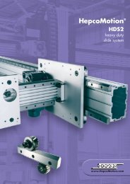
HepcoMotion ®<br />
<strong>MCS</strong><br />
aluminium frame and<br />
machine construction<br />
system including<br />
MFS fencing<br />
system
<strong>MCS</strong> Machine Construction System and MFS Machine Fencing System<br />
Contents<br />
Contents<br />
Page<br />
Introduction 1<br />
Application Examples 2<br />
Details of Hepco’s 3D Design Package 3<br />
Aluminium Profiles – Structural Sections 4-15<br />
Profile Connections 16-24<br />
Accessories 25-34<br />
MFS - Fencing System 35-40<br />
Specialist Sections 41-43<br />
Technical Details 44-53<br />
Aluminium Profile Technical Specification<br />
Deflection Calculations<br />
Moment of Inertia, Section Modulus and Mass of <strong>MCS</strong> System<br />
Choosing the correct <strong>MCS</strong> System Profile for your application<br />
Profile Connection Carrying Capacity<br />
Connection Cross Reference Chart<br />
Assembly Hints<br />
Machining Details<br />
Profiles with Linear Slide options 54-64<br />
Alphabetical Index 65<br />
How the Hepco <strong>MCS</strong> System saves Time and Money<br />
WELDED STEEL<br />
FRAMEWORK<br />
<strong>MCS</strong> MACHINE<br />
CONSTRUCTION SYSTEM<br />
350 minutes 100 minutes<br />
Component files can be downloaded from Hepco’s website www.HepcoMotion.com
Introduction<br />
Introduction<br />
The HepcoMotion <strong>MCS</strong> System offers an extensive range of aluminium profile sections plus all the<br />
connecting elements and accessories the designer could need. These modular components allow an<br />
almost infinite possibility of frames to be constructed for use in industrial machinery, guarding, storage<br />
and display applications.<br />
The latest addition to the product range is Hepco’s MFS – Machine Fencing System (see page 35).<br />
Fully compatible with the <strong>MCS</strong> ranges it provides economical barriers around machine installations<br />
such as gantries, pick and place equipment, floor mounted robot systems or any areas where the<br />
exclusion of personnel is required.<br />
Profile machining and frame assembly to customer’s drawings is carried out by Hepco with fast<br />
deliveries. Alternatively, specific cut or random lengths can be supplied to customers enabling<br />
construction of their own system. Frame design and specification is aided by the use of the <strong>MCS</strong> CAD<br />
3D files, available in .dwg and .dxf formats.<br />
Aluminium profiles are manufactured from AI6063-T5 to very close tolerances, and clear coat anodised<br />
to a depth of 10 microns, ensuring that frames are both accurate and resistant to scratching or<br />
corrosion. All manufacture is covered by full ISO 9001 certification.<br />
The <strong>MCS</strong> System is particularly effective at replacing traditional welded steel structures at lower overall<br />
cost due to the massive time saving involved. Flexibility is increased compared to welded structures,<br />
since all elements are re-usable and additions can easily be made to existing designs at any time. Many<br />
of the brackets and connecting elements in the <strong>MCS</strong> System can be used with no machining involved,<br />
for maximum simplicity.<br />
Hepco’s extensive range of linear systems can also be mounted directly onto the <strong>MCS</strong> Profile sections<br />
and can be pre assembled in our factory to ensure parallelism. Additional accessories including sliding<br />
door systems, locks, etc., are available on request.<br />
A full range of polycarbonate panels, clear and coloured, compressed foam panels in various colours<br />
as well as welded wire mesh panels – self coloured or powder coated – are available to complete your<br />
framework design.<br />
Please contact our Technical Sales Team on 01884 257000 for further details.<br />
Symbols used in this Catalogue<br />
8<br />
Size of profile T-Slot – specify connecting components to suit<br />
M8<br />
Profile End Tapping Size<br />
Components compatible with other systems. Contact Hepco for details.<br />
The full range of HepcoMotion products can be seen on our website: www.HepcoMotion.com<br />
Component files can be downloaded from Hepco’s website www.HepcoMotion.com 1
<strong>MCS</strong> Machine Construction System and MFS Machine Fencing System<br />
Application Examples<br />
Areas of Application<br />
• Special Purpose Machines<br />
• Work Benches<br />
• Robotic and Manipulating Systems<br />
• Machine Guards/Protective Frameworks<br />
• Fencing and Enclosures<br />
• Assembly and Packaging Machinery<br />
• Exhibition Display Units<br />
• Shelving Systems<br />
CAD Frame Drawings<br />
Exhibition Units<br />
Special Purpose Machines<br />
Access Frameworks<br />
MFS – Machine Fencing System<br />
2<br />
Component files can be downloaded from Hepco’s website www.HepcoMotion.com
CAD Frame Drawings<br />
3D Design Package<br />
To provide our customers with a fully detailed<br />
quotation, Hepco is able to produce full <strong>MCS</strong> CAD<br />
drawings and 3D views to customer’s specification<br />
and design. Its fully itemised parts list and<br />
schedule is also supplied where<br />
customers are assembling<br />
frameworks themselves.<br />
Component files can be downloaded from Hepco’s website www.HepcoMotion.com 3
<strong>MCS</strong> Machine Construction System and MFS Machine Fencing System<br />
Structural Sections<br />
Aluminium Profiles<br />
Structural Sections<br />
20 x 20<br />
see page 6<br />
20 x 40<br />
see page 6<br />
30 x 30<br />
see page 6<br />
30 x 60<br />
see page 6<br />
30 x 90<br />
see page 7<br />
40 x 40SL<br />
see page 7<br />
40 x 40L<br />
see page 7<br />
40 x 40<br />
see page 7<br />
40 x 40 – 1NS<br />
see page 8<br />
40 x 40 – 2NS<br />
see page 8<br />
40LR<br />
see page 8<br />
40 x 80L<br />
see page 8<br />
40 x 80<br />
see page 9<br />
40 x 80 – 2NS<br />
see page 9<br />
40 x 80 – 3NS<br />
see page 9<br />
45 x 45SL<br />
see page 9<br />
45 x 45L<br />
see page 10<br />
45 x 45<br />
see page 10<br />
45 x 45 – 1NS<br />
see page 10<br />
45 x 45 – 2NS<br />
see page 10<br />
45LR<br />
see page 11<br />
45˚<br />
see page 11<br />
45 x 60L<br />
see page 11<br />
45 x 60<br />
see page 11<br />
45 x 90L<br />
see page 12<br />
45 x 90<br />
see page 12<br />
45 x 90 – 2NS<br />
see page 12<br />
45 x 90 – 3NS<br />
see page 12<br />
60 x 60L<br />
see page 13<br />
60 x 60<br />
see page 13<br />
4<br />
Component files can be downloaded from Hepco’s website www.HepcoMotion.com
Structural Sections<br />
Aluminium Profiles<br />
Structural Sections<br />
60 x 90<br />
see page 13<br />
80 x 80SL<br />
see page 13<br />
80 x 80L<br />
see page 14<br />
80 x 80<br />
see page 14<br />
80 x 80 – 2NS<br />
see page 14<br />
80 x 80 – 4NS<br />
see page 14<br />
80 x 120<br />
see page 15<br />
80 x 160<br />
see page 15<br />
90 x 90L<br />
see page 15<br />
90 x 90<br />
see page 15<br />
See specialist section page 41 for other profiles.<br />
These structural aluminium profiles are precision extruded using high quality AI6063-T5 material.<br />
They are then clear-coat anodised to a thickness of 10 microns, resulting in an accurate, hard-wearing<br />
basis for all types of frame construction.<br />
Profiles can also be specially powder coated in a range of colours.<br />
All profiles include T-slots along their length, allowing simple insertion of T-nuts and T-bolts to attach<br />
connection brackets or accessories.<br />
Most sizes of structural profile are available as random 5600mm lengths, with the exception of the<br />
20x20, 20x40 and 90x90 sizes 4000mm. A fast cutting, drilling, machining and tapping service is<br />
provided by Hepco, which also includes complete frame assembly to customer's drawings. See page<br />
53 for end machining details.<br />
For details of 'Choosing the correct <strong>MCS</strong> System profile for your application' please refer to<br />
pages 48 to 49. Complete Technical details may be found on pages 44 to 53.<br />
Component files can be downloaded from Hepco’s website www.HepcoMotion.com 5
<strong>MCS</strong> Machine Construction System and MFS Machine Fencing System<br />
Structural Sections<br />
Aluminium Profiles<br />
20 x 20<br />
0-132-2020<br />
6<br />
M5<br />
20 x 40<br />
0-132-2040<br />
6<br />
M5<br />
20<br />
20<br />
Ø4.3<br />
12<br />
Ø4.3<br />
12<br />
20<br />
40<br />
6 7<br />
20<br />
6 7<br />
30 x 30<br />
0-132-3030<br />
8<br />
M8<br />
30 x 60<br />
0-132-3060<br />
8<br />
M8<br />
30<br />
30<br />
Ø6.8<br />
18<br />
Ø6.8<br />
18<br />
30<br />
60<br />
8 9 30<br />
8 9<br />
Technical Data<br />
20 x 20 20 x 40 30 x 30 30 x 60<br />
Max. Length 4000mm 4000mm 5600mm 5600mm<br />
Mass 0.44kg/m 0.77kg/m 0.97kg/m 1.83kg/m<br />
Moment of Inertia (cm 4 ) Ixx 0.7 Ixx 4.5 Ixx 3.4 Ixx 23.3<br />
Iyy 0.7 Iyy 1.2 Iyy 3.4 Iyy 6.1<br />
Section Modulus (cm 3 ) Wxx 0.7 Wxx 2.2 Wxx 2.2 Wxx 7.8<br />
Wyy 0.7 Wyy 1.2 Wyy 2.2 Wyy 4.1<br />
6<br />
Component files can be downloaded from Hepco’s website www.HepcoMotion.com<br />
For key reference see page 1
Structural Sections<br />
Aluminium Profiles<br />
30 x 90<br />
0-132-3090<br />
8<br />
M8<br />
40 x 40SL<br />
0-132-4042<br />
10<br />
M12<br />
Ø6.8<br />
40<br />
20<br />
Ø10<br />
10 12<br />
40<br />
40 x 40<br />
0-132-4040<br />
10<br />
M12<br />
40 x 40L<br />
0-132-4041<br />
10<br />
M12<br />
40<br />
20<br />
Ø10<br />
40<br />
20<br />
Ø10<br />
10 12 40<br />
10<br />
12 40<br />
Technical Data<br />
30 x 90 40 x 40SL 40 x 40L 40 x 40<br />
Max. Length 5600mm 5600mm 5600mm 5600mm<br />
Mass 2.57kg/m 1.2kg/m 1.4kg/m 1.9kg/m<br />
Moment of Inertia (cm 4 ) Ixx 74.4 Ixx 7.2 Ixx 8.2 Ixx 11.1<br />
Iyy 9.2 Iyy 7.2 Iyy 8.2 Iyy 11.1<br />
Section Modulus (cm 3 ) Wxx 16.5 Wxx 3.9 Wxx 4.1 Wxx 5.6<br />
Wyy 6.1 Wyy 3.9 Wyy 4.1 Wyy 5.6<br />
Component files can be downloaded from Hepco’s website www.HepcoMotion.com For key reference see page 1 7
<strong>MCS</strong> Machine Construction System and MFS Machine Fencing System<br />
Structural Sections<br />
Aluminium Profiles<br />
40 x 40 – 1NS<br />
0-132-4001<br />
10<br />
M12<br />
40 x 40 – 2NS<br />
0-132-4002<br />
10<br />
M12<br />
40<br />
Ø10<br />
40<br />
20<br />
20<br />
Ø10<br />
10 12 40<br />
10 12 40<br />
40LR<br />
0-132-4000<br />
10<br />
M12<br />
40 x 80L<br />
0-132-4081<br />
10<br />
M12<br />
40<br />
20<br />
40<br />
Ø10<br />
R40<br />
12<br />
10<br />
Ø10<br />
10<br />
12<br />
30 40 80<br />
2.4<br />
20 40<br />
10<br />
12<br />
Technical Data<br />
40 x 40 – 1NS 40 x 40 – 2NS 40LR 40 x 80L<br />
Max. Length 5600mm 5600mm 5600mm 5600mm<br />
Mass 1.7kg/m 1.7kg/m 1.2kg/m 2.1kg/m<br />
Moment of Inertia (cm 4 ) Ixx 10.2 Ixx 10.2 Ixx 6.0 Ixx 51.2<br />
Iyy 9.8 Iyy 10.2 Iyy 6.0 Iyy 14.2<br />
Section Modulus (cm 3 ) Wxx 5.1 Wxx 5.1 Wxx 2.4 Wxx 25.6<br />
Wyy 4.9 Wyy 5.1 Wyy 2.4 Wyy 3.6<br />
8<br />
Component files can be downloaded from Hepco’s website www.HepcoMotion.com<br />
For key reference see page 1
Structural Sections<br />
Aluminium Profiles<br />
40 x 80<br />
0-132-4080<br />
10<br />
M12<br />
40 x 80 – 2NS<br />
0-132-4082<br />
10<br />
M12<br />
40<br />
Ø10<br />
40<br />
10<br />
Ø10<br />
20<br />
40<br />
80<br />
40 80<br />
10 12<br />
40 x 80 – 3NS<br />
0-132-4083<br />
10<br />
M12<br />
45 x 45SL<br />
0-132-4547<br />
10<br />
M12<br />
40<br />
10<br />
Ø10<br />
45<br />
Ø10<br />
40 80<br />
10 12<br />
45<br />
10 20<br />
Technical Data<br />
40 x 80 40 x 80 – 2NS 40 x 80 – 3NS 45 x 45SL<br />
Max. Length 5600mm 5600mm 5600mm 5600mm<br />
Mass 2.62kg/m 2.8kg/m 2.8kg/m 1.4kg/m<br />
Moment of Inertia (cm 4 ) Ixx 61.2 Ixx 67.1 Ixx 65.8 Ixx 10.0<br />
Iyy 17.0 Iyy 18.3 Iyy 18.0 Iyy 10.0<br />
Section Modulus (cm 3 ) Wxx 15.3 Wxx 16.7 Wxx 16.45 Wxx 4.4<br />
Wyy 8.5 Wyy 9.15 Wyy 9.0 Wyy 4.4<br />
Component files can be downloaded from Hepco’s website www.HepcoMotion.com For key reference see page 1 9
<strong>MCS</strong> Machine Construction System and MFS Machine Fencing System<br />
Structural Sections<br />
Aluminium Profiles<br />
45 x 45L<br />
0-132-4546<br />
10<br />
M12<br />
45 x 45<br />
0-132-4545<br />
10<br />
M12<br />
45<br />
20<br />
O10<br />
45<br />
20<br />
Ø10<br />
10 12 45<br />
10 12 45<br />
45 x 45 – 1NS<br />
0-132-4501<br />
10<br />
M12<br />
45 x 45 – 2NS<br />
0-132-4502<br />
10<br />
M12<br />
45<br />
20<br />
Ø10<br />
45<br />
20<br />
Ø10<br />
10 12 45<br />
10 12 45<br />
Technical Data<br />
45 x 45L 45 x 45 45 x 45 – 1NS 45 x 45 – 2NS<br />
Max. Length 5600mm 5600mm 5600mm 5600mm<br />
Mass 1.5kg/m 1.9kg/m 1.9kg/m 1.8kg/m<br />
Moment of Inertia (cm 4 ) Ixx 10.4 Ixx 13.4 Ixx 13.0 Ixx 12.7<br />
Iyy 10.4 Iyy 13.4 Iyy 13.0 Iyy 12.7<br />
Section Modulus (cm 3 ) Wxx 4.6 Wxx 6.0 Wxx 5.9 Wxx 5.6<br />
Wyy 4.6 Wyy 6.0 Wyy 5.9 Wyy 5.6<br />
10<br />
Component files can be downloaded from Hepco’s website www.HepcoMotion.com<br />
For key reference see page 1
Structural Sections<br />
Aluminium Profiles<br />
45LR<br />
0-132-4500<br />
10<br />
M12<br />
45˚<br />
1-242-4700<br />
10<br />
M12<br />
45<br />
22.5<br />
20<br />
R45<br />
12<br />
10 Ø10<br />
R45<br />
45<br />
22.5<br />
(50.05)<br />
20<br />
22.5<br />
45<br />
20<br />
Ø10<br />
22.5<br />
10<br />
45<br />
45 x 60L<br />
0-132-4561<br />
10<br />
M12<br />
45 x 60<br />
0-132-4560<br />
10<br />
M12<br />
45<br />
20<br />
Ø10<br />
45<br />
20<br />
Ø10<br />
10 12 60<br />
10<br />
12 60<br />
Technical Data<br />
45LR 45˚ 45 x 60L 45 x 60<br />
Max. Length 5600mm 5600mm 5600mm 5600mm<br />
Mass 1.3kg/m 2.6kg/m 2.15kg/m 2.8kg/m<br />
Moment of Inertia (cm 4 ) Ixx 7.6 Ixx 10.4 Ixx 24.0 Ixx 34.2<br />
Iyy 7.6 Iyy 9.6 Iyy 15.1 Iyy 21.6<br />
Section Modulus (cm 3 ) Wxx 3.4 Wxx 4.0 Wxx 8.0 Wxx 11.4<br />
Wyy 3.4 Wyy 3.96 Wyy 6.7 Wyy 9.6<br />
Component files can be downloaded from Hepco’s website www.HepcoMotion.com For key reference see page 1 11
<strong>MCS</strong> Machine Construction System and MFS Machine Fencing System<br />
Structural Sections<br />
Aluminium Profiles<br />
45 x 90L<br />
0-132-4591<br />
10<br />
M12<br />
45 x 90<br />
0-132-4590<br />
10<br />
M12<br />
45<br />
Ø10<br />
45<br />
Ø10<br />
20<br />
20<br />
45<br />
90<br />
45<br />
90<br />
10 12<br />
10 12<br />
45 x 90 – 2NS<br />
0-132-4592<br />
10<br />
M12<br />
45 x 90 – 3NS<br />
0-132-4593<br />
10<br />
M12<br />
45<br />
Ø10<br />
45<br />
Ø10<br />
20<br />
20<br />
45<br />
90<br />
45 90<br />
10 12<br />
10 12<br />
Technical Data<br />
45 x 90L 45 x 90 45 x 90 – 2NS 45 x 90 – 3NS<br />
Max. Length 5600mm 5600mm 5600mm 5600mm<br />
Mass 3.15kg/m 3.6kg/m 3.4kg/m 3.4kg/m<br />
Moment of Inertia (cm 4 ) Ixx 92.6 Ixx 100.0 Ixx 96.0 Ixx 94.0<br />
Iyy 22.1 Iyy 28.5 Iyy 29.0 Iyy 28.0<br />
Section Modulus (cm 3 ) Wxx 20.6 Wxx 22.2 Wxx 21.3 Wxx 20.9<br />
Wyy 9.8 Wyy 12.7 Wyy 12.9 Wyy 12.4<br />
12 Component files can be downloaded from Hepco’s website www.HepcoMotion.com<br />
For key reference see page 1
Structural Sections<br />
Aluminium Profiles<br />
60 x 60L<br />
0-132-6061<br />
10<br />
M12<br />
60 x 60<br />
0-132-6060<br />
10<br />
M12<br />
60<br />
10<br />
Ø10<br />
60<br />
20<br />
Ø10<br />
10 12 60<br />
10 12 60<br />
60 x 90<br />
0-132-6090<br />
10<br />
M12<br />
80 x 80SL<br />
0-132-8082<br />
10<br />
M12<br />
60<br />
10<br />
80<br />
40<br />
Ø10<br />
10 12<br />
90<br />
40 80<br />
20<br />
10 12<br />
Technical Data<br />
60 x 60L 60 x 60 60 x 90 80 x 80SL<br />
Max. Length 5600mm 5600mm 5600mm 5600mm<br />
Mass 2.88kg/m 3.7kg/m 4.35kg/m 3.6kg/m<br />
Moment of Inertia (cm 4 ) Ixx 37.0 Ixx 47 Ixx 128.4 Ixx 11.1<br />
Iyy 37.0 Iyy 47 Iyy 60.1 Iyy 11.1<br />
Section Modulus (cm 3 ) Wxx 12.3 Wxx 15.7 Wxx 28.5 Wxx 5.6<br />
Wyy 12.3 Wyy 15.7 Wyy 20.0 Wyy 5.6<br />
Component files can be downloaded from Hepco’s website www.HepcoMotion.com For key reference see page 1 13
<strong>MCS</strong> Machine Construction System and MFS Machine Fencing System<br />
Structural Sections<br />
Aluminium Profiles<br />
80 x 80L<br />
0-132-8081<br />
10<br />
M12<br />
80 x 80<br />
0-132-8080<br />
10<br />
M12<br />
80<br />
80<br />
40<br />
Ø10<br />
40<br />
Ø10<br />
20<br />
20<br />
80<br />
80<br />
10 12<br />
10<br />
12<br />
80 x 80 – 2NS<br />
0-132-8001<br />
10<br />
M12<br />
80 x 80 – 4NS<br />
0-132-8002<br />
10<br />
M12<br />
80<br />
40<br />
10<br />
Ø10<br />
80<br />
40<br />
Ø10<br />
10<br />
40<br />
80<br />
40 80<br />
Technical Data<br />
80 x 80L 80 x 80 80 x 80 – 2NS 80 x 80 – 4NS<br />
Max. Length 5600mm 5600mm 5600mm 5600mm<br />
Mass 4.1kg/m 4.94kg/m 3.7kg/m 3.7kg/m<br />
Moment of Inertia (cm 4 ) Ixx 110.4 Ixx 132.5 Ixx 100 Ixx 104<br />
Iyy 110.4 Iyy 132.5 Iyy 102 Iyy 104<br />
Section Modulus (cm 3 ) Wxx 27.6 Wxx 33.1 Wxx 25 Wxx 26<br />
Wyy 27.6 Wyy 33.1 Wyy 25 Wyy 26<br />
14 Component files can be downloaded from Hepco’s website www.HepcoMotion.com<br />
For key reference see page 1
Structural Sections<br />
Aluminium Profiles<br />
80 x 120<br />
0-132-80120<br />
10<br />
M12<br />
80 x 160<br />
0-132-80160<br />
10<br />
M12<br />
10<br />
80<br />
12<br />
Ø10<br />
80<br />
40<br />
Ø10<br />
20<br />
40<br />
40<br />
40<br />
120<br />
40<br />
160<br />
40<br />
40<br />
10 12<br />
90 x 90L<br />
0-132-9091<br />
10<br />
M12<br />
90 x 90<br />
0-132-9090<br />
10<br />
M16<br />
90<br />
90<br />
45<br />
Ø10<br />
45<br />
Ø14<br />
20<br />
20<br />
45<br />
90<br />
45<br />
90<br />
10 12<br />
10 12<br />
Technical Data<br />
80 x 120 80 x 160 90 x 90L 90 x 90<br />
Max. Length 5600mm 5600mm 5600mm 4000mm<br />
Mass 6.4kg/m 9.1kg/m 5.6kg/m 9.3kg/m<br />
Moment of Inertia (cm 4 ) Ixx 362 Ixx 890 Ixx 190 Ixx 285<br />
Iyy 176 Iyy 262 Iyy 190 Iyy 285<br />
Section Modulus (cm 3 ) Wxx 90 Wxx 111 Wxx 42 Wxx 63<br />
Wyy 29 Wyy 65 Wyy 42 Wyy 63<br />
Component files can be downloaded from Hepco’s website www.HepcoMotion.com For key reference see page 1 15
<strong>MCS</strong> Machine Construction System and MFS Machine Fencing System<br />
Profile Connections<br />
Profile Connections<br />
Flexi Connector (A)<br />
see page 17<br />
Flexi Connector (B)<br />
see page 17<br />
Flexi Angle Connector<br />
see page 17<br />
Flexi Mitre Connector<br />
see page 17<br />
Flexi Straight<br />
Connector<br />
see page 17<br />
Flexi Threaded<br />
Connector<br />
see page 17<br />
Flexi Connector<br />
End Cap<br />
see page 17<br />
Connection Screw<br />
see page 18<br />
T-Bolt & Flange Nut<br />
see page 18<br />
T-Nut<br />
see page 19<br />
Sprung Loaded T-Nut<br />
see page 19<br />
Angled Nut<br />
see page 19<br />
Slot Block<br />
see page 20<br />
Connector Link Set<br />
see page 20<br />
Bolt Connector Set<br />
see page 20<br />
Bracket 17 x 25<br />
see page 20<br />
Bracket 20 x 28<br />
see page 21<br />
Bracket 36 x 36<br />
see page 21<br />
Bracket 42 x 43<br />
see page 21<br />
Bracket 42 x 88<br />
see page 21<br />
Bracket 57 x 57<br />
see page 22<br />
Bracket 75 x 75<br />
see page 22<br />
Bracket 88 x 88<br />
see page 22<br />
Angle Bracket<br />
see page 22<br />
Interior Bracket (A)<br />
see page 23<br />
Interior Bracket (B)<br />
see page 23<br />
Knuckle Joints<br />
see page 23<br />
End Connector Set<br />
see page 24<br />
Flexi Connector<br />
Drill Jig<br />
see page 24<br />
180˚<br />
16<br />
Component files can be downloaded from Hepco’s website www.HepcoMotion.com
Profile Connections<br />
Flexi Connectors<br />
For maximum versatility, profile position adjustment and<br />
speedy assembly simply drill dimension ‘C’ to suit the<br />
relevant profile with 15.1mm Ø drill available from<br />
Hepco, Part No. 1-243-5556.<br />
Please note:<br />
(40) refers to profiles of cross-sections 40, 80 & 160mm,<br />
(45) refers to profiles of cross-section 45, 60 & 90mm.<br />
Materials are zinc plated SM20C steel.<br />
Two Position 90˚ and 45˚ Drilling Jig available<br />
(see page 24).<br />
Order with Ball End Allen Key, Part No. 1-243-5555<br />
Flexi T Connector (A)<br />
(40) 1-242-4549 (45)1-242-4550<br />
Flexi T Connector end cap – for all versions<br />
1-243-0048<br />
22.5<br />
20<br />
SNAP-OFF PORTION<br />
Flexi T Connector (B)<br />
(40) 1-242-4551 (45)1-242-4552<br />
(40) C = 20<br />
(45) C = 22.5<br />
"C"<br />
(40) C = 20<br />
(45) C = 22.5<br />
"C"<br />
Flexi Angle Connector<br />
(40) 1-242-4553 (45)1-242-4554<br />
Flexi Mitre Connector<br />
(40) 1-242-4555 (45)1-242-4556<br />
(40) C = 32<br />
(45) C = 30<br />
"C"<br />
(40) C = 30<br />
(45) C = 30<br />
"C"<br />
"C"<br />
Flexi Straight Connector<br />
(40) 1-242-4557 (45)1-242-4558<br />
Flexi Threaded Connector<br />
(40) 1-242-4559 (45)1-242-4560<br />
(40) C = 22.5<br />
(45) C = 22.5<br />
"C"<br />
"C"<br />
(40) C = 20<br />
(45) C = 22.5<br />
Base plate<br />
"C"<br />
Component files can be downloaded from Hepco’s website www.HepcoMotion.com 17
<strong>MCS</strong> Machine Construction System and MFS Machine Fencing System<br />
Profile Connections<br />
Connection Screw<br />
1-242-1033 M5 x 20<br />
1-242-1034 M8 x 30<br />
1-242-1005 M12 x 30<br />
New self tapping screw for all<br />
10mm T-slot connections<br />
1-242-1011 S12 x 30<br />
6<br />
8 Ø14<br />
10<br />
Ø19.4<br />
Ø10.5<br />
5 A/F<br />
8 A/F<br />
4 A/F<br />
20<br />
30<br />
23<br />
30<br />
36<br />
M5<br />
M8<br />
M12<br />
T-Bolt & Flange Nut<br />
10<br />
7.8<br />
8.5<br />
18.2<br />
T-Bolt<br />
1-242-1009 M8 x 25L<br />
1-242-1000 M8 x 30L<br />
1-242-1010 M8 x 38L<br />
1-242-1006 M8 x 45L<br />
Flange Nut<br />
1-242-1101 M8 x 12 A/F<br />
1-242-1100 M8 x 14 A/F<br />
9<br />
M8<br />
Max. Plate Thickness<br />
using the following T-Bolts and Flange Nuts:<br />
L<br />
12 A/F* 14 A/F*<br />
M8 x 25L 5.5mm 3.5mm<br />
M8 x 30L 10.5mm 8.5mm<br />
M8 x 45L 25.5mm 23.5mm<br />
5.5<br />
9.6<br />
* Dimension difference of 2mm is due to differing T-Slot<br />
dimensions between profile sizes<br />
Technical Data<br />
Connection Screw<br />
T-Bolt & Flange Nut<br />
Material Steel EN3B Steel EN3B<br />
Finish Zinc Plated Zinc Plated<br />
Mass 1-242-1033 0.01kg/ea 1-242-1009 0.01kg/ea<br />
1-242-1034 0.01kg/ea 1-242-1000 0.01kg/ea<br />
1-242-1005 0.01kg/ea 1-242-1010 0.02kg/ea<br />
1-242-1011 0.02kg/ea 1-242-1006 0.02kg/ea<br />
18 Component files can be downloaded from Hepco’s website www.HepcoMotion.com<br />
For key reference see page 1
Profile Connections<br />
T-Nuts<br />
1.2<br />
1.4<br />
4<br />
6.2<br />
6<br />
11<br />
5.9<br />
8<br />
16.3<br />
7.9<br />
5.9<br />
7.9<br />
1-242-1022 M3 (slot 6)<br />
1-242-1023 M4 (slot 6)<br />
3.1<br />
1-242-1024 M4 (slot 8)<br />
1-242-1025 M5 (slot 8)<br />
1-242-1026 M6 (slot 8)<br />
8.7<br />
10<br />
19.5<br />
9.8<br />
9.7<br />
1-242-1029 M4 (slot 10)<br />
1-242-1030 M5 (slot 10)<br />
1-242-1001 M6 (slot 10)<br />
1-242-1002 M8 (slot 10)<br />
Sprung Loaded T-Nuts<br />
10<br />
Angled Nut<br />
8<br />
15<br />
2 x 45˚ CHAMFER<br />
-M-<br />
20<br />
M5, M6 TAP<br />
16<br />
9.8<br />
2<br />
6<br />
45˚<br />
7.7<br />
1-242-1007 M5<br />
1-242-1008 M6<br />
Spring-steel plate<br />
1-242-1061 M5 (slot 10)<br />
1-242-1062 M6 (slot 10)<br />
1-242-1063 M8 (slot 10)<br />
4.5<br />
Technical Data<br />
6 T-Nut 8 T-Nut 10 T-Nut Sprung Loaded Angled<br />
T-Nuts<br />
Nut<br />
Material Steel EN3B Steel EN3B Steel EN3B Steel EN3B Steel EN3B<br />
Finish Zinc Plated Zinc Plated Zinc Plated Zinc Plated Zinc Plated<br />
Mass 0.002kg/ea 0.004kg/ea 0.007kg/ea 0.013kg/ea 0.002kg/ea<br />
Component files can be downloaded from Hepco’s website www.HepcoMotion.com For key reference see page 1 19
<strong>MCS</strong> Machine Construction System and MFS Machine Fencing System<br />
Profile Connections<br />
Slot Block<br />
10<br />
Connector Link Set<br />
1-242-1020 S<br />
10<br />
1-242-1031 M5 (slot 10)<br />
1-242-1013 M6 (slot 10)<br />
1-242-1032 M8 (slot 10)<br />
Set comprises two<br />
connector links and is<br />
supplied with fixing screws.<br />
10.6<br />
20<br />
5.5 10<br />
9.8 19.5<br />
65<br />
180<br />
30 65 10<br />
19.5<br />
5.5<br />
10.5<br />
9.5<br />
4 HOLES M8<br />
Bolt Connector Set<br />
10<br />
Bracket 17 x 25<br />
1-242-1725<br />
6<br />
1-242-1004 S 20 x 39L<br />
Use with 40 x 40 and 40 x 80 profile<br />
1-242-2021 S 20 x 59L<br />
Use with 60 x 60 profile<br />
Supplied complete with fixing screws<br />
and T-Nuts<br />
39<br />
7.5<br />
14<br />
Note: Customer to supply<br />
2 of M4 x 10, 10Nm cap<br />
head screw and use with<br />
M4 T-Nut 1-242-1023<br />
17<br />
5.2 3<br />
9<br />
14<br />
Ø20<br />
59<br />
7.5<br />
14<br />
4<br />
25<br />
9 14<br />
Ø20<br />
3<br />
Technical Data<br />
Slot Block Connector Link Set Bolt Connector Set Bracket 17x25<br />
Material Steel EN3B Steel EN3B Steel EN3B Aluminium<br />
Finish Zinc Plated Zinc Plated Zinc Plated None<br />
Mass 0.02kg/ea 0.38kg/ea 39L 0.05kg/ea 0.02kg/ea<br />
59L 0.10kg/ea<br />
20 Component files can be downloaded from Hepco’s website www.HepcoMotion.com<br />
For key reference see page 1
Profile Connections<br />
Bracket 20 x 28<br />
1-242-2028<br />
8<br />
Bracket 36 x 36<br />
1-242-3636<br />
10<br />
Note: Customer to supply 2 of M6 x 10, 10 Nm cap head<br />
screw and use with T-Nut 1-242-1026<br />
Note: Use with T-Bolt M8 x 30L 1-242-1000 and<br />
Flange Nut M8 x 12 A/F 1-242-1101<br />
20<br />
6.3<br />
4.9<br />
36<br />
9<br />
8<br />
28<br />
4<br />
28<br />
15<br />
6<br />
25<br />
36<br />
36<br />
28<br />
36<br />
Bracket 42 x 43<br />
1-242-4243<br />
10<br />
Bracket 42 x 88<br />
1-242-4288<br />
10<br />
Note: Use with T-Bolt M8 x 30L 1-242-1000 and<br />
Flange Nut M8 x 12 A/F 1-242-1101<br />
Note: Use with T-Bolt M8 x 30L<br />
1-242-1000 and<br />
Flange Nut M8 x 12 A/F<br />
1-242-1101<br />
8.2<br />
43<br />
10.3<br />
8.7<br />
12<br />
31<br />
42<br />
9<br />
42<br />
45<br />
22.5<br />
67.5<br />
2-Ø8.5<br />
HOLES<br />
8.5<br />
42<br />
88<br />
88<br />
11<br />
Technical Data<br />
Bracket 20 x 28 36 x 36 42 x 43 42 x 88<br />
Material Aluminium Aluminium Aluminium Aluminium<br />
Finish None None None None<br />
Mass 0.02kg/ea 0.04kg/ea 0.06kg/ea 0.15kg/ea<br />
Component files can be downloaded from Hepco’s website www.HepcoMotion.com For key reference see page 1 21
<strong>MCS</strong> Machine Construction System and MFS Machine Fencing System<br />
Profile Connections<br />
Bracket 57 x 57<br />
1-242-5757<br />
Note:<br />
60 x 60 profile<br />
Use with T-Bolt M8 x 30L 1-242-1000<br />
and Flange Nut M8 x 12 A/F 1-242-1101<br />
Bracket 75 x 75<br />
10 10<br />
1-242-7575<br />
Note: Use with T-Bolt M8 x 30L 1-242-1000<br />
and Flange Nut M8 x 12 A/F 1-242-1101<br />
30x60 profile<br />
Customer to supply 8 of M6 x 16,<br />
10Nm csk head screw and use with T-Nut 1-242-1026<br />
8<br />
Ø6.6<br />
8.2<br />
8<br />
Ø9 HOLE<br />
40<br />
8<br />
30<br />
15<br />
20<br />
20<br />
57<br />
40<br />
20<br />
20<br />
75<br />
30<br />
75<br />
9<br />
Bracket 88 x 88<br />
1-242-8888<br />
10<br />
Angle Bracket<br />
1-242-1018S<br />
10<br />
Note: Use with T-Bolt M8 x 30L 1-242-1000<br />
and Flange Nut M8 x 12 A/F 1-242-1101<br />
Supplied as a set with fixing screws and T-Nuts<br />
40<br />
2-Ø8.5 thru<br />
(C/SUNK Ø16x90˚)<br />
10<br />
Ø9 HOLE<br />
45<br />
23<br />
43<br />
8<br />
23<br />
43<br />
45<br />
22.5<br />
22.5<br />
88<br />
88<br />
9<br />
Technical Data<br />
Bracket 57 x 57 75 x 75 88 x 88 Angle Bracket<br />
Material Aluminium Aluminium Aluminium Zinc Die-cast<br />
Finish None None None None<br />
Mass 0.12kg/ea 0.25kg/ea 0.30kg/ea 0.10kg/ea<br />
22<br />
Component files can be downloaded from Hepco’s website www.HepcoMotion.com<br />
For key reference see page 1
Profile Connections<br />
Interior Bracket (A)<br />
1-242-1039<br />
10<br />
Interior Bracket (B)<br />
1-242-1040<br />
10<br />
38<br />
26<br />
9.8<br />
9 9<br />
32 22 5˚<br />
3<br />
38<br />
26<br />
9.8<br />
32 22 9 9<br />
5˚<br />
3<br />
3<br />
9 2 x M8<br />
19.5<br />
SET SCREW<br />
(supplied)<br />
9<br />
3<br />
19.5<br />
2 x M8<br />
SET SCREW<br />
(supplied)<br />
38<br />
24<br />
38<br />
24<br />
Knuckle Joints<br />
10<br />
M12<br />
Supplied as a set with all fixings required.<br />
1-242-4548 For use with 45 x 45 1-242-4570 For use with 45 x 60<br />
76 82<br />
76 82<br />
38<br />
38<br />
45 45<br />
45 60<br />
Technical Data<br />
Bracket Interior (B) Interior (A) Knuckle Joints<br />
Material Zinc Die-cast Zinc Die-cast Zinc Die-cast<br />
Finish None None None<br />
Mass 0.06kg/ea 0.06kg/ea 1-242-4548 0.54kg/set<br />
1-242-4570 0.62kg/set<br />
Component files can be downloaded from Hepco’s website www.HepcoMotion.com For key reference see page 1 23
<strong>MCS</strong> Machine Construction System and MFS Machine Fencing System<br />
Profile Connections<br />
End Connector Set<br />
1-242-4547S<br />
10<br />
M12<br />
Supplied in two parts with fixing screws. Location tabs may be easily removed where required.<br />
Material – Die-cast Zinc<br />
Mass – 0.45kg/set<br />
4 x M6 Bolt<br />
2 x M12 Bolt<br />
2 x 1-242-1001 T-nuts<br />
M12 Bolt<br />
2 x M6 Bolt<br />
45<br />
4 x M6 Nut<br />
45<br />
20<br />
Flexi Connector Drilling Jig 45˚ ends<br />
1-242-4561<br />
For speedy drilling when using mitre connectors or<br />
angle connectors at 45˚.<br />
Drilling jigs should be<br />
Ø15.1 ordered with Ø15.1 drill.<br />
Part No.<br />
1-243-5556<br />
Flexi Connector Drilling Jig 90˚ ends<br />
1-242-4562<br />
For speedy drilling for all 90˚ joint connectors.<br />
Ø15.1<br />
Drilling jigs should be<br />
ordered with Ø15.1 drill.<br />
Part No.<br />
1-243-5556<br />
45<br />
Supplied with<br />
two stops to<br />
suit 40 (45)<br />
10<br />
55<br />
45<br />
Multifunction<br />
end stop to<br />
suit 40 (45)<br />
36<br />
110<br />
Material –<br />
Steel with<br />
Black Oxide<br />
finish<br />
36<br />
110<br />
Material –<br />
Steel with<br />
Black Oxide<br />
finish<br />
24 Component files can be downloaded from Hepco’s website www.HepcoMotion.com<br />
For key reference see page 1
Accessories<br />
Accessories<br />
Feet<br />
see page 26<br />
Foot Plates<br />
see page 27<br />
Foundation Bracket<br />
see page 28<br />
Castors<br />
see page 29<br />
T-Slot Glazing Strip<br />
see page 30<br />
Panel Holder<br />
see page 30<br />
Panel Guide<br />
see page 30<br />
Cover Strip<br />
see page 31<br />
End Caps<br />
see page 31<br />
Hinge<br />
see page 32<br />
Handle<br />
see page 33<br />
Cable Clamp Block<br />
see page 34<br />
Panel Mounting Block<br />
see page 34<br />
Snap Hook<br />
see page 34<br />
Suspended Slide<br />
see page 34<br />
A extensive range of accessories for the <strong>MCS</strong> System provides professional frame finishing, allows sliding and<br />
hinged door hanging, suspension of work tools, adjustable feet for non-level floors, and location of glazing panels.<br />
These components are precision formed using PVC, ABS plastic, or coated steel for a hard-wearing and<br />
aesthetically-pleasing result.<br />
Hepco also offers a range of hard-wearing Castors to suit the <strong>MCS</strong> Machine Construction System –<br />
details of these are on page 29. Castors for more specialist uses can be easily sourced by Hepco – ask us for<br />
details if any of the standard range is not suitable for a particular application.<br />
Component files can be downloaded from Hepco’s website www.HepcoMotion.com 25
<strong>MCS</strong> Machine Construction System and MFS Machine Fencing System<br />
Accessories<br />
Foot<br />
M8<br />
M12<br />
M16<br />
Adjustable height with 15˚ of movement<br />
allows for uneven floor surfaces.<br />
Profile end requires tapping.<br />
M<br />
15˚<br />
15˚<br />
L<br />
Part No. Tap Size Diameter Length Mass<br />
1-243-0030 M8 40 60 0.04kg/ea.<br />
1-243-0050 M12 60 150 0.17kg/ea.<br />
1-243-0051 M12 100 150 0.23kg/ea.<br />
1-243-0040 M16 60 150 0.28kg/ea.<br />
1-243-0041 M16 100 150 0.33kg/ea.<br />
ø<br />
Steel Foot – cushioning type<br />
M8<br />
M12<br />
M16<br />
D<br />
Part No. D D1 L L1 L2 L3 Mass<br />
1-243-0020 8 40 63 40 6 17 0.85kg/ea.<br />
1-243-0021 12 48 152 125 8 19 0.15kg/ea.<br />
1-243-0022 16 61 155 125 10 20 0.2kg/ea.<br />
L1<br />
L<br />
L2<br />
L3<br />
D1<br />
Technical Data<br />
Foot<br />
Steel Foot<br />
Material Plastic and Steel Steel and Rubber<br />
Finish Steel/Zinc Plated Plated<br />
26 Component files can be downloaded from Hepco’s website www.HepcoMotion.com<br />
For key reference see page 1
Accessories<br />
Foot Plates<br />
ØD (C/Bore ØE x F)<br />
G<br />
Allows assembly of Foot on<br />
rectangular profiles, which have<br />
no central fixing hole.<br />
B<br />
C<br />
A<br />
H<br />
Part No. Recommended for A B C D E F G H Mass kg<br />
1-243-0114 20x40 20 40 20 5.5 9.5 5.4 M8 8 0.05<br />
1-243-0115 30x60 30 60 30 9 14 8.6 M8 12 0.17<br />
1-243-0116 40x80 40 80 40 13 20 13 M16 20 0.5<br />
1-243-0112 45x90 45 90 45 13 20 13 M16 20 0.5<br />
Allows assembly of Foot on<br />
square profiles, which have no<br />
G<br />
C<br />
B<br />
ØD (C/Bore ØE x F)<br />
H<br />
central fixing hole.<br />
B<br />
A<br />
Part No. Recommended for A B C D E F G H Mass kg<br />
1-243-0117 80x80 80 40 80 14 20 13 M16 20 1.0<br />
1-243-0113 90x90L 90 45 90 13 20 13 M16 20 1.0<br />
Technical Data<br />
Rectangular Foot Profile<br />
Square Foot Profile<br />
Material Steel EN32 Steel EN32<br />
Finish Black Oxide Black Oxide<br />
Component files can be downloaded from Hepco’s website www.HepcoMotion.com For key reference see page 1 27
<strong>MCS</strong> Machine Construction System and MFS Machine Fencing System<br />
Accessories<br />
Foundation Bracket<br />
1-242-1019<br />
10<br />
Rigidly fixes a frame to the floor –<br />
use in conjunction with foot to allow<br />
levelling before fixing.<br />
Order with:<br />
2 of M8 x 25L T-Bolt 1-242-1009<br />
2 of M8 x 14 A/F Flange Nut 1-242-1100<br />
21<br />
11<br />
17<br />
90<br />
15<br />
10<br />
Customer to supply floor fixing bolt.<br />
45<br />
20<br />
110<br />
9<br />
210<br />
140<br />
42<br />
30<br />
50<br />
Floor Bracket<br />
1-242-1019 F<br />
10<br />
10<br />
10<br />
25<br />
10<br />
15.5<br />
Ø8.4<br />
20<br />
20<br />
20<br />
160<br />
160<br />
100<br />
38<br />
20<br />
60<br />
Technical Data<br />
Foundation Bracket<br />
Floor Bracket<br />
Material Steel EN32 Zinc Die-cast<br />
Finish Black Oxide Black Powder Coated<br />
Mass 0.44kg/ea 0.46kg/ea<br />
28<br />
Component files can be downloaded from Hepco’s website www.HepcoMotion.com<br />
For key reference see page 1
Accessories<br />
Castors<br />
M12<br />
Swivel type. Through hole fixing makes these castors suitable for end fixing into profiles from 40x40L to 90x90L (using<br />
M12 cap head fixing screw). Other castors for profiles outside this range available on request, or see the flange fixing<br />
type below.<br />
C80T Without Brake<br />
C80TB With Brake<br />
Brake<br />
Ø13<br />
104<br />
36<br />
30<br />
40<br />
Swivel type. Flange plate fixing allows inboard mounting using the 9mm slots provided.<br />
C80F Without Brake<br />
C80FB With Brake<br />
100<br />
80<br />
76<br />
Brake<br />
80 60 53<br />
30°<br />
104<br />
9<br />
36<br />
30<br />
40<br />
Technical Data<br />
Castors C80T/TB C80F/FB<br />
Body Zinc Plated Steel Zinc Plated Steel<br />
Wheel Nylon Nylon<br />
Tyre Polyurethane Polyurethane<br />
Wheel Diameter 80mm 80mm<br />
Load Capacity 90kg/ea 90kg/ea<br />
Mass 0.65kg/ea 0.65kg/ea<br />
Component files can be downloaded from Hepco’s website www.HepcoMotion.com For key reference see page 1 29
<strong>MCS</strong> Machine Construction System and MFS Machine Fencing System<br />
Accessories<br />
8mm T-Slot Glazing Strip<br />
1-242-1056<br />
8<br />
10mm T-Slot Glazing Strip<br />
1-242-1057<br />
10<br />
2/4<br />
5/6<br />
5/6<br />
30<br />
10<br />
1-242-1057A<br />
40/80/160 sections<br />
1-242-1057B<br />
45/60/90 sections<br />
2 Strips for panels<br />
2mm to 4mm<br />
1 Strip for panels<br />
5mm to 6mm<br />
Panel Holder<br />
1-242-1045<br />
10<br />
Panel Guide<br />
1-242-1049<br />
8<br />
For use in profiles with slot size 10. The two part holder<br />
can be inserted into a pre-assembled frame and allows<br />
5mm panels to be inserted/removed in situ. Supplied in<br />
3m random length.<br />
For use in profiles with slot size 8. Requires panel and<br />
panel guide to be fitted during assembly of the<br />
structural frame. Supplied in 3m random length.<br />
21.5<br />
Panel<br />
10<br />
4.9<br />
Panel<br />
10<br />
7<br />
14<br />
9.6<br />
2.7<br />
8<br />
9<br />
9 12.8<br />
Technical Data<br />
T-Slot<br />
Glazing Strip<br />
Panel Holder<br />
Panel Guide<br />
Material Rubber PVC/Rubber ABS Plastic<br />
Finish Black Black Black<br />
Mass – 3000mm 3000mm<br />
Max. Length Cut to length – –<br />
30<br />
Component files can be downloaded from Hepco’s website www.HepcoMotion.com<br />
For key reference see page 1
Accessories<br />
Cover Strip<br />
Improves the appearance of the finished frames, protects T-slots from contamination<br />
and secures electrical cable. Push fit. Supplied in 3m random lengths.<br />
New Aluminium strips for 10mm slots.<br />
6 1-242-1037 8 1-242-1038 10<br />
For slot size 6<br />
For slot size 8<br />
1-242-1016<br />
For slot size 10<br />
Aluminium<br />
1-242-1054(40)<br />
1-242-1055(45)<br />
For slot size 10<br />
End Caps<br />
For use with Structural Profile Sections. Push fit.<br />
L1 x L2 t<br />
Part No.<br />
20 x 20 3 1-243-4049<br />
L1<br />
L2<br />
t<br />
20 x 40 3 1-243-4050<br />
30 x 30 4 1-243-4047<br />
30 x 60 4 1-243-4051<br />
30 x 90 4 1-243-4056<br />
40 x 40 4 1-243-4041<br />
40 x 80 4 1-243-4052<br />
40LR 4 1-243-4053<br />
45 x 45 4 1-243-4042<br />
45 x 60 4 1-243-4043<br />
45 x 90 4 1-243-4044<br />
45LR 4 1-243-4054<br />
60 x 60 4 1-243-4045<br />
80 x 80 4 1-243-4055<br />
80 x 160 4 1-243-4055x2<br />
90 x 90 4 1-243-4046<br />
Technical Data<br />
Cover Strip<br />
End Caps<br />
Material Aluminium or PVC ABS Plastic<br />
Finish Anodized/Black (other colours available) Black<br />
Max. Length 3000mm –<br />
Mass 0.04kg/m –<br />
Mass Aluminium 0.06kg/m –<br />
Component files can be downloaded from Hepco’s website www.HepcoMotion.com For key reference see page 1 31
<strong>MCS</strong> Machine Construction System and MFS Machine Fencing System<br />
Accessories<br />
Hinge (Plastic)<br />
8 10<br />
Supplied individually or as a set complete with all relevant T-Nuts,<br />
screws and fixings. To order the set append part no. with an ‘S’.<br />
B<br />
L<br />
A<br />
1-243-4048 (S)<br />
To hinge size 30 profiles (fixed type)<br />
1-243-4545 (S)<br />
To hinge size 45 profiles (fixed type)<br />
C<br />
1-243-4060 (S)<br />
To hinge size 30 profile to a size 45 profile (fixed type)<br />
(S): Complete with fixings<br />
D<br />
8<br />
9<br />
Part No. L A B C ØD ØE<br />
1-243-4048 61 35 17.5 40 6.2 8<br />
1-243-4545 90 50 25 40 6.2 10<br />
E<br />
1-243-4560 74.5 42.5 17.5/25 40 6.2 8/10<br />
Hinge (Die-cast)<br />
10<br />
All hinges supplied as a set complete with standard fixings.<br />
B<br />
C<br />
ØD<br />
ØE<br />
1-243-6074 (S) R/H 40x40<br />
1-243-6073 (S) L/H 40x40<br />
To hinge size 40 (lift off type<br />
see example page 37)<br />
1-243-7006 (S) R/H 45x45<br />
1-243-7005 (S) L/H 45x45<br />
To hinge size 45 (lift off type<br />
see example page 37)<br />
1-243-6070 (S)<br />
To hinge size 40 (fixed type)<br />
1-243-8085 (S)<br />
To hinge size 45 (fixed type)<br />
Part No. L A B C ØD ØE<br />
1-243-6073(S) 70 42 60 30 12 6.2<br />
A<br />
L<br />
1-243-6074(S) 70 42 60 30 12 6.2<br />
1-243-7005(S) 80 47 60 30 12 6.2<br />
1-243-7006(S) 80 47 60 30 12 6.2<br />
1-243-6070(S) 70 42 60 30 12 6.2<br />
1-243-8085(S) 80 47 60 30 12 6.2<br />
Technical Data<br />
Hinge Hinge 40 Hinge 45 Hinge Lift Off<br />
Material Nylon Zinc Die-cast Zinc Die-cast Zinc Die-cast<br />
Finish Black Chrome Plated Chrome Plated Chrome Plated<br />
Mass 0.08kg/ea 0.13kg/ea 0.13kg/ea 0.13kg/ea<br />
32 Component files can be downloaded from Hepco’s website www.HepcoMotion.com<br />
For key reference see page 1
Accessories<br />
Handle (Plastic)<br />
1-243-0033 1-243-0034<br />
8 10<br />
For profiles with slot size 8 and 10<br />
For slot 8 profile, order with: 2 off M6 T-Nut 1-242-1026<br />
For slot 10 profile, order with: 2 off M8 T-Nut 1-242-1002<br />
Customer to supply 2 off M6 or M8 10Nm cap head fixing screw<br />
and suitable washers.<br />
1-243-0033 135L<br />
1-243-0034 146L<br />
A<br />
B<br />
E<br />
C<br />
Part No. A B C D E<br />
1-243-0033 135L 135 117 26 40 Ø8 hole Ø14 C/BORE<br />
1-243-0034 146L 146 126 32 45 Ø8 hole Ø14 C/BORE<br />
10<br />
D<br />
Stainless Steel Roundbar Handles<br />
1-243-0052 1-243-0053<br />
8 10<br />
2x washers required per handle.<br />
ØD<br />
1-243-0054 Washer<br />
P<br />
L1 M<br />
H<br />
18<br />
8.5<br />
12.2 1.5<br />
4.2<br />
Part No. L1 H P ØD M<br />
1-243-0052 168 51 156 12 2 x M6<br />
1-243-0053 137 51 125 12 2 x M6<br />
Technical Data<br />
Handle<br />
Stainless Steel Roundbar Handles<br />
Material ABS Plastic Stainless Steel<br />
Finish Black –<br />
Mass<br />
0.04kg/ea<br />
Component files can be downloaded from Hepco’s website www.HepcoMotion.com For key reference see page 1 33
<strong>MCS</strong> Machine Construction System and MFS Machine Fencing System<br />
Accessories<br />
Snap Hook<br />
1-242-1015<br />
Suspended Slide<br />
1-242-1014<br />
10<br />
Use with Suspended Slide - see right.<br />
20<br />
Slides in size 10 T-slots to suspend hand tools above a<br />
work table. Generally used with Snap Hook – see left.<br />
Ø6<br />
35 60<br />
15<br />
60<br />
19<br />
7<br />
27 37<br />
Ø8.5<br />
30<br />
150N<br />
8<br />
Panel Mounting Block<br />
(40) 1-242-1050<br />
(45) 1-242-1051<br />
10<br />
Cable Clamp Block<br />
(40) 1-242-1052<br />
(45) 1-242-1053<br />
10<br />
For direct mounting of various thickness panels. Quick 90˚<br />
release allows for assembly or re-positioning of block in<br />
Profile T-slot. Simply drill 6mm ø hole in panel to suit.<br />
Comes complete with retained M6 hexagon nut.<br />
For location of small cables along profile length.<br />
(40) 23.5/(45) 26<br />
15<br />
23<br />
13<br />
10<br />
20<br />
17<br />
Panels can be fitted either side of<br />
blocks as dotted lines indicate.<br />
Technical Data<br />
Snap Hook Suspended Slide Panel Mounting Block Cable Clamp Block<br />
Material EN3B Nylon Nylon 66 G13 ABS Plastic<br />
Finish Zinc Plated Black Black Black<br />
Mass 0.03kg/ea 0.01kg/ea – –<br />
34 Component files can be downloaded from Hepco’s website www.HepcoMotion.com<br />
For key reference see page 1
Machine Fencing System<br />
Machine Fencing System (MFS)<br />
The HepcoMotion MFS Machine Fencing System compatible with our <strong>MCS</strong> aluminium profile product<br />
range enables cost effective barriers to be constructed around machine installations such as Gantries, Pick and<br />
Place equipment and floor mounted robot systems.<br />
Conforming to current Industry standards this maintenance free system is easy to construct and offers a lower<br />
cost alternative to similar systems.<br />
HepcoMotion’s MFS system can be supplied as pre-assembled panels to the customer’s drawings or as<br />
individual components for the customer to machine and assemble in their own workshop. Delivery is fast with all<br />
major components carried ex-stock.<br />
We would be pleased to discuss your future requirements for standard MFS components as well as specific non<br />
standard items such as locks, switches and specialist panel requirements.<br />
Component files can be downloaded from Hepco’s website www.HepcoMotion.com 35
<strong>MCS</strong> Machine Construction System and MFS Machine Fencing System<br />
Machine Fencing System<br />
End cap<br />
End caps to close off the<br />
slot profiles and vertical<br />
profile sections.<br />
39<br />
Two-slot profile<br />
Provides a mid section support<br />
either vertical or horizontal to<br />
break up large single frames and<br />
ensure maximum rigidity to the<br />
assembled mesh/panel. 38<br />
One-slot profile<br />
A light but very rigid section used for the<br />
main frame surround. A deep 8mm wide<br />
slot allows an extensive range of mesh and<br />
panel options to be fitted in combination<br />
with the Panel retaining clip. An<br />
8mm T-slot allows further attachment<br />
of additional accessories should<br />
the need arise. 38<br />
Mesh/Panel retaining clip detail<br />
3mm welded mesh<br />
or 2-6mm panels<br />
Panel retaining clip,<br />
min 3 off/metre<br />
39<br />
Panel retaining clip<br />
This unique fixing clip developed by Hepco will ensure that<br />
almost all types of wire mesh sheeting or polycarbonate/steel<br />
panels which are fitted within the 8mm slot profiles are securely<br />
retained and will not rattle or vibrate. Designed for 2-6mm sheet<br />
panels and all 3mm wire mesh, the sprung feet of the clip ensure<br />
universal fitting into the profile slot and the location teeth ensure<br />
the clips cannot become dislodged. (8mm panels and 4mm wire<br />
mesh do not normally require the additional use of these clips.)<br />
The number of clips needed is dependant on the panel material<br />
being used.<br />
Panel fixing kit<br />
A complete kit of parts for securing<br />
the fencing panel to its vertical post<br />
support. The lower bracket with its<br />
domed location stud is fully<br />
adjustable to allow for small<br />
misalignments between the vertical<br />
posts. Two bolts at the top are all that<br />
is necessary to firmly secure the<br />
fencing panel in place no matter what<br />
size of panel is being used. The swivel<br />
action of the panel fixing kit allows<br />
panels to be laid out in at any angle<br />
not just 90 degrees. 39<br />
36<br />
Component files can be downloaded from Hepco’s website www.HepcoMotion.com
Vertical post<br />
Utilising the <strong>MCS</strong> 45 Light and 45/90 Light sections the vertical post is secured into the Foundation<br />
Block with standard T-Bolts and Nuts. The 45/90 Light provides additional support and rigidity where long<br />
unsupported runs are necessary, corners, returns and around door frames. The 10mm T-slot allows the panel<br />
mounting kit, hinges etc. to be speedily assembled using standard or sprung loaded T-nuts. 10/12<br />
Connection screws<br />
Used to secure slot<br />
profiles together and<br />
provide a strong and<br />
hidden 90-degree joint.<br />
18<br />
Sliding doors<br />
A range of sliding door<br />
movements can be<br />
incorporated into the<br />
Machine Fencing System<br />
with or without a lower<br />
support profile. This is<br />
especially useful where<br />
clear access is required<br />
through the enclosure for<br />
say forklift trucks etc. 40<br />
Panel options<br />
HepcoMotion’s Machine Fencing System has been<br />
developed to allow designers to incorporate an extensive<br />
range of standard wire mesh and sheet panel options for<br />
almost any industrial situation. Panels up to 8mm thick can<br />
be fitted directly into the slot profiles. Special panels can<br />
be supplied to customers requirements.<br />
Wire mesh<br />
Wire mesh in Ø3mm standard welded either self-coloured<br />
or black powder coated 25mm sq, 40mm sq, 50mm sq<br />
and 75 x 13 letterbox. (Non-standard 4mm, woven and<br />
special painting is available on request.)<br />
Polycarbonate panels<br />
5 and 6mm in clear and coloured versions, including<br />
dense foam sheet which is ideal for fencing structures<br />
where through visibility is not a requirement.<br />
Die cast lift off hinge<br />
These plated hinges provide a strong<br />
and flexible method of attaching doors<br />
or windows and other movable panels<br />
within your fencing system.<br />
Available in L/H and R/H Lift off<br />
options as well as a fixed version all<br />
supplied complete with the necessary<br />
fixings to our standard vertical posts.<br />
32<br />
Foundation Block Kit<br />
The foundation block will accept the 45L and 45/90L<br />
Vertical posts and is universally handed for all<br />
mounting requirements. Supplied complete with necessary<br />
T-Bolts and Nuts. 39<br />
Component files can be downloaded from Hepco’s website www.HepcoMotion.com 37
<strong>MCS</strong> Machine Construction System and MFS Machine Fencing System<br />
Machine Fencing System<br />
MFS Standard Panel sizes<br />
18±1.5<br />
L<br />
L<br />
10<br />
=<br />
h<br />
=<br />
H = 2010<br />
200<br />
150<br />
15<br />
L = 500, 750, 1000, 1500, 2000 other sizes available on request h = 1800<br />
Fencing Profile (1 Slot)<br />
0-133-7001<br />
Fencing Profile (2 Slots)<br />
0-133-7002<br />
Profile 45x45L<br />
0-132-4546<br />
Profile 45x90L<br />
0-132-4591<br />
Ø10<br />
8.2 20<br />
Ø6.8<br />
45<br />
21 22.5<br />
21<br />
Ø6.8<br />
Ø10<br />
22.5<br />
45<br />
21<br />
45 10<br />
45<br />
90<br />
30<br />
8<br />
30<br />
10<br />
10<br />
20<br />
10<br />
45<br />
Technical Data<br />
Fencing Profile Fencing Profile Profile Profile<br />
(1slot) (2 slots) 45x45L 45x90L<br />
Max. Length 5600mm 5600mm 5600mm 5600mm<br />
Mass 1.35kg/m 1.3kg/m 1.5g/m 3.15kg/m<br />
38<br />
Component files can be downloaded from Hepco’s website www.HepcoMotion.com
Machine Fencing System<br />
Foundation Block Set<br />
1-242-7700 S<br />
Mesh/Panel Retaining Clip<br />
1-243-7003<br />
Complete with T-Bolt fixings<br />
22.5<br />
15<br />
150<br />
67.5<br />
105<br />
20<br />
45<br />
70<br />
22.5<br />
150<br />
90<br />
Fixing Bracket Set<br />
1-243-7001S<br />
20<br />
22.5<br />
22.5<br />
45 22.5<br />
70<br />
x2<br />
x6<br />
60<br />
9<br />
15<br />
140<br />
x3<br />
x3<br />
x4<br />
x2<br />
70 20<br />
Sponge Retaining Strip<br />
1-242-2510<br />
(Retaining mesh in 45 profiles<br />
10mm T-slot)<br />
End Caps<br />
Slot profile 1-243-7002<br />
45x45 profile 1-243-4042<br />
45x90 profile 1-243-4044<br />
45<br />
30 45<br />
Connection Screws<br />
Connection screw for slot profiles<br />
1-242-1034 (M8)<br />
Connection screw for<br />
45 & 90 profiles<br />
1-242-1005 (M12)<br />
45<br />
45<br />
90<br />
Technical Data<br />
Foundation<br />
Block Set<br />
Fixing<br />
Bracket Set<br />
Material Aluminium Aluminium<br />
Finish None None<br />
Mass 1.9kg/m 0.3kg/m<br />
Component files can be downloaded from Hepco’s website www.HepcoMotion.com 39
<strong>MCS</strong> Machine Construction System and MFS Machine Fencing System<br />
Machine Fencing System<br />
Glazing Strip<br />
Die Cast Hinges<br />
Handle for 45 profiles<br />
See page 30<br />
See page 32.<br />
Lift off example page 37<br />
See page 33<br />
Sliding Door System<br />
10<br />
50<br />
31<br />
2<br />
28<br />
61±5<br />
3<br />
90<br />
20<br />
75<br />
47<br />
Ø4.8<br />
5.5<br />
For further details please contact our Technical Sales Team.<br />
40<br />
Component files can be downloaded from Hepco’s website www.HepcoMotion.com<br />
For key reference see page 1
Specialist Sections<br />
Aluminium Profiles<br />
Specialist Sections<br />
Slide Profile<br />
see page 42<br />
Guide Profile<br />
see page 42<br />
Slot Profile (A)<br />
see page 42<br />
Slot Profile (B)<br />
see page 42<br />
Conduit Duct 40 x 35<br />
see page 43<br />
Conduit Duct 80 x 60<br />
see page 43<br />
Conduit Duct 100 x 85<br />
see page 43<br />
Conduit Duct 180 x 120<br />
see page 43<br />
These profiles each have a specialised purpose. They expand and enhance the application of the<br />
structural profile sections detailed earlier, and can easily be combined with the structural sections<br />
shown previously within this catalogue.<br />
Systems requiring wood, glass or acrylic panelling together with tray and storage bin holding will all<br />
benefit from the use of these sections. Additionally, the Conduit Duct Sections are useful to tidily route<br />
electrical and pneumatic services. The sliding door system can be customised to individual requirements<br />
– please contact our Technical Sales Team for further information.<br />
All specialist profiles are extruded from AI6063-T5 aluminium and clear-coat anodised for a high level<br />
of protection. Like the structural sections detailed previously, most of these profiles are available in<br />
5600mm lengths - see the individual profile section for details.<br />
Component files can be downloaded from Hepco’s website www.HepcoMotion.com 41
<strong>MCS</strong> Machine Construction System and MFS Machine Fencing System<br />
Specialist Sections<br />
Aluminium Profiles<br />
Slide Profiles<br />
M18<br />
Guide Profiles<br />
1-133-0032<br />
1-133-0033<br />
Allows panels to slide inside Guide Profile,<br />
supplied in random 3m length.<br />
0-133-0031<br />
3<br />
11<br />
45<br />
11<br />
10<br />
6<br />
25<br />
45<br />
18.5<br />
14<br />
2<br />
10<br />
12<br />
Slot Profile A<br />
1-243-0035<br />
6<br />
15<br />
11<br />
30<br />
10<br />
Slot Profile B<br />
0-133-0030<br />
6<br />
9.8<br />
5.8<br />
15 30<br />
8<br />
30<br />
10<br />
Ø6.6 THRU (C/SUNK<br />
Ø12X90 9.8<br />
9.8<br />
8<br />
30<br />
1-243-0032 In Out Corner – Use when assembling a wire cage<br />
or sharp panel. Fits into size 10 T-slots.<br />
Technical Data<br />
Guide Profile Slot Profile A Slide Profiles Slot Profile B In Out Corner<br />
Material Aluminium Aluminium PVC Aluminium PVC<br />
Finish Clear Anodized Clear Anodized – Clear Anodized –<br />
Max. Length 5600mm 4000mm 3000mm 4000mm –<br />
Mass 1.9kg/m 0.24kg/m 0.1kg/m 0.37kg/m –<br />
42 Component files can be downloaded from Hepco’s website www.HepcoMotion.com<br />
For key reference see page 1
Specialist Sections<br />
Aluminium Profiles<br />
Conduit Duct<br />
40 x 35<br />
Conduit Duct<br />
80 x 60<br />
A 0-133-0048<br />
B 0-133-0049<br />
Supplied as a 2 part set. Order both Part No.s to<br />
create one complete Conduit Duct.<br />
40<br />
A<br />
A 0-133-8513<br />
B 0-133-8514<br />
Supplied as a 2 part set. Order both Part No.s to create<br />
one complete Conduit Duct.<br />
Slots in conduit take a standard M4 nut.<br />
79<br />
A<br />
12<br />
B<br />
35<br />
B<br />
27<br />
60<br />
67.5<br />
13<br />
40<br />
80<br />
Conduit Duct<br />
100 x 85<br />
A 0-133-8510<br />
B 0-133-8511<br />
Supplied as a 2 part set. Order both Part No.s to create<br />
one complete Conduit Duct.<br />
Slots in conduit take a standard M5 nut.<br />
99<br />
A<br />
Conduit Duct<br />
180 x 120<br />
A 0-133-0046<br />
B 0-133-0047<br />
Supplied as a 2 part set. Order both Part No.s to create<br />
one complete Conduit Duct.<br />
150<br />
A<br />
100<br />
B<br />
85<br />
52<br />
B<br />
67.5<br />
60<br />
60<br />
120<br />
88<br />
12.75<br />
120<br />
22.5<br />
100<br />
180<br />
Technical Data<br />
Conduit Duct 40 x 35 80 x 60 100 x 85 180 x 120<br />
Material AI6063-T5 AI6063-T5 AI6063-T5 AI6063-T5<br />
Finish Clear Anodized Clear Anodized Clear Anodized Clear Anodized<br />
Max. Length 4000mm 5600mm 5600mm 5600mm<br />
Mass 0.59kg/m 2.4kg/m 2.9kg/m 5.8kg/m<br />
Component files can be downloaded from Hepco’s website www.HepcoMotion.com 43
<strong>MCS</strong> Machine Construction System and MFS Machine Fencing System<br />
Technical Details<br />
Technical Details<br />
This section of the catalogue contains selection<br />
information for both Structural Aluminium Profiles<br />
and Profile Connections, plus details of end<br />
machining where required.<br />
An important factor in the selection of a structural<br />
aluminium profile is the amount of deflection<br />
which will be acceptable. This deflection gives rise<br />
to a bending stress, which must be less than the<br />
maximum allowable figure of 200N/mm 2 . A<br />
bending stress greater than this figure is likely to<br />
cause the profile to fail. In calculating the correct<br />
profile, this maximum bending stress figure should<br />
be reduced by a safety factor according to<br />
the application characteristics.<br />
Deflection may be calculated either by using<br />
Moment of Inertia* and Section Modulus** figures<br />
in the formulas relevant to an application, or<br />
graphically by following a number of steps using<br />
the graph and nomograms provided. It should be<br />
noted, however, that the graphical method will<br />
give a more approximate deflection figure.<br />
As shown in the Profile Connections section of this<br />
catalogue, there are a number of methods<br />
available for connecting <strong>MCS</strong> profiles and<br />
components together. Each of these methods has<br />
a different load-bearing ability and various<br />
advantages and disadvantages in terms of ease,<br />
speed and flexibility of use. The table<br />
on page 52 will aid the selection of connection<br />
methods based on the criteria most relevant<br />
to your application.<br />
The end of this section shows details of how<br />
to machine <strong>MCS</strong> profiles to accept various<br />
connection methods. This machining can be<br />
carried out by Hepco on request - contact<br />
our Sales Department for full details.<br />
* Moment of Inertia is the ability of a profile to<br />
withstand bending.<br />
** Section Modulus is a ratio which allows calculation<br />
of the stress in a profile created by this bending.<br />
44<br />
Component files can be downloaded from Hepco’s website www.HepcoMotion.com
Technical Details<br />
Aluminium Profile<br />
Technical Specification<br />
Material Designation<br />
Material Number<br />
AIMgSi0.5F25<br />
AI6063-T5<br />
Minimum Tensile Strength 250N/mm 2<br />
0.2% Proof Stress 160N/mm 2<br />
Modulus of Elasticity 70 000N/mm 2<br />
Coefficient of Thermal Expansion (-50…+20˚C) = 21.8 x 10 -6 1/K<br />
(+20…+100˚C) = 23.8 x 10 -6 1/K<br />
Anodizing Process<br />
E6/EV1 Clear<br />
Thickness of Layer 10 µm<br />
Hardness<br />
300 HV<br />
Section faces are parallel within ±0.1mm<br />
Straightness of profile –<br />
maximum deviation of 0.3mm per 300mm<br />
Maximum twist is 1.5mm per 2000mm<br />
Component files can be downloaded from Hepco’s website www.HepcoMotion.com 45
<strong>MCS</strong> Machine Construction System and MFS Machine Fencing System<br />
Technical Details<br />
Deflection Calculations<br />
Note: These deflection calculations can be replaced by referring to ‘Choosing the Correct<br />
<strong>MCS</strong> system profile for your application‘ (pages 48 and 49), though results achieved<br />
graphically will be more approximate.<br />
Deflection of Profile under Static Point Loading:<br />
L<br />
d 1 = F x L 3 F<br />
Cantilever<br />
3E x I x 10 4<br />
d(mm) 1 (Rigidly fixed one end)<br />
d 2 = F x L 3<br />
48E x I x 10 4<br />
F<br />
d(mm)<br />
2<br />
Simply supported<br />
d 3 = F x L 3<br />
192E x I x 10 4<br />
F<br />
d(mm)<br />
3<br />
Rigidly fixed both ends<br />
Deflection of profile under its own weight<br />
(referring to the diagrams above):<br />
d 1 = 9.81 x P x L 4<br />
8E x I x 10 7<br />
d 2 = 5 x 9.81 x P x L 4<br />
384E x I x 10 7<br />
d 3 = 9.81 x P x L 4<br />
384E x I x 10 7<br />
Maximum allowable bending stress<br />
(referring to the diagrams above):<br />
max
Technical Details<br />
Selection Data<br />
Moment of Inertia, Section Modulus and Mass of <strong>MCS</strong> System<br />
Structural Profile Sections<br />
Moment of Inertia (cm 4 ) Section Modulus (cm 3 ) Mass (kg/m)<br />
Ixx Iyy Wxx Wyy<br />
20 x 20 0.7 0.7 0.7 0.7 0.44<br />
20 x 40 4.5 1.2 2.2 1.2 0.77<br />
30 x 30 3.4 3.4 2.2 2.2 0.97<br />
30 x 60 23.3 6.1 7.8 4.1 1.83<br />
30 x 90 74.4 9.2 16.5 6.1 2.57<br />
40 x 40SL 7.2 7.2 3.9 3.9 1.2<br />
40 x 40L 8.2 8.2 4.1 4.1 1.4<br />
40 x 40 11.1 11.1 5.6 5.6 1.9<br />
40 x 1NS 10.2 9.8 5.1 4.9 1.7<br />
40 x 2NS 10.2 10.2 5.1 5.1 1.7<br />
40LR 6.0 6.0 2.4 2.4 1.18<br />
40 x 80L 51.2 14.2 25.6 3.6 2.1<br />
40 x 80 61.2 17.0 15.3 8.5 2.62<br />
40 x 80 – 2NS 67.1 18.3 16.7 9.15 2.8<br />
40 x 80 – 3NS 65.8 18.0 16.45 9.0 2.8<br />
45 x 45SL 10.0 10.0 4.4 4.4 1.4<br />
45 x 45L 10.4 10.4 4.6 4.6 1.5<br />
45 x 45 13.4 13.4 6.0 6.0 1.9<br />
45 x 1NS 13.0 13.0 5.8 5.9 1.9<br />
45 x 2NS 12.7 12.7 5.6 5.6 1.8<br />
45LR 7.2 7.2 2.8 2.8 1.2<br />
45˚ 10.4 9.6 4.0 3.96 2.6<br />
45 x 60L 24.0 15.1 8.0 6.7 2.15<br />
45 x 60 34.2 21.6 11.4 9.6 2.8<br />
45 x 90L 92.6 22.1 20.6 9.8 3.15<br />
45 x 90 100 28.5 22.2 12.7 3.6<br />
45 x 90 – 2NS 96.0 29.0 21.3 12.9 3.4<br />
45 x 90 – 3NS 94.0 28.0 20.9 12.4 3.4<br />
60 x 60L 37.0 37.0 12.3 12.3 2.88<br />
60 x 60 47 47 15.7 15.7 3.7<br />
60 x 90 128.4 60.1 28.5 20.0 4.35<br />
80 x 80SL 11.1 11.1 5.6 5.6 3.6<br />
80 x 80L 110.4 110.4 27.6 27.6 4.09<br />
80 x 80 132.5 132.5 33.1 33.1 4.94<br />
80 x 80 – 2NS 100 102 25 25 3.7<br />
80 x 80 – 4NS 104 104 26 26 3.7<br />
80 x 120 362 176 90 29 6.4<br />
80 x 160 890 262 111 65 9.1<br />
90 x 90L 190 190 42 42 5.6<br />
90 x 90 285 285 63 63 9.3<br />
Component files can be downloaded from Hepco’s website www.HepcoMotion.com 47
<strong>MCS</strong> Machine Construction System and MFS Machine Fencing System<br />
Technical Details<br />
Selection Data<br />
Choosing the correct <strong>MCS</strong> System Profile for your Application<br />
These instructions will aid the selection of an <strong>MCS</strong> System profile when a point load is applied. Steps A<br />
to E refer to paths which should be followed on the diagram opposite. The paths will confirm or deny an<br />
estimate of the correct <strong>MCS</strong> System profile for any given application. For calculation of other loading<br />
types please refer to the relevant mechanical texts.<br />
The diagram overleaf is a graphic representation of the deflection calculations on page 46.<br />
It will be necessary to differentiate between the three loading types:<br />
1. Cantilever load (rigidly fixed at one end)<br />
L<br />
F<br />
d(mm)<br />
1<br />
2. Simply supported<br />
F<br />
d(mm)<br />
2<br />
3. Rigidly fixed both ends<br />
F<br />
d(mm)<br />
3<br />
Procedure for determining the deflection of an <strong>MCS</strong> System profile when the<br />
following details are known:<br />
Applied load, unsupported length, and selected profile size (an estimate will need<br />
to be made of the most suitable size at this stage).<br />
A. Find the applied load on the Y1 axis. Draw a horizontal line from that point across the graph.<br />
B. Now find the unsupported length L on the X axis. From this point draw a vertical line upwards through<br />
the graph.<br />
C. Find the intended section Moment of Inertia on the Y2 axis (values for <strong>MCS</strong> System standard sizes are<br />
shown in the table to the right of the graph). From this point draw a second horizontal line across the<br />
graph.<br />
D. Draw a line through the intersection of the lines A & B, parallel to the diagonal lines running across<br />
the graph and intersect this new diagonal with line C.<br />
E. From the point at which line D intersects with line C, draw a vertical line up the graph; this line should<br />
cross through the relevant logarithmic scale (load type 1, 2 or 3 above). The deflection for the given<br />
loading condition can now be read from the scale.<br />
Steps A to E may also be used in a variety of sequences, depending on the variables<br />
shown. See below:<br />
To find the optimum <strong>MCS</strong> System profile size when maximum deflection, applied load and unsupported<br />
length are known, use the following sequence:<br />
A ‹ B ‹ E ‹ D ‹ C<br />
To find the maximum load for a given profile size, when maximum deflection and unsupported length are<br />
known, use:<br />
C ‹ E ‹ B ‹ D ‹ A<br />
To find the maximum unsupported length, for a given profile size, when maximum deflection and applied<br />
load are known, use:<br />
C ‹ E ‹ A ‹ D ‹ B<br />
48<br />
Component files can be downloaded from Hepco’s website www.HepcoMotion.com
Technical Details<br />
Selection Data<br />
0.01 0.1 1 10 100<br />
0.01 0.1 1 10 100 F<br />
0.01 0.1 1 10 100<br />
L<br />
F<br />
F<br />
d(mm)<br />
d(mm)<br />
d(mm)<br />
1<br />
2<br />
3<br />
See page 48<br />
Y1<br />
200000<br />
E<br />
Y2<br />
2000<br />
Moment of Inertia<br />
Ixx cm 4 Iyy cm 4<br />
100000<br />
80000<br />
60000<br />
50000<br />
40000<br />
30000<br />
FORCE (Newtons)<br />
20000<br />
10000<br />
8000<br />
6000<br />
5000<br />
4000<br />
3000<br />
X<br />
2000<br />
1000<br />
800<br />
600<br />
500<br />
400<br />
300<br />
200<br />
100<br />
80<br />
60<br />
100<br />
A<br />
200<br />
300<br />
400<br />
600<br />
B<br />
D<br />
800<br />
1000<br />
2000<br />
3000<br />
4000<br />
L UNSUPPORTED LENGTH (mm)<br />
6000<br />
8000<br />
10000<br />
C<br />
20000<br />
1000<br />
800<br />
600<br />
500<br />
400<br />
300<br />
200<br />
100<br />
80<br />
60<br />
50<br />
40<br />
30<br />
20<br />
10<br />
8<br />
6<br />
5<br />
4<br />
3<br />
2<br />
MOMENT OF INERTIA (cm 4 )<br />
1<br />
0.8<br />
0.6<br />
Example<br />
A static point load of 3000N is applied centrally to an <strong>MCS</strong> System<br />
profile which is rigidly supported both ends. The total unsupported length<br />
is 800mm. It has been estimated that a 45 x 45L profile will suffice for this<br />
application. Using the Moment of Inertia figure for this profile, steps A to<br />
E are followed in sequence. From nomogram 3 (for rigidly fixed profiles)<br />
we can see that deflection will be approximately 1mm, which is deemed<br />
to be acceptable for the application.<br />
20 x 20 0.7 0.7<br />
20 x 40 4.5 1.2<br />
30 x 30 3.4 3.4<br />
30 x 60 23.3 6.1<br />
30 x 90 74.4 9.2<br />
40 x 40SL 7.2 7.2<br />
40 x 40L 8.2 8.2<br />
40 x 40 11.1 11.1<br />
40 x 1NS 10.2 9.8<br />
40 x 2NS 10.2 10.2<br />
40LR 6.0 6.0<br />
40 x 80L 51.2 14.2<br />
40 x 80 61.2 17.0<br />
40 x 80 – 2NS 67.1 18.3<br />
40 x 80 – 3NS 65.8 18.0<br />
45 x 45SL 10.0 10.0<br />
45 x 45L 10.4 10.4<br />
45 x 45 13.4 13.4<br />
45 x 1NS 13.0 13.0<br />
45 x 2NS 12.7 12.7<br />
45LR 7.2 7.2<br />
45˚ 10.4 9.6<br />
45 x 60L 24.0 15.1<br />
45 x 60 34.2 21.6<br />
45 x 90L 92.6 22.1<br />
45 x 90 100 28.5<br />
45 x 90 – 2NS 96.0 29.0<br />
45 x 90 – 3NS 94.0 28.0<br />
60 x 60L 37.0 37.0<br />
60 x 60 47 47<br />
60 x 90 128.4 60.1<br />
80 x 80SL 11.1 11.1<br />
80 x 80L 110.4 110.4<br />
80 x 80 132.5 132.5<br />
80 x 80 – 2NS 100 102<br />
80 x 80 – 4NS 104 104<br />
80 x 120 362 176<br />
80 x 160 890 262<br />
90 x 90L 190 190<br />
90 x 90 285 285<br />
Component files can be downloaded from Hepco’s website www.HepcoMotion.com 49
<strong>MCS</strong> Machine Construction System and MFS Machine Fencing System<br />
Technical Details<br />
Selection Data<br />
Profile Connection Carrying Capacity<br />
L = O<br />
F max<br />
L<br />
F max<br />
M max<br />
Profile Connections Direct Load N Offset Load Twisting Load Joint Position<br />
(LxF) Nm Nm<br />
Bracket 17 x 25 400 8 2<br />
Bracket 20 x 28 1200 25 6<br />
Bracket 36 x 36 1800 60 10<br />
Bracket 42 x 43 2000 90 12<br />
Bracket 42 x 88 4000 180 30<br />
Bracket 57 x 57 2000 90 12<br />
Bracket 75 x 75 7000 300 90<br />
Bracket 88 x 88 7000 350 100<br />
Angle Bracket 2000 80 12<br />
Bracket 17 x 25 400 20 2<br />
Bracket 20 x 28 1200 70 6<br />
Bracket 36 x 36 1800 145 10<br />
Bracket 42 x 43 2000 180 12<br />
Bracket 42 x 88 4000 360 30<br />
Bracket 57 x 57 2000 180 12<br />
Bracket 75 x 75 7000 700 90<br />
Bracket 88 x 88 7000 750 100<br />
Angle Bracket 2000 120 12<br />
Flexi T (A) 1500 140<br />
Flexi T (B) 1500 140<br />
Flexi Angle 1500 140<br />
Flexi Mitre 1500 140<br />
Flexi Straight 1500 140<br />
Flexi Threaded 1500 140<br />
50<br />
Component files can be downloaded from Hepco’s website www.HepcoMotion.com
Technical Details<br />
Selection Data<br />
Profile Connections Direct Load N Offset Load Twisting Load Joint Position<br />
(LxF) Nm Nm Nm<br />
Interior Bracket 800 80 10<br />
Interior Bracket 800 8 10<br />
Bolt Connector 4000 400 25<br />
20 x 39L<br />
Bolt Connector 4000 600 50<br />
20 x 59L<br />
Connection Screw 500 20 –<br />
M5 x 20<br />
Connection Screw 1500 80 –<br />
M8 x 30<br />
Connection Screw 3000 200 –<br />
M12 x 30<br />
End Connector Set 3000 200 50<br />
Knuckle Joint 3000 200 50<br />
45 x 45<br />
Knuckle Joint 3000 200 50<br />
45 x 60<br />
Component files can be downloaded from Hepco’s website www.HepcoMotion.com 51
<strong>MCS</strong> Machine Construction System and MFS Machine Fencing System<br />
Technical Details<br />
Selection Data<br />
Connection Cross-Reference Chart<br />
Flexi Angle Interior Bolt Connection<br />
Connector Brackets Bracket Connector Screw<br />
Flexibility of Usage <br />
Adjustability <br />
Frame Stiffness <br />
Vibration Resistance <br />
Space Requirement <br />
Tolerance of Inaccuracy 1 <br />
Cost Effectiveness 2 <br />
Aesthetic Finish <br />
<br />
<br />
= Highest/Best<br />
= Lowest/Worst<br />
1<br />
‘Tolerance of Inaccuracy’ refers to the time and care needed when building <strong>MCS</strong> System frames<br />
with the various connection methods. For example, Angle Brackets will tolerate low build accuracy,<br />
which is quickly and cheaply achieved, whereas Bolt Connectors will not.<br />
2<br />
‘Cost effectiveness’ is a measure not only of component costs, but also takes into account the time<br />
required to build various connection methods into <strong>MCS</strong> System frames.<br />
Assembly Hints<br />
Vertical Profiles should run unbroken from the bottom to the top of a frame, with horizontal profiles<br />
assembled to the vertical.<br />
Always support the joint when<br />
profiles are butt-fastened.<br />
52<br />
Component files can be downloaded from Hepco’s website www.HepcoMotion.com
Technical Details<br />
Machining Details<br />
The following machining can be carried out by Hepco on fast turnaround -<br />
quotations on request (supply profile part and figure no.)<br />
Foot<br />
Profile<br />
End Tapping<br />
Fig 1<br />
M8<br />
Connection<br />
Screw<br />
Profile<br />
Access Hole End Tapping<br />
Fig 2 Fig 3<br />
Ø5<br />
M5<br />
8mm<br />
6mm<br />
50<br />
10 25<br />
M12<br />
Ø6<br />
M8<br />
10mm*<br />
8mm<br />
90<br />
15<br />
30<br />
M16<br />
Ø9.8<br />
M12<br />
* Exception<br />
0-132-9099<br />
10mm<br />
90<br />
20-30<br />
35<br />
Flexi Fit Connector<br />
All holes through<br />
Fig 5<br />
45˚<br />
45˚<br />
30<br />
Ø15.1<br />
1-242-4554<br />
1-242-4555<br />
1-242-4556<br />
32<br />
Ø15.1<br />
1-242-4553<br />
20<br />
Ø15.1<br />
1-242-4549<br />
1-242-4551<br />
1-242-4559<br />
22.5<br />
Ø15.1<br />
1-242-4550<br />
1-242-4552<br />
1-242-4557<br />
1-242-4558<br />
1-242-4560<br />
Component files can be downloaded from Hepco’s website www.HepcoMotion.com 53
<strong>MCS</strong> Machine Construction System and MFS Machine Fencing System<br />
Profiles with Linear Guides<br />
<strong>MCS</strong> Profiles with Linear Guides<br />
Hepco GV3 & SL2 Slide Systems mounted to <strong>MCS</strong> Profiles<br />
<strong>MCS</strong> aluminium profiles are available fitted with Hepco Linear Slide Systems as complete ready to<br />
install units incorporating either carbon chrome GV3 slides or SL2 stainless steel slides. Slides with<br />
independent fixings are available for customers preferring self assembly.<br />
The proven Hepco 'V' slide principle, with its one piece edge hardened steel slideway, is the ideal choice for<br />
motion guidance in frame construction systems.<br />
Hepco Slide Systems are suitable for running with or without lubrication. Higher loads and longer life<br />
can be achieved if lubricated and various devices are available for this purpose. Customers may choose from<br />
a number of carriage lengths to provide various sizes of platform for mounting. Carriage plates are<br />
constructed in aluminium to minimise inertia.<br />
Benefits<br />
• High load capacity with long life<br />
• Easy to install and adjust<br />
• Accepts load in all directions<br />
• Quiet friction-free motion<br />
• Works in any plane<br />
• Tolerant of debris<br />
• Tolerant of misalignment<br />
• Little or no maintenance<br />
GV3 6 types of carriage cater for most design requirements and 3 grades<br />
of slide precision allows selection according to cost/performance<br />
requirements. Numerous sizes and options makes this the most versatile slide<br />
system available.<br />
Request the GV3+SL2<br />
catalogue 01884 257000<br />
SL2 is available in basic GV3 standard carriage format, with fine ground<br />
surface finish of stainless steel components for maximum corrosion<br />
resistance. Aluminium carriage with U.S.D.A approved surface treatment<br />
provides corrosion resistance better than most stainless steels.<br />
54<br />
Component files can be downloaded from Hepco’s website www.HepcoMotion.com
Profiles with Linear Guides<br />
Method of attaching Slides to <strong>MCS</strong> Profiles<br />
Spacer Slide<br />
Profile<br />
Flat Slide<br />
T-Nut Strip<br />
T-Nut Strip<br />
Profile<br />
The method of fixing provides location of spacer slide and retention of fixing screw position in the event<br />
of disassembly.<br />
Selection Procedure<br />
The information in this catalogue facilitates initial selection of the slide<br />
system and provides details of compatibility with <strong>MCS</strong> profiles. For<br />
comprehensive information, full load/life details and some ordering<br />
references, it will be necessary to also refer to the GV3 and SL2 catalogues.<br />
Stage 1<br />
Select the type of carriage required from the various options illustrated on<br />
pages 56 and 57. Note the Slide types, Slide precision grades, Bearing<br />
types and Lubrication Devices generally available for each carriage type.<br />
Stage 2<br />
(Spacer Slides Ref. pages 58 & 59; Flat slides Ref. pages 60 & 61):<br />
Select the <strong>MCS</strong> profile required and choose a compatible slide taking<br />
account of the slide and bearing type for the chosen carriage, system<br />
dimensions, load requirements and specific availability of various options.<br />
Stage 3<br />
Refer to ordering details on page 62.<br />
Component files can be downloaded from Hepco’s website www.HepcoMotion.com 55
<strong>MCS</strong> Machine Construction System and MFS Machine Fencing System<br />
Profiles with Linear Guides<br />
Carriage Types<br />
STANDARD CARRIAGE<br />
The popular choice for general applications<br />
Lubricator (optional)<br />
For friction-free lubrication (alternative to Cap Seal)<br />
Spacer<br />
Slide<br />
Flat<br />
Slide<br />
SL2<br />
Cap Seal (optional)<br />
Lubricates system &<br />
excludes debris<br />
P1<br />
P2<br />
P3<br />
G<br />
V<br />
3<br />
Twin Bearing<br />
For tolerance of misalignment<br />
and smoothest motion<br />
Double Row Bearing<br />
For tolerance of debris and<br />
highest radial load capacity<br />
SLIMLINE CARRIAGE<br />
For compact system height, lower cost and lower loads<br />
Slimline Lubricator (optional)<br />
For friction-free lubrication (alterative to Cap Wiper)<br />
Spacer<br />
Slide<br />
Flat<br />
Slide<br />
P1<br />
P2<br />
G<br />
V<br />
3<br />
P3<br />
Cap Wiper (optional)<br />
Lubricates system &<br />
excludes debris Slimline Bearing<br />
For reduced system height,<br />
lowest cost and lower load<br />
capacity<br />
REMOVABLE CARRIAGE<br />
For direct disengagement of carriage from slide<br />
Spacer<br />
Slide<br />
Flat<br />
Slide<br />
P1<br />
P2<br />
P3<br />
G<br />
V<br />
3<br />
Compact<br />
Lubricator<br />
(optional)<br />
56<br />
Component files can be downloaded from Hepco’s website www.HepcoMotion.com
Profiles with Linear Guides<br />
Carriage Types<br />
SINGLE EDGE<br />
SLIDE CARRIAGE<br />
(customer to construct)<br />
For wide system stability,<br />
centre space for drive<br />
facility and increased<br />
moment load capacity<br />
Drive Pinion<br />
(optional)<br />
P1<br />
P2<br />
G<br />
V<br />
3<br />
P3<br />
Rack Cut Option<br />
BELT DRIVEN CARRIAGE<br />
Complete with belt<br />
tension adjustment<br />
facility and<br />
removable top<br />
plate to aid<br />
customising.<br />
For low cost drive<br />
facility with high<br />
speed capability.<br />
P1<br />
P2<br />
P3<br />
G<br />
V<br />
3<br />
Toothed Belt<br />
(optional)<br />
RACK DRIVEN<br />
CARRIAGE<br />
Complete with Pinion,<br />
Drive Flange with<br />
micro-adjustment facility,<br />
and Gearbox.<br />
(AC Motor and Speed<br />
Controller, optional.)<br />
A complete drive package<br />
capable of high transmission<br />
forces and good resolution<br />
over long lengths<br />
P1<br />
P2<br />
P3<br />
G<br />
V<br />
3<br />
Rack Mounted<br />
Spacer Slide<br />
Component files can be downloaded from Hepco’s website www.HepcoMotion.com<br />
57
<strong>MCS</strong> Machine Construction System and MFS Machine Fencing System<br />
Profiles with Linear Guides<br />
Spacer Slides with <strong>MCS</strong> Profiles<br />
LOAD L1<br />
D<br />
C<br />
LOAD L2<br />
E<br />
F<br />
E<br />
F1<br />
B<br />
A<br />
J (Customer to specify)<br />
G (3 Lengths) (7)<br />
L (1)<br />
Twin or Double<br />
Row Bearing<br />
Slimline<br />
Bearing<br />
H<br />
4 or 6 Customer<br />
Mounting Holes<br />
GV3 & SL2<br />
Notes:<br />
(1) Slide lengths are available to customers’ requirements up to 3956mm. Unlimited lengths can be achieved by butting.<br />
(2) Hepco Rack Driven Carriage not available, but customers may construct their own using GV3 Pinion GV3P45.<br />
(3) Carriage Plate to be constructed by customer.<br />
(4) Rack Driven Carriage is offset in relation to centre of slide. Length and configuration is to customers requirements<br />
GV3P49.<br />
(5) All types of carriage with the exception of some sizes of Rack and Belt driven carriages (see table) are available<br />
to suit all sizes of double edge GV3 spacer slides.<br />
(6) NM76 & NL76 spacer slides can only be attached to the two centre most positions of the 160mm wide<br />
face of the 80 x 160 profile.<br />
(7) Cap seals/cap wipers are not available for the shortest length carriages. Belt Driven Carriages are available<br />
in 2 lengths only GV3P46-47.<br />
58<br />
Component files can be downloaded from Hepco’s website www.HepcoMotion.com
Profiles with Linear Guides<br />
Compatibility Table Spacer Slides with <strong>MCS</strong> Profiles<br />
Slide hole centres and fixing screw sizes and types may vary from those specified in the<br />
GV3 & SL2 catalogues. There may also be additional and redundant holes.<br />
Component files can be downloaded from Hepco’s website www.HepcoMotion.com<br />
59
<strong>MCS</strong> Machine Construction System and MFS Machine Fencing System<br />
Profiles with Linear Guides<br />
Flat Slides with <strong>MCS</strong> Profiles<br />
LOAD L1<br />
D<br />
C<br />
Twin or<br />
Double<br />
Row Bearing<br />
Slimline<br />
Bearing<br />
Counterbored screw<br />
fixing option (4)<br />
LOAD<br />
L2<br />
E<br />
F<br />
B<br />
E<br />
F1<br />
B<br />
B<br />
A<br />
A<br />
A<br />
Customer to Specify<br />
J<br />
L (3) H<br />
G (3 Lengths) (1)<br />
4 or 6 Customer Mounting Holes<br />
GV3 & SL2<br />
Notes:<br />
(1) Cap seals/cap wipers are not available for the shortest length carriages. Belt Driven Carriages<br />
are available in 2 lengths only GV3P46-47.<br />
(2) Standard, Slimline and Removable Carriages are available to suit all sizes of GV3 Flat slides.<br />
Some sizes of slide are also available to suit Belt Driven Carriages (see table). On special application,<br />
Flat Slides can be fitted with mounted Rack and supplied with Rack Driven Carriages.<br />
(3) Slide lengths are available to customers’ requirements up to 3956mm. Unlimited lengths can be<br />
achieved by butting.<br />
(4) The counterbored screw fixing option with low head socket cap screws DIN 6912 will be supplied<br />
for double row slide fixing when used with slimline carriage.<br />
60<br />
Component files can be downloaded from Hepco’s website www.HepcoMotion.com
Profiles with Linear Guides<br />
Compatibility Table Flat Slides with <strong>MCS</strong> Profiles<br />
SLIDE PART NUMBER<br />
GV3 (2)<br />
SL2<br />
= FITS WITH ALLGRADES OF SLIDE<br />
= FITS WITH ALLGRADES OF SLIDE<br />
P3 P3 = = FITS WITH P3 P3 GRADE GRADE SLIDE SLIDE ONLY ONLY<br />
= = WILL NOT FIT FIT<br />
- - = = NOT APPLICABLE<br />
LOAD (C) LUBRICATED (NEWTONS)<br />
A B C C D E ~F ~F1 G (1) L1 L2 L1 L2 L1 L2<br />
(2)<br />
BELT DRIVEN CARRIAGE<br />
20 20<br />
20 40<br />
V 28 72 11 9 7.9 75 125 175 P3 P3 P3 760 1200 500 400 400 480<br />
S 35 95 12.5 11.4 9.2 100 150 200 1600 3000 1280 1200 940 1150<br />
SSS 35 95 12.5 11.4 - 100 150 200 - - - 1600 3000 960 960 - -<br />
M 44 116 14.5 14.6 11.4 125 180 225 P3 3600 6000 3280 2800 800 800<br />
30 30<br />
30 60<br />
30 90<br />
SSM 44 116 14.5 14.6 - 125 175 225 - - - 3600 6000 3000 3000 - -<br />
S 50 112 14 11.4 9.2 110 160 220 1600 3000 1280 1200 940 1150<br />
SSS 50 112 14 11.4 - 110 160 220 - - - 1600 3000 960 960 - -<br />
60 30<br />
90 30<br />
40 20<br />
M 76 150 18 14.6 11.4 170 240 340 3600 6000 3200 2800 2000 2400<br />
SSM 76 150 18 14.6 - 170 240 340 - - - 3600 6000 3000 3000 - -<br />
L 120 240 24 23.6 18.9 240 360 480 P3 P3 P3 P3 P3 P3 10000 10000 7200 6400 4240 5200<br />
S 50 112 14 11.4 9.2 110 160 220 P3 P3 1600 3000 1280 1200 940 1150<br />
SSS 50 112 14 11.4 - 110 160 220 - - - 1600 3000 960 960 - -<br />
S 50 112 14 11.4 9.2 110 160 220 P3 P3 1600 3000 1280 1200 940 1150<br />
SSS 50 112 14 11.4 - 110 160 220 - - - 1600 3000 960 960 - -<br />
M 60 135 17 14.6 11.4 150 200 280 3600 6000 3200 2800 2000 2400<br />
40 40<br />
40 80<br />
SSM 60 135 17 14.6 - 150 200 280 - - - 3600 6000 3000 3000 - -<br />
M 76 150 18 14.6 11.4 170 240 340 3600 6000 3200 2800 2000 2400<br />
SSM 76 150 18 14.6 - 170 240 340 - - - 3600 6000 3000 3000 - -<br />
L 76 185 20 23.6 18.9 200 300 400 10000 10000 7200 6400 4240 5200<br />
SSL 76 185 20 23.6 - 200 300 400 - - - 8000 10000 6000 6000 - -<br />
M 60 135 17 14.6 11.4 150 200 280 3600 6000 3200 2800 2000 2400<br />
SSM 60 135 17 14.6 - 150 200 280 - - - 3600 6000 3000 3000 - -<br />
45 45<br />
45 60<br />
45 90<br />
M 76 150 18 14.6 11.4 170 240 340 3600 6000 3200 2800 2000 2400<br />
SSM 76 150 18 14.6 - 170 240 340 - - - 3600 6000 3000 3000 - -<br />
L 76 185 20 23.6 18.9 200 300 400 10000 10000 7200 6400 4240 5200<br />
SSL 76 185 20 23.6 - 200 300 400 - - - 8000 10000 6000 6000 - -<br />
M 76 150 18 14.6 11.4 170 240 340 3600 6000 3200 2800 2000 2400<br />
60 45<br />
60 60<br />
SSM 76 150 18 14.6 - 170 240 340 - - - 3600 6000 3000 3000 - -<br />
L 76 185 20 23.6 18.9 200 300 400 P3 P3 P3 P3 P3 P3 10000 10000 7200 6400 4240 5200<br />
SSL 76 185 20 23.6 - 200 300 400 - - - 8000 10000 6000 6000 - -<br />
80 40<br />
80 80<br />
80 160<br />
90 45<br />
90 90<br />
L 120 240 24 23.6 18.9 240 360 480 P3 P3 P3 P3 P3 P3 10000 10000 7200 6400 4240 5200<br />
Slide hole centres and fixing screw sizes and types may vary from those specified in the<br />
GV3 & SL2 catalogues. There may also be additional and redundant holes.<br />
Component files can be downloaded from Hepco’s website www.HepcoMotion.com<br />
61
<strong>MCS</strong> Machine Construction System and MFS Machine Fencing System<br />
Profiles with Linear Guides<br />
Ordering Details<br />
8080(L) - H2200 - J50 - 2C / NM44 - L806 - P2 - (R) - (C) / 1X - AU4434 -L180 - CS - DR<br />
Counterbored hole option for<br />
flush surface on GV3 Flat Slides.<br />
Rack mounted to GV3 Spacer Slide<br />
(GV3 Flat slide mounting to special order).<br />
Slide precision grade. Options are P1, P2, & P3.<br />
Leave blank for SL2 slide.<br />
Slide length ‘L’.<br />
Slide section part number.<br />
Slide mounting position number. ‘C’ for clockwise or ‘A’ for anti-clockwise<br />
facing of Single edge slide (leave blank for self assembly or if not relevant).<br />
Slide position ‘J’ (leave blank for self assembly).<br />
Profile length ‘H’ (leave blank if profile not required).<br />
Profile size (80x80). L designates alternative shape profile.<br />
1x - AU4434 - L180 - CS - DR = Carriage reference (example only). Please specify from GV3 or SL2<br />
catalogue according to following procedure:<br />
Carriage identification (GV3):<br />
1. Refer to tables on relevant Carriage page of GV3 catalogue (Standard Carriage, Removable<br />
Carriage, Slimline Carrage, Belt Driven Carriage or Rack Driven Carriage).<br />
N.B The Single Edge Slide Carriage is for construction by the customer, therefore individual Bearings<br />
and Lubrication Devices etc. must be selected from the GV3 catalogue.<br />
2. Read off the basic carriage part number in column 1, adjacent to the chosen slide part number in<br />
column 2.<br />
3. Determine the full carriage part number to include the options required by following the Ordering<br />
Details below the table.<br />
Carriage Identification (SL2):<br />
1. Refer to the table on Assembled Systems (see page 9 of the SL2 catalogue).<br />
2. Identify the basic carriage part number in column 1 according to the chosen slide part number.<br />
The slide part number is the last five letters / numbers of the carriage part number.<br />
3. Determine the full carriage part number to include the options required by following the Ordering<br />
Details below the table.<br />
J<br />
4<br />
Slide mounting position<br />
A<br />
8<br />
7<br />
6 5<br />
If more than one slide is required to attach to a length of profile, please supply a sketch.<br />
1<br />
3<br />
2<br />
1<br />
2<br />
3<br />
4<br />
12<br />
11<br />
10<br />
9<br />
1 2<br />
8<br />
7<br />
3<br />
4<br />
5<br />
6<br />
C<br />
62<br />
Component files can be downloaded from Hepco’s website www.HepcoMotion.com
Profiles with Linear Guides<br />
<strong>MCS</strong> Profiles with Linear Guides<br />
Hepco Powerslide 2 supported on <strong>MCS</strong> Profile Beams<br />
Request the <strong>MCS</strong>/HPS<br />
catalogue & Mounting<br />
document (01884 257000)<br />
or download from the<br />
HepcoMotion website:<br />
www.HepcoMotion.com<br />
High-speed, maintenance free performance are the key benefits of Hepco's Powerslide 2, with exstock<br />
availability and standard lengths up to 6m.<br />
The HPS range of pneumatic linear systems is based around an extruded aluminium cylinder ideal for<br />
mounting to <strong>MCS</strong>. With the optional addition of Hepco SH shock absorbers high speed, long life<br />
systems can be achieved.<br />
Mounting to <strong>MCS</strong> profiles whether by the end caps or tailored connectors could not be easier. For further<br />
details please contact Hepco's Technical Sales Team.<br />
Benefits<br />
• Self supporting • Long life • 10 size combinations • High load • Easy installation<br />
• Corrosion resistant options<br />
Hepco Driven Linear System supported on <strong>MCS</strong> profile beams<br />
Request the <strong>MCS</strong>/DLS<br />
catalogue & Mounting<br />
document (01884 257000)<br />
or download from the<br />
HepcoMotion website:<br />
www.HepcoMotion.com<br />
New fixing options are available in the <strong>MCS</strong> range allowing specifiers to take advantage of the ready to<br />
mount high speed Driven Linear System.<br />
Ideal for simple linear or multi-axis systems, DLS incorporates all of the Hepco V-guide benefits of zero<br />
maintenance and environmental tolerance, but combines them with a robust belt drive producing speeds<br />
of up to 6m/s and standard lengths up to 8m.<br />
A range of mounting options are available to enable easy connection to <strong>MCS</strong> profiles which, due to their<br />
interchangeability with other profiles, makes this the ideal system for retro-fitting machine elements.<br />
Benefits<br />
• Long system life • Low maintenance • High speed • Quiet operation<br />
• Easy secondary machining • Robust AC motor system<br />
Component files can be downloaded from Hepco’s website www.HepcoMotion.com 63
<strong>MCS</strong> Machine Construction System and MFS Machine Fencing System<br />
Profiles with Linear Guides<br />
<strong>MCS</strong> Profiles with Linear Guides<br />
Hepco HTS Telescopic Ball Bearing Slides mounted to <strong>MCS</strong> profiles<br />
Hepco HTS telescopic ball bearing slides are manufactured under strict quality control conditions<br />
backed by ISO 9002 certification using the highest quality materials and up to date manufacturing processes.<br />
These high quality slides are quiet, rigid under extended loads and due to the superior construction offer<br />
excellent smooth motion and low friction characteristics across the complete travel length.<br />
Hepco’s Telescopic slides are an ideal partner with <strong>MCS</strong> aluminium profile sections enabling simple yet<br />
rigid drawers, printer tables, circuit board packs etc to be designed into any Hepco <strong>MCS</strong> frame available.<br />
Mounting of the slides is simple utilising Hepco’s range of anti rotation T-Nuts.<br />
Features and Benefits<br />
• 5 basic ranges from light to heavy duty up to 280kg/pair<br />
• Range of options available, lock out, lever disconnect etc.<br />
• Standard ranges available from stock<br />
• Rigid member ball bearing slide structure maintains smooth motion over<br />
entire travel<br />
• High static capacity from rigid structure with minimal deflection<br />
• Quality cold rolled steel members with slotted mounting holes for quick<br />
installation<br />
• Exceptional accuracy from precision pressed slide rails<br />
• 3 member slide series for higher capacity in narrow space<br />
Request the HTS<br />
catalogue 01884 257000<br />
64<br />
Component files can be downloaded from Hepco’s website www.HepcoMotion.com
Alphabetical Index<br />
Index<br />
PAGE<br />
Accessories . . . . . . . . . . . . . . . . . . . . . . . . . . . . . . . . . . . . . . .25<br />
Aluminium Profile Sections Standard . . . . . . . .4-5<br />
Aluminium Profile Sections Specialist . . . . . . . . .41<br />
Bolt Connector Set . . . . . . . . . . . . . . . . . . . . . . . . . . . . . . .20<br />
Brackets . . . . . . . . . . . . . . . . . . . . . . . . . . . . . . . . . . . . . . .20-23<br />
Cable Clamp Block . . . . . . . . . . . . . . . . . . . . . . . . . . . . . .34<br />
Carriage Types . . . . . . . . . . . . . . . . . . . . . . . . . . . . . . . . . . .56<br />
Spacer Slides . . . . . . . . . . . . . . . . . . . . . . . . . . . . .58<br />
Compatability Table . . . . . . . . . . . . . . . . . . . . .59<br />
Flat Slides . . . . . . . . . . . . . . . . . . . . . . . . . . . . . . . . .60<br />
Compatability Table . . . . . . . . . . . . . . . . . . . . .61<br />
Attaching Slides . . . . . . . . . . . . . . . . . . . . . . . . .62<br />
Castors . . . . . . . . . . . . . . . . . . . . . . . . . . . . . . . . . . . . . . . . . . . .29<br />
Conduit Duct . . . . . . . . . . . . . . . . . . . . . . . . . . . . . . . . . . . . . .43<br />
Connector Selection Data . . . . . . . . . . . . . . . . . .50-52<br />
Connection Screw . . . . . . . . . . . . . . . . . . . . . . . . . . . . . . . .18<br />
Connector Link Set . . . . . . . . . . . . . . . . . . . . . . . . . . . . . . .20<br />
Cover Strip . . . . . . . . . . . . . . . . . . . . . . . . . . . . . . . . . . . . . . . .31<br />
End Caps . . . . . . . . . . . . . . . . . . . . . . . . . . . . . . . . . . . . .31/39<br />
End Connector Set . . . . . . . . . . . . . . . . . . . . . . . . . . . . . . .24<br />
Fencing Profiles . . . . . . . . . . . . . . . . . . . . . . . . . . . . . . . . . .38<br />
Fencing System . . . . . . . . . . . . . . . . . . . . . . . . . . . . . . .35-40<br />
Flexi Connector Drilling Jig . . . . . . . . . . . . . . . . . . . .24<br />
Flexi Connector . . . . . . . . . . . . . . . . . . . . . . . . . . . . . . . . . . .17<br />
Foot . . . . . . . . . . . . . . . . . . . . . . . . . . . . . . . . . . . . . . . . . . . . .26<br />
Foot Plates . . . . . . . . . . . . . . . . . . . . . . . . . . . . . . . . . . . . . . . .27<br />
Foundation Block . . . . . . . . . . . . . . . . . . . . . . . . . . . . . . . .39<br />
Foundation Bracket . . . . . . . . . . . . . . . . . . . . . . . . . . . . . .28<br />
Glazing Strip . . . . . . . . . . . . . . . . . . . . . . . . . . . . . . . . . . . . .30<br />
Guide Profile . . . . . . . . . . . . . . . . . . . . . . . . . . . . . . . . . . . . .42<br />
Handle . . . . . . . . . . . . . . . . . . . . . . . . . . . . . . . . . . . . . . . . . . . . .33<br />
Hinges (Plastic/Die Cast) . . . . . . . . . . . . . . . . . . . . . . .32<br />
Interior Bracket . . . . . . . . . . . . . . . . . . . . . . . . . . . . . . . . . .23<br />
Joints<br />
Flexi . . . . . . . . . . . . . . . . . . . . . . . . . . . . . . . . . . . . . . . .17<br />
Brackets . . . . . . . . . . . . . . . . . . . . . . . . . . . . . . .20-23<br />
Interior Brackets . . . . . . . . . . . . . . . . . . . . . . . . . .23<br />
Connection Screw . . . . . . . . . . . . . . . . . . . . . . . .18<br />
Knuckle Joints . . . . . . . . . . . . . . . . . . . . . . . . . . . .23<br />
Ordering Details (Slide & <strong>MCS</strong>) . . . . . . . . . . . . . . .55<br />
Panel Guide . . . . . . . . . . . . . . . . . . . . . . . . . . . . . . . . . . . . . . .30<br />
Panel Holder . . . . . . . . . . . . . . . . . . . . . . . . . . . . . . . . . . . . . .30<br />
Panel Mounting Block . . . . . . . . . . . . . . . . . . . . . . . . . . .34<br />
Panel Retaining Clip . . . . . . . . . . . . . . . . . . . . . . . . . . . . .39<br />
Profile Connections Carrying Capacity . .50-51<br />
Profile Connections . . . . . . . . . . . . . . . . . . . . . . . . . .16-24<br />
Selection Data . . . . . . . . . . . . . . . . . . . . . . . . . . . . . . . .47-52<br />
Slide Systems . . . . . . . . . . . . . . . . . . . . . . . . . . . . . . . .54, 64<br />
Precision GV3 . . . . . . . . . . . . . . . . . . . . . . . . . . . .54<br />
Stainless Steel SL2 . . . . . . . . . . . . . . . . . . . . . . .54<br />
Belt Driven Linear System DLS . . . . . . . . .63<br />
Powerslide 2 . . . . . . . . . . . . . . . . . . . . . . . . . . . . . .63<br />
Telescopic Ball Bearing Slides HTS . . . .64<br />
Sliding Door System . . . . . . . . . . . . . . . . . . . . . . . . . . . . .40<br />
Slot Block . . . . . . . . . . . . . . . . . . . . . . . . . . . . . . . . . . . . . . . . . .20<br />
Slot Profile A&B . . . . . . . . . . . . . . . . . . . . . . . . . . . . . . . . .42<br />
Snap Hook . . . . . . . . . . . . . . . . . . . . . . . . . . . . . . . . . . . . . . . .34<br />
Sponge Retaining Strip . . . . . . . . . . . . . . . . . . . . . . . . .39<br />
Suspended Slide . . . . . . . . . . . . . . . . . . . . . . . . . . . . . . . . .34<br />
T-Bolt & Flange Nut . . . . . . . . . . . . . . . . . . . . . . . . . . . . . .18<br />
T-Nut . . . . . . . . . . . . . . . . . . . . . . . . . . . . . . . . . . . . . . . . . .19-20<br />
Technical Details . . . . . . . . . . . . . . . . . . . . . . . . . . . . .44-53<br />
Profile Specification . . . . . . . . . . . . . . . . .48-49<br />
Profile Deflection/Inertia . . . . . . . . . . .46-47<br />
Profile Connection Capacities . . . . .50-51<br />
Joint Selection . . . . . . . . . . . . . . . . . . . . . . . . . . . .52<br />
Machining Detail . . . . . . . . . . . . . . . . . . . . . . . .53<br />
Component files can be downloaded from Hepco’s website www.HepcoMotion.com 65
HepcoMotion ®<br />
Product Range<br />
GV3<br />
Linear Guidance and<br />
Transmission System<br />
HDS<br />
Heavy Duty Slide System<br />
PRT<br />
Ring Slides and<br />
Track System<br />
SL2<br />
Stainless Steel Based<br />
Slide System<br />
LBG<br />
Linear Ball Guides<br />
<strong>MCS</strong><br />
Aluminium Frame and<br />
Machine Construction System<br />
HPS<br />
Powerslide-2 Guided<br />
Rodless Cylinder<br />
HDLS<br />
Heavy Duty Driven<br />
Linear System<br />
DLS<br />
Linear Transmission and<br />
Positioning System<br />
HTS<br />
Telescopic Ball<br />
Bearing Slides<br />
DTS<br />
Driven Track System<br />
BSP<br />
Ballscrew Premier<br />
Vee Slide Linear<br />
Guidance Systems<br />
PDU2<br />
Profile Driven Unit<br />
PSD120<br />
Profile Screw Driven Unit<br />
Product Range<br />
HepcoMotion ® – Exclusive European partners and distributors for Bishop-Wisecarver since 1984.<br />
Single Edge Slide System<br />
LoPro<br />
Aluminium Based<br />
Slide System<br />
Utilitrak<br />
Lightweight U Channel<br />
Guideway<br />
QuickTrak<br />
Linear Motion System<br />
For further information on HepcoMotion ® products –<br />
please request our leaflet ‘FPL’<br />
HepcoMotion ®<br />
Lower Moor Business Park, Tiverton Way, Tiverton, Devon, England EX16 6TG<br />
Tel: +44 (0)1884 257000 Fax: +44 (0)1884 243500<br />
Email: sales@hepcomotion.com<br />
CATALOGUE No. <strong>MCS</strong> 05 UK © 2006 Hepco Slide Systems Ltd.<br />
Reproduction in whole or part without prior authorisation from Hepco is prohibited. Although every effort has been made to ensure the accuracy of the information in this<br />
catalogue, Hepco cannot accept liability for any omissions or errors. Hepco reserves the right to make alterations to the product resulting from technical developments.<br />
Many Hepco products are protected by: Patents, Copyright, Design Right or Registered Design. Infringement is strictly prohibited and may be challenged in law. The<br />
Customer’s attention is drawn to the following clause in Hepco’s conditions of sale:<br />
‘It shall be the Customer’s sole responsibility to ensure that goods supplied by Hepco will be suitable or fit for any particular application or purpose of the Customer, whether<br />
or not such application or purpose is known to Hepco. The Customer will be solely responsible for any errors in, or omissions from, any specifications or information the<br />
Customer provides. Hepco will not be obliged to verify whether any such specifications or information are correct or sufficient for any application or purpose.’<br />
Hepco’s full conditions of sale are available on request and will apply to all quotations and contracts for the supply of items detailed in this catalogue.<br />
HepcoMotion is the trading name of Hepco Slide Systems Ltd.