
You also want an ePaper? Increase the reach of your titles
YUMPU automatically turns print PDFs into web optimized ePapers that Google loves.
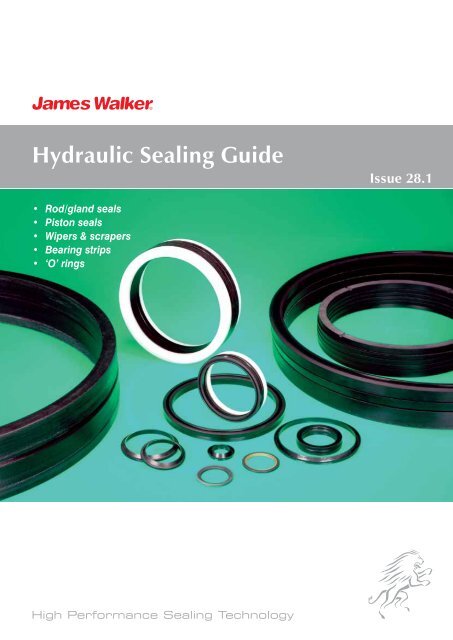
<strong>Hydraulic</strong> <strong>Sealing</strong> <strong>Guide</strong><br />
Issue 28.1<br />
• Rod/gland seals<br />
• Piston seals<br />
• Wipers & scrapers<br />
• Bearing strips<br />
• ‘O’ rings<br />
High Performance <strong>Sealing</strong> Technology
Appendix Introduction A<br />
<strong>Hydraulic</strong> sealing products<br />
James Walker’s family of hydraulic<br />
sealing products is all embracing.<br />
We provide well proven products that<br />
are designed for applications ranging<br />
from delicate instruments and control<br />
actuators right up to the heaviest<br />
forging and extrusion presses.<br />
Each product has been specifically<br />
developed to give you:<br />
• Optimum equipment performance.<br />
• Reduced leakage.<br />
• Low-friction operation.<br />
• Long trouble-free working life.<br />
Complete family<br />
We use the term hydraulic sealing<br />
products to describe the wide variety of<br />
devices used to assist and perform the<br />
sealing function in all types of hydraulic<br />
and associated equipment that help to<br />
provide dynamic reciprocating, oscillating<br />
or very slow rotational motion.<br />
Nowadays, hydraulic cylinders, and<br />
their associated control component<br />
assemblies, appear in numerous forms<br />
and sizes depending on the duties they<br />
must perform. Whatever your application,<br />
there will be a fundamental requirement<br />
for our:<br />
Rod/gland seals — to seal around the<br />
reciprocating rod or ram.<br />
Piston seals — to seal between the<br />
reciprocating piston and cylinder bore.<br />
Wipers, scrapers or protector bellows<br />
— where the ingress of external<br />
contaminants such as dust, dirt or water<br />
must be eliminated.<br />
Bearing strips — to provide support to<br />
the piston or ram under lateral loads.<br />
Family support<br />
We provide all these hydraulic sealing<br />
products, and back them with:<br />
• Top level technical support worldwide<br />
by local hydraulics sealing experts —<br />
backed by industry specialists and the<br />
leading-edge skills and knowledge of<br />
James Walker Technology Centre.<br />
• A vast range of standard sizes for all<br />
our hydraulic sealing products. This<br />
document contains general information<br />
on sizes. For the full size ranges please<br />
refer to our sister publication <strong>Hydraulic</strong><br />
sealing products — Size charts, which<br />
can be downloaded in pdf format from<br />
www.jameswalker.biz.<br />
• Standard materials suitable for the<br />
majority of applications, plus special<br />
materials for specific duties.<br />
• Ex-stock or short lead-time availability<br />
for products to national and<br />
international standards.<br />
• Express manufacture of specials, to<br />
help get your hydraulic plant back<br />
into operation with the minimum of<br />
downtime.<br />
How to use this guide<br />
Page 5: We suggest you initially turn to<br />
this page for our <strong>Hydraulic</strong> seal selection<br />
guide. This will lead you through the<br />
parameters that should be considered.<br />
Pages 6-9: Then go to our Quick<br />
reference chart. This presents an overview<br />
of our hydraulic products and gives a brief<br />
description of each, plus a page reference<br />
for detailed information on your selected<br />
items. A convenient fold-out version of this<br />
chart is attached to the rear cover.<br />
Rod/gland seals: pages 10-28 ●<br />
Piston seals: pages 10-19 & 29-34 ●<br />
Special duty products: pages 35-39 ●<br />
Wipers & scrapers: pages 40-44 ●<br />
Bearing strips: pages 45-46 ●<br />
Ram protectors: page 47 ●<br />
‘O’ rings: page 48 ●<br />
Chemical compatibility: pages 50-51<br />
Machining information: pages 52-53<br />
Appendices:<br />
Preferred housing designs: pages 54-76 ●<br />
Housing standards: pages 77-82 ●<br />
Technical guides: page 83<br />
Quick reference fold-out: page 84<br />
Alphabetical index: page 85<br />
General information: page 85<br />
James Walker contacts worldwide:<br />
page 86.<br />
2<br />
To order or for further details, call your local contact shown on rear cover or listed at www.jameswalker.biz
About James Walker<br />
Worldwide network & supply<br />
Customer support<br />
Quality — the prime factor<br />
James Walker is a dynamic global<br />
manufacturing organisation that supplies<br />
a vast range of specialised products and<br />
services to virtually every industrial sector.<br />
Our development work in fluid sealing<br />
technology started in the 1880s, swiftly<br />
followed by our products and materials<br />
achieving worldwide recognition.<br />
Today, a close-knit network of James<br />
Walker companies and official distributors<br />
covers over 100 countries. This is<br />
supported by a secure web-based and<br />
highly developed logistics operation to<br />
give you surety of supply for your:<br />
• Just-in-time (JIT) regimes.<br />
• Normal maintenance schedules.<br />
• Emergency breakdowns.<br />
We stock many thousands of different<br />
sealing products ready for same day<br />
despatch.<br />
If we do not stock the seals you need,<br />
we can supply them within days — rather<br />
than weeks. This we achieve because we<br />
compound our elastomers in-house and<br />
operate flexible manufacturing systems<br />
at our production plants, working within a<br />
tightly controlled ‘lean’ environment.<br />
When necessary, production time-scales<br />
can be reduced to just hours to help you<br />
get your plant back into operation.<br />
Our role is to provide you with the<br />
very best:<br />
• Customer support.<br />
• Technical support.<br />
• <strong>Hydraulic</strong> sealing products.<br />
• Delivery.<br />
• After sales service.<br />
James Walker’s Customer Support Centre<br />
leads the fluid sealing industry with its<br />
service to tens of thousands of customers<br />
worldwide.<br />
At a local level, on-site technical advice<br />
comes from our teams of sealing experts,<br />
backed by highly skilled applications<br />
engineers and industry specialists, plus<br />
the top-level research and development<br />
capabilities of the James Walker<br />
Technology Centre.<br />
Together, they have the knowledge and<br />
facilities to solve any fluid sealing problem<br />
for our customers.<br />
The process we select to produce your<br />
hydraulic sealing components is ruled by<br />
customer satisfaction rather than our own<br />
ease of manufacture.<br />
We select the best raw materials for each<br />
product and use advanced manufacturing<br />
techniques with strict quality control at<br />
every stage.<br />
This culminates in an exacting inspection<br />
procedure for the finished product, using<br />
state-of-the-art techniques in addition to<br />
traditional methods undertaken by skilled<br />
personnel.<br />
James Walker’s stockholding and<br />
logistics operations meet similar exacting<br />
quality standards.<br />
Our quality systems are third-party<br />
registered to BS EN ISO 9001 and<br />
BS EN 9100. We are also regularly<br />
assessed and quality approved by a wide<br />
range of industry bodies and individual<br />
customers, including multinational<br />
corporations, utilities and government<br />
organisations.<br />
To order or for further details, call your local contact 3shown on rear cover or listed at www.jameswalker.biz 3
About James Walker<br />
Production facilities<br />
Our manufacturing plants for elastomeric<br />
seals are located in the UK, USA and<br />
Australia. These, together with other<br />
production facilities around the world,<br />
ensure we provide industries at all levels<br />
with top quality engineered solutions for<br />
their sealing problems.<br />
Our in-house facilities include:<br />
• Injection moulding to 500mm<br />
(19.7 inch) diameter.<br />
• Compression moulding to 2.2m (87 inch)<br />
diameter in a single operation with one<br />
of the biggest presses for precision<br />
moulding in Europe.<br />
• Vacuum moulding to 2.1m (83 inch)<br />
diameter in a single operation.<br />
• Special production techniques that<br />
enable the manufacture of seals to<br />
unlimited diameter.<br />
• Transfer moulding.<br />
• CAD/CAM design and auto-machining<br />
of mould tools.<br />
• Rubber-to-metal bonding, with<br />
degreasing, acid etching and<br />
phosphating of metal surfaces.<br />
• CNC centre for machining engineering<br />
plastics and elastomers.<br />
• Elastomer impregnation of fabrics and<br />
fibres for production of specialised<br />
composite materials.<br />
• Batch compounding of over 300<br />
elastomer grades — with interlocked<br />
energy, time and temperature control for<br />
QA traceability.<br />
Research & development<br />
Scientists and development engineers<br />
at the James Walker Technology Centre<br />
work constantly at the leading edge of<br />
fluid sealing knowledge and materials<br />
science.<br />
They deliver the new materials, products<br />
and manufacturing techniques that<br />
improve the sealing of today’s industrial<br />
plant and meet tomorrow’s sealing<br />
demands before they arise.<br />
Custom design and manufacture is a<br />
James Walker speciality. If a standard<br />
product will not solve your problem, we<br />
have the in-house facilities to innovate,<br />
design, prototype, develop and test<br />
hydraulic sealing systems specifically to<br />
match your operational parameters.<br />
We also work on joint venture research<br />
projects with other organisations in the<br />
European <strong>Sealing</strong> Association — of which<br />
we are a founder member — and sponsor<br />
high-level research in partnership with<br />
world leading users of sealing technology.<br />
In addition to our in-house test<br />
laboratories that verify the integrity of<br />
our materials and seal designs, we<br />
regularly commission independent<br />
test houses across the world for thirdparty<br />
certification of our products to<br />
international and industry standards.<br />
4<br />
To order or for further details, call your local contact shown on rear cover or listed at www.jameswalker.biz
<strong>Hydraulic</strong> seal selection guide<br />
Piston Rod Cylinder Gland Wiper<br />
Piston Seal Bearing Strips Rod Seal<br />
Six simple steps<br />
to seal selection<br />
To select the correct hydraulic seal for<br />
your application, please consider the<br />
following steps.<br />
Step 1: Seal function<br />
The seal you require will usually be for the<br />
rod, ram, gland or piston — and you may<br />
also require wipers or bearing strips.<br />
Please look first at our Quick reference<br />
chart (pages 6-9). Select the most<br />
appropriate seals and then go to the<br />
pages quoted for full descriptions and<br />
size availabilities. A convenient fold-out<br />
version of this chart is attached to the<br />
rear cover.<br />
Step 2: <strong>Sealing</strong> method<br />
Depending on your application, you may<br />
require single, double or multi-lip sealing.<br />
Fine tune your selection of possible seals<br />
by considering the method of sealing<br />
required. For example, it could be the<br />
single action of our Solosele ® G, the<br />
double action of Lionsele ® P, or the multilip<br />
sealing action of a Chevron ® set.<br />
Note that single-acting seals (eg, Solosele G)<br />
may be used in a back-to-back<br />
arrangement in separate housings on<br />
double-acting piston assemblies.<br />
Step 3: Operational parameters<br />
The maximum pressure of the application<br />
should be considered along with the<br />
temperature range in which it will operate.<br />
Reciprocating speed also needs to be<br />
considered: the standard maximum<br />
cylinder stroke speed is 0.5m/s, with<br />
some of our seals rated higher. If your<br />
application requires higher speeds than<br />
the seal you have selected, then please<br />
consult our Technical Support Team.<br />
Stroke length should also be considered<br />
when calculating the seal depth:<br />
stroke length divided by 2.5 is the<br />
maximum recommended seal depth —<br />
otherwise fluid film lubrication may be<br />
compromised.<br />
Step 4: Material compatibility<br />
To determine that the seal materials are<br />
compatible with your system media,<br />
please check the Materials of construction<br />
and Media capabilities as stated in the<br />
seal’s full description.<br />
You can also cross-reference the materials<br />
and media on our Chemical compatibility<br />
chart on pages 50-51. If in doubt please<br />
consult our Technical Support Team.<br />
Step 5: Operational features<br />
Please consider and check availability of<br />
your seal for the following:<br />
Endless: this is our preferred method of<br />
supply, as it provides the highest sealing<br />
integrity.<br />
Split-type: for easier and quicker<br />
installation during plant maintenance.<br />
Step 6: Sizing the seal<br />
Refer to the section drawings for the<br />
required housing measurements, then<br />
check the standard listings charts for the<br />
JW Order Code in our sister publication<br />
<strong>Hydraulic</strong> sealing products — Size charts<br />
(this can be downloaded in pdf format<br />
from www.jameswalker.biz).<br />
If the size you require does not appear,<br />
please consult our Customer Support<br />
Centre or your local James Walker<br />
company for a quotation.<br />
Note: Prior to sizing your seals, please<br />
check the condition of the rod, gland,<br />
housing, etc. Ensure all plant components<br />
meet manufacturer’s recommendations,<br />
such as surface finish.<br />
For more information, please refer to<br />
Machining information (pages 52-53) and<br />
Housing details (pages 54-82).<br />
To order or for further details, call your local contact 5shown on rear cover or listed at www.jameswalker.biz 5
JAMES WALKER S.P.S. Ltd.<br />
Marcoms Department<br />
Leaflet :<br />
<strong>Hydraulic</strong> <strong>Sealing</strong> Products<br />
Pages 6 a<br />
Appendix Quick reference A chart<br />
Overview of products<br />
Rod/gland seals<br />
Chevron ®<br />
Lion ® Expanding Packing<br />
Lionsele ® G<br />
Lionsele ® LF<br />
Lionsele ® U1<br />
Lionsele ® U2<br />
Lofilm ®<br />
Lofilm ® HD<br />
Solosele ® G<br />
Twinset<br />
U-rings<br />
JAMES WALKER S.P.S. Ltd.<br />
Marcoms Department<br />
Piston seals<br />
Chevron ®<br />
Lionsele ® LF<br />
Lionsele ® P<br />
Lionsele ® SP<br />
Lionsele ® U1<br />
Lionsele ® U3<br />
Solosele ® G<br />
Solosele ® S<br />
Solosele ® SW<br />
Twinset<br />
U-rings<br />
Fabric gland ring<br />
and rubber header<br />
Key to materials<br />
Elastomers<br />
Polyurethanes<br />
Thermoplastics<br />
Rubber-proofed fabric<br />
PTFE — virgin & filled<br />
Leaflet : Decades of duty on Date older : plant<br />
Leaflet : Sketch reference :<br />
Resin-proofed JAMES <strong>Hydraulic</strong> fabric WALKER <strong>Sealing</strong> Products S.P.S. Max Ltd. operating pressure: 12/11/2010 <strong>Hydraulic</strong> 34MPa <strong>Sealing</strong> Products Chevron sets<br />
Marcoms DepartmentMax surface speed: 0.5m/s Pages 6 and 88 - Lion<br />
Metals<br />
Pages 6 and Max 84 temperature: - Chevron +100°C sets<br />
Supplied: Endless<br />
Plastic gland ring<br />
Chevron and rubber ®<br />
header<br />
Rod/gland seal<br />
Piston seal<br />
Twinset<br />
Rod/gland seal<br />
Piston seal<br />
Details: P14-15 + Appendix C<br />
S/A gland ring (Piston)<br />
Lionsele and Lionsele plastic ® LF header LF<br />
Rod/gland seal<br />
Piston seal<br />
Twinset<br />
Special duty<br />
Composite seals<br />
Self-aligning Gland Rings<br />
Solosele ® KB Hydro<br />
Tube test seals<br />
Fabric gland ring<br />
and plastic header<br />
Wipers<br />
Lionsele ® W1<br />
Lionsele ® W2<br />
Lionsele ® W3<br />
Wiper Type L<br />
Wyclip ®<br />
Universally proven multi-lip packing Very low friction: smoothest operation<br />
Max operating pressure: 42MPa<br />
Max operating pressure: 40MPa<br />
Leaflet :<br />
Max surface speed: JAMES 0.5m/sWALKER S.P.S. Maximum Ltd. surface speed: <strong>Hydraulic</strong> Leaflet 5.0m/s <strong>Sealing</strong> : Products<br />
<strong>Hydraulic</strong> <strong>Sealing</strong> Products<br />
Temperature Plastic range: gland Marcoms -20°C ring to +100/120°C Department Temperature S/A gland range: ring -250°C (Rod) to Pages +260°C 6 and 88 - Lions<br />
Supplied: Marcoms Split & endless Department Supplied: Endless Pages 6 and 88 - So<br />
and plastic header<br />
and plastic header<br />
Details: P10-11 + Appendix A<br />
Details: P16-17 + Appendix D<br />
JAMES WALKER S.P.S. Ltd.<br />
Solosele Standard ® G rubber<br />
and fabric<br />
Rod/gland seal<br />
Piston seal<br />
Rubber Lionsele / ® fabric U1 with<br />
plastic Lionsele A/E (Piston) U1<br />
Rod/gland seal<br />
Piston seal<br />
Rubbe<br />
plast<br />
Bearing strips<br />
Lionsele ® B1<br />
Lionsele ® B2<br />
Ram protectors<br />
Comflex ® Bellows<br />
‘O’ rings<br />
Virtually all standards & sizes<br />
Note: Statements of operating limits<br />
quoted are not an indication that these<br />
values can be applied simultaneously.<br />
Robust single element seal<br />
Max operating pressure: 42MPa<br />
Max surface speed: 0.5m/s<br />
Temperature range: -20°C to +120°C<br />
Supplied: Endless<br />
Details: P12-13 + Appendix B<br />
Rubber with<br />
plastic A/E (Piston)<br />
Ideal for aggressive environments<br />
Max operating pressure: 42MPa<br />
Maximum surface speed: 0.5m/s<br />
Temperature range: -30°C to +100°C<br />
Supplied: Endless<br />
Details: P18 + Appendix E<br />
Rubber with<br />
plastic A/E (Rod)<br />
6<br />
To order or for further details, call your local contact shown on rear cover or listed at www.jameswalker.biz
JAMES WALKER S.P.S. Ltd.<br />
Marcoms Department<br />
Leaflet :<br />
<strong>Hydraulic</strong> <strong>Sealing</strong> Products<br />
Pages 7 and 84<br />
Quick reference chart<br />
JAMES WALKER S.P.S. Ltd.<br />
Marcoms Department<br />
U-rings<br />
U Rings<br />
Rod/gland seals<br />
Piston seals<br />
Leaflet :<br />
Date :<br />
<strong>Hydraulic</strong> <strong>Sealing</strong> Products<br />
14/07/2010<br />
Pages 7 and 88 - U Rings<br />
Sketch reference :<br />
U Rings<br />
JAMES WALKER S.P.S. Ltd.<br />
Leaflet :<br />
<strong>Hydraulic</strong> <strong>Sealing</strong> Products<br />
Fabric gland ring<br />
Marcoms Department<br />
Lionsele SP<br />
Plastic gland ring S<br />
Lofilm ® HD<br />
Lionsele ® SP<br />
Rod/gland seal<br />
Piston seal Lionsele SP<br />
Date :<br />
14/03/2010<br />
Sketch reference :<br />
Lionsele SP -001<br />
Leaflet :<br />
Date<br />
For<br />
:<br />
forging<br />
Sketch<br />
& extrusion<br />
reference<br />
presses<br />
:<br />
Double-acting, for spool-type pistons<br />
<strong>Hydraulic</strong> <strong>Sealing</strong> Products<br />
Leaflet :<br />
12/11/2010 Lofilm<br />
Operating capabilities: Depend on Max operating JAMES<br />
sets<br />
pressure: WALKER 62MPa S.P.S. Ltd. Max operating pressure: <strong>Hydraulic</strong> 42MPa<br />
<strong>Sealing</strong> Products 14<br />
design and materials Pages 7 of and construction. 84 - Lofilm sets Max surface speed: Marcoms 0.5m/s DepartmentMaximum surface speed: 0.5m/s Pages 7 and 88 - Lionse<br />
Supplied in a variety of elastomers<br />
and rubberised fabrics.<br />
Temperature range: -20°C to +120°C<br />
Supplied: Split & endless<br />
Temperature range: -20°C to +100°C<br />
Supplied: Endless<br />
Details: P19<br />
Plastic gland ring<br />
Lofilm ®<br />
Rod/gland seal<br />
Details: P24-25 + Appendix H<br />
Lionsele ® G<br />
Rod/gland seal<br />
Details: P29 + Appendix J<br />
Lionsele P<br />
Lionsele ® P<br />
Piston seal<br />
Highly versatile multi-lip seal<br />
High performance, single-acting<br />
Leaflet :<br />
Date : Sketch reference :<br />
S.P.S. Max Ltd. operating pressure: <strong>Hydraulic</strong> 42MPa <strong>Sealing</strong> Products Max 12/11/2010 operating Lion pressure: Expanding 40MPa<br />
rtment Max surface speed: 0.5m/s Pages 7 and 84 - Lion Expanding Max surface Packingspeed: 5.0m/s<br />
Temperature range: -20°C to +120°C Temperature range: -25°C to +120°C<br />
Supplied: Split & endless<br />
Supplied: Endless Leaflet :<br />
S/A gland ring (Piston)<br />
Details: P20-21 + Appendix F<br />
Lion Expanding Packing<br />
Lion ® Expanding Packing<br />
Rod/gland seal<br />
JAMES WALKER S.P.S. Ltd.<br />
Marcoms Department<br />
Details: P26-27 + Appendix I<br />
Lionsele Lionsele ® U2 U2<br />
Rod/gland seal<br />
JAMES WALKER S.P.S. Ltd.<br />
Marcoms Department<br />
Date :<br />
<strong>Hydraulic</strong> <strong>Sealing</strong> Products<br />
17/02/2010<br />
Lionsele U2<br />
Sketch reference :<br />
Lionsele U2 001<br />
High performance, double-acting seal<br />
Max operating pressure: 40MPa Pages 7 and 88 - So<br />
Max surface speed: 5.0m/s<br />
Temperature range: -25°C to +120°C<br />
Supplied: Endless<br />
Details: P30-31 + Appendix K<br />
Solosele S<br />
Solosele ® S<br />
Piston seal<br />
Leaflet :<br />
<strong>Hydraulic</strong> <strong>Sealing</strong> Products<br />
Robust multi-lip packing<br />
Max operating pressure: 62MPa<br />
Max surface speed: 0.5m/s<br />
Temperature range: -20°C to +100°C<br />
Supplied: Split & endless<br />
Details: P22-23 + Appendix G<br />
Single-acting seal in polyurethane<br />
Max operating pressure: 42MPa<br />
Maximum surface speed: 0.5m/s<br />
Temperature range: -30°C to +100°C<br />
Supplied: Endless<br />
Details: P28 + Appendix E<br />
For split-type piston heads<br />
Max operating pressure: 42MPa<br />
Max surface speed: 0.5m/s<br />
Temperature range: -20°C to +120°C<br />
Supplied: Endless<br />
Details: P32 + Appendix L<br />
To order or for further details, call your local contact 7shown on rear cover or listed at www.jameswalker.biz 7
S.P.S. Ltd.<br />
artment<br />
Quick reference chart<br />
JAMES WALKER S.P.S. Ltd.<br />
Leaflet :<br />
Date :<br />
<strong>Hydraulic</strong> <strong>Sealing</strong> Products<br />
14/07/2010<br />
Marcoms<br />
Pages 8 and<br />
Department<br />
88 - Solosele SW<br />
JAMES WALKER S.P.S. Ltd.<br />
Marcoms Department<br />
Leaflet :<br />
Date :<br />
Sketch reference :<br />
<strong>Hydraulic</strong> <strong>Sealing</strong> Products<br />
14/07/2010<br />
Solosele SW<br />
Pages 8 nd 88 - Solosele KB Hydro<br />
Leaflet :<br />
<strong>Hydraulic</strong> <strong>Sealing</strong> Products<br />
Pages 8 and 88<br />
Solosele Solosele ® SW SW<br />
Piston seal<br />
Solosele Solosele ® KB KB Hydro<br />
Special duty seals<br />
Lionsele W1<br />
Lionsele ® W1<br />
Wiper<br />
Robust double-acting seal<br />
Blade root seal for Kaplan turbines Medium duty wiper for <strong>Hydraulic</strong> sand <strong>Sealing</strong> & mud Products<br />
Max operating pressure: Leaflet 42MPa :<br />
Cost Date effective, : Sketch Marcoms long-term reference : sealing on slow Temperature range: -30°C to +100°C<br />
.P.S. Ltd.<br />
Leaflet<br />
Department<br />
:<br />
Pages 8 and 88 -<br />
<strong>Hydraulic</strong> <strong>Sealing</strong> Products<br />
Date : Sketch reference :<br />
14/07/2010 Lionsele U3<br />
Max surface speed: JAMES 0.5m/s WALKER S.P.S. Ltd. oscillating duties associated <strong>Hydraulic</strong> <strong>Sealing</strong> with Products Kaplan Supplied: 25/10/2010Endless<br />
F1 ; HSG28 - P15<br />
tmentTemperature range: -20°C to Pages +100°C 8 and 88 - Lionsele water U3<br />
Marcoms Department turbines.<br />
Pages 8 and 84 - Tube High test performance seals polyurethane wiper<br />
Supplied: Endless<br />
Details: P33 + Appendix M<br />
Supplied: Endless & OSJ ®<br />
(On-Site Joining)<br />
Details:<br />
Insert<br />
P36-37<br />
on Pages 8 and 84<br />
with excellent wear resistance.<br />
Details: P40 + Appendix O<br />
Lionsele<br />
Lionsele ®<br />
U3<br />
U3<br />
Piston seal<br />
JAMES WALKER S.P.S. Ltd.<br />
Tube test seals<br />
Tube test seals<br />
Special duty seals<br />
Lionsele ® W2<br />
Wiper<br />
Lionsele W2<br />
Leaflet :<br />
P.S. Ltd.<br />
ment<br />
Reduces risk of inter-seal Leaflet pressure :<br />
Date :<br />
Medium-to-heavy duty wiper Leaflet :<br />
<strong>Hydraulic</strong> <strong>Sealing</strong> Products<br />
20/08/2010<br />
Max operating pressure: 42MPa<br />
For hydrostatic JAMES testingWALKER S.P.S. Ltd. Temperature range:<br />
<strong>Hydraulic</strong><br />
-30°C<br />
<strong>Sealing</strong><br />
to +100°C<br />
Products<br />
Maximum surface speed: 0.5m/s Pages 8 and 88 - Composite Maximum Seal operating Marcoms pressures: DepartmentSupplied: Endless<br />
Pages 8 and 88 - Lions<br />
Temperature range: -30°C to +100°C<br />
Polyurethane versions: 100MPa<br />
Metal-cased polyurethane wiper. Selfretaining<br />
Date : design for open-faced housings.<br />
Supplied: Endless<br />
Rubberised fabric versions: Leaflet : 69MPa<br />
JAMES WALKER S.P.S. Supplied: Ltd.<br />
<strong>Hydraulic</strong> <strong>Sealing</strong> Products<br />
20/08/2010<br />
Endless<br />
Details: P34 + Appendix Marcoms E Department<br />
Details: P41 + Appendix P<br />
Used on tube testing machines Pages that 8 and seal 88 - SA Gland Ring<br />
and release repeatedly.<br />
Composite Seal<br />
Composite seals<br />
Special duty seals<br />
Details: P38<br />
SA Gland Ring<br />
Self-aligning Gland Rings<br />
Special duty — optional feature<br />
Lionsele W3<br />
Lionsele ® W3<br />
Wiper<br />
Custom-designed & manufactured<br />
Combine compactness with low break-out<br />
and dynamic friction for instant response<br />
on customer-specific hydraulic and<br />
pneumatic control systems.<br />
Supplied: Endless<br />
Details: P35 + Appendix N<br />
Recommended for arduous conditions<br />
For Chevron ® , Lion ® Expanding Packing,<br />
Lofilm ® and Lofilm ® HD seals when used<br />
with heavily worn rams, shafts with large<br />
offset, and systems with extrusion gaps.<br />
Details: P39<br />
Double-acting wiper<br />
Temperature range: -30°C to +100°C<br />
Supplied: Endless<br />
Polyurethane wiper with chamfered lips<br />
designed to prevent dirt ingress and<br />
control fluid film build up.<br />
Details: P42 + Appendix Q<br />
8<br />
To order or for further details, call your local contact shown on rear cover or listed at www.jameswalker.biz
.P.S. Ltd.<br />
tment<br />
Leaflet :<br />
<strong>Hydraulic</strong> <strong>Sealing</strong> Products<br />
JAMES WALKER S.P.S. Ltd.<br />
Marcoms Department<br />
Pages 9 and 88 - Wyclip<br />
Date :<br />
20/08/2010<br />
Leaflet :<br />
<strong>Hydraulic</strong> <strong>Sealing</strong> Products<br />
Quick reference chart<br />
Date :<br />
20/08/2010<br />
Pages 9 and 88 - Lionsele B2<br />
Wyclip ®<br />
Scraper/wiper<br />
Wyclip<br />
Lionsele Lionsele ® B2 B2<br />
Bearing strip<br />
‘O’ rings<br />
Highly versatile seals<br />
Heavy duty scraper/wiper<br />
Temperature range: -40°C to +100°C<br />
Supplied: Endless<br />
A simple design of clip-in wiper that is<br />
widely used on hydraulic actuators.<br />
Details: P43 + Appendix R<br />
Wiper Type L<br />
Wiper<br />
Wiper for highly abrasive media<br />
Temperature range: -35°C to +120°C<br />
Supplied: Split & endless<br />
Robust and wear-resistant wiper of tough<br />
Leaflet :<br />
S.P.S. rubberised Ltd. fabric construction.<br />
<strong>Hydraulic</strong> <strong>Sealing</strong> Products<br />
artment<br />
Details: P44 + Appendix S<br />
For heavy duty applications<br />
Max bearing stress (static; RT): 400MPa<br />
Max bearing stress (dynamic; Leaflet RT): : 90MPa<br />
Date :<br />
JAMES WALKER S.P.S. Ltd.<br />
<strong>Hydraulic</strong> <strong>Sealing</strong> Products<br />
20/08/2010<br />
Max relative speed: 1.0m/s.<br />
Marcoms Department Temperature range: -60°C<br />
Pages<br />
to +100°C<br />
9 and 88 - Comflex Fabric Bellows<br />
Supplied: Strip form or machined bearing.<br />
Wiper Type 'L'<br />
JAMES WALKER S.P.S. Ltd.<br />
Marcoms Department<br />
Details: P46 + Appendix T<br />
Comflex Fabric Bellows<br />
Comflex ® Bellows<br />
Ram protectors<br />
Leaflet :<br />
<strong>Hydraulic</strong> <strong>Sealing</strong> Products<br />
Robust, heavy-duty protection<br />
Fabric-reinforced elastomeric bellows of<br />
fully vulcanised construction. Protect rams<br />
Wiper Type 'L'<br />
Date :<br />
Pages 9 and 88 - Lionsele B1<br />
working 20/08/2010 in aggressive environments on<br />
forging presses, pulverising mills, etc.<br />
Date :<br />
2/03/2010<br />
Details: P47<br />
Many thousands of types and sizes<br />
BS ISO 3601-1 (metric & inch).<br />
BS 1806 (inch: now superseded by<br />
BS ISO 3601-1 Class A).<br />
SAE AS 586 (inch).<br />
BS 4518 (metric).<br />
Stocked material grades include:<br />
Nitrile rubber (NBR).<br />
Elast-O-Lion ® hydrogenated nitrile<br />
(HNBR) including RGD resistant.<br />
Ethylene-propylene (EPM).<br />
Silicone rubber (VMQ).<br />
Fluoroelastomer (FKM), including<br />
RGD resistant.<br />
Details: P48<br />
Lionsele Lionsele ® B1 B1<br />
Bearing strip<br />
Sketch reference :<br />
Type L -004<br />
Bronze-loaded PTFE for low friction<br />
Max bearing stress (static; RT): 25MPa<br />
Max bearing stress (dynamic; RT): 12MPa<br />
Max relative speed: 5.0m/s<br />
Temperature range: -60°C to +150°C<br />
Supplied: Strip form or machined bearing.<br />
Details: P45 + Appendix T<br />
To order or for further details, call your local contact 9shown on rear cover or listed at www.jameswalker.biz 9
Header Chevron ® for rods/glands & pistons<br />
Rod / gland seals<br />
Piston seals<br />
Chevron ®<br />
Universally proven multi-lip packing<br />
Description<br />
Chevron ® (known as Shallex ® in some<br />
regions) is our universal multi-lip<br />
packing set that is highly regarded<br />
for its long working life and ability to<br />
operate under adverse mechanical<br />
conditions. When used in split form it<br />
can provide major downtime savings.<br />
This robust packing set comprises a<br />
gland ring/female adapter, header/male<br />
adapter, and one or more intermediate<br />
V-shaped rings. The rings are tapered<br />
to give an initial interference fit when<br />
confined in the seal housing. The resulting<br />
radial force together with the fine finish of<br />
the lip, ensure a good seal at low or slack<br />
pressures. A scarf abutment is used when<br />
the seal is needed in split form.<br />
Special features<br />
• Double-acting capabilities when fitted<br />
back-to-back.<br />
• Recommended for safety critical duties<br />
and adverse mechanical conditions.<br />
• Excellent extrusion and wear resistance.<br />
• Options available to suit adjustable and<br />
non-adjustable axial housing lengths.<br />
• Available with Self-aligning Gland<br />
Ring (see page 39).<br />
Typical applications<br />
Standard materials: most types of<br />
hydraulic press (main rams and drawback<br />
rams); hydraulic cylinder glands and<br />
piston heads; hydraulic valves; oil pipeline<br />
expansion glands.<br />
Special materials: reciprocating steam,<br />
water, boiler feed and oil pumps; hot oil<br />
reciprocating pumps for refinery duties up<br />
to +260°C; sludge pumps and swivels.<br />
Operating capabilities<br />
• Maximum operating pressure:<br />
42MPa (6092psi). Modified design/<br />
materials can considerably extend this.<br />
• Temperature range (standard<br />
materials): -20°C to +100°C (-4°F to<br />
+212°F) for up to 250mm (9.84 in) OD,<br />
or to +120°C (+248°F) above 250mm<br />
(9.84 in) OD.<br />
• Maximum temperature (special<br />
materials): up to +260°C (+500°F).<br />
• Maximum surface speed: 0.5m/s<br />
(98.4fpm). For higher speeds please<br />
consult our Technical Support Team.<br />
Materials of construction<br />
Size range Set ring Standard materials Special materials<br />
Up to & including<br />
250mm OD<br />
(9.84 in)<br />
Above<br />
250mm OD<br />
(9.84 in)<br />
Gland (female<br />
adapter)<br />
V-shaped<br />
intermediate<br />
*Header<br />
(male adapter)<br />
Gland (female<br />
adapter)<br />
V-shaped<br />
intermediate<br />
*Header<br />
(male adapter)<br />
High performance acetal<br />
copolymer<br />
Cotton fabric proofed with a<br />
blend of synthetic rubbers<br />
High performance acetal<br />
copolymer<br />
Cotton fabric proofed with a<br />
blend of synthetic rubbers<br />
Cotton fabric proofed with a<br />
blend of synthetic rubbers<br />
Solid hard rubber, or cotton<br />
fabric proofed with a blend<br />
of synthetic rubbers<br />
A range of solid rubbers.<br />
Fabric proofed with<br />
hydrogenated nitrile<br />
(HNBR) or fluorocarbon<br />
(FKM) and others.<br />
Acetal, PEEK TM , PTFE<br />
UHMWPE, nylon, etc.<br />
A range of metals.<br />
* Non-standard — spring-loaded headers<br />
Header rings produced from thermoplastics or metals in radial sections of 6.5mm (0.256 in) and<br />
above can be supplied with multiple open-coil springs to give a degree of compensation for wear<br />
and loss of interference of sealing rings.<br />
10<br />
To order or for further details, call your local contact shown on rear cover or listed at www.jameswalker.biz
Chevron ® ffor rrods/glands & Header pistons<br />
Media capabilities<br />
Standard materials are suitable for use<br />
with most mineral-based hydraulic fluids,<br />
and most fire-resistant fluids of the water/<br />
oil or water/glycol types at up to 100°C<br />
(212°F). Also resistant to air, water and<br />
most lubricating oils and greases.<br />
Where fire-resistant fluids are used, it is<br />
essential to advise our Technical Support<br />
Team of the type and designation due to<br />
the effects that can occur with different<br />
grades.<br />
Special materials considerably extend<br />
the range of application in terms of<br />
temperature, fluid compatibility and<br />
abrasion resistance. Ask our Technical<br />
Support Team for further information.<br />
How supplied<br />
(Also see <strong>Hydraulic</strong> sealing products —<br />
Size charts, which can be downloaded<br />
from www.jameswalker.biz)<br />
Available in radial sections from 4mm<br />
(0.16 in) upwards; spring-loaded versions<br />
from 6.5mm (0.26 in). Endless rings<br />
available up to 2.2m (87 in) OD.<br />
Endless packing sets in standard<br />
materials to suit housings to BS ISO 5597<br />
— Long (L3) axial length series are readily<br />
available. Inch sizes and split packing sets<br />
are also available.<br />
Fitting instructions are supplied with every<br />
packing set.<br />
Chevron ® typical housings<br />
See Appendix A (page 54) for preferred housing designs, and Appendix W<br />
(pages 79-82) for BS ISO 5597 — Long (L3) axial length series housings.<br />
Direction<br />
of<br />
pressure<br />
Bi-Directional<br />
pressure<br />
Direction<br />
of<br />
pressure<br />
Bearing housing<br />
Bearing<br />
housings<br />
Bearing housing<br />
Wiper housing<br />
Chevron ®<br />
single-acting<br />
piston application<br />
Chevron ®<br />
double-acting<br />
piston application<br />
Chevron ® rod<br />
application<br />
Rod / gland seals Piston seals<br />
To order or for further details, call your local contact 11 shown on rear cover or listed at www.jameswalker.biz 11
Header Solosele ® G seal for rods/glands & pistons<br />
Rod / gland seals<br />
Solosele ® G<br />
Robust single element seal<br />
Description<br />
Solosele ® G is our compact rod/gland<br />
seal and single-acting piston seal that<br />
saves space without compromising its<br />
high integrity sealing capabilities.<br />
Standard versions comprise a profiled<br />
elastomeric sealing element that is firmly<br />
protected by an integral anti-extrusion<br />
element of rubber-proofed fabric. High<br />
integrity sealing is enhanced by its flexible<br />
chamfered lips.<br />
Piston seals<br />
In operation, the elastomeric element<br />
provides low-pressure sealing by means<br />
of radial squeeze. As pressure increases,<br />
its pressure responsive action maintains<br />
the sealing force — even when there is<br />
significant rod misalignment.<br />
The tough integral fabric/rubber base<br />
resists extrusion whilst being sufficiently<br />
flexible to allow recess fitting in the<br />
majority of cases.<br />
Special features<br />
• Compact seal with excellent high and<br />
low pressure sealing capabilities.<br />
• Excellent extrusion resistance for long<br />
operational life.<br />
• Simple to fit.<br />
• Cost savings through simple housing<br />
groove requirements.<br />
Special versions<br />
Solosele ® G-AE is available with separate<br />
triangular base ring (internal or external)<br />
of PTFE, nylon or acetal to reduce friction<br />
or limit seal contact area on short stroke<br />
applications. Dependent on whether<br />
the seal is used in a rod/gland or piston<br />
sealing application, the seal base ID or<br />
OD corner has a moulded chamfer recess<br />
in which the split anti-extrusion (AE)<br />
element/ring is positioned.<br />
Odd-legged design is available<br />
to prevent excessive axial<br />
movement within the housing.<br />
This prevents fluid pumping<br />
under the seal lip during<br />
low-pressure rod retraction.<br />
Typical applications<br />
Rod seal for hydraulic cylinders; ram seal<br />
for hydraulic presses; or single-acting<br />
piston seal. (Two seals can be used for<br />
double-acting piston duties, but care must<br />
be taken to relieve any potential inter-seal<br />
pressure build up.)<br />
It is also suitable for slow semi-rotary<br />
applications including swivels and<br />
distributors. Additional duties include<br />
turbine blade roots, guide vanes and<br />
servo motors on hydroelectric plant —<br />
and as a static seal that offers the benefits<br />
of an ‘O’ ring with integral anti-extrusion<br />
capability.<br />
Operating capabilities<br />
• Maximum operating pressure:<br />
42MPa (6092psi).<br />
• Temperature range (standard materials):<br />
-20°C to +120°C (-4°F to +248°F).<br />
• Temperature limits (special materials):<br />
down to -45°C (-49°F) with low nitrile<br />
(NBR); or up to +200°C (+392°F) with<br />
fluoroelastomer (FKM).<br />
• Maximum surface speed<br />
(reciprocating): 0.5m/s (98.4fpm).<br />
For higher speeds please consult our<br />
Technical Support Team.<br />
Materials of construction<br />
Elastomeric sealing element<br />
Standard material: medium nitrile (NBR).<br />
Special materials: low nitrile (NBR), or<br />
fluoroelastomer (FKM).<br />
Anti-extrusion element<br />
Standard material: cotton fabric proofed<br />
with a blend of synthetic rubbers.<br />
Special materials: cotton fabric proofed<br />
with blend of synthetic rubbers for<br />
use with sealing element of low nitrile<br />
(NBR). Fabric proofed with fluorocarbon<br />
(FKM) for use with sealing element of<br />
fluorocarbon (FKM).<br />
Media capabilities<br />
Standard materials are suitable for use<br />
with most mineral based hydraulic fluids,<br />
and most fire-resistant fluids of the water/<br />
oil emulsion or water/glycol types at<br />
temperatures up to 120°C (248°F). They<br />
also resist air, water, and most lubricating<br />
oils and greases.<br />
Special materials extend considerably<br />
the range of application in terms of<br />
temperature, fluid compatibility and<br />
abrasion resistance. Please consult our<br />
Technical Support Team.<br />
12<br />
To order or for further details, call your local contact shown on rear cover or listed at www.jameswalker.biz
Solosele ® G seal for rods/glands & Header pistons<br />
How supplied<br />
(Also see <strong>Hydraulic</strong> sealing products —<br />
Size charts, which can be downloaded<br />
from www.jameswalker.biz)<br />
Standard sizes to fit piston head and rod/<br />
gland housings to BS ISO 5597 — Short<br />
(L1) and Medium (L2) axial length series,<br />
and BS ISO 6020-2 are readily available.<br />
Numerous other moulds available for nonstandard<br />
sizes from 3mm ID to 2.2m OD.<br />
Standard inch sizes from 0.125 inch ID<br />
to 87 inch OD.<br />
Other sizes within these metric and inch<br />
limits are manufactured to order, but<br />
tooling charges may be incurred.<br />
Larger diameter endless seals — to<br />
unlimited OD — can be made using our<br />
special mould-joining technique.<br />
Solosele ® G is supplied as standard<br />
in endless form for optimum sealing<br />
performance.<br />
Fitting instructions are supplied with<br />
every seal.<br />
Solosele ® G typical housings<br />
Standard ; Rubber<br />
Standard ; Rubber<br />
with integral fabric<br />
with integral fabric<br />
See with Appendix integral fabric B (page 55) for preferred housing designs and Appendix W (pages 79-82)<br />
and separate plastic with separate plastic with integral fabric and separate plastic with separate plastic<br />
only A/E element<br />
for BS ISO 5597 — A/E Short element<br />
A/E element only A/E element<br />
(L1) and Medium (L2) axial length series, A/E element<br />
A/E element<br />
and BS ISO 6020-2<br />
housings.<br />
Single-acting piston applications<br />
Direction<br />
of<br />
pressure<br />
Standard ; Rubber<br />
with integral fabric<br />
only A/E element<br />
Single component housing assembly<br />
Standard ; Rubber<br />
with integral<br />
Bearing<br />
fabric<br />
and separate housings plastic<br />
A/E element<br />
Double-acting piston applications<br />
Single component housing assembly<br />
Bearing housing groove<br />
Standard ; Rubber<br />
Standard ; Rubber with integral fabric<br />
with integral fabric and separate plastic<br />
only A/E element A/E element<br />
Shaft sealing applications<br />
Direction<br />
of<br />
pressure<br />
Single component housing assembly<br />
JAMES WALKER S.P.S. Ltd.<br />
Marcoms Department<br />
Standard ; Rubber<br />
Standard ; Rubber<br />
with separate plastic<br />
A/E element<br />
Typical Solosele ® G constructions<br />
Bi-directional<br />
pressure<br />
Standard ; Rubber<br />
with separate plastic<br />
A/E element<br />
Standard ; Rubber<br />
Direction<br />
of<br />
pressure<br />
Standard ; Rubber<br />
with integral fabric<br />
only A/E element<br />
Standard ; Rubber<br />
with integral fabric<br />
only A/E element<br />
Direction<br />
of<br />
pressure<br />
Standard ; Rubber<br />
Multi-component housing assembly<br />
Standard ; Rubber<br />
with<br />
Bearing<br />
integral fabric<br />
and housings separate plastic<br />
A/E element<br />
Standard ; Rubber<br />
Multi-component housing assembly<br />
Standard ; Rubber<br />
with separate plastic<br />
A/E element<br />
Bearing housing groove<br />
Standard ; Rubber<br />
with integral fabric Standard ; Rubber<br />
and separate plastic with separate plastic<br />
A/E element<br />
A/E element<br />
Multi-component housing assembly<br />
Leaflet :<br />
Date :<br />
Sketch reference :<br />
Bearing housing Wiper housing <strong>Hydraulic</strong> <strong>Sealing</strong> Products Bearing housing 19/01/2011 Wiper HSG28 housing - P13<br />
Rubber with integral<br />
fabric only<br />
AE element<br />
Rubber with integral<br />
fabric and separate<br />
plastic AE element<br />
Solosele G ; Types and construction<br />
Rubber with<br />
separate plastic<br />
AE element<br />
All rubber<br />
Rod / gland seals Piston seals<br />
To order or for further details, call your local contact 13<br />
shown on rear cover or listed at www.jameswalker.biz 13
Header Twinset packing for rods/glands & pistons<br />
Rod / gland seals<br />
Twinset<br />
Well proven over many decades<br />
Description<br />
Twinset is our pressure responsive<br />
packing set that boasts a record of<br />
success stretching back over 50 years.<br />
Although we recommend our more<br />
advanced designs for many of the<br />
traditional Twinset applications, this<br />
product remains a firm favourite with<br />
the operators of older hydraulic plant.<br />
Piston seals<br />
The packing set comprises an endless<br />
U-ring firmly supported by a header ring.<br />
The lips of the U-ring are slightly flared<br />
to provide an interference fit for initial<br />
sealing. When system pressure is applied,<br />
the sealing force is increased significantly<br />
by reaction within the tongue-shaped<br />
cavity of the U-ring.<br />
Under slight axial compression, the<br />
header ring also spreads the U-ring lips<br />
slightly to improve low pressure sealing<br />
efficiency.<br />
Special features<br />
• Very well proven on reciprocating plant<br />
worldwide.<br />
• Readily available in traditional sizes for<br />
older plant.<br />
• Suitable for adjustable and nonadjustable<br />
axial length housings.<br />
Typical applications<br />
Twinset was developed for use on<br />
vertically reciprocating hydraulic shafts<br />
and rams. Current applications include<br />
the main rams of upstroking/gravity return<br />
presses and downstroking/prefilling<br />
type presses. Twinset has also proved<br />
successful on press drawback rams,<br />
hydraulic piston heads, jacks and hoists,<br />
and hydraulic valves.<br />
This packing set should not be used<br />
under abrasive conditions or for heavyduty<br />
applications (eg, forging or extrusion<br />
presses), or on rams subjected to shock<br />
loads or side loads. In these cases,<br />
please ask our Technical Support Team to<br />
recommend a suitable product.<br />
Operating capabilities<br />
• Maximum operating pressure:<br />
34MPa (4931psi).<br />
• Maximum temperature (standard<br />
materials): 100°C (212°F).<br />
• Maximum surface speed: 0.5m/s<br />
(98.4fpm).<br />
Materials of construction<br />
U-ring<br />
Standard material: cotton fabric proofed<br />
with a blend of synthetic rubbers.<br />
Header ring<br />
Standard material: nylon, or a similarly<br />
hard composite.<br />
Spring-loaded: header rings of 6.5mm<br />
section and above can be supplied with<br />
multiple coil springs for the automatic<br />
compensation of wear when used in nonadjustable<br />
housings.<br />
Media compatibility<br />
Standard materials are suitable for<br />
use with most mineral based hydraulic<br />
fluids, lubricating oils and greases at<br />
temperatures up to 100°C (212°F). They<br />
are also resistant to water and air.<br />
The standard materials prove satisfactory<br />
for use with a number of fire-resistant<br />
fluids, including many of the phosphate<br />
ester type. Although swell will occur, most<br />
users find that this does not impair plant<br />
performance. Where fire-resistant fluids<br />
are used, it is essential to advise<br />
our Technical Support Team of the type<br />
and designation.<br />
How supplied<br />
(Also see <strong>Hydraulic</strong> sealing products —<br />
Size charts, which can be downloaded<br />
from www.jameswalker.biz)<br />
Endless rings only, up to 1675mm<br />
(66 in) OD, with sections from 5mm<br />
(0.19 in) upwards. Please state whether<br />
housings are adjustable or nonadjustable.<br />
All standard sizes shown in our charts<br />
are supplied without tooling charges. For<br />
sizes above 1675mm (66 in) OD, please<br />
consult our Technical Support Team.<br />
Fitting instructions are supplied with<br />
every seal.<br />
14<br />
To order or for further details, call your local contact shown on rear cover or listed at www.jameswalker.biz
Twinset packing for rods/glands & Header pistons<br />
Twinset typical housings<br />
See Appendix C (page 56) for preferred housing designs.<br />
Piston sealing — single acting<br />
Piston sealing — double acting<br />
Shaft sealing<br />
Direction<br />
of<br />
pressure<br />
Bi-Directional<br />
pressure<br />
Direction<br />
of<br />
pressure<br />
Bearing<br />
housing<br />
Bearing<br />
housings<br />
Bearing housing<br />
Wiper<br />
housing<br />
Rod / gland seals Piston seals<br />
To order or for further details, call your local contact 15 shown on rear cover or listed at www.jameswalker.biz 15
Header Lionsele ® LF for rods/glands & pistons<br />
Rod / gland seals<br />
Lionsele ® LF<br />
High performance, low friction<br />
Description<br />
This compact seal is the high<br />
performance answer to fluid sealing<br />
in extreme operating conditions of<br />
temperature, speed and chemical<br />
media.<br />
The seal comprises a PTFE U-ring<br />
energised by a highly developed finger<br />
spring. This arrangement provides ample<br />
resilience to keep the lips in sealing<br />
contact with their mating surfaces at low<br />
pressure, whilst the pressure-responsive<br />
seal profile ensures excellent sealing<br />
performance at high pressures.<br />
Piston seals<br />
Lionsele ® LF is suitable for reciprocating,<br />
static and some rotary applications.<br />
Special features<br />
• Very low friction for smoothest<br />
operation.<br />
• Seize-free action after long periods in<br />
static mode.<br />
• Excellent performance at high and low<br />
pressures.<br />
• Special spring design gives an evenly<br />
distributed load across large deflections.<br />
• Fits ‘O’ ring housings.<br />
• Wide temperature range and almost<br />
universal media compatibility enable<br />
this seal to work in the most aggressive<br />
environments.<br />
Typical applications<br />
Lionsele LF is recommended as a highperformance<br />
replacement for elastomeric<br />
or polymeric lip seals and ‘O’ rings working<br />
in extreme conditions, typically in hydraulic<br />
and pneumatic systems, oil and gas<br />
valves, defence and aerospace, cryogenic,<br />
automotive, medical equipment, and<br />
general industrial applications.<br />
Operating capabilities<br />
• Maximum operating pressure:<br />
Dynamic duties: 35MPa (5076psi)<br />
Static duties: 40MPa (5802psi).<br />
• Temperature range:<br />
Virgin PTFE: -250°C to +260°C<br />
(-418°F to +500°F).<br />
PTFE/aromatic polyester: -130°C to<br />
+300°C (-202°F to +572°F).<br />
• Maximum surface speed:<br />
5m/s (984fpm).<br />
Materials of construction<br />
Body<br />
Fluolion ® (virgin PTFE); Fluolion GR with<br />
25% carbon/graphite; Fluolion B60<br />
with 60% bronze; or Fluolion with 10%<br />
aromatic polyester.<br />
Each Fluolion grade has specific frictional,<br />
wear and chemical resistant qualities.<br />
Please consult our Technical Support<br />
Team regarding your optimal material.<br />
Finger spring<br />
Stainless steel as standard, with<br />
cobalt/chrome alloy available.<br />
Stainless steel is recommended for<br />
the majority of applications. The<br />
cobalt/chrome is NACE-approved and<br />
resists stress cracking in sour H 2<br />
S<br />
environments.<br />
Media capabilities<br />
The almost universal compatibility of<br />
PTFE ensures that Lionsele LF is suitable<br />
for use with all commonly found hydraulic<br />
fluids, steam, water and corrosive media.<br />
Spring materials may need to be selected<br />
to meet precise operational parameters.<br />
Operational considerations<br />
Shaft hardness<br />
For optimum operational life, particularly<br />
at higher pressures, we recommend a<br />
minimum shaft hardness of:<br />
• 300 Brinell (31 Rockwell C) for dynamic.<br />
• 220 Brinell (19 Rockwell C) for static.<br />
How supplied<br />
(Also see <strong>Hydraulic</strong> sealing products —<br />
Size charts, which can be downloaded<br />
from www.jameswalker.biz)<br />
To fit ‘O’ ring housing grooves for SAE<br />
AS586 (inch) and BS ISO 3601-2 (metric)<br />
sizes, where BS ISO 3601 supersedes<br />
BS1806. Also manufactured to suit<br />
customers’ specific equipment.<br />
16<br />
To order or for further details, call your local contact shown on rear cover or listed at www.jameswalker.biz
Lionsele ® LF for rods/glands & Header pistons<br />
Housing type recommendations<br />
Split housing<br />
We recommend a split housing for high-integrity sealing and<br />
cryogenic applications. Where a split housing is impractical, we<br />
suggest the following methods.<br />
Non-split cylinder housing<br />
Use this method only when the outside diameter of Lionsele ® LF<br />
is at least ten times its nominal section. This requires a 15° leadin<br />
to the housing groove from the pressure side, with a locking lip<br />
of 0.25 times nominal radial section to ensure efficient sealing.<br />
Non-split piston housing (partially enclosed)<br />
Use this method only when the outside diameter of Lionsele<br />
LF is at least 25 times its nominal section. This requires a 15°<br />
chamfer to the housing groove from the pressure side, with<br />
a locking lip of 0.25 times nominal radial section to ensure<br />
efficient sealing.<br />
Fully enclosed non-split shaft housing<br />
When no chamfer leads directly into the housing groove, the<br />
seal must be stretched over the diameter of the shaft. This<br />
should be attempted only when the inside diameter of the seal<br />
is at least 30 times its nominal section.<br />
Piston sealing — double acting<br />
Bi-directional<br />
pressure<br />
Bearing<br />
housings<br />
Lionsele LF ® typical housings<br />
See Appendix D (page 57) for preferred housing designs.<br />
Shaft sealing<br />
Direction of<br />
pressure<br />
Bearing<br />
housing<br />
Piston applications<br />
Piston sealing — single acting<br />
Direction of<br />
pressure<br />
Piston sealing — double acting<br />
Bi-directional<br />
pressure<br />
Piston sealing — double acting<br />
Bi-directional<br />
pressure<br />
Bearing<br />
housings<br />
Bearing<br />
housings<br />
Bearing<br />
housing<br />
Wiper<br />
housing<br />
Rod / gland seals Piston seals<br />
To order or for further details, call your local contact 17 shown on rear cover or listed at www.jameswalker.biz 17
Header Lionsele ® U1 for rods/glands & pistons<br />
Rod / gland seals<br />
Lionsele ® U1<br />
For general duty hydraulics<br />
Description<br />
Lionsele ® U1 is a U-profiled seal,<br />
of high-performance polyurethane,<br />
that provides excellent resistance to<br />
extrusion and abrasion in general duty<br />
hydraulic systems.<br />
The lip profile of this seal is designed as<br />
an interference fit within the housing. The<br />
radial squeeze provided by this action<br />
gives efficient sealing at low pressures.<br />
When pressure rises, the seal becomes<br />
pressure-responsive to maintain sealing<br />
forces throughout the operating range.<br />
Special features<br />
• High mechanical strength polyurethane<br />
provides excellent resistance to wear<br />
and extrusion.<br />
• Flexible lip ensures long and effective<br />
sealing life.<br />
• Combination of seal material and<br />
design minimises plant downtime<br />
— even in aggressive working<br />
environments.<br />
Typical applications<br />
General duty systems — rod seal for<br />
hydraulic cylinders, ram seal for hydraulic<br />
presses, and as single-acting piston seal.<br />
Operating capabilities<br />
• Maximum operating pressure:<br />
42MPa (6092psi).<br />
• Temperature range: -30°C to +100°C<br />
(-22°F to +212°F).<br />
• Maximum surface speed:<br />
0.5m/s (98.4fpm).<br />
Materials of construction<br />
Precision moulded in wear-resistant<br />
polyurethane (AU/EU).<br />
Media capabilities<br />
Suitable for use with most mineralbased<br />
hydraulic fluids at temperatures<br />
up to 100°C (212°F). Also resistant to air<br />
and most lubricating oils and greases.<br />
Where fire-resistant fluids of the water/oil<br />
emulsion or water/glycol types are used,<br />
please contact our Technical Support<br />
Team for advice on temperature limits.<br />
How supplied<br />
(Also see <strong>Hydraulic</strong> sealing products —<br />
Size charts, which can be downloaded<br />
from www.jameswalker.biz)<br />
To suit housings to BS ISO 5597— Short<br />
(L1) and Medium (L2) axial length series,<br />
and BS ISO 6020-2 housings. Other sizes<br />
can be manufactured to order.<br />
Fitting instructions are supplied with<br />
every seal.<br />
Lionsele ® U1 typical housings<br />
See Appendix E (page 58) for preferred<br />
housing design, and Appendix W (pages<br />
79-82) for BS ISO 5597— Short (L1)<br />
and Medium (L2) axial length series,<br />
and BS ISO 6020-2 housings.<br />
Piston sealing — single acting<br />
Direction of<br />
pressure<br />
Piston sealing — double acting<br />
Bi-directional<br />
pressure<br />
Bearing<br />
housing grooves<br />
Bearing<br />
housing grooves<br />
Shaft sealing<br />
Piston seals<br />
Direction of<br />
pressure<br />
Bearing<br />
housing<br />
Wiper<br />
housing<br />
18<br />
To order or for further details, call your local contact shown on rear cover or listed at www.jameswalker.biz
U-ring seals for rods/glands & Header pistons<br />
We supply a variety of U-rings to<br />
different designs — and in various<br />
materials including polyurethane —<br />
for hydraulic duties. The following<br />
are our most popular types.<br />
Rubber<br />
Fabric<br />
construction Rubber<br />
Fabric construction<br />
Construction Rubber Rubber Construction Fabric Fabric<br />
Rubber Construction Rubber Chamfered lip type Fabric Construction Fabric<br />
Chamfered Construction Lip Type<br />
Construction<br />
Chamfered Chamfered Lip Type Lip Type<br />
Chamfered Lip Type Lip Type<br />
Square Base Type<br />
Square base type<br />
Square Square Base Base Type Type<br />
Square Square Base Base Type Type<br />
Round Base Type<br />
Round Round Base Base Type Type<br />
Round Round Base base Base Type typeType<br />
Rubber U-ring<br />
Suitable for stretch fitting<br />
Description<br />
A family of moulded endless rubber U-ring<br />
seals, suitable for both rod and single<br />
acting piston applications. Available<br />
in a square or round base profile with<br />
moulded flared lips. Also, a square base<br />
profile with post moulded chamfered lips.<br />
Operating capabilities<br />
• Maximum operating pressure:<br />
10MPa (1450psi).<br />
• Temperature range:<br />
-20°C to +120°C (-4°F to +248°F).<br />
• Maximum surface speed:<br />
0.5m/s (98.4fpm).<br />
Materials of construction<br />
Manufactured as standard in 80 IRHD<br />
nitrile (NBR) elastomer. Other elastomer<br />
grades and hardnesses are available.<br />
How supplied<br />
Available in square-based or round-based<br />
profiles, and in a range of materials.<br />
Fabric U-ring<br />
For more arduous duties<br />
Description<br />
A family of moulded endless fabric<br />
U-ring seals, suitable for both rod and<br />
single acting piston applications.<br />
Available in a square or round base<br />
profile with moulded flared lips.<br />
Operating capabilities<br />
• Maximum operating pressure:<br />
34MPa (4931psi).<br />
• Temperature range:<br />
-20°C to +120°C (-4°F to +248°F).<br />
• Maximum surface speed:<br />
0.5m/s (98.4fpm).<br />
Materials of construction<br />
Manufactured as standard in nitrile (NBR)<br />
elastomer-proofed cotton fabric. Other<br />
materials are available.<br />
How supplied<br />
Available in square-based or round-based<br />
profiles and in a range of materials.<br />
Rod / gland seals Piston seals<br />
To order or for further details, call your local contact 19 shown on rear cover or listed at www.jameswalker.biz 19
Header Lofilm ® multi-lip seal for rods/glands<br />
Rod / gland seals<br />
Lofilm ®<br />
Highly versatile multi-lip seal<br />
Description<br />
As its name suggests, our Lofilm ® rod<br />
and gland seal operates reliably for<br />
very long periods with the absolute<br />
minimum thickness of stable fluid film<br />
on the dynamic contact surface.<br />
The seal comprises a robust gland<br />
ring/female adapter, plus one or more<br />
V-shaped intermediate rings, and a<br />
header ring. The header ring is a positive<br />
seal, precision moulded with a knife-cut<br />
sealing edge to give maximum integrity,<br />
and an annular groove to increase the<br />
response to applied pressure.<br />
Special features<br />
• Highly versatile seal that reduces<br />
stockholding requirements.<br />
• Excellent performance at high and low<br />
pressures.<br />
• No axial compression — no in-service<br />
adjustments needed.<br />
• Very low leakage rate reduces clean-up<br />
and top-up requirements.<br />
• Available in split form for major<br />
downtime savings.<br />
• Available with Self-aligning Gland Ring<br />
(see page 39) for use with heavily worn<br />
rams and other arduous duties.<br />
Typical applications<br />
With its ‘dry’ running characteristics,<br />
Lofilm is the high performance seal most<br />
suitable for virtually all types of hydraulic<br />
press (main rams and drawback rams),<br />
hydraulic cylinder glands and singleacting<br />
piston heads, and hydraulic valves.<br />
Operating capabilities<br />
• Maximum operating pressure: 42MPa<br />
(6092psi). Modified design/materials<br />
can considerably extend this.<br />
• Temperature range (standard<br />
materials): -20°C to +100°C (-4°F to<br />
+212°F) up to 250mm (9.84 in) OD,<br />
or to +120°C (+248°F) above 250mm<br />
(9.84 in) OD.<br />
• Maximum temperature (special<br />
materials): +200°C (+392°F).<br />
• Maximum surface speed: 0.5m/s<br />
(98.4fpm). For higher speeds please<br />
consult our Technical Support Team.<br />
Materials of construction — up to &<br />
including 250mm (9.84 in) OD<br />
Gland ring/female adapter<br />
Standard material: high performance<br />
acetal copolymer.<br />
Special materials: cotton fabric proofed with<br />
natural rubber (NR), hydrogenated nitrile<br />
(HNBR), butyl (IIR), or fluorocarbon (FKM).<br />
Intermediate rings<br />
Standard material: cotton fabric proofed<br />
with a blend of synthetic rubbers.<br />
Special materials: cotton fabric proofed<br />
with natural rubber (NR), hydrogenated<br />
nitrile (HNBR), butyl (IIR), or fluorocarbon<br />
(FKM). Also solid rubber or PTFE.<br />
Header ring<br />
Standard material: abrasion resistant<br />
medium nitrile (NBR) rubber.<br />
Special materials: ethylene propylene<br />
(EPM) or fluorocarbon (FKM) rubber for<br />
use with certain phosphate ester fluids.<br />
Materials of construction —<br />
above 250mm (9.84 in) OD<br />
Gland ring/female adapter<br />
Standard material: cotton fabric proofed<br />
with a blend of synthetic rubbers.<br />
Special materials: cotton fabric proofed<br />
with natural rubber (NR), hydrogenated<br />
nitrile (HNBR), butyl (IIR), or fluorocarbon<br />
(FKM).<br />
Intermediate rings<br />
Standard & Special materials: as for sizes<br />
up to and including 250mm (9.84 in) OD.<br />
Header ring<br />
Standard & Special materials: as for sizes<br />
up to and including 250mm (9.84 in) OD.<br />
Media capabilities<br />
Standard materials are suitable for use<br />
with most mineral-based hydraulic fluids,<br />
and most fire-resistant fluids of the water/<br />
oil or water/glycol types at temperatures<br />
up to 100°C (212°F). Also resistant to<br />
air, water and most lubricating oils and<br />
greases. Where fire-resistant fluids are<br />
used, it is essential to advise our Technical<br />
Support Team of the type and designation<br />
due to the effects that can occur with<br />
different grades.<br />
Special materials considerably extend<br />
the range of application in terms of<br />
temperature, fluid compatibility and<br />
abrasion resistance. Please ask our<br />
Technical Support Team for further<br />
information.<br />
20<br />
To order or for further details, call your local contact shown on rear cover or listed at www.jameswalker.biz
Rod / gland seals<br />
Lofilm ® multi-lip seal for rods/glands Header<br />
How supplied<br />
(Also see <strong>Hydraulic</strong> sealing products —<br />
Size charts, which can be downloaded<br />
from www.jameswalker.biz)<br />
JAMES WALKER S.P.S. Ltd.<br />
Marcoms Department<br />
Leaflet :<br />
<strong>Hydraulic</strong> <strong>Sealing</strong> Products<br />
Date :<br />
17/02/2009<br />
Lofilm - Shaft / gland housing arrangement<br />
Sketch reference :<br />
Lofilm - 013<br />
Lofilm ® typical housings<br />
See Appendix F (page 59) for preferred housing designs, and Appendix W (pages 79-82)<br />
for BS ISO 5597 — Long (L3) axial length series housings.<br />
Available in radial sections from 4mm<br />
(0.16 in) upwards. Endless packing sets<br />
in standard materials to suit housings to<br />
BS ISO 5597 — Long (L3) axial length<br />
series are readily available up to 2.2m<br />
(87 in) OD. Inch sizes and split packing<br />
sets are also available. Other sizes<br />
are manufactured to order, but tooling<br />
charges may be incurred.<br />
Fitting instructions are supplied with<br />
every seal.<br />
Direction<br />
of<br />
pressure<br />
Bearing<br />
housing<br />
Wiper<br />
housing<br />
To order or for further details, call your local contact 21 shown on rear cover or listed at www.jameswalker.biz 21
Header Lion ® Expanding Packing for rods/glands<br />
Rod / gland seals<br />
Lion ® Expanding Packing<br />
Traditional, robust multi-lip packing<br />
Description<br />
This heavy-duty packing set is<br />
highly proven on industry’s most<br />
arduous applications. It has a sealing<br />
lip profile that is specially developed<br />
to withstand the massive side loads<br />
and high pressure peaks encountered<br />
on forging presses and other large<br />
metal-forming plant.<br />
It provides efficient sealing on heavy-duty<br />
hydraulic systems and also gives ‘bearing’<br />
support to the ram — which is particularly<br />
beneficial when the ram is horizontal.<br />
The ‘bearing’ role is a very successful<br />
feature that relies on the use of deep rings<br />
of robust construction to provide radial<br />
support to a large ram.<br />
A Lion ® Expanding Packing set comprises<br />
a heavy-duty gland ring/female adapter,<br />
two or more intermediate rings, and a<br />
header ring. All sealing rings have double<br />
lips. A V-shape base on the intermediate<br />
rings ensures that the packing responds<br />
automatically to system pressure and<br />
gives wedging action under gland<br />
compression — which helps to keep<br />
equipment in service, even with worn<br />
bushes or rams.<br />
The sealing rings are moulded with<br />
an interference fit on the lips to give<br />
effective sealing at low pressure, which<br />
is augmented when system pressure<br />
is applied. The gland ring has a heavily<br />
reinforced base to resist extrusion;<br />
and individual rings are of very robust<br />
proportions to resist distortion under<br />
heavy side loads and high pressure<br />
peaks.<br />
Special features<br />
• Robust multi-lip packing that withstands<br />
heavy side-loads and pressure peaks.<br />
• Available in split form for major<br />
downtime savings.<br />
• Tolerates aggressive working conditions<br />
to maintain plant efficiency.<br />
• Extrusion resistant materials prevent<br />
seal damage in housing clearances.<br />
• Available with Self-aligning Gland<br />
Ring (see page 39).<br />
Typical applications<br />
Traditional heavy-duty ram seal for forging<br />
presses where high side-loads and pressure<br />
peaks are encountered. Also for horizontal<br />
extrusion presses where the sealing rings<br />
will help to provide radial support.<br />
Operating capabilities<br />
• Maximum operating pressure:<br />
62MPa (8992psi).<br />
• Temperature range (standard materials):<br />
-20°C to +100°C (-4°F to +212°F).<br />
• Maximum surface speed:<br />
0.5m/s (98.4fpm). For higher speeds<br />
please consult our Technical Support Team.<br />
Materials of construction<br />
Gland ring/female adapter<br />
Standard material: heavy-duty cotton fabric<br />
proofed with medium nitrile NBR.<br />
Special materials: heavy-duty synthetic<br />
fabric proofed with hydrogenated nitrile<br />
(HNBR), butyl (IIR) or fluorocarbon (FKM)<br />
rubber.<br />
Intermediate rings<br />
Standard & Special materials: as for<br />
gland ring.<br />
Header ring<br />
Standard materials: Type 1 — nitrile/<br />
styrene-butadiene blend of 100 IRHD;<br />
Type 2 — moulded or machined nylon;<br />
Type 3 — extruded nitrile of 90 IRHD.<br />
Special materials: acetal; glass-loaded<br />
PTFE; or nylon.<br />
Media capabilities<br />
Standard materials are suitable for use<br />
with most mineral-based hydraulic fluids,<br />
and most fire-resistant fluids of the water/<br />
oil or water/glycol types at temperatures<br />
up to 100°C (212°F). Also resistant to<br />
air, water and most lubricating oils and<br />
greases.<br />
Special materials considerably extend<br />
the range of application in terms of<br />
temperature, fluid compatibility and<br />
abrasion resistance. Please ask our<br />
Technical Support Team for further<br />
information.<br />
How supplied<br />
(Also see <strong>Hydraulic</strong> sealing products —<br />
Size charts, which can be downloaded<br />
from www.jameswalker.biz)<br />
Split packing sets to suit standard<br />
housing sections are available<br />
without tooling charges for ram<br />
diameters of 300mm to 1875mm,<br />
and 12 inch to 74 inch.<br />
We have a substantial library of mould<br />
tools for split and endless sets. Other<br />
sizes are manufactured to order, but<br />
tooling charges may be incurred.<br />
Fitting instructions are supplied with<br />
every seal.<br />
22<br />
To order or for further details, call your local contact shown on rear cover or listed at www.jameswalker.biz
Lion ® Expanding Packing for rods/glands Header<br />
Lion ® Expanding Packing — Recommended sections, diameters & depths<br />
Above<br />
Shaft Ø e8 **<br />
Up to &<br />
including<br />
Radial depth<br />
(Section) S<br />
Metric (mm)<br />
Nominal set / housing depth<br />
Up to 35MPa<br />
Above 35 and<br />
up to 62MPa<br />
300.00 600.00 20.00 115.00 148.00<br />
600.00 1200.00 25.00 145.00 183.00<br />
Chamfer<br />
length<br />
C Min<br />
10.00<br />
1200.00 30.00 175.00 224.00 12.50<br />
Inch (in)<br />
Rod / gland seals<br />
12.000 18.000 0.750 4.500 5.500<br />
18.000 24.000 0.875 5.000 6.375<br />
0.375<br />
24.000 1.000 5.750 2.750 0.500<br />
** Tolerances in accordance with BS EN ISO 286-1 and BS EN ISO 286-2<br />
Lion ® Expanding Packing typical housing arrangement<br />
See Appendix G (page 60) for preferred housing designs.<br />
Direction of<br />
pressure<br />
Split packing sets<br />
These are available to suit standard housing sections<br />
for the specific diameter ranges given in the following:<br />
Axial length<br />
Outside diameter range<br />
Radial section<br />
L min L max Above Up to & including<br />
Metric sizes (mm)<br />
78.6 131.2 15.0 180.0 310.0<br />
83.8 139.6 16.0 180.0 327.0<br />
105.0 175.0 20.0 295.0 1935.0<br />
131.4 219.3 25.0 520.0 1935.0<br />
157.6 262.7 30.0 520.0 1935.0<br />
Inch sizes<br />
3.30 5 1/2 5/8 7 13<br />
3.92 6.545 3/4 12 1/8 30<br />
4.587 7.672 7/8 12 3/8 76 1/8<br />
5.173 8.631 1 20 1/2 76 1/8<br />
6.408 10.479 1 1/4 20 1/2 76 1/8<br />
To order or for further details, call your local contact 23 shown on rear cover or listed at www.jameswalker.biz 23
Header Lofilm ® HD heavy-duty seal for rods/glands<br />
Rod / gland seals<br />
Lofilm ® HD<br />
Heavy-duty forging & extrusion presses<br />
Description<br />
This pressure responsive seal is<br />
designed for arduous reciprocating<br />
gland applications — where fast<br />
pressure rises occur and side loads<br />
can be substantial. In heavy-duty<br />
horizontal applications, our Lofilm ® HD<br />
operates as a highly efficient seal<br />
and also accommodates lateral or<br />
side loads.<br />
The seal normally comprises one heavyduty<br />
intermediate ring of rubberised<br />
fabric, a gland ring/female adapter, and a<br />
moulded rubber asymmetrical header ring<br />
as the principal sealing element of the set.<br />
An annular groove incorporated in the<br />
header increases its response to applied<br />
pressure. The ported ‘odd-leg’ header<br />
design allows gland loading to be<br />
transferred through the set to the neck<br />
bush — often not fixed — while enabling<br />
the system pressure to act on the annular<br />
groove. In addition, the rubber sealing<br />
lips conform readily to an uneven surface,<br />
such as a worn shaft, to improve sealing<br />
integrity.<br />
In operation, the initial radial interference<br />
reduces the fluid film to a minimum over<br />
a wide range of conditions, particularly on<br />
down-stroking where excessive leakage<br />
can be hazardous. This is also important<br />
on equipment that uses auxiliary cylinders<br />
to provide rapid action.<br />
Special features<br />
• Robust high-integrity seal, well proven<br />
on heavy-duty ram applications.<br />
• Pressure responsive primary sealing<br />
ring provides instant sealing action,<br />
even at low pressure.<br />
• Improved sealing integrity on worn<br />
shafts to extend ram operating life.<br />
• Available in split form for major<br />
downtime savings.<br />
• Available with Self-aligning Gland<br />
Ring (see page 39).<br />
Typical applications<br />
Arduous duties with rams on forging and<br />
extrusion presses, including heavy-duty<br />
horizontal applications. Also, equipment<br />
with rapid advance mechanisms, where<br />
Lofilm HD can prevent air being drawn<br />
into the system: this avoids uncontrollable<br />
movement of the main ram and possible<br />
severe damage to the seal and other<br />
components by cavitation.<br />
Operating capabilities<br />
• Maximum operating pressure:<br />
62MPa (8992psi).<br />
• Temperature range (standard materials):<br />
-20°C to +120°C (-4°F to +248°F).<br />
• Maximum surface speed: 0.5m/s<br />
(98.4fpm). For higher speeds please<br />
consult our Technical Support Team.<br />
Materials of construction<br />
Gland ring/female adapter<br />
Standard material: heavy duty cotton<br />
fabric proofed with medium nitrile (NBR)<br />
rubber.<br />
Special materials: heavy duty synthetic<br />
fabric proofed with hydrogenated nitrile<br />
(HNBR), butyl (IIR), or fluorocarbon<br />
(FKM).<br />
Intermediate ring<br />
Standard & Special materials: as for<br />
gland ring.<br />
Header ring<br />
Standard material: nitrile (NBR) rubber.<br />
Special materials: hydrogenated nitrile<br />
(HNBR), butyl (IIR), or fluorocarbon<br />
(FKM).<br />
Media capabilities<br />
Standard materials (ie, nitrile NBR) are<br />
suitable for use with most mineral based<br />
hydraulic fluids, and most fire-resistant<br />
fluids of the water/oil emulsion or water/<br />
glycol types at temperatures up to 120°C<br />
(248°F). They also resist air, water, and<br />
most lubricating oils and greases.<br />
Special materials extend considerably<br />
the range of application in terms of<br />
temperature, fluid compatibility and<br />
abrasion resistance. Please consult our<br />
Technical Support Team.<br />
24<br />
To order or for further details, call your local contact shown on rear cover or listed at www.jameswalker.biz
Lofilm ® HD heavy-duty seal for rods/glands Header<br />
JAMES WALKER S.P.S. Ltd.<br />
Marcoms Department<br />
Leaflet :<br />
<strong>Hydraulic</strong> <strong>Sealing</strong> Products<br />
Lofilm ® HD typical housings<br />
See Appendix H (page 61) for preferred housing designs.<br />
Date :<br />
12/03/2010<br />
Lofilm HD - Typical gland housing arrangement<br />
Sketch reference :<br />
Lofilm HD 007<br />
Rod / gland seals<br />
Direction of<br />
pressure<br />
How supplied<br />
(Also see <strong>Hydraulic</strong> sealing products —<br />
Size charts, which can be downloaded<br />
from www.jameswalker.biz)<br />
Endless or split packing sets to fit<br />
standard housings of 540mm to 1935mm<br />
OD, or 20½ inch to 76 8 inch OD.<br />
We also hold a substantial library of<br />
mould tools for non-standard sizes.<br />
Other sizes are manufactured to order,<br />
but tooling charges may be incurred.<br />
Fitting instructions are supplied with<br />
every seal.<br />
Lofilm ® HD recommended sections, diameters & depths<br />
Above<br />
Shaft Ø e8 **<br />
Up to &<br />
including<br />
Radial depth<br />
(Section) S<br />
Metric (mm)<br />
Housing<br />
length L<br />
Chamfer<br />
length<br />
C Min<br />
500.00 1000.00 25.00 112.50 10.00<br />
1000.00 30.00 135.00 12.50<br />
Inch (in)<br />
19.625 24.000 0.875 3.313 0.375<br />
24.000 1.000 4.500 0.500<br />
** Tolerances in accordance with BS EN ISO 286-1 and BS EN ISO 286-2<br />
To order or for further details, call your local contact 25 shown on rear cover or listed at www.jameswalker.biz 25
Header Lionsele ® G compact seal for rods/glands<br />
Rod / gland seals<br />
Lionsele ® G<br />
High performance single-acting seal<br />
Description<br />
This compact rod/gland seal<br />
provides optimum sealing<br />
performance combined with smooth<br />
operation and low levels of breakout<br />
and dynamic friction. These features<br />
are efficiently achieved by using a<br />
PTFE sleeve supported by a<br />
rectangular elastomeric energiser.<br />
In operation, the rectangular energiser<br />
helps to keep leakage to a minimum<br />
by evenly supporting the PTFE sleeve,<br />
preventing it from twisting or rocking in<br />
the housing. Stable fluid film conditions<br />
and consistent low friction values are<br />
therefore maintained.<br />
In addition, the profile of the PTFE<br />
sleeve is designed to control leakage<br />
by ensuring that the maximum possible<br />
amount of residual fluid film is recovered<br />
from the piston rod on the return stroke.<br />
Due to the self-lubricating properties of<br />
the running face of the seal, and its singleacting<br />
profile, two seals may be fitted<br />
in tandem to provide optimum leakage<br />
control without the risk of inter-seal<br />
pressure trapping.<br />
Special features<br />
• High performance single-acting seal<br />
providing low wear and maintenance.<br />
• Low dynamic and breakout friction for<br />
instant response, smooth operation and<br />
reduced power consumption.<br />
• Rectangular energiser stabilises sealing<br />
element during operation giving<br />
optimum fluid retention and seal life.<br />
• Should be used in conjunction with<br />
Lionsele ® B1 or B2 bearing strips (see<br />
pages 45-46) to eliminate metal-to-metal<br />
contact and other problems associated<br />
with offset shafts.<br />
Typical applications<br />
Systems where instant response and<br />
low power consumption are important<br />
and leakage is unacceptable. Examples<br />
include: hydraulic cylinders, mobile<br />
hydraulics, injection moulding machines,<br />
and downstroking presses.<br />
Operating capabilities<br />
• Maximum operating pressure:<br />
40MPa (5802psi).<br />
• Temperature range (standard materials):<br />
-25°C to +120°C (-13°F to +248°F).<br />
• Maximum surface speed:<br />
5.0m/s (984fpm). For higher speeds<br />
please consult our Technical<br />
Support Team.<br />
Materials of construction<br />
Energiser<br />
Standard material: medium nitrile (NBR)<br />
elastomer.<br />
Special materials: other elastomers to<br />
suit operating conditions, including<br />
fluoroelastomer (FKM) for high<br />
temperature duties.<br />
PTFE sleeve<br />
Standard material: Fluolion ® B60 bronzeloaded<br />
PTFE.<br />
Special materials: alternative grades<br />
of Fluolion ® PTFE to suit specific<br />
applications.<br />
Media capabilities<br />
Standard materials are suitable for use<br />
with most mineral-based hydraulic fluids,<br />
and most fire-resistant fluids of the water/<br />
oil or water/glycol types at temperatures<br />
up to 120°C (248°F). Also resistant to<br />
air, water and most lubricating oils and<br />
greases. Where fire-resistant fluids are<br />
used, it is essential to advise our Technical<br />
Support Team of the type and designation<br />
due to the effects that can occur with<br />
different grades.<br />
Special materials considerably extend<br />
the range of application in terms of<br />
temperature, fluid compatibility and<br />
abrasion resistance. Please ask our<br />
Technical Support Team for further<br />
information.<br />
How supplied<br />
(Also see <strong>Hydraulic</strong> sealing products —<br />
Size charts, which can be downloaded<br />
from www.jameswalker.biz)<br />
Available in standard materials and sizes<br />
to suit housings to BS ISO 7425-2.<br />
Other sizes manufactured to order.<br />
Fitting instructions are supplied with<br />
every seal.<br />
26<br />
To order or for further details, call your local contact shown on rear cover or listed at www.jameswalker.biz
Lionsele ® G compact seal for rods/glands Header<br />
Lionsele ® G typical housings<br />
See Appendix I (page 62) for preferred housing designs to BS ISO 7425-2.<br />
Single component housing assembly<br />
Direction of<br />
Multi-component housing assembly<br />
Rod / gland seals<br />
pressure<br />
Bearing<br />
housing groove<br />
Wiper<br />
housing groove<br />
Bearing<br />
housing groove<br />
Wiper<br />
housing groove<br />
JAMES WALKER S.P.S. Ltd.<br />
Marcoms Department<br />
Leaflet :<br />
<strong>Hydraulic</strong> <strong>Sealing</strong> Products<br />
Date :<br />
12/11/2010<br />
Lionsele G ; Tandem housing arrangement<br />
Sketch reference :<br />
Lionsele G 005<br />
Tandem housing arrangement<br />
Tandem housing arrangement<br />
Direction of<br />
pressure<br />
Bearing<br />
housing groove<br />
Wiper<br />
housing groove<br />
Recommended sizes<br />
Above<br />
Nominal rod diameter<br />
(mm / in)<br />
Up to and including<br />
Nominal radial width<br />
(mm / in)<br />
Nominal groove length<br />
(mm / in)<br />
- 14.90 / 0.59 2.50 / 0.10 2.20 / 0.09<br />
14.90 / 0.59 24.90 / 0.98 3.75 / 0.15 3.20 / 0.13<br />
24.90 / 0.98 59.90 / 2.36 5.50 / 0.22 4.20 / 0.17<br />
59.90 / 2.36 199.90 / 7.87 7.75 / 0.31 6.30 / 0.25<br />
199.90 / 7.87 - 10.50 / 0.41 8.10 / 0.32<br />
To order or for further details, call your local contact 27 shown on rear cover or listed at www.jameswalker.biz 27
Header Lionsele ® U2 for rods/glands<br />
Rod / gland seals<br />
Lionsele ® U2<br />
For general duty hydraulics<br />
Description<br />
Lionsele ® U2 is a compact U-profiled<br />
rod/gland seal of high-performance<br />
polyurethane. Its asymmetrical design<br />
ensures sealing integrity when cylinder<br />
rod/ram deflections occur.<br />
In operation, the secondary sealing lip<br />
traps fluid behind the primary sealing<br />
lip and serves to increase lubrication.<br />
This prevents dry running, thus reducing<br />
the risk of stick-slip action. Seal life is<br />
significantly increased by the optimised<br />
fluid film conditions created beneath the<br />
primary sealing lip.<br />
Moreover, the secondary sealing lip helps<br />
to exclude contamination from the primary<br />
sealing lip, further promoting seal life.<br />
Special features<br />
• High mechanical strength polyurethane<br />
provides excellent wear resistance.<br />
• Secondary seal lip optimises fluid film<br />
conditions to increase seal life and<br />
reduce plant downtime.<br />
• Easy to fit.<br />
• Low maintenance costs.<br />
Typical applications<br />
Rod and ram seal for hydraulic cylinders<br />
on general duty systems, including mobile<br />
hydraulics, injection moulding machines<br />
and many other industrial applications.<br />
Operating capabilities<br />
• Maximum operating pressure:<br />
42MPa (6092psi).<br />
• Temperature range:<br />
-30°C to +100°C (-22°F to +212°F).<br />
• Maximum surface speed:<br />
0.5m/s (98.4fpm).<br />
Materials of construction<br />
Precision moulded in wear-resistant<br />
polyurethane (AU/EU).<br />
Media capabilities<br />
Suitable for use with most mineral-based<br />
hydraulic fluids at temperatures up<br />
to 100°C (212°F). Also resistant to air,<br />
and most lubricating oils and greases.<br />
Where fire-resistant fluids of the water/oil<br />
emulsion or water/glycol types are used,<br />
please contact our Technical Support<br />
Team for advice on temperature limits.<br />
How supplied<br />
(Also see <strong>Hydraulic</strong> sealing products —<br />
Size charts, which can be downloaded<br />
from www.jameswalker.biz)<br />
To suit BS ISO 5597 — Short (L1) and<br />
Medium (L2) axial length series, and BS<br />
ISO 6020-2 housings. Other sizes can be<br />
manufactured to order.<br />
Fitting instructions are supplied with<br />
every seal.<br />
Lionsele ® U2 typical housings<br />
See Appendix E (page 58) for preferred housing designs, and Appendix W (pages 79-82)<br />
Leaflet :<br />
Date : Sketch reference :<br />
for BS JAMES ISO 5597 WALKER — Short S.P.S. (L1) Ltd. and Medium (L2) axial length series, and BS ISO 6020-2<br />
<strong>Hydraulic</strong> <strong>Sealing</strong> Products<br />
17/02/2010 Lionsele U2 003<br />
housings. Marcoms Department<br />
Lionsele U2 - Housed ; Shaft sealing<br />
Direction<br />
of<br />
pressure<br />
Bearing<br />
housing<br />
Wiper<br />
housing<br />
28<br />
To order or for further details, call your local contact shown on rear cover or listed at www.jameswalker.biz
Lionsele ® SP for double-acting Header pistons<br />
Lionsele ® SP<br />
Double-acting seal for pistons<br />
Description<br />
Lionsele ® SP is a five-piece double<br />
acting seal with split anti-extrusion<br />
and wear rings, designed for use on<br />
spool type or single piece pistons. It<br />
is also suitable for use on two-piece<br />
piston assemblies.<br />
Piston seals<br />
This seal comprises an elastomeric<br />
sealing element, two anti-extrusion rings,<br />
and two rigid thermoplastic wear/guide<br />
rings.<br />
The elastomeric sealing element has an<br />
interference fit with the housing, to ensure<br />
sealing integrity, even at low pressures.<br />
The anti-extrusion rings prevent<br />
extrusion of the sealing element at higher<br />
pressures, whereas the wear/guide rings<br />
act as bearings to align the piston within<br />
the cylinder bore.<br />
Special features<br />
• Compact seal assembly that<br />
incorporates guide rings to minimise<br />
housing sizes.<br />
• Robust seal with anti-extrusion<br />
elements that extend operating life and<br />
minimise plant downtime.<br />
• Suitable for both one-piece and splittype<br />
pistons.<br />
Typical applications<br />
Double-acting cylinders on a wide<br />
range of industrial and mobile hydraulic<br />
systems.<br />
Operating capabilities<br />
• Maximum operating pressure:<br />
42MPa (6092psi).<br />
• Temperature range:<br />
-20°C to +100°C (-4°F to +212°F).<br />
• Maximum surface speed: 0.5m/s<br />
(98.4fpm). For higher speeds, please<br />
consult our Technical Support Team.<br />
Media capabilities<br />
Suitable for use with most mineral-based<br />
hydraulic fluids, and most fire-resistant<br />
fluids of the water/oil emulsion or water/<br />
glycol types, at temperatures up to 100°C<br />
(212°F). Also resistant to air, water and<br />
most lubricating oils and greases.<br />
JAMES WALKER S.P.S. Ltd.<br />
Marcoms Department<br />
Bi-directional<br />
pressure<br />
How supplied<br />
(Also see <strong>Hydraulic</strong> sealing products —<br />
Size charts, which can be downloaded<br />
from www.jameswalker.biz)<br />
To suit housings to BS ISO 6547. Other<br />
sizes can be manufactured to order.<br />
Leaflet :<br />
<strong>Hydraulic</strong> <strong>Sealing</strong> Products<br />
Date :<br />
7/02/2011<br />
Fitting instructions are supplied with<br />
each seal.<br />
Lionsele SP ; Spool type piston ; Seal housed<br />
Lionsele ® SP typical housing<br />
See Appendix J (page 63) for preferred housing designs to BS ISO 6547.<br />
Sketch reference :<br />
HSG Page 29 -S1<br />
Materials of construction<br />
<strong>Sealing</strong> element:<br />
'Medium' nitrile (NBR) elastomer.<br />
Anti-extrusion rings:<br />
High-performance polyurethane (AU/EU).<br />
Wear/guide rings:<br />
Polyacetal (POM).<br />
To order or for further details, call your local contact 29 shown on rear cover or listed at www.jameswalker.biz 29
Header Lionsele ® P double-acting seal for pistons<br />
Piston seals<br />
Lionsele ® P<br />
High performance double-acting<br />
composite seal<br />
Description<br />
Our Lionsele ® P is a compact, doubleacting<br />
seal for piston heads. It has<br />
been developed to provide optimum<br />
sealing capability in conjunction with<br />
the lowest possible levels of dynamic<br />
and breakout friction.<br />
The seal comprises a PTFE sleeve<br />
supported by a rectangular elastomeric<br />
energiser. The energiser distributes an<br />
even sealing load to the sleeve (unlike<br />
similar products that incorporate ‘O’ rings)<br />
to help minimise leakage.<br />
In operation, the intimate face-toface<br />
contact also prevents the sleeve<br />
twisting or rocking in the housing. This<br />
provides stable fluid film conditions with<br />
consistently low friction values.<br />
The sleeve controls leakage by recovering<br />
the maximum possible amount of residual<br />
fluid film deposited on the cylinder bore.<br />
Its chamfered leading edges assist with<br />
the fluid film recovery, and also reduce the<br />
risk of seal damage through extrusion.<br />
Special features<br />
• Compact design to suit simple recess<br />
grooves.<br />
• Minimal wear.<br />
• Low dynamic and breakout friction for<br />
smooth operation with reduced power<br />
consumption.<br />
• Rectangular energiser stabilises the<br />
PTFE sealing element during operation<br />
to provide optimum fluid conditions and<br />
extended sealing life.<br />
• Should be used in conjunction with<br />
Lionsele ® B1 or B2 bearing strips (see<br />
pages 45-46) to eliminate metal-to-metal<br />
contact and other problems associated<br />
with offset pistons.<br />
Typical applications<br />
Any duties where instant response and<br />
low power consumption are required. It<br />
is particularly recommended for high<br />
frequency/short stroke applications where<br />
there is a high risk of unstable fluid film<br />
conditions. Examples include: hydraulic<br />
cylinders, actuators, servomechanisms,<br />
machine tools, measuring instruments,<br />
gauge control equipment, and earth<br />
moving plant.<br />
Operating capabilities<br />
• Maximum operating pressure:<br />
40MPa (5802psi).<br />
• Temperature range (standard<br />
materials): -25°C to +120°C<br />
(-13°F to +248°F).<br />
• Maximum surface speed: 5.0m/s<br />
(984fpm). For higher speeds please<br />
consult our Technical Support Team.<br />
Materials of construction<br />
PTFE sleeve<br />
Standard material: Fluolion ® CL — a<br />
filled PTFE material offering exceptional<br />
resistance to wear and abrasion.<br />
Special materials: alternative grades<br />
of Fluolion ® PTFE to suit specific<br />
applications.<br />
Energiser<br />
Standard material: medium nitrile NBR<br />
elastomer.<br />
Special materials: other elastomers to<br />
suit operating conditions, including<br />
fluoroelastomer (FKM) for high<br />
temperature duties.<br />
Media capabilities<br />
Standard materials are suitable for use<br />
with most mineral-based hydraulic fluids,<br />
and most fire-resistant fluids of the water/<br />
oil or water/glycol types at temperatures<br />
up to 120°C (248°F). Also resistant to<br />
air, water and most lubricating oils and<br />
greases. Where fire-resistant fluids are<br />
used, it is essential to advise our Technical<br />
Support Team of the type and designation<br />
due to the effects that can occur with<br />
different grades.<br />
Special materials considerably extend<br />
the range of application in terms of<br />
temperature, fluid compatibility and<br />
abrasion resistance. Please ask our<br />
Technical Support Team for further<br />
information.<br />
How supplied<br />
(Also see <strong>Hydraulic</strong> sealing products —<br />
Size charts, which can be downloaded<br />
from www.jameswalker.biz)<br />
Available in standard materials and<br />
sizes to suit housings to BS ISO 7425-1.<br />
Seals to other sizes or in special materials<br />
are manufactured to order.<br />
Fitting instructions are supplied with<br />
every seal.<br />
30<br />
To order or for further details, call your local contact shown on rear cover or listed at www.jameswalker.biz
Lionsele ® P double-acting seal for Header pistons<br />
JAMES WALKER S.P.S. Ltd.<br />
Marcoms Department<br />
Leaflet :<br />
<strong>Hydraulic</strong> <strong>Sealing</strong> Products<br />
Lionsele P ; Housed<br />
Date :<br />
14/03/2010<br />
Sketch reference :<br />
Lionsele P -002<br />
Lionsele ® P typical housing<br />
See Appendix K (pages 64-65) for preferred housing designs to BS ISO 7425-1.<br />
Bi-directional<br />
Piston seals<br />
pressure<br />
Bearing<br />
housing grooves<br />
Recommended sizes<br />
Above<br />
Nominal cylinder diameter<br />
(mm/in)<br />
Up to and including<br />
Nominal radial width<br />
(mm/in)<br />
Nominal groove length<br />
(mm/in)<br />
- 39.90/1.57 3.75/0.15 3.20/0.13<br />
39.90/1.57 79.90/3.15 5.50/0.22 4.20/0.17<br />
79.90/3.15 132.90/5.23 7.75/0.31 6.30/0.25<br />
132.90/5.23 329.9/12.99 10.50/0.41 8.10/0.32<br />
329.9/12.99 669.9/26.37 12.25/0.48 8.10/0.32<br />
669.9/26.37 999.9/39.37 14.00/0.55 9.50/0.37<br />
999.9/39.37 - 19.00/0.75 13.80/0.54<br />
To order or for further details, call your local contact 31 shown on rear cover or listed at www.jameswalker.biz 31
Solosele ® S seal for pistons<br />
Piston seals<br />
Solosele ® S<br />
Designed for split-type piston heads<br />
Description<br />
Solosele ® S is our highly popular unit<br />
seal of simple construction, specially<br />
designed for use with double-acting<br />
split piston heads.<br />
Its durable construction comprises a solid<br />
elastomeric core, with integral elements<br />
of rubber-proofed cotton fabric on either<br />
side. The hard rubberised fabric acts<br />
primarily as an anti-extrusion element,<br />
but also fulfils an important role in wear<br />
reduction.<br />
Special features<br />
• Robust double-acting seal.<br />
• Compact unit that needs minimum<br />
housing space.<br />
• Recommended for medium to heavy<br />
duty applications.<br />
• Fully-moulded, one piece construction,<br />
with integral anti-extrusion elements for<br />
long life.<br />
• Should be used in conjunction with<br />
Lionsele ® B1 or B2 bearing strips<br />
(see pages 45-46) to eliminate metalto-metal<br />
contact and other problems<br />
associated with offset pistons.<br />
Typical applications<br />
Split piston heads in double-acting<br />
hydraulic applications of medium to heavy<br />
duty — especially where space is at a<br />
premium.<br />
Operating capabilities<br />
• Maximum operating pressure:<br />
42MPa (6092psi).<br />
• Temperature range (standard<br />
materials): -20°C to +120°C<br />
(-4°F to +248°F).<br />
• Temperature limits (special materials):<br />
down to -45°C (-49°F) with low nitrile<br />
(NBR); or up to +200°C (+392°F) with<br />
fluoroelastomer (FKM).<br />
• Maximum surface speed: 0.5m/s<br />
(98.4fpm). For higher speeds please<br />
consult our Technical Support Team.<br />
Materials of construction<br />
Elastomeric core<br />
Standard material: medium nitrile (NBR).<br />
Special materials: low nitrile (NBR), or<br />
fluorocarbon (FKM).<br />
Anti-extrusion elements<br />
Standard material: cotton fabric proofed<br />
with blend of synthetic rubbers.<br />
Special materials: cotton fabric proofed<br />
with blend of synthetic rubbers for use<br />
with seal core of low nitrile (NBR). Fabric<br />
proofed with fluorocarbon (FKM) for use<br />
with seal core of fluorocarbon (FKM).<br />
Media capabilities<br />
Standard materials are suitable for use<br />
with most mineral based hydraulic fluids,<br />
and most fire-resistant fluids of the water/<br />
oil emulsion or water/glycol types at<br />
temperatures up to 120°C (248°F). They<br />
also resist air, water, and most lubricating<br />
oils and greases.<br />
Special materials extend considerably<br />
the range of application in terms of<br />
temperature and fluid compatibility.<br />
Please consult our Technical Support<br />
Team.<br />
How supplied<br />
(Also see <strong>Hydraulic</strong> sealing products —<br />
Size charts, which can be downloaded<br />
from www.jameswalker.biz)<br />
Readily available in standard materials<br />
to fit BS ISO 5597 — Medium (L2) axial<br />
length series housings. In addition, we<br />
hold a substantial library of mould tools<br />
for non-standard metric and inch sizes in<br />
our standard materials.<br />
Seals of other non-standard sizes —<br />
or in special materials — are<br />
manufactured to order, but tooling<br />
charges may be incurred.<br />
Fitting instructions are supplied with<br />
every seal.<br />
Solosele ® S typical housing<br />
Leaflet :<br />
Date :<br />
JAMES WALKER S.P.S. Ltd.<br />
<strong>Hydraulic</strong> <strong>Sealing</strong> Products<br />
14/03/2010<br />
See Marcoms Appendix Department L (page 66)<br />
Solosele<br />
for<br />
S ; Piston<br />
preferred<br />
sealing ; Housed<br />
housing designs to BS ISO 5597 —<br />
Medium (L2) axial length series housings.<br />
Bi-directional<br />
pressure<br />
Bearing<br />
housing grooves<br />
Sketch reference :<br />
Solosele S -002<br />
32<br />
To order or for further details, call your local contact shown on rear cover or listed at www.jameswalker.biz
Solosele ® SW seal for Header pistons<br />
Solosele ® SW<br />
Robust double-acting piston seal<br />
Description<br />
Solosele ® SW is designed primarily for<br />
medium to heavy duty applications. It<br />
is well proven on double-acting split<br />
pistons where larger clearances must<br />
be accommodated.<br />
Piston seals<br />
The robust and durable construction of<br />
Solosele SW is based on a solid nitrile<br />
(NBR) elastomer core incorporating<br />
synthetic-rubber proofed cotton fabric<br />
elements on either side and thermoplastic<br />
bearings. The hard rubberised fabric acts<br />
as an anti-extrusion element whilst also<br />
reducing wear.<br />
The L-section wear/bearing rings of<br />
thermoplastic are located at each end of<br />
the seal. These support the piston and<br />
prevent it making contact with the cylinder<br />
bore under side loads, obviating the<br />
need for bearing strips. They also reduce<br />
extrusion damage.<br />
Special features<br />
• Robust double-acting seal for use on<br />
split-type piston heads.<br />
• Recommended for medium to heavy<br />
duty applications.<br />
• Fully moulded sealing element with<br />
integral anti-extrusion element to reduce<br />
seal wear and extend working life.<br />
• Rigid thermoplastic wear/bearing rings<br />
allow for larger clearances and prolong<br />
seal life under side loads.<br />
• Eliminates the need for bearing strips,<br />
thus reducing housing size.<br />
Typical applications<br />
Split piston heads in double-acting<br />
hydraulic applications of medium to heavy<br />
duty. The compact design of this seal<br />
recommends it for applications where<br />
space is at a premium, especially under<br />
side loads and where clearances are<br />
large.<br />
Operating capabilities<br />
• Maximum operating pressure:<br />
42MPa (6092psi).<br />
• Temperature range (standard<br />
materials): -20°C to +100°C<br />
(-4°F to +212°F).<br />
• Temperature limits (special materials):<br />
down to -45°C (-49°F) with low nitrile<br />
(NBR); or up to +200°C (+392°F) with<br />
fluoroelastomer (FKM).<br />
• Maximum surface speed: 0.5m/s<br />
(98.4fpm). For higher speeds please<br />
consult our Technical Support Team.<br />
Materials of construction<br />
Elastomeric core<br />
Standard material: medium nitrile (NBR).<br />
Special materials: low nitrile (NBR), or<br />
fluorocarbon (FKM).<br />
Anti-extrusion elements<br />
Standard material: cotton fabric proofed<br />
with blend of synthetic rubbers.<br />
Special materials: cotton fabric proofed<br />
with blend of synthetic rubbers for use<br />
with seal core of low nitrile (NBR). Fabric<br />
proofed with fluorocarbon (FKM) for use<br />
with seal core of fluorocarbon (FKM).<br />
Wear/bearing rings<br />
Polyacetal (POM).<br />
Media capabilities<br />
Standard materials are suitable for use<br />
with most mineral based hydraulic fluids,<br />
and most fire-resistant fluids of the water/<br />
oil emulsion or water/glycol types at<br />
temperatures up to 100°C (212°F). They<br />
also resist air, water, and most lubricating<br />
oils and greases.<br />
Special materials extend considerably<br />
the range of application in terms of<br />
temperature and fluid compatibility.<br />
Please consult our Technical Support<br />
Team.<br />
How supplied<br />
(Also see <strong>Hydraulic</strong> sealing products —<br />
Size charts, which can be downloaded<br />
from www.jameswalker.biz)<br />
Readily available in standard materials to<br />
fit popular housing sizes. In addition, we<br />
hold a substantial library of mould tools<br />
for non-standard metric and inch sizes in<br />
our standard materials.<br />
Seals of other non-standard sizes —<br />
or in special materials — are<br />
manufactured to order, but tooling<br />
charges may be incurred.<br />
Fitting instructions are supplied with<br />
every seal.<br />
Solosele ® Leaflet :<br />
Date :<br />
JAMES WALKER S.P.S. Ltd.<br />
<strong>Hydraulic</strong> <strong>Sealing</strong> Products<br />
14/03/2010<br />
SW typical housing<br />
Marcoms Department<br />
Solosele SW ; Piston sealing ; Housed<br />
See Appendix M (page 67) for preferred<br />
housing designs.<br />
Bi-directional<br />
pressure<br />
Sketch reference :<br />
Solosele SW -002<br />
To order or for further details, call your local contact 33<br />
shown on rear cover or listed at www.jameswalker.biz 33
Lionsele ® U3 for pistons<br />
Piston seals<br />
Lionsele ® U3<br />
Single-acting piston seal<br />
Description<br />
Lionsele ® U3 is a U-profiled seal of<br />
high-performance polyurethane,<br />
designed for single-action use on<br />
hydraulic pistons. Two of these<br />
seals, installed in a back-to-back<br />
arrangement, can be used on doubleacting<br />
pistons.<br />
The lip profile of this seal is designed as<br />
an interference fit within the housing. The<br />
radial squeeze provided by this action<br />
gives efficient sealing at low pressures.<br />
In operation, the seal becomes pressureresponsive<br />
to maintain sealing forces —<br />
even at very high pressures.<br />
In addition, the asymmetric profile of the<br />
sealing lips reduces float of the seal in<br />
the housing. This improves efficiency and<br />
reduces the pumping of fluid under the<br />
sealing lip.<br />
Special features<br />
• High mechanical strength polyurethane<br />
provides excellent extrusion and wear<br />
resistance to minimise plant downtime.<br />
• Improved sealing performance across<br />
the operational pressure range reduces<br />
power losses in the hydraulic cylinder.<br />
Typical applications<br />
Single-acting piston seal for hydraulic<br />
cylinders on general duty systems. For<br />
double-acting pistons, two separate seals<br />
can be used, but care must be taken to<br />
relieve any potential build up of internal<br />
pressure.<br />
Operating capabilities<br />
• Maximum operating pressure:<br />
42MPa (6092psi).<br />
• Temperature range:<br />
-30°C to +100°C (-22°F to +212°F).<br />
• Maximum surface speed:<br />
0.5m/s (98.4fpm).<br />
Materials of construction<br />
Precision moulded in wear-resistant<br />
polyurethane (AU/EU).<br />
Media capabilities<br />
Suitable for use with most mineral-based<br />
hydraulic fluids at temperatures up to<br />
100°C (212°F). Also resistant to air, and<br />
most lubricating oils and greases.<br />
Where fire-resistant fluids of the water/oil<br />
emulsion or water/glycol types are used,<br />
please contact our Technical Support<br />
Team for advice on temperature limits.<br />
How supplied<br />
(Also see <strong>Hydraulic</strong> sealing products —<br />
Size charts, which can be downloaded<br />
from www.jameswalker.biz)<br />
To suit BS ISO 5597 — Short (L1) and<br />
Medium (L2) axial length series, and BS<br />
ISO 6020-2 housings. Other sizes can be<br />
manufactured to order.<br />
Fitting instructions JAMES WALKER are supplied S.P.S. Ltd. with<br />
Marcoms Department<br />
every seal.<br />
Bi-directional<br />
pressure<br />
Lionsele ® U3 typical housings<br />
See Appendix E (page 58) for preferred<br />
housing designs, and Appendix W (pages<br />
79-82) for BS ISO 5597 — Short (L1) and<br />
Medium (L2) axial length series, and BS<br />
ISO 6020-2 housings.<br />
Single acting<br />
Direction<br />
of<br />
pressure<br />
Leaflet :<br />
<strong>Hydraulic</strong> <strong>Sealing</strong> Products<br />
Double acting<br />
Bearing housings<br />
Bearing housings<br />
Date :<br />
17/02/2010<br />
Sketch reference :<br />
Lionsele U3 006<br />
Lionsele U3 - Housed ; Piston sealing - Double acting<br />
34<br />
To order or for further details, call your local contact shown on rear cover or listed at www.jameswalker.biz
Composite seals — special duty<br />
Composite seals<br />
Custom-designed for specific rod/gland or<br />
piston applications<br />
Description<br />
In addition to our standard ranges<br />
of Lionsele ® G and Lionsele ® P,<br />
we regularly custom-design and<br />
manufacture hard-wearing compact<br />
composite seals to work to specific<br />
operational parameters with our<br />
customers’ hydraulic and pneumatic<br />
plant. These can be piston or<br />
rod/gland seals.<br />
Special duty products<br />
Most of these seals comprise a sleeve of<br />
high-performance PTFE — such as our<br />
Fluolion ® Xtreme — that is supported and<br />
energised by an elastomeric element.<br />
The energiser is designed to distribute an<br />
even load to the PTFE sleeve, to maximise<br />
the sealing efficiency of the system and<br />
minimise leakage.<br />
In operation, there is an intimate face-toface<br />
contact for effective sealing, and the<br />
sleeve is securely restrained to prevent<br />
it rocking or twisting in its housing. This<br />
enables stable fluid film conditions to be<br />
maintained with consistently low friction<br />
values.<br />
Special features<br />
• Low dynamic and breakout friction for<br />
smooth operation with reduced power<br />
consumption.<br />
• Compact designs to suit simple recess<br />
grooves.<br />
• Elastomeric energiser stabilises the<br />
PTFE sealing element during operation<br />
to provide optimum fluid conditions and<br />
extended sealing life.<br />
• Minimal wear.<br />
Typical operating capabilities<br />
• Maximum operating pressure:<br />
40MPa (5802psi).<br />
• Temperature range: -25°C to +120°C<br />
(-13°F to +248°F), with highly extended<br />
temperature limits achievable using our<br />
specially formulated high performance<br />
elastomers.<br />
• Maximum surface speed:<br />
5.0m/s (984fpm).<br />
Materials of construction<br />
PTFE sleeve<br />
Fluolion ® virgin PTFE, Fluolion Xtreme or<br />
numerous other grades of filled Fluolion<br />
PTFE. Between JAMES them, WALKER these S.P.S. offer Ltd. ranges<br />
of chemical compatibility, Marcoms Department low-friction<br />
capability and wear/abrasion resistance<br />
to suit virtually any relevant hydraulic or<br />
pneumatic applications.<br />
Energiser<br />
We have a full complement of elastomer<br />
grades to suit specific operating<br />
conditions. These range from medium<br />
nitrile (NBR) for standard duties, to<br />
hydrogenated nitrile (HNBR), butyl<br />
(IIR), or fluoroelastomer (FKM) for high<br />
temperature operations.<br />
How supplied<br />
These seals are custom designed and<br />
manufactured to order to meet customers’<br />
specific operating parameters.<br />
Leaflet :<br />
<strong>Hydraulic</strong> <strong>Sealing</strong> Products<br />
Date :<br />
14/03/2010<br />
Composite ; Housed<br />
seals typical<br />
Sketch reference :<br />
Composite -002<br />
housings<br />
See Appendix N (page 68) for preferred<br />
housing designs.<br />
Typical applications<br />
Duties where instant response and low<br />
power consumption are required, and<br />
unstable fluid film conditions must be<br />
avoided. Examples include: actuators,<br />
servomechanisms, machine tools,<br />
measuring instruments, gauge control<br />
equipment, and construction plant.<br />
Bi-directional<br />
pressure<br />
Bearing<br />
housing grooves<br />
To order or for further details, call your local contact 35 shown on rear cover or listed at www.jameswalker.biz 35
Solosele ® KB Hydro special duty seal<br />
Special duty products<br />
Solosele ® KB Hydro<br />
For Kaplan turbine blade roots<br />
Description<br />
Solosele ® KB Hydro is an innovative<br />
product developed specifically to<br />
seal the blade roots of Kaplan water<br />
turbines.<br />
This profiled elastomeric seal is reinforced<br />
at the base with an integral anti-extrusion<br />
element of rubber-proofed fabric that is<br />
securely mould-bonded to the lip portion.<br />
The anti-extrusion element is sufficiently<br />
tough to stop the seal from ‘stretching<br />
and bunching’ when the shaft rotates, yet<br />
is remarkably flexible for ease of fitting.<br />
The very short axial length of this seal<br />
saves valuable housing space in new<br />
equipment. On older equipment with<br />
deeper housings, spacer rings can be<br />
supplied to move the sealing elements to<br />
unworn areas of the shaft.<br />
Special features<br />
• Proves very cost effective.<br />
• Excellent sealing capability under<br />
fluctuating conditions.<br />
• Does not require adjustment to axial<br />
compressions to cater for offset caused<br />
by bearing wear.<br />
• Works in a back-to-back arrangement<br />
to keep oil in and water out.<br />
• Efficiently seals shafts that run<br />
eccentrically on worn bearings.<br />
• Easy to retrofit using our special OSJ ®<br />
(On-Site Joining) method.<br />
• Significantly reduces turbine downtime<br />
and maintenance costs.<br />
• Design is based on our highly<br />
successful Solosele ® G single element<br />
seal (see pages 12-13), widely<br />
renowned for its compact, robust<br />
construction and high integrity sealing<br />
under difficult mechanical conditions.<br />
Typical applications<br />
Solosele KB Hydro has operated with<br />
great success for many years on the<br />
blade roots of Kaplan water turbines at<br />
hydroelectric schemes across the world<br />
— both as an OEM fit and as retrofit on<br />
older equipment.<br />
It has out-performed and run significantly<br />
longer than many multi-lip seals and other<br />
types at these sites.<br />
Operation<br />
A Solosele KB Hydro sealing arrangement<br />
typically comprises two seals fitted<br />
back-to-back in the blade root housing.<br />
This keeps lubricant in the system and<br />
prevents the ingress of water and abrasive<br />
particles.<br />
When the seal is installed in its housing,<br />
the radial squeeze on its elastomeric body<br />
provides low pressure sealing suitable for<br />
stationary and turbine start-up conditions.<br />
As system pressure rises, the seal<br />
responds accordingly to maintain a<br />
constant sealing force through fluctuating<br />
and reversing pressure differentials<br />
(including negative pressure) between the<br />
oil and water. In addition, the seal’s highly<br />
developed profile enables it to overcome<br />
high levels of eccentricity or shaft offset<br />
caused by bearing wear at the blade root.<br />
Installation<br />
Solosele KB Hydro does not need axial<br />
compression, therefore housing length<br />
tolerances can be relaxed and installation<br />
becomes a very simple procedure. This is<br />
particularly valuable to OEMs when fitting<br />
endless-type seals during plant assembly.<br />
On-Site Joining<br />
Days of unnecessary turbine downtime<br />
and associated labour costs are saved<br />
when you fit Solosele KB Hydro + OSJ.<br />
Using our special On-Site Joining (OSJ)<br />
method, the split single-element Solosele<br />
KB Hydro is efficiently joined to form an<br />
endless seal around a shaft. Our method<br />
gives you the performance of a fully<br />
moulded seal with the maintenance<br />
benefits of a split seal — at best value price.<br />
We developed this system to help<br />
customers who wanted a simple yet<br />
highly efficient seal that could be fitted<br />
swiftly and easily on site without removing<br />
the blade. Before Solosele KB Hydro<br />
+ OSJ, the only answer was to use<br />
an expensive split multi-lip seal that<br />
demanded great skill in fitting to obtain<br />
effective results.<br />
Training for On-Site Joining<br />
Successful application of the Solosele KB<br />
Hydro + OSJ method relies on careful<br />
adherence to all stages of the joining<br />
process.<br />
This process is described step-by-step in<br />
the full fitting instructions supplied with<br />
each seal kit.<br />
However, we recommend that first-time<br />
users attend one of our hands-on training<br />
sessions. These can be carried out on-site<br />
or at any of our premises worldwide.<br />
36<br />
To order or for further details, call your local contact shown on rear cover or listed at www.jameswalker.biz
Solosele ® KB Hydro special duty seal<br />
JAMES WALKER S.P.S. Ltd.<br />
Marcoms Department<br />
Solosele ® KB Hydro — Housing & seal configuration<br />
Solosele ® KB Hydro — Recommended dimensions<br />
Nominal<br />
housing<br />
section ‘Q’<br />
(Seal<br />
section)<br />
Maximum<br />
tolerance<br />
on housing<br />
section<br />
‘Q’<br />
Maximum<br />
shaft<br />
diameter ‘h9’<br />
(See ‘How<br />
Supplied’)<br />
Lead-In<br />
Chamfer<br />
Depth<br />
‘T1’<br />
Max<br />
Lead-In<br />
Chamfer<br />
Depth<br />
‘T2’<br />
Max<br />
Minimum<br />
housing<br />
depth ‘M’<br />
(Without<br />
spacer rings)<br />
mm/inch mm/inch mm/inch mm/inch mm/inch mm/inch<br />
10/0.39 +0.58/0.023<br />
-0.44/0.017<br />
12.5/0.49<br />
R max<br />
+0.69/0.027<br />
-0.53/0.021<br />
16/0.63 +0.81/0.032<br />
-0.66/0.026<br />
575/22.64 3.0/0.12 2.4/0.09 24/0.95<br />
700/27.56 4.0/0.16 3.0/0.12 31/1.22<br />
900/35.43<br />
5.0/0.20 4.0/0.16 40/1.58<br />
19/0.75 +1.01/0.040<br />
-0.80/0.031 1100/43.31 6.0/0.24 4.5/0.18 47/1.85<br />
25/0.98 +1.21/0.048<br />
-0.96/0.038<br />
Consult<br />
James<br />
Walker<br />
T2 Max<br />
Minimum housing<br />
depth ; M<br />
(Without spacers)<br />
Nominal housing<br />
section ; Q<br />
Shaft Ø ; h9<br />
Housing Ø ; H8<br />
Leaflet :<br />
<strong>Hydraulic</strong> <strong>Sealing</strong> Products<br />
T1 Max<br />
Date :<br />
1/10/2010<br />
Solosele ® KB Hydro ; Housing and seal configurations<br />
Alternative arrangements<br />
with spacers to move seal<br />
lip away from corroded or<br />
worn areas<br />
8.0/0.32 6.0/0.24 64/2.52<br />
Sketch reference :<br />
Solosele KB<br />
‘R’<br />
max<br />
mm/<br />
inch<br />
1.6/<br />
0.06<br />
2.0/<br />
0.08<br />
2.5/<br />
0.10<br />
3.0/<br />
0.12<br />
4.0/<br />
0.16<br />
Seal availability<br />
Solosele ® KB Hydro is supplied in a<br />
number of formats:<br />
• Endless seals that are ideal for OEM<br />
installation.<br />
• Split seals with OSJ ® (On-Site Joining)<br />
kits for retrofitting.<br />
• In a range of radial sections to suit<br />
Kaplan blade root housings.<br />
Materials<br />
We recommend our medium nitrile (NBR)<br />
elastomer for normal blade root sealing<br />
applications. This material has excellent<br />
resistance to all standard mineral oils<br />
used in this industry, and is suitable for<br />
the temperature ranges encountered by<br />
virtually all Kaplan water turbines.<br />
How supplied<br />
Solosele KB Hydro is readily available in<br />
a range of radial sections and diameters.<br />
The ‘Recommended dimensions’ chart<br />
on this page shows the ratio of seal<br />
section to maximum diameter that we<br />
recommend.<br />
Other section to diameter ratios can be<br />
accommodated, so if the seal dimensions<br />
you require are not listed, please consult<br />
our Technical Support Team.<br />
How to specify & order<br />
Please quote James Walker Solosele KB<br />
Hydro, and the following (in mm):<br />
• Seal inside diameter<br />
(ie, shaft diameter ‘h9’)<br />
• Nominal housing section ‘Q’<br />
(ie, seal section)<br />
• Minimum housing depth 'M'<br />
(without spacers).<br />
• Also note any special considerations<br />
concerning your application.<br />
Then contact your local James Walker<br />
company or distributor. They will provide<br />
expert technical advice, and are more than<br />
willing to discuss the exact details of your<br />
application before you place an order.<br />
Special duty products<br />
To order or for further details, call your local contact 37 shown on rear cover or listed at www.jameswalker.biz 37
Tube test seals<br />
Special duty products<br />
Tube test seals<br />
High-pressure hydrostatic testing<br />
We manufacture two types of seal<br />
that are specifically designed to<br />
operate with tube testing machines<br />
that repeatedly seal and release the<br />
tube ends as part of the hydrostatic<br />
testing process.<br />
The quality of such seals is a crucial<br />
factor in the reliability of the machines’<br />
operation; our tube test seals therefore<br />
provide the highest levels of performance.<br />
Other designs are available on request.<br />
Polyurethane seals<br />
Description<br />
These are manufactured from high tensile,<br />
impact resistant polyurethane. They<br />
provide excellent wear resistance and<br />
will operate at high or low pressures. A<br />
special lip profile is incorporated to enable<br />
tube entry without seal damage.<br />
Special features<br />
• Dual or single hardness seals.<br />
• Colour coded for different test regimes<br />
— test heads or pressure.<br />
• Excellent record of reliability.<br />
• Extremely wear resistant.<br />
• Special lip profile for maximum seal life.<br />
Dual hardness seals<br />
In addition, our fully-moulded dual<br />
hardness seals offer:<br />
• Improved anti-extrusion properties.<br />
• Longer working life.<br />
• Improved tolerance of poor mechanical<br />
conditions.<br />
Operating capability<br />
• Maximum operating pressure: these<br />
seals are regularly used at pressures<br />
in excess of 100MPa (14,500psi) with<br />
thick-walled high pressure rated steel<br />
tubes.<br />
How supplied<br />
Custom manufactured to any size. We<br />
also hold a vast number of mould tools<br />
covering most standards.<br />
Tube Test Seal Type S<br />
Description<br />
This is moulded in wear-resistant<br />
elastomer-proofed fabric. The seal back<br />
is a hard grade of reinforced proofed<br />
fabric that provides considerable torsional<br />
rigidity. The back is fully moulded to lips<br />
of a more flexible proofed fabric, for high<br />
sealing integrity.<br />
A taper on the outside lip ensures efficient<br />
sealing even though an axial float of the<br />
seal is permitted.<br />
Special features<br />
• Self-energising seal that does not<br />
require axial compression.<br />
• Small seal sections compatible with<br />
long seal life.<br />
• Minimum shutdown time for seal<br />
replacement.<br />
• Ease of test head maintenance.<br />
Operating capability<br />
• Maximum operating pressure:<br />
69MPa (10,000psi).<br />
How supplied<br />
Custom manufactured to any size.<br />
Standard sizes available for tubes of<br />
nominal bore from 42.2mm (1.66 in) to<br />
431.8mm (17 in).<br />
38<br />
To order or for further details, call your local contact shown on rear cover or listed at www.jameswalker.biz
Self-aligning Gland Rings<br />
Self-aligning Gland Rings<br />
For arduous conditions<br />
Description<br />
Our Self-aligning Gland Rings are<br />
designed for use with heavy-duty<br />
hydraulic packings where conditions<br />
are particularly arduous.<br />
Each set comprises two triangular section<br />
rings of wear-resistant engineering<br />
thermoplastic. Under system pressure,<br />
these slide apart from each other in a<br />
controlled manner to absorb wear and offset<br />
in the system.<br />
Special duty products<br />
Typical applications<br />
Available as an optional feature with the<br />
following hydraulic sealing products:<br />
• Chevron ® .<br />
• Lion ® Expanding Packing.<br />
• Lofilm ® .<br />
• Lofilm ® HD.<br />
They are recommended for plant with:<br />
• Heavily worn rams.<br />
• Large degrees of shaft off-set.<br />
• Large extrusion gaps between the gland<br />
follower and ram.<br />
Materials of construction<br />
Manufactured as standard in high<br />
strength, wear-resistant nylon. Special<br />
water-resistant grades of nylon are<br />
available on request.<br />
How supplied<br />
Each set is usually supplied as two split<br />
rings, manufactured for the specific<br />
application.<br />
Self-aligning Gland Ring for piston sealing<br />
fitted to a Chevron ® set<br />
Self-aligning Gland Ring for piston sealing<br />
Self-aligning Gland Ring for shaft sealing<br />
fitted to a Chevron ® set<br />
Self-aligning Gland Ring for shaft sealing<br />
To order or for further details, call your local contact 39 shown on rear cover or listed at www.jameswalker.biz 39
Header Lionsele ® W1 wiper for rods<br />
Wipers & scrapers<br />
Lionsele ® W1<br />
Wiper for aggressive environments<br />
Description<br />
Lionsele ® W1 is a medium duty wiper<br />
that has excellent abrasion resistance<br />
to cope with the most aggressive<br />
contaminants, whilst causing minimal<br />
wear to shaft surfaces.<br />
Manufactured from high performance<br />
polyurethane (AU/EU), this product has<br />
a single robust lip that provides a simple<br />
and highly effective wiping action. It is<br />
designed to be clamped into a housing.<br />
Special features<br />
• Medium duty wiper for mud, sand, etc.<br />
• Excellent wear resistance in aggressive<br />
environments.<br />
• Tough polyurethane construction for a<br />
long working life.<br />
Typical applications<br />
This single-acting rod wiper is typically<br />
used in conjunction with a suitable rod<br />
seal — eg, Lionsele ® G, Lionsele ® U2<br />
or Lofilm ® — on medium duty hydraulic<br />
systems.<br />
Operating capabilities<br />
• Temperature range:<br />
-30°C to +100°C (-22°F to +212°F).<br />
Materials of construction<br />
Precision moulded in wear-resistant<br />
polyurethane (AU/EU).<br />
Media capabilities<br />
Lionsele W1 is suitable for use with most<br />
mineral-based hydraulic fluids at up to<br />
100°C (212°F). It is also suitable for<br />
exposure to air, water, and most lubricating<br />
oils and greases.<br />
Before use with fire-resistant fluids of the<br />
water/oil emulsion or water/glycol types,<br />
JAMES please consult WALKER our Technical S.P.S. Ltd. Support<br />
Team for advice on temperature limits.<br />
Marcoms Department<br />
Lionsele ® W1 typical housing<br />
See Appendix O (page 69) for preferred<br />
housing designs to BS ISO 6195 Type A.<br />
How supplied<br />
(Also see <strong>Hydraulic</strong> sealing products —<br />
Size charts, which can be downloaded<br />
from www.jameswalker.biz)<br />
This wiper is available as standard for<br />
installation in housings to BS ISO 6195<br />
Type A. Other sizes can readily be<br />
supplied.<br />
Leaflet :<br />
<strong>Hydraulic</strong> <strong>Sealing</strong> Products<br />
Date :<br />
1/03/2010<br />
Fitting instructions supplied with each<br />
pack of wiper rings.<br />
Lionsele W1 - Wiper ; ISO 6195 Type A Housed<br />
Sketch reference :<br />
Lionsele W1 - 002<br />
Direction<br />
of<br />
pressure<br />
Bearing housing<br />
Seal housing<br />
40<br />
To order or for further details, call your local contact shown on rear cover or listed at www.jameswalker.biz
Lionsele ® W2 wiper for Header rods<br />
Lionsele ® W2<br />
Self-retaining wiper for open housings<br />
Description<br />
Lionsele ® W2 is a self-retaining<br />
single acting rod wiper with an<br />
integral metal case. The metal case<br />
enables the wiper to be fitted in an<br />
open housing, thus reducing the cost<br />
of the hydraulic assembly.<br />
The mechanical strength and abrasion<br />
resistance of the high performance<br />
polyurethane element enables the wiper<br />
lip to operate efficiently with a long<br />
working life.<br />
Wipers & scrapers<br />
Special features<br />
• Medium to heavy duty applications.<br />
• Self-retaining design for simple openfaced<br />
housings.<br />
• Tough, wear resistant polyurethane lip<br />
for long working life.<br />
Typical applications<br />
This single-acting rod wiper is typically<br />
used in conjunction with a suitable rod<br />
seal — eg, Lionsele ® G, Lionsele ® U2 or<br />
Lofilm ® — on medium to heavyweight<br />
hydraulic systems.<br />
Operating capabilities<br />
• Temperature range:<br />
-30°C to +100°C (-22°F to +212°F).<br />
Materials of construction<br />
Precision moulded in wear-resistant<br />
polyurethane (AU/EU). Metal casing<br />
material is stainless steel, with other<br />
metal grades available.<br />
Media capabilities<br />
Lionsele W2 is suitable for use with<br />
most mineral-based hydraulic fluids at<br />
up to 100°C (212°F). It is also suitable<br />
for exposure to air, water, and most<br />
lubricating oils and greases.<br />
Before use with fire-resistant fluids of the<br />
water/oil emulsion or water/glycol types,<br />
please consult our Technical Support<br />
Team JAMES for advice WALKER on temperature S.P.S. Ltd. limits.<br />
Marcoms Department<br />
Lionsele ® W2 typical housing<br />
See Appendix P (page 70) for preferred<br />
housing designs to BS ISO 6195 Type B.<br />
How supplied<br />
(Also see <strong>Hydraulic</strong> sealing products —<br />
Size charts, which can be downloaded<br />
from www.jameswalker.biz)<br />
This wiper is available as standard for<br />
installation in housings to BS ISO 6195<br />
Type B. Other sizes can readily be<br />
supplied.<br />
Leaflet :<br />
<strong>Hydraulic</strong> <strong>Sealing</strong> Products<br />
Date :<br />
Sketch reference :<br />
Lionsele W2 - 002<br />
Fitting instructions are supplied 1/03/2010 with each<br />
pack Lionsele of wiper W2 - rings. Wiper ; ISO 6195 Type B<br />
Direction<br />
of<br />
pressure<br />
Bearing housing<br />
Seal housing<br />
To order or for further details, call your local contact 41<br />
shown on rear cover or listed at www.jameswalker.biz 41
Header Lionsele ® W3 wiper for rods<br />
Wipers & scrapers<br />
Lionsele ® W3<br />
Double-acting wiper<br />
Description<br />
Lionsele ® W3 is a double-acting<br />
wiper manufactured from tough,<br />
wear resistant polyurethane (AU/EU).<br />
Its robust outer wiper lip excludes<br />
contaminants from the hydraulic system,<br />
and the internal wiper lip collects fluids<br />
that bypass the primary rod seal, to give<br />
dry rod performance.<br />
Special features<br />
• Double-acting for contamination<br />
exclusion and dry rod performance.<br />
• Chamfered sealing lips provide<br />
minimum fluid film conditions.<br />
• Moulded in high performance<br />
polyurethane.<br />
Typical applications<br />
This double-acting wiper is typically used<br />
in conjunction with a suitable rod seal —<br />
eg, Lionsele ® G, Lionsele ® U2 or Lofilm ® .<br />
It is invaluable for applications where the<br />
residual film of fluid left on the rod by the<br />
primary seal cannot be tolerated.<br />
Operating capabilities<br />
• Temperature range:<br />
-30°C to +100°C (-22°F to +212°F).<br />
Materials of construction<br />
Precision moulded in wear-resistant<br />
polyurethane (AU/EU).<br />
Media capabilities<br />
Lionsele W3 is suitable for use with<br />
most mineral-based hydraulic fluids at<br />
up to 100°C (212°F). It is also suitable<br />
for exposure to air, water, and most<br />
lubricating oils and greases.<br />
Before use with fire-resistant fluids of the<br />
water/oil emulsion or water/glycol types,<br />
please consult our Technical Support<br />
Team for advice on temperature limits.<br />
JAMES WALKER S.P.S. Ltd.<br />
Marcoms Department<br />
Lionsele ® W3 typical housing<br />
See Appendix Q (page 71) for preferred<br />
housing designs to BS ISO 6195 Type C.<br />
How supplied<br />
(Also see <strong>Hydraulic</strong> sealing products —<br />
Size charts, which can be downloaded<br />
from www.jameswalker.biz)<br />
This wiper is available as standard for<br />
installation in housings to BS ISO 6195<br />
Type C. Other sizes can readily be<br />
supplied.<br />
Fitting instructions are supplied with each<br />
pack of wiper rings.<br />
Leaflet :<br />
Date : Sketch reference :<br />
<strong>Hydraulic</strong> <strong>Sealing</strong> Products<br />
1/03/2010 Lionsele W3 - 002<br />
Lionsele W3 - Wiper ; ISO 6195 Type C ; Housed<br />
Direction<br />
of<br />
pressure<br />
Bearing housing<br />
Seal housing<br />
42<br />
To order or for further details, call your local contact shown on rear cover or listed at www.jameswalker.biz
Wyclip ® scraper ring & wiper for Header rods<br />
Wyclip ®<br />
Heavy-duty scraper/wiper<br />
Description<br />
Wyclip ® is our highly popular clip-in<br />
scraper/wiper that proves very effective<br />
for removing the most abrasive and<br />
tenacious foreign matter from rods.<br />
A remarkably simple design enables<br />
the Wyclip ring to be housed with the<br />
minimum machining of metal parts.<br />
Only an annular recess is needed for the<br />
housing — no retaining plates or fixing<br />
bolts are required.<br />
Wipers & scrapers<br />
The ring is simply pressed into position.<br />
Positive retention is ingeniously achieved<br />
by its outer lip springing into position<br />
behind the recess shoulder.<br />
Special features<br />
• Powerful scraping action for highly<br />
efficient removal of abrasive particles.<br />
• Excludes contaminants.<br />
• Very simple to fit with clip-in action.<br />
• Hardwearing for long working life.<br />
• Remains in contact with the rod under<br />
the most demanding conditions.<br />
Typical applications<br />
Heavy-duty operations on jack rods of<br />
earth-moving plant and other construction<br />
equipment, forklift trucks, and any other<br />
items of industrial plant that work in<br />
arduous conditions and need a robust rod<br />
scraper/wiper.<br />
Operating capabilities<br />
• Temperature range (standard material):<br />
-40°C to +100°C (-40°F to +212°F).<br />
Materials of construction<br />
Standard material: a specially developed<br />
semi-rigid, yet resilient, hardwearing<br />
thermoplastic.<br />
Special materials: PTFE, acetal and other<br />
materials are available on request.<br />
Media capabilities<br />
Standard materials are suitable for use<br />
with most mineral based hydraulic fluids,<br />
and most fire-resistant fluids of the water/<br />
oil emulsion or water/glycol types at<br />
temperatures up to 100°C (212°F). They<br />
also resist air, water, and most lubricating<br />
oils and greases.<br />
Special materials extend considerably<br />
the range of application in terms of<br />
temperature and fluid compatibility.<br />
Please consult our Technical Support<br />
Team.<br />
Wyclip ® typical housing<br />
Leaflet :<br />
JAMES WALKER S.P.S. Ltd.<br />
<strong>Hydraulic</strong> <strong>Sealing</strong> Products<br />
Marcoms Department<br />
See Appendix R (page 72) for preferred housing designs.<br />
Direction<br />
of<br />
pressure<br />
Bearing<br />
housing<br />
How supplied<br />
(Also see <strong>Hydraulic</strong> sealing products —<br />
Size charts, which can be downloaded<br />
from www.jameswalker.biz)<br />
Readily available in endless form only,<br />
in standard materials and a wide range<br />
of metric and inch sizes.<br />
Rings to other sizes, or in special<br />
materials, are manufactured to order.<br />
Fitting instructions are supplied with each<br />
pack of rings.<br />
Date :<br />
8-02-2011<br />
Wyclip : Typical housing arrangement<br />
Seal housing<br />
Sketch reference :<br />
HSG Page 43 - S1<br />
To order or for further details, call your local contact 43<br />
shown on rear cover or listed at www.jameswalker.biz 43
Wiper Type L for rods<br />
Wipers and scrapers<br />
Wiper Type L<br />
Robust wiper for highly abrasive media<br />
Description<br />
Our Wiper Type L rings are designed<br />
to limit the ingress of foreign matter<br />
in the area of the seal housing on a<br />
wide variety of reciprocating hydraulic<br />
systems.<br />
Manufactured in a versatile elastomerproofed<br />
fabric, these rings provide an<br />
effective wiping action whilst being tough<br />
and resistant to the wear encountered in<br />
such applications.<br />
Special features<br />
• Effective wiping action in abrasive<br />
media.<br />
JAMES WALKER S.P.S. Ltd.<br />
• Tough rubberised fabric construction.<br />
Marcoms Department<br />
• Hardwearing for long working life.<br />
• Extensive standard range.<br />
Typical applications<br />
Heavy-duty wiping operations on a<br />
wide range of reciprocating plant and<br />
equipment.<br />
Operating capabilities<br />
• Temperature range (standard materials):<br />
-35°C to +120°C (-31°F to +248°F).<br />
• Non-standard materials can increase<br />
the temperature range. Please consult<br />
our Technical Support Team.<br />
How supplied<br />
(Also see <strong>Hydraulic</strong> sealing products —<br />
Size charts, which can be downloaded<br />
from www.jameswalker.biz)<br />
Readily available in split and endless<br />
form in standard materials and a wide<br />
range of sizes.<br />
Rings to other sizes, within the range<br />
8mm (0.32 in) shaft to 1960mm<br />
(77.2 in) flange OD, or in special materials,<br />
are manufactured to order, but tooling<br />
charges may be incurred.<br />
Fitting instructions are supplied with each<br />
wiper ring.<br />
Wiper Type L typical housing<br />
See Appendix Wiper S (pages Type 73-74) 'L' for<br />
preferred Typical housing housing designs. arrangement<br />
Direction<br />
of<br />
pressure<br />
Seal housing<br />
Bearing housing<br />
Retainer can be designed<br />
as an integral part or<br />
separate bolted-on plate<br />
Leaflet :<br />
Date : Sketch reference :<br />
<strong>Hydraulic</strong> <strong>Sealing</strong> Products<br />
8/02/2011 HSG Page 44 -S1<br />
Wiper Type 'L' ; Typical housing arrangement<br />
Wiper housing<br />
General profile<br />
Whilst rings of the general profile, as in<br />
diagram, can be made to suit individual<br />
customer requirements, our preferred<br />
cross-sectional profiles are shown in the<br />
accompanying table.<br />
Each of the five profiles covered in<br />
the table can be made to suit specific<br />
shaft diameters. The table shows the<br />
recommended range of use for each<br />
profile.<br />
C<br />
Materials of construction<br />
Standard material: cotton fabric proofed<br />
with nitrile (NBR) rubber.<br />
Special materials: include cotton fabric<br />
proofed with fluorocarbon (FKM); and<br />
solid rubber.<br />
Media capabilities<br />
Standard materials are suitable for use<br />
with most mineral based hydraulic fluids,<br />
and most fire-resistant fluids of the water/<br />
oil emulsion or water/glycol types at<br />
temperatures up to 120°C (248°F). They<br />
also resist air, water, and most lubricating<br />
oils and greases.<br />
Special materials extend considerably<br />
the range of application in terms of<br />
temperature and fluid compatibility.<br />
Please consult our Technical<br />
Support Team.<br />
Preferred profiles and sizes<br />
JW profile<br />
Chart<br />
number<br />
Profile dimensions (mm)<br />
A B C E<br />
A<br />
B<br />
E<br />
Preferred Ø range (mm)<br />
524 **1 5.90 8.00 4.00 3.00 25.00 > ≤ 100.00<br />
525 **1 6.70 12.00 7.00 3.50 > 100.00 ≤ 250.00<br />
526 **1 8.00 15.00 7.50 4.60 > 250.00 ≤ 400.00<br />
527 **1 11.00 18.00 8.00 6.00 > 400.00 ≤ 600.00<br />
528 **1 15.00 22.00 11.00 8.00 > 600.00 -<br />
**1<br />
A large selection of sizes that do not comply with these preferred dimensional constraints<br />
are also available. Refer to James Walker for advice.<br />
44<br />
To order or for further details, call your local contact shown on rear cover or listed at www.jameswalker.biz
Lionsele ® B1 bearing Header strip<br />
Lionsele ® B1<br />
Very low friction for high speeds<br />
Description<br />
Lionsele ® B1 is our bearing strip with a<br />
very low coefficient of friction for high<br />
speed duties. This tape-type bearing<br />
material is used within a hydraulic<br />
system when relative movement needs<br />
to be accommodated between two<br />
metallic surfaces.<br />
This plain rectangular strip of bronzeloaded<br />
PTFE provides a cost-effective<br />
and easy-to-use alternative to traditional<br />
materials such as phosphor bronze or<br />
lead.<br />
Special features<br />
• Self-lubricating to provide low dynamic<br />
and breakout friction.<br />
• Suitable for high speed applications.<br />
• High fatigue strength for long service<br />
life and reduced downtime.<br />
• Dampens mechanical vibrations.<br />
• Versatile and easy to assemble.<br />
Typical applications<br />
Often used in conjunction with compacttype<br />
piston head seals in hydraulic<br />
systems to eliminate metal-to-metal<br />
contact and other problems associated<br />
with offset pistons.<br />
Operating capabilities<br />
• Maximum bearing stress at RT (static<br />
duty): 25MPa (3626psi).<br />
• Maximum bearing stress at RT<br />
(dynamic duty): 12MPa (1740psi).<br />
• Temperature range: -60°C to +150°C<br />
(-76°F to +302°F); or +200°C (+392°F)<br />
with severely restricted load carrying<br />
capacity on dynamic duties.<br />
• Maximum recommended relative<br />
velocity: 5.0m/s (984fpm).<br />
Materials of construction<br />
Bronze-loaded PTFE.<br />
Media capabilities<br />
Chemically compatible with commonly<br />
used hydraulic fluids. (If in doubt, please<br />
consult our Technical Support Team.)<br />
Dynamic load carrying capacity at<br />
operating temperature<br />
Dynamic load capacity [N/mm]<br />
100<br />
10<br />
1<br />
0 50 100 150 200<br />
Temperature [°C]<br />
Bearing selection<br />
Tape width<br />
This is determined by the formula:<br />
Width = kFmax/nqd<br />
Where<br />
F = maximum side load to be supported<br />
by the bearing (N). This is the function<br />
of rod and piston weight, cylinder/piston<br />
geometry, side loads applied to rod, etc.<br />
k = safety factor (k=2 is recommended).<br />
n = number of bearings required.<br />
q = material load carrying capacity in<br />
N/mm² (MPa) at operating temperature.<br />
See graph above.<br />
d = rod or cylinder diameter (mm).<br />
From the chart in our pdf document<br />
<strong>Hydraulic</strong> sealing products — Size charts,<br />
(see How supplied) select the closest<br />
standard width. Check that rod/cylinder<br />
diameter is in the specified min/max<br />
diameter range for that particular selected<br />
width. If not, n+1 of next smallest width<br />
should be selected. The width should be<br />
rounded up to the nearest ISO size.<br />
Tape length<br />
Allowance must be made for thermal<br />
expansion when determining tape length,<br />
so that the minimum gap is left between<br />
tape ends when tape is installed. This also<br />
prevents hydrodynamic pressure build-up.<br />
Tape length (rod) = π(Ød+S) -T<br />
Tape length (piston) = π(ØD-S) -T<br />
Where:<br />
S = tape thickness (mm).<br />
T = gap (mm) between tape ends.<br />
Recommended gap T between tape ends<br />
when bearing strip is installed should be<br />
as follows:<br />
Cylinder/Rod<br />
diameter (mm)<br />
Gap T<br />
(mm)<br />
Up to 25 2.0<br />
25 to 50 3.0<br />
50 to 125 6.0<br />
125 to 150 12.0<br />
150 to 500 20.0<br />
Tape thickness<br />
Tape thickness varies according to tape<br />
width. Note that thin strip dissipates heat<br />
more efficiently and therefore the thermal<br />
expansion will be less.<br />
Bearing strip cutting<br />
The standard type of cut is 45° scarf split.<br />
Other types of cut are available.<br />
How supplied<br />
(Also see <strong>Hydraulic</strong> sealing products —<br />
Size charts, which can be downloaded<br />
from www.jameswalker.biz)<br />
Available in length form by the metre<br />
to suit BS ISO 10776 housing widths<br />
and radial sections. Also precisionmanufactured<br />
to order as machined split<br />
bearings. Fitting instructions are supplied<br />
with each pack.<br />
Lionsele ® B1 housings<br />
See Appendix T (pages 75-76) for<br />
preferred housing designs to<br />
BS ISO 10766.<br />
Bearing strips<br />
To order or for further details, call your local contact 45<br />
shown on rear cover or listed at www.jameswalker.biz 45
Lionsele ® B2 bearing strip<br />
Bearing strips<br />
Lionsele ® B2<br />
For heavy-duty applications<br />
Description<br />
Lionsele ® B2 bearing strip has a<br />
low coefficient of friction. The tapetype<br />
bearing material is used within<br />
a hydraulic system when relative<br />
movement needs to be accommodated<br />
between two metallic surfaces.<br />
This plain rectangular strip of synthetic<br />
fabric impregnated with thermosetting<br />
resin provides a cost-effective and easyto-use<br />
alternative to traditional materials<br />
such as phosphor bronze or lead.<br />
Special features<br />
• Self-lubricating to provide low dynamic<br />
and breakout friction.<br />
• High resistance to wear.<br />
• Suitable for heavy-duty applications.<br />
• High strength material that offers<br />
long life and damping of mechanical<br />
vibrations to reduce plant downtime.<br />
• Versatile and easy to assemble.<br />
Typical applications<br />
Often used in conjunction with compacttype<br />
piston head seals in hydraulic<br />
systems to eliminate metal-to-metal<br />
contact and other problems associated<br />
with offset pistons.<br />
Operating capabilities<br />
• Maximum bearing stress at RT (static<br />
duty): 400MPa (58,015psi).<br />
• Maximum bearing stress at RT<br />
(dynamic duty): 90MPa (13,053psi).<br />
• Temperature range: -60°C to +100°C<br />
(-76°F to +212°F); or +130°C (+266°F)<br />
with severely restricted load carrying<br />
capacity on dynamic duties.<br />
• Maximum recommended relative<br />
velocity: 1.0m/s (196.9fpm).<br />
Materials of construction<br />
Synthetic fabric impregnated with<br />
thermosetting resin.<br />
Media capabilities<br />
Chemically compatible with commonly<br />
used hydraulic fluids. (If in doubt, please<br />
consult our Technical Services Team.)<br />
Dynamic load carrying capacity at<br />
operating temperature<br />
Dynamic load capacity [N/mm]<br />
100<br />
10<br />
1<br />
0 50 100 150 200<br />
Temperature [°C]<br />
Bearing selection<br />
Tape width<br />
This is determined by the formula:<br />
Width = kFmax/nqd<br />
Where<br />
F = maximum side load to be supported<br />
by the bearing (N). This is the function<br />
of rod and piston weight, cylinder/piston<br />
geometry, side loads applied to rod, etc.<br />
k = safety factor (k=2 is recommended).<br />
n = number of bearings required.<br />
q = material load carrying capacity in<br />
N/mm² (MPa) at operating temperature.<br />
See graph above.<br />
d = rod or cylinder diameter (mm).<br />
From the chart in our pdf document<br />
<strong>Hydraulic</strong> sealing products — Size charts,<br />
(see How supplied) select the closest<br />
standard width. Check that rod/cylinder<br />
diameter is in the specified min/max<br />
diameter range for that particular selected<br />
width. If not, n+1 of next smallest width<br />
should be selected. The width should be<br />
rounded up to the nearest ISO size.<br />
Tape length<br />
Allowance must be made for thermal<br />
expansion when determining tape length,<br />
so that the minimum gap is left between<br />
tape ends when tape is installed. This also<br />
prevents hydrodynamic pressure build-up.<br />
Tape length (rod) = π(Ød+S) -T<br />
Tape length (piston) = π(ØD-S) -T<br />
Where<br />
S = tape thickness (mm)<br />
T = gap (mm) between tape ends<br />
Recommended gap T between tape ends<br />
when bearing strip is installed should be<br />
as follows:<br />
Cylinder/Rod<br />
diameter (mm)<br />
Gap T<br />
(mm)<br />
Up to 25 2.0<br />
25 to 50 3.0<br />
50 to 125 6.0<br />
125 to 150 12.0<br />
150 to 500 20.0<br />
Tape thickness<br />
Tape thickness varies according to tape<br />
width. Note that thin strip dissipates heat<br />
more efficiently and therefore the thermal<br />
expansion will be less.<br />
Bearing strip cutting<br />
The standard type of cut is 45° scarf<br />
split. Other types of cut are available<br />
on request.<br />
How supplied<br />
(Also see <strong>Hydraulic</strong> sealing products —<br />
Size charts, which can be downloaded<br />
from www.jameswalker.biz)<br />
Available in length form by the metre<br />
to suit BS ISO 10776 housing widths<br />
and radial sections. Also precisionmanufactured<br />
to order as machined split<br />
bearings. Fitting instructions are supplied<br />
with each pack.<br />
Lionsele ® B housings<br />
See Appendix T (pages 75-76) for<br />
preferred housing designs to<br />
BS ISO 10766.<br />
46<br />
To order or for further details, call your local contact shown on rear cover or listed at www.jameswalker.biz
Comflex ® Fabric Reinforced Bellows<br />
Comflex ® Fabric<br />
Reinforced Bellows<br />
<strong>Hydraulic</strong> ram protectors<br />
Description<br />
These heavy-duty bellows are based on<br />
elastomer-proofed fabrics, and feature<br />
a totally vulcanised construction that<br />
provides a particularly rugged product.<br />
During construction, various layers of<br />
elastomer-proofed fabric are preformed<br />
prior to the vulcanising process. By<br />
using this technique, we avoid the<br />
weaknesses that are inherent in bellows<br />
which are fabricated from separate<br />
pieces and joined by stitching or other<br />
mechanical means.<br />
Ram protectors<br />
Special features<br />
• Protect exposed metal surfaces from<br />
abrasive matter and other contaminants<br />
in dynamic applications.<br />
• Withstand rapid motion and heavy<br />
vibration.<br />
• Materials and designs are available<br />
to suit many different industrial<br />
environments.<br />
• Split configurations can be supplied<br />
for ease of maintenance.<br />
Typical applications<br />
Comflex ® Reinforced Fabric Bellows are<br />
well proven as heavy-duty protectors in<br />
many different industries.<br />
They are particularly favoured as<br />
protectors for hydraulic rams and<br />
cylinders working in aggressive<br />
environments such as steelworks and<br />
power generation plant.<br />
Examples include:<br />
• Forging and extrusion presses.<br />
• Raw materials handling plant.<br />
• Discharge rams.<br />
• <strong>Hydraulic</strong> compactors.<br />
• Pulverised fuel mills.<br />
• Rolling mills.<br />
Materials of construction<br />
Full range of base fabrics and elastomers<br />
is available to suit different mechanical,<br />
chemical and temperature conditions.<br />
How supplied<br />
Bellows design, open/close ratios, stroke<br />
length, convolution width, split or endless<br />
configuration, materials, etc, are selected<br />
to suit the application.<br />
Supplied circular, oval, rectangular or any<br />
other reasonable cross section, and in all<br />
sizes from 38mm (1½ inch) ID upwards<br />
without upper limit.<br />
To order or for further details, call your local contact 47 shown on rear cover or listed at www.jameswalker.biz 47
'O' rings<br />
'O' rings<br />
‘O’ rings<br />
Highly versatile sealing devices<br />
Description<br />
The seemingly humble ‘O ring, or<br />
toroidal seal, is a highly versatile<br />
device that is rated as the world’s most<br />
popular volume produced fluid seal.<br />
James Walker has been manufacturing<br />
top quality ‘O’ rings since this sealing<br />
method was introduced in the 1930s.<br />
Today we stock thousands of types and<br />
sizes of ‘O’ rings ready for same-day<br />
despatch. Any non-stocked items can be<br />
precision manufactured within hours,<br />
if necessary, to meet industry’s most<br />
urgent demands.<br />
Although many other seals will perform<br />
the same functions, the popularity of<br />
the ‘O’ ring is greatly influenced by<br />
commercial considerations. For example,<br />
when a less compact type of seal is used,<br />
the components that house it are larger<br />
and more expensive. This, in turn, makes<br />
the complete unit more bulky and costly<br />
than if a compact ‘O’ ring had been used.<br />
‘O’ ring features<br />
• Suits many static and dynamic duties.<br />
• Seals efficiently in both directions —<br />
therefore only one seal is usually<br />
needed for double-acting applications.<br />
• Occupies little space.<br />
• Simple housing design makes it very<br />
easy and inexpensive to incorporate<br />
‘O’ rings into equipment design.<br />
• Low cost in comparison to other sealing<br />
methods.<br />
• Available in a vast range of elastomers<br />
and polymers to suit virtually any fluid<br />
media.<br />
Typical applications<br />
Static seals suitable for many hydraulic<br />
cylinder assemblies and hydraulic plant<br />
in general.<br />
Dynamic seals for pistons operating in<br />
light duty applications.<br />
Operating capabilities<br />
• Maximum operating pressure:<br />
typically 10MPa (1450psi), depending<br />
on application. When used in<br />
conjunction with back-up rings, the<br />
pressure limit can be extended to at<br />
least 35MPa (5075psi).<br />
• Temperature range: ‘O’ rings can work<br />
between -60°C and +315°C (-76°F and<br />
+599°F) when made of elastomer —<br />
according to material grade. PTFE<br />
‘O’ rings can function at temperatures<br />
down to -200°C (-328°F).<br />
• Maximum surface speed: modest — to<br />
lessen the potential of the ring twisting<br />
or rolling in its housing.<br />
Materials of construction<br />
We precision-mould ‘O’ rings in over 100<br />
different grades of general and highperformance<br />
elastomers. In addition,<br />
we supply them in PTFE, and as an<br />
elastomeric core encapsulated in FEP.<br />
We stock wide ranges in the following<br />
general elastomer grades:<br />
• Nitrile (NBR) PB80.<br />
• Ethylene-propylene (EPM)<br />
EP18/H/75.<br />
• Silicone (VMQ) SIL 80/2.<br />
High-performance elastomers for our<br />
stocked ranges include:<br />
• Hydrogenated nitrile (HNBR) grades<br />
Elast-O-Lion ® 101, 180 and 985.<br />
Grades 101 and 985 are compounded<br />
for rapid gas decompression (RGD)<br />
resistance.<br />
• Fluoroelastomer (FKM) grades<br />
FR10/80, FR25/90, FR58/90 and<br />
FR68/90. The latter three grades<br />
are compounded for rapid gas<br />
decompression (RGD) resistance.<br />
Back-up rings are supplied in Fluolion ®<br />
(virgin or filled PTFE), and PEEK TM .<br />
Standard design is a spiral of two turns.<br />
Media capabilities<br />
As our range of ‘O’ ring materials is so<br />
extensive, please refer to our Chemical<br />
compatibility chart on pages 50-51.<br />
How supplied<br />
Please ask for our ‘O’ Ring <strong>Guide</strong> that<br />
gives full details of standards, sizes and<br />
materials. This can also be downloaded in<br />
pdf format from www.jameswalker.biz.<br />
Size ranges in our standard charts are:<br />
• SAE AS 568 (inch sizes).<br />
• BS ISO 3601-1 (metric and inch sizes).<br />
• BS ISO 3601-1 Aerospace sizes.<br />
• BS 1806 (inch sizes, now superseded<br />
by BS ISO 3601-1 Class A).<br />
• BS 4518 (metric sizes).<br />
• JW Chart 17000 (inch sizes).<br />
We have an ‘O’ ring mould library of<br />
10,000 tools. If you cannot find an ‘O’<br />
ring in any of the above ranges to meet<br />
your needs, we will precision mould nonstandard<br />
items to order, including endless<br />
rings up to 2.2m (87 inch) OD.<br />
48<br />
To order or for further details, call your local contact shown on rear cover or listed at www.jameswalker.biz
Portfolio<br />
To order or for further details, call your local contact 49 shown on rear cover or listed at www.jameswalker.biz 49
Chemical compatibility chart<br />
KEY: 1 = VERY GOOD 2 = GOOD 3 = POOR 4 = CONSULT JAMES WALKER X = NO DATA<br />
Acrylic<br />
(ACM)<br />
Aflas ®<br />
(FEPM)<br />
Butyl<br />
(IIR)<br />
Chlorosulphonyl<br />
polyethylene<br />
(CSM)<br />
RUBBER<br />
Elast-O-<br />
Lion ®<br />
(HNBR)<br />
Epichlorohydrin<br />
(ECO)<br />
Ethylene<br />
propylene<br />
(EPM/<br />
EPDM)<br />
Fluoroelastomers<br />
(FKM)<br />
*G<br />
Fluorosilicone<br />
(FVMQ)<br />
Kalrez ®<br />
(FFKM)<br />
Air & oxygen 2 1 1 1 1 1 1 1 1 1 2<br />
Water 80°C 3 1*F 1 2 1 2 1 4 2 1 2<br />
Salt water 3 1 1 2 1 2 1 1 1 1 1<br />
Acids: dilute, cold 3 1 1 1 1 3 2 1 2 1 3<br />
Alkalis: dilute 3 1 1 1 2 2 1 2 2 1 2<br />
Methanol 3 1 1 1 1 2 1 3*C 1 1 1<br />
Acetaldehyde<br />
(consult JW for other aldehydes)<br />
3 1 1 3 2 3 1 3*C 3 1 2<br />
Ethylene diamine 3 1 1 3 2 1 1 3*C 3 1 1<br />
Other amines 3 4 3 3 4 X 3 3 3 1 3<br />
Chlorinated solvents 3 3 3 3 3 3 3 1 2 1 3<br />
Ethers 3 3 3 3 3 3 3 3*C 3 1 3<br />
Ketones 3 3 1 3 3 3 1 3*C 3 1 3<br />
Hydrocarbons: aliphatic 2 1 3 3 1 1 3 1 1 1 3<br />
Hydrocarbons: aromatic 3 4 3 3 4 3 3 1 2 1 3<br />
Petrol/gasoline: leaded 2 2 3 4 2 1 3 1 2 1 3<br />
Kerosene 2 1 3 3 1 1 3 1 1 1 3<br />
Animal oil & fat 1 1 2 3 1 1 2 1 1 1 3<br />
Fuel oil & diesel 1 2 3 3 2 2 3 1 1 1 3<br />
Lubricating oil: mineral 1 1 3 3 1 1 3 1 1 1 3<br />
Lubricating oil: synthetic 2 2 3 3 1 3 3 2 2 1 3<br />
Silicone oil & grease 1 1 1 1 1 1 1 1 1 1 1<br />
Vegetable oil 1 1 3 2 1 1 3 1 1 1 3<br />
<strong>Hydraulic</strong> fluids: mineral 1 1 3 3 1 1 3 1 2 1 3<br />
HYDRAULIC FLUIDS: Fire resistant<br />
Chlorinated: HFD-S 3 3 3 3 3 3 3 2 2 1 3<br />
Oil in water emulsions: HFA 3 1 3 3 2 2 3 1 2 1 3<br />
Water in oil emulsions: HFB 3 1 3 3 2 2 3 1 2 1 3<br />
Water/glycol based: HFC 3 1 1 1 2 2 1 4 2 1 1<br />
Phosphate esters: HFD-R 3 1 1 3 3 3 1 1 2 1 3<br />
TEMPERATURE RANGE: °C (°F)<br />
Minimum -20(-4) +5(+41) -35(-31) -30(-22) -29(-20)*A -30(-22) -45(-49) -18(0)*D -60(-76) -25(-13) -50(-58)<br />
Maximum: constant<br />
Maximum: intermittent<br />
+150<br />
(+302)<br />
+175<br />
(+347)<br />
+205<br />
(+401)<br />
+230<br />
(+446)*F<br />
+120<br />
(+248)<br />
+150<br />
(+302)<br />
+120<br />
(+248)<br />
+150<br />
(+302)<br />
+160<br />
(+320)<br />
+200<br />
(+392)<br />
+150<br />
(+302)<br />
+175<br />
(+347)<br />
+120<br />
(+248)<br />
+150<br />
(+302)*B<br />
+200<br />
(+392)<br />
+230<br />
(+446)*D<br />
+175<br />
(+347)<br />
+200<br />
(+392)<br />
+325<br />
(+617)<br />
HARDNESS RANGE: IRHD 80 70-90 60-70 65-80 50-90 70-90 50-90 50-98 60-80 70-95 40-85<br />
Notes:<br />
*A Low acrylonitrile content grades are available for temperatures down to -55°C (-67°F).<br />
*B EPM grades are available for hot water service up to +180°C (+356°F).<br />
*C Fluoroelastomer grades are available which offer resistance to these chemicals.<br />
*D Fluoroelastomer grades are available for temperatures from -41°C to +250°C (-42°F to +482°F).<br />
*E Polyurethane grades are also available from 60-74 Shore D hardness.<br />
*F Aflas ® grades are suitable for temperatures up to +260°C (+500°F) in hot water and steam.<br />
*G Viton ® grades are available on request.<br />
*H Delrin ® is available on request.<br />
Consult<br />
Natural<br />
rubber<br />
(NR)<br />
+100<br />
(+212)<br />
+120<br />
(+248)<br />
50<br />
To order or for further details, call your local contact shown on rear cover or listed at www.jameswalker.biz
Chemical compatibility chart<br />
Neoprene/<br />
Chloroprene<br />
(CR)<br />
RUBBER<br />
KEY: 1 = VERY GOOD 2 = GOOD 3 = POOR 4 = CONSULT JAMES WALKER X = NO DATA<br />
THERMOPLASTICS<br />
Polyurethane<br />
Nylon 6<br />
UHMWPE<br />
Fluolion ® (PTFE)<br />
Nitrile<br />
Silicone<br />
Acetal<br />
(NBR)<br />
(VMQ)<br />
*H<br />
(AU/EU)<br />
Glass Bronze Carbon Fluolion<br />
Virgin<br />
®<br />
loaded loaded loaded Xtreme<br />
1 2 1 1 1 1 1 1 1 1 1 1 1<br />
1 1 3 1 1 1 1 1 1 3 1 1 1<br />
2 2 3 2 1 1 1 1 1 3 2 1 1<br />
2 1 3 1 1 1 1 1 1 1 1 1 1<br />
2 3 3 3 1 1 3 4 1 3 3 2 1<br />
1 2 3 2 1 4 3 1 4 2 2 2 2<br />
1 1 3 1 1 1 1 1 1 1 3 2 1<br />
3 3 3 2 1 1 1 1 1 2 4 1 1<br />
1 2 3 2 1 1 4 1 1 3 3 2 2<br />
3 2 3 3 1 1 4 1 1 3 3 2 2<br />
3 3 3 3 1 1 1 1 1 2 2 3 2<br />
3 3 3 3 1 1 1 1 1 1 2 4 2<br />
3 3 3 3 1 1 1 1 1 2 4 3 1<br />
2 1 2 3 1 1 1 1 1 1 1 4 1<br />
3 3 3 3 1 1 1 1 1 1 2 3 1<br />
2 2 2 3 1 1 1 1 1 1 2 2 1<br />
2 2 2 3 1 1 1 1 1 1 2 3 1<br />
2 1 2 2 1 1 1 1 1 1 2 2 1<br />
3 2 3 4 1 1 1 1 1 1 2 2 2<br />
2 1 2 3 1 1 1 1 1 1 1 2 1<br />
3 2 3 3 1 1 1 1 1 1 1 2 1<br />
1 1 1 3 1 1 1 1 1 1 1 1 1<br />
2 1 2 2 1 1 4 1 1 1 1 2 1<br />
3 1 2 3 1 1 1 1 1 1 2 3 2<br />
Polyether<br />
-ether<br />
ketone<br />
(PEEK)<br />
3 3 3 2 1 1 1 1 1 1 X 4 1<br />
2 2 3 2 1 1 1 1 1 2 2 4 1<br />
2 2 3 3 1 1 1 1 1 2 2 4 1<br />
2 1 3 2 1 1 1 1 1 3 1 4 1<br />
3 3 3 2 1 1 4 1 1 3 3 X 1<br />
-40(-40) -25(-13)*A -15(+5) -65(-85) -200(-328) Consult Consult Consult Consult Consult Consult Consult Consult<br />
+120<br />
(+248)<br />
+150<br />
(+302)<br />
+110<br />
(+230)<br />
+150<br />
(+302)<br />
+85<br />
(+185)<br />
+100<br />
(+212)<br />
+200<br />
(+392)<br />
+250<br />
(+482)<br />
+250<br />
(+482)<br />
Consult Consult Consult Consult Consult Consult Consult Consult<br />
Consult Consult Consult Consult Consult Consult Consult Consult Consult<br />
40-90 40-90 55-95*E 40-80 Consult Consult Consult Consult Consult Consult Consult Consult Consult<br />
WARNING: Please note that, due to the complexity of making a material selection for any given duty, all information provided in this document<br />
on chemical compatibility is intended only as a guide. For example, a compound compatible at low temperatures may show considerable deterioration<br />
at high temperatures; also, combinations of chemicals in a fluid medium may have detrimental effects. Actual service life will depend on type of<br />
application, whether static or dynamic, specific pressure medium, temperature cycle, time of exposure, etc. The low temperatures quoted are generally<br />
values at atmospheric pressure and may change at elevated pressures. If any doubt exists, please seek advice from James Walker.<br />
To order or for further details, call your local contact 51 shown on rear cover or listed at www.jameswalker.biz 51
Machining information<br />
The recommendations in this section<br />
for limits, fits and surface finishes are<br />
intended as a general guide when<br />
manufacturing and reconditioning<br />
equipment. These are the requirements<br />
for good seal performance, but we<br />
acknowledge that in many cases<br />
acceptable results will be obtained with<br />
values outside those stated.<br />
The housing envelope sizes for the<br />
seals listed in this document can be<br />
obtained from the individual product<br />
sections. However, more general<br />
considerations such as tolerances,<br />
fits, extrusion clearances and surface<br />
finish requirements for optimum seal<br />
performance are common to the majority<br />
of seal types.<br />
Thus the following information, most of<br />
which is based on BS ISO 5597 Housings<br />
for piston and rod seals in reciprocating<br />
applications: Dimensions and tolerances,<br />
will form a good basis for housing design<br />
in the majority of cases.<br />
If in doubt, or severe operating conditions<br />
apply, please contact our Technical<br />
Support Team for recommendations.<br />
<strong>Guide</strong> bush details<br />
The positioning of guide bushes on<br />
the pressure side of the gland housing<br />
ensures their correct lubrication. Close<br />
fitting bushes are desirable to protect<br />
the rod or gland seals from the action of<br />
eccentric rods.<br />
Close fitting bushes, however, can cause<br />
fluid starvation to the seal housing; or in<br />
certain conditions, an intensification of<br />
fluid pressure can occur. These potential<br />
hazards can easily be avoided by<br />
providing pressure relief through the bush<br />
to the adjacent seal housing.<br />
Rod/ram hardness<br />
Our hydraulic seals tolerate many levels<br />
of counterface hardness, but for optimum<br />
life — particularly at higher pressures —<br />
we recommend a minimum of 300 Brinell<br />
(31 Rockwell C).<br />
Extrusion clearance<br />
Extrusion clearance<br />
The control of extrusion clearances<br />
between the gland follower and rod is of<br />
vital importance. The gap between the<br />
rod and the inside of gland follower must<br />
be as small as possible, but should not<br />
be smaller than guidance fit allows. This<br />
is achieved by ensuring a very close fit<br />
between the outside of the gland follower<br />
and the housing bore.<br />
The fit between adjacent housing<br />
components should be kept to a minimum.<br />
See table above for extrusion clearances<br />
for an H9/f8 guidance fit at neck bush<br />
where arduous conditions apply.<br />
An equivalent level of fit between piston<br />
head and cylinder bore is also recommended.<br />
Recommended extrusion clearances: mm (inch)<br />
Shaft Ø – f8 * 1 ;<br />
Cylinder Ø – H9 * Diametral tolerances Maximum diametral<br />
1<br />
extrusion clearance: E<br />
Above<br />
Up to<br />
and<br />
including<br />
Shaft / Gland<br />
applications<br />
Follower bore<br />
(Inside) Ø * 2<br />
Piston / Cylinder<br />
applications<br />
Piston<br />
(outside) Ø * 3 - * 4<br />
0 - 20 MPa<br />
(0 - 2900 psi)<br />
20 - 40 MPa<br />
(2900 - 5800 psi)<br />
10.00 18.00 +0.086 / +0.043<br />
0.21 0.14<br />
N/A<br />
(0.39) (0.71) (+0.0034 / +0.0017) (0.008) (0.006)<br />
18.00 30.00 +0.104 / +0.052 -0.104 / -0.052 0.24 0.16<br />
(0.71) (1.18) (+0.0041/+0.0020) (-0.0041 / -0.0020) (0.009) (0.006)<br />
30.00 50.00 +0.124 / +0.062 -0.124 / -0.062 0.30 0.20<br />
(1.18) (1.97) (+0.0049 / +0.0024) (-0.0049 / -0.0024) (0.012) (0.008)<br />
50.00 80.00 +0.148 / +0.074 -0.148 / -0.074 0.35 0.23<br />
(1.97) (3.15) (+0.0058 / +0.0029) (-0.0058 / -0.0029) (0.014) (0.009)<br />
80.00 120.00 +0.174 / +0.087 -0.174 / -0.087 0.48 0.32<br />
(3.15) (4.72) (+0.0069 / +0.0034) (-0.0069 / -0.0034) (0.019) (0.013)<br />
120.00 180.00 +0.200 / +0.100 -0.200 / -0.100 0.52 0.35<br />
(4.72) (7.09) (+0.0079 / +0.0039) (-0.0079 / -0.0039) (0.021) (0.014)<br />
180.00 250.00 +0.230 / +0.115 -0.230 / -0.115 0.56 0.37<br />
(7.09) (8.84) (+0.0091 / +0.0045) (-0.0091 / -0.0045) (0.022) (0.015<br />
250.00 315.00 +0.260 / +0.130 -0.260 / -0.130 0.60 0.41<br />
(8.84) (12.40) (+0.0102 / +0.0051) (-0.0102 / -0.0051) (0.024) (0.016)<br />
315.00 400.00 +0.280 / +0.140 -0.280 / -0.140 0.70 0.46<br />
(12.40) (15.75) (+0.0110 / +0.0055) (-0.0110 / -0.0055) (0.028) (0.018)<br />
400.00 500.00 +0.310 / +0.155 -0.310 / -0.155 0.75 0.50<br />
(15.75) (19.69) (+0.0122 / +0.0061) (-0.0122 / -0.0061) (0.030) (0.020)<br />
Notes<br />
* 1 Tolerances based on BS EN ISO 286-1 and BS EN ISO 286-2.<br />
* 2 Tolerances based on BS EN ISO 286-1 and BS EN ISO 286-2, using plus H9 maximum as the minimum<br />
follower bore Ø and then plus another H9 maximum to provide the maximum follower bore Ø.<br />
* 3 Tolerances based on BS EN ISO 286-1 and BS EN ISO 286-2, using minus H9 maximum as the maximum<br />
follower outside Ø and then minus another H9 maximum to provide the minimum follower outside Ø.<br />
* 4 When using these clearance tolerances careful consideration must be given the effects of cylinder dilation<br />
Leaflet :<br />
due to pressure fluctuations.<br />
JAMES WALKER S.P.S. Ltd.<br />
<strong>Hydraulic</strong> <strong>Sealing</strong> Products<br />
Marcoms Department<br />
Maximum diametral extrusion clearance E.<br />
JAMES WALKER S.P.S. Ltd.<br />
Marcoms Department<br />
Maximum diametral extrusion clearance ; E<br />
Shaft and follower bore @ maximum<br />
eccentricity (touching)<br />
Shaft/follower Maximum bore diametral and extrusion cylinder clearance ; Ebore/piston<br />
Shaft and follower bore @ maximum<br />
at maximum eccentricity (touching).<br />
eccentricity (touching)<br />
Leaflet :<br />
Date :<br />
<strong>Hydraulic</strong> <strong>Sealing</strong> Products<br />
30/09/2010<br />
Extrusion clearances diagram<br />
Radial extrusion clearance E/2.<br />
Shaft/follower Radial bore extrusion and clearance cylinder ; E/2 bore/piston<br />
Shaft and folower bore concentric<br />
concentric.<br />
E<br />
E/2<br />
Sketch reference :<br />
ExC -1<br />
E<br />
E/2<br />
Extrusion clearances di<br />
Radial extrusio<br />
Shaft and folowe<br />
52<br />
To order or for further details, call your local contact shown on rear cover or listed at www.jameswalker.biz
Machining information<br />
Surface roughness values for<br />
piston & rod housings<br />
Based on BS ISO 5597<br />
The surface roughness of the housing<br />
surfaces in contact with our sealing<br />
products, both dynamic and static, has<br />
a significant impact on their life and<br />
performance.<br />
Dynamic and static surfaces<br />
Unless otherwise agreed between the<br />
equipment manufacturer and James<br />
Walker, all relevant roughness values<br />
should be in accordance with those shown<br />
in the table (right). The exception being<br />
when different values are specifically<br />
stated in individual seal requirements.<br />
For some seal designs (eg, PTFE seals) a<br />
minimum roughness of 0.1µm Ra can be<br />
required for the dynamic sealing surface<br />
— otherwise the surface can be too<br />
smooth to provide adequate lubrication for<br />
the seal.<br />
In addition, exceptional service conditions<br />
can necessitate other grades of surface<br />
roughness. In such cases, please consult<br />
our Technical Support Team.<br />
Surface roughness details<br />
Radial depth<br />
of seal<br />
housing<br />
S<br />
(mm)<br />
< 7.5<br />
≥ 7.5<br />
Groove side<br />
surfaces<br />
A a)<br />
Unless otherwise agreed, the material<br />
ratio Rmr of the housing surfaces that are<br />
in mating contact with the product, should<br />
be between 50% and 80% at a profile<br />
section level Rdc, of 25% of Rz, from a<br />
reference level of 0.5% material ratio C 0<br />
(see BS EN ISO 4287).<br />
Where surface roughness measurements<br />
are taken, it is recommended that<br />
instruments complying with BS EN ISO<br />
3274, including an electric wave filter,<br />
be used.<br />
Contact surface roughness values<br />
Minimum<br />
a) b) c)<br />
(Micrometres unless otherwise specifed)<br />
Static<br />
pressure<br />
mating<br />
surface<br />
B b)<br />
Ra 4 - 1.6<br />
Rz 4 - 6.3 Ra 1.6<br />
Ra 1.6 Rz 6.3<br />
Rz 6.3<br />
Dynamic<br />
pressure<br />
mating<br />
surface<br />
C c)<br />
Ra 0.4<br />
Rz 1.6<br />
Lead-in/<br />
on chamfer<br />
surface<br />
D<br />
Ra 4 or Rz 16<br />
visual<br />
inspection<br />
required<br />
measuring<br />
length (mm)<br />
(5 times single<br />
measuring<br />
length plus 2<br />
times cut off)<br />
5.6<br />
Table notes:<br />
a)<br />
Indication of surface roughness taken<br />
from BS EN ISO 1302.<br />
b)<br />
See BS EN ISO 13715 for design of<br />
edges and undefined shapes.<br />
c)<br />
Visual surface imperfections are not<br />
allowed on surfaces B and C<br />
(see BS EN ISO 8785).<br />
B<br />
C<br />
Chamfer surfaces<br />
See Detail 'A'<br />
Wiper groove<br />
O/D surface<br />
Rod/shaft<br />
It is important to ensure that all surfaces<br />
against which the seal operates should be<br />
free from chatter marks and scores along<br />
the operating axis of the seal.<br />
A<br />
A<br />
A<br />
Seal groove<br />
side surfaces<br />
Wiper groove<br />
side surfaces<br />
Bearing groove<br />
side surfaces<br />
Detail 'A'<br />
Lead -in/on<br />
chamfer surfaces<br />
D<br />
B<br />
B<br />
C<br />
Seal groove<br />
I/D ; O/D surfaces<br />
Bearing groove<br />
I/D ; O/Dsurfaces<br />
Bore/cylinder<br />
To order or for further details, call your local contact 53 shown on rear cover or listed at www.jameswalker.biz 53
Header Appendix A<br />
Chevron ® preferred housing designs<br />
Design dimensional nomenclature<br />
Chevron ® preferred housing dimensions<br />
Appendix A<br />
JAMES Shaft/gland WALKER housing S.P.S. Ltd. arrangement<br />
Marcoms Department<br />
Radius : R Max<br />
Nominal groove<br />
O/D : d1<br />
Groove radial<br />
depth : S<br />
Guidance fit<br />
((Chevron 015 Ø : d diagram))<br />
; H9**<br />
Piston/cylinder housing arrangement<br />
Leaflet :<br />
JAMES WALKER S.P.S. Ltd.<br />
Marcoms Department<br />
((Chevron Nominal 014 diagram))<br />
groove<br />
Leaflet :<br />
Date : Sketch reference :<br />
<strong>Hydraulic</strong> <strong>Sealing</strong> Products<br />
10-02-2011 BS 5597 - SSH<br />
BS 5597 ; Design dimensional nomenclature ; Shaft / gland housing<br />
Groove axial<br />
length : L<br />
E/2 ***<br />
Guidance fit<br />
Ø : d1 ; f8**<br />
Edges to be rounded and<br />
burr free ; Max radius 0.50<br />
20/30°<br />
Chamfer axial<br />
length : C Min<br />
20/30°<br />
Shaft<br />
Ø : d ; f8**<br />
E/2 *** ; Radial clearances and extrusion gaps (Parts concentric) : See Machining Information Section.<br />
1) Surface roughness / finish requirements : See Machining Information Section.<br />
2) ** Tolerances in accordance with BS EN ISO 286 -1 and BS EN ISO 286 -2 : See Appendix V.<br />
Cylinder<br />
Ø : D ; H9**<br />
Radius : R Max<br />
Groove radial<br />
depth : S<br />
I/D : D1<br />
Guidance fit<br />
Ø : D ; f8**<br />
Date : Sketch reference :<br />
<strong>Hydraulic</strong> <strong>Sealing</strong> Products<br />
10-02-2011 BS 5597 - PSH<br />
BS 5597 ; Design dimensional nomenclature ; Piston / cylinder housing<br />
Groove axial<br />
length : L<br />
E/2 ***<br />
Guidance fit<br />
Ø : D1 ; H9**<br />
Edges to be rounded and<br />
burr free ; Max radius 0.50<br />
20/30°<br />
Chamfer axial<br />
length : C Min<br />
20/30°<br />
Chamfer axial<br />
length : C Min<br />
Shaft Ø; d; f8 1) Cylinder Ø; D; H9 1) Housing<br />
Above<br />
Up to &<br />
including Above Up to &<br />
including<br />
Metric sizes (mm)<br />
Radial<br />
depth S<br />
6.00 8.00 N/A N/A 4.00 14.50<br />
8,.00 25.00 20.00 40.00 5.00 16.00<br />
25.00 50.00 40.00 66.00 7.50 25.00<br />
50.00 90.00 66.00 110.00 10.00 32.00<br />
Axial length L<br />
Nominal Tolerance<br />
90.0<br />
150.00<br />
150.00<br />
300.00<br />
110.00<br />
175.00<br />
175.00<br />
330.00<br />
12.50<br />
15.00<br />
40.00<br />
50.00<br />
+0.25<br />
-0<br />
300.00 500.00 330.00 540.00<br />
63.00<br />
20.00<br />
500.00 900.00 540.00 940.00 73.00<br />
900.00 > 940.00 > 25.00 95.00<br />
Inch sizes (inch)<br />
> 11/16 > 1 1/16 3/16 1/2<br />
11/16 1 1 1/16 1 1/2 1/4 3/4<br />
1 2 1 1/2 2 5/8 5/16 1<br />
2 3 1/2 2 5/8 4 1/4 3/8 1 1/4<br />
3 1/2 6 4 1/4 7 1/2 1 3/4<br />
+0.010<br />
-0<br />
6 16 7 17 1/4 5/8 2<br />
16 24 17 1/4 25 1/2<br />
2 7/8<br />
3/4<br />
24 36 25 1/2 37 1/2 3 1/4<br />
36 > 37 1/2 > 1 3 3/4<br />
1)<br />
Tolerances in accordance with BS EN ISO 286-1 & BS EN ISO 286-2<br />
1) E/2*** ; Radial clearances and extrusion gaps (Parts concentric) : See Machining Information Section.<br />
2) Surface roughness / finish requirements : See Machining Information Section.<br />
3) ** Tolerances in accordance with BS EN ISO 286 -1 and BS EN ISO 286 -2 : See Appendix V<br />
Notes<br />
1) For existing applications, please first check our <strong>Hydraulic</strong> sealing<br />
products — Size charts (see page 83).<br />
2) For new applications housing dimensions are to be based on<br />
BS ISO 5597 — Long (L3) axial length series housings: See Appendix W.<br />
3) E/2 ***: Radial clearances and extrusion gaps (parts concentric):<br />
See Machining information section.<br />
4) Surface roughness and finish requirements:<br />
See Machining information section.<br />
5) ** Tolerances in accordance with BS EN ISO 286 -1 and<br />
BS EN ISO 286 -2: See Appendix V.<br />
54<br />
To order or for further details, call your local contact 54<br />
shown on rear cover or listed at www.jameswalker.biz
Appendix Header B<br />
Solosele G ® preferred housing designs<br />
Design dimensional nomenclature<br />
Solosele ® G preferred housing dimensions<br />
JAMES Shaft/gland WALKER S.P.S. housing Ltd. arrangement<br />
Marcoms Department<br />
Radius : R Max<br />
Nominal groove<br />
O/D : d1<br />
Groove radial<br />
depth : S<br />
Guidance fit<br />
((Chevron 015 Ø : d diagram))<br />
; H9**<br />
Groove axial<br />
length : L<br />
E/2 ***<br />
Guidance fit<br />
Ø : d1 ; f8**<br />
Piston/cylinder housing arrangement<br />
Leaflet :<br />
JAMES WALKER S.P.S. Ltd.<br />
Marcoms Department<br />
Leaflet :<br />
Date : Sketch reference :<br />
<strong>Hydraulic</strong> <strong>Sealing</strong> Products<br />
10-02-2011 BS 5597 - SSH<br />
BS 5597 ; Design dimensional nomenclature ; Shaft / gland housing<br />
Edges to be rounded and<br />
burr free ; Max radius 0.50<br />
20/30°<br />
Chamfer axial<br />
length : C Min<br />
20/30°<br />
Shaft<br />
Ø : d ; f8**<br />
E/2 *** ; Radial clearances and extrusion gaps (Parts concentric) : See Machining Information Section.<br />
1) Surface roughness / finish requirements : See Machining Information Section.<br />
2) ** Tolerances in accordance with BS EN ISO 286 -1 and BS EN ISO 286 -2 : See Appendix V.<br />
Radius : R Max<br />
Groove radial<br />
depth : S<br />
Nominal groove<br />
I/D : D1<br />
Cylinder Guidance fit<br />
Ø : D ; H9** Ø : D ; f8**<br />
Date : Sketch reference :<br />
<strong>Hydraulic</strong> <strong>Sealing</strong> Products<br />
10-02-2011 BS 5597 - PSH<br />
BS 5597 ; Design dimensional nomenclature ; Piston / cylinder housing<br />
Groove axial<br />
length : L<br />
E/2 ***<br />
Guidance fit<br />
Ø : D1 ; H9**<br />
Edges to be rounded and<br />
burr free ; Max radius 0.50<br />
20/30°<br />
Chamfer axial<br />
length : C Min<br />
20/30°<br />
Chamfer axial<br />
length : C Min<br />
Shaft Ø; d; f8 1) Cylinder Ø; D; H9 1) Housing<br />
Above<br />
Up to &<br />
including Above Up to &<br />
including<br />
Metric sizes (mm)<br />
Radial<br />
depth S<br />
6.00 25.00 14.00 33.00 4.00 5.00<br />
Axial length L<br />
Nominal Tolerance<br />
25.00 50.00 33.00 60.00 5.00 6.30<br />
50.00 90.00 60.00 105.00 7.50 9.50<br />
90.00 150.00 105.00 170.00 10.00 12.50<br />
+0.25<br />
150.00 200.00 170.00 200.00 12.50 16.00 -0<br />
200.00 300.00 200.00 330.00 15.00 20.00<br />
300.00 500.00 330.00 540.00<br />
25.00<br />
20.00<br />
500.00 > 540.00 > 25.00<br />
Inch sizes (inch)<br />
1/4 1 5/8 1 3/8 3/16 1/4<br />
1 2 1 3/8 2 1/2 1/4 5/16<br />
2 3 1/2 2 1/2 4 1/8 5/16 3/8<br />
3 1/2 5 1/2 4 1/8 6 1/4 3/8 15/32 +0.010<br />
5 1/2 8 6 1/4 9 1/2 5/8 -0<br />
8 11 9 12 1/4 5/8 25/32<br />
11 14 12 1/4 15 1/2 3/4 1<br />
14 > 15 1/2 > 1 1 1/4<br />
1)<br />
Tolerances in accordance with BS EN ISO 286-1 & BS EN ISO 286-2<br />
Appendix B<br />
1) E/2*** ; Radial clearances and extrusion gaps (Parts concentric) : See Machining Information Section.<br />
2) Surface roughness / finish requirements : See Machining Information Section.<br />
3) ** Tolerances in accordance with BS EN ISO 286 -1 and BS EN ISO 286 -2 : See Appendix V<br />
Notes<br />
1) For existing applications, please first check our <strong>Hydraulic</strong> sealing<br />
products — Size charts (see page 83).<br />
2) For new applications housing dimensions are to be based on<br />
BS ISO 5597 — Short (L1) and Medium (L2) axial length series housings:<br />
See Appendix W.<br />
3) E/2 ***: Radial clearances and extrusion gaps (parts concentric):<br />
See Machining information section.<br />
4) Surface roughness and finish requirements:<br />
See Machining information section.<br />
5) ** Tolerances in accordance with BS EN ISO 286 -1 and<br />
BS EN ISO 286 -2: See Appendix V.<br />
To order or for further details, call your local contact 55<br />
shown on rear cover or listed at www.jameswalker.biz 55
Header Appendix C<br />
Twinset preferred housing designs<br />
Design dimensional nomenclature<br />
Appendix C<br />
JAMES Shaft/gland WALKER housing S.P.S. Ltd. arrangement<br />
Marcoms Department<br />
Radius : R Max<br />
Leaflet :<br />
Date : Sketch reference :<br />
<strong>Hydraulic</strong> <strong>Sealing</strong> Products<br />
10-02-2011 BS 5597 - SSH<br />
BS 5597 ; Design dimensional nomenclature ; Shaft / gland housing<br />
Groove axial<br />
length : L<br />
Edges to be rounded and<br />
burr free ; Max radius 0.50<br />
JAMES Piston/cylinder WALKER S.P.S. housing Ltd. arrangement<br />
Marcoms Department<br />
Radius : R Max<br />
Leaflet :<br />
Date : Sketch reference :<br />
<strong>Hydraulic</strong> <strong>Sealing</strong> Products<br />
10-02-2011 BS 5597 - PSH<br />
BS 5597 ; Design dimensional nomenclature ; Piston / cylinder housing<br />
Groove axial<br />
length : L<br />
E/2 ***<br />
Edges to be rounded and<br />
burr free ; Max radius 0.50<br />
20/30°<br />
Nominal groove<br />
O/D : d1<br />
Groove radial<br />
depth : S<br />
Guidance fit<br />
Ø : d ; H9**<br />
E/2 ***<br />
Guidance fit<br />
Ø : d1 ; f8**<br />
20/30°<br />
Chamfer axial<br />
length : C Min<br />
20/30°<br />
Shaft<br />
Ø : d ; f8**<br />
Groove radial<br />
depth : S<br />
Nominal groove<br />
I/D : D1<br />
Cylinder Guidance fit<br />
Ø : D ; H9** Ø : D ; f8**<br />
Guidance fit<br />
Ø : D1 ; H9**<br />
20/30°<br />
Chamfer axial<br />
length : C Min<br />
Chamfer axial<br />
length : C Min<br />
E/2 *** ; Radial clearances and extrusion gaps (Parts concentric) : See Machining Information Section.<br />
1) Surface roughness / finish requirements : See Machining Information Section.<br />
1) E/2*** ; Radial clearances and extrusion gaps (Parts concentric) : See Machining Information Section.<br />
2) Surface roughness / finish requirements : See Machining Information Section.<br />
3) ** Tolerances in accordance with BS EN ISO 286 -1 and BS EN ISO 286 -2 : See Appendix V<br />
2)<br />
Notes<br />
** Tolerances in accordance with BS EN ISO 286 -1 and BS EN ISO 286 -2 : See Appendix V.<br />
1) For existing applications, please first check our <strong>Hydraulic</strong> sealing products — Size charts (see page 83).<br />
2) For new applications housing dimensions are to be based on BS ISO 5597 — Long (L3) axial length series housings: See Appendix W.<br />
3) E/2 ***: Radial clearances and extrusion gaps (parts concentric): See Machining information section.<br />
4) Surface roughness and finish requirements: See Machining information section.<br />
5) ** Tolerances in accordance with BS EN ISO 286 -1 and BS EN ISO 286 -2: See Appendix V.<br />
Twinset preferred housing dimensions<br />
Shaft Ø; d; f8 1) Cylinder Ø; D; H9 1) Housing<br />
Above<br />
Up to &<br />
including Above Up to &<br />
including<br />
Radial<br />
depth S<br />
Metric sizes (mm)<br />
> 15.00 > 25.00 5.00 11.00<br />
Axial length L<br />
Nominal Tolerance<br />
Minimum<br />
chamfer<br />
length<br />
C Min<br />
25.00 50.00 38.00 50.00 8.00 30.00 5.00<br />
50.00 90.00 50.00 90.00 10.00 24.00<br />
+ 0.25,<br />
- 0<br />
5.00<br />
90.00 150.00 90.00 150.00 12.50 32.00 6.50<br />
Groove<br />
base rad<br />
R Max<br />
2.50 0.30<br />
15.00 25.00 25.00 38.00 6.50 14.00 4.00 0.40<br />
150.00 400.00 150.00 400.00 15.00 38.00 7.50<br />
400.00 500.00 400.00 500.00<br />
20.00 47.00<br />
400.00 900.00 400.00 900.00 + 0.40,<br />
900.00 > 900.00 > 25.00 50.00 - 0<br />
Inch sizes (inch)<br />
> 1 1/16 > 1 1/8 3/16 7/16<br />
0.60<br />
0.80<br />
10.00 1.00<br />
0.100 0.015<br />
1 1/16 1 1 1/8 1 1/2 1/4 9/16 0.160 0.020<br />
1 2 1 1/2 2 5/8 5/16 3/4<br />
+ 0.010, 0.200 0.030<br />
2 3 1/2 2 5/8 4 1/4 3/8 15/16<br />
- 0<br />
3 1/2 6 4 1/4 7 1/2 1 1/4 0.260<br />
0.035<br />
6 16 7 17 1/4 5/8 1 1/2 0.300<br />
16 20 17 1/4 20<br />
3/4 1 3/4<br />
16 36 17 1/4 37 1/2 + 0.015,<br />
36 > 37 1/2 > 1 2 - 0<br />
1)<br />
Tolerances in accordance with BS EN ISO 286-1 and BS EN ISO 286-2<br />
0.400 0.040<br />
56<br />
To order or for further details, call your local contact shown on rear cover or listed at www.jameswalker.biz
Appendix Header D<br />
Lionsele ® LF preferred housing designs<br />
Design dimensional nomenclature<br />
Shaft/gland housing arrangement<br />
Leaflet :<br />
Date :<br />
JAMES WALKER S.P.S. Ltd.<br />
<strong>Hydraulic</strong> <strong>Sealing</strong> Products<br />
13/09/2010<br />
Marcoms Department<br />
Lionsele LF ; Rod / shaft housing design dimensional nomenclature<br />
Rod / shaft housing design dimensional nomenclature<br />
Sharp edge/corner to be removed<br />
whilst maintaining maximum<br />
possible support against extrusion<br />
Groove base<br />
radius : R max<br />
Maximum radial extrusion clearance : E/2<br />
(Rod, housing and follower concentric)<br />
20/30°<br />
Groove radial<br />
depth : S<br />
Sketch reference :<br />
Lionsele LF 008<br />
Leaflet :<br />
Piston/cylinder JAMES WALKER S.P.S. housing Ltd. arrangement<br />
Lionsele LF - Housing design dimensional nomenclature<br />
Marcoms Department<br />
Piston / cylinder seal housing grooves<br />
Design dimensional nomenclature for piston / cylinder seal housings<br />
Maximum radial extrusion<br />
clearance : E/2<br />
(Piston and bore concentric)<br />
Groove radial<br />
depth : S<br />
<strong>Hydraulic</strong> <strong>Sealing</strong> Products<br />
Sharp edge/corner to be<br />
removed whilst maintaining<br />
maximum possible support<br />
against extrusion<br />
Date :<br />
13/09/2010<br />
Edges to be rounded<br />
and burr free<br />
Chamfer axial<br />
length : C Min<br />
20 / 30°<br />
Sketch reference :<br />
Lionsele LF 007<br />
Appendix D<br />
Chamfer axial<br />
length : C Min<br />
Groove base<br />
radius : R max<br />
Guidance fit<br />
Ø d1 : f8**<br />
Guidance fit<br />
Ø d : H9**<br />
Groove axial<br />
length : L<br />
20/30°<br />
Edges to be<br />
rounded and burr free<br />
Shaft<br />
Ø : d ; f8**<br />
Nominal groove<br />
O/D : d1<br />
Nominal groove<br />
I/D : D1<br />
20 / 30°<br />
Chamfer axial<br />
length : C Min<br />
Guidance fit<br />
Ø D1 : H9**<br />
Groove<br />
axial<br />
length : L<br />
Retainer<br />
Ø : D2 h11 **<br />
Cylinder bore<br />
Ø : D H9 **<br />
1) For existing and new applications housing dimensions see JW Preferred housing dimensions<br />
2) E/2 *** ; Radial clearances and extrusion gaps (Parts concentric) : See Peferred housing dimensions.<br />
Notes<br />
3) Surface roughness / finish requirements : See Machining Information Section.<br />
1) For existing 4) ** and Tolerances new in applications accordance with BS see EN ISO JW 286 -1 preferred and BS EN ISO housing 286 -2 dimensions.<br />
2) E/2**; Radial clearances and extrusion gaps (parts concentric): see Preferred housing dimensions.<br />
3) Surface roughness and finish requirements: See Machining information section.<br />
4) ** Tolerances in accordance with BS EN ISO 286 -1 and BS EN ISO 286 -2.<br />
1) For existing and new applications housing dimensions see JW Preferred housing dimensions<br />
2) E/2 *** ; Radial clearances and extrusion gaps (Parts concentric) : See Preferred housing dimensions.<br />
3) Surface roughness / finish requirements : See Machining Information Section.<br />
4) ** Tolerances in accordance with BS EN ISO 286 -1 and BS EN ISO 286 -2<br />
Lionsele ® LF preferred housing dimensions<br />
Cylinder/piston housings (mm)<br />
Cylinder Ø D H9 **<br />
Above<br />
Up to<br />
7.00 12.00<br />
Retainer Ø<br />
D2 h11 **<br />
Radial depth<br />
S<br />
Housing groove Maximum extrusion gap E Chamfer<br />
Axial length Base radius 0 - 20 20 - 40 length<br />
L<br />
Rmax<br />
MPa<br />
MPa<br />
C Min<br />
1.52 / 1.57 2.30 / 2.50<br />
0.20 0.13 1.50<br />
12.10 20.00 2.31 / 2.39 3.50 / 3.70 0.26 0.13 1.50<br />
D1 =<br />
0.30<br />
20.10 45.00 3.10 / 3.18 4.70 / 4.90 0.30 0.15 2.00<br />
(ØD -1.5 x S)<br />
20.00 110.00 4.67 / 4.78 7.00 / 7.20 0.36 0.18 2.50<br />
50.00 700.00 6.22 / 6.35 9.40 / 9.60 0.40 0.40 0.20 4.00<br />
Rod/shaft gland housings (mm)<br />
Rod Ø f8 d ** Housing groove Maximum extrusion gap E Chamfer<br />
Above Up to Radial depth S<br />
Axial length Base radius 0 - 20<br />
20 - 40<br />
length<br />
L<br />
Rmax<br />
MPa<br />
MPa<br />
C Min<br />
5.00 9.90 1.52 / 1.57 2.30 / 2.50<br />
0.20 0.13 1.50<br />
10.00 19.90 2.31 / 2.39 3.50 / 3.70 0.26 0.13 1.50<br />
0.30<br />
20.00 40.00 3.10 / 3.18 4.70 / 4.90 0.30 0.15 2.00<br />
20.00 120.00 4.67 / 4.78 7.00 / 7.20 0.36 0.18 2.50<br />
40.00 660.00 6.22 / 6.35 9.40 / 9.60 0.40 0.40 0.20 4.00<br />
** Tolerances in accordance with BS EN ISO 286-1 and BS EN ISO 286-2<br />
Surface finish requirements<br />
The recommended values for surface finish are as shown below.<br />
Surface finish values better than 0.1µm Ra should not be used.<br />
Application Surface finish - BS 1134 : Part 1<br />
All cryogenics. Dynamic duties with light gases (H, He, etc)<br />
Static duties with light gases (H, He, etc). Dynamic duties with other media<br />
Static duties with other gases. Static duties with gasoline, diesel and aviation fuels<br />
General static duties - Water and aqueous solutions, hydraulic fluids, oils and other liquids<br />
0.1 to 0.2 µm (4 to 8 µin) Ra<br />
0.1 to 0.3 µm (4 to 12 µin) Ra<br />
0.1 to 0.8 µm (4 to 32 µin) Ra<br />
0.1 to 1.6 µm (4 to 64 µin) Ra<br />
To order or for further details, call your local contact 57<br />
shown on rear cover or listed at www.jameswalker.biz 57
Header Appendix E<br />
Lionsele ® U1, U2 & U3 preferred housing designs<br />
Appendix E<br />
Design dimensional nomenclature<br />
JAMES WALKER S.P.S. Ltd.<br />
Marcoms Department<br />
Lionsele ® U1 and U2 shaft/gland housing arrangement<br />
Radius : R Max<br />
Groove axial<br />
length : L<br />
Leaflet :<br />
<strong>Hydraulic</strong> <strong>Sealing</strong> Products<br />
Date :<br />
10-02-2011<br />
Edges to be rounded and<br />
burr free ; Max radius 0.50<br />
Sketch reference :<br />
BS 5597 - SSH<br />
BS 5597 ; Design dimensional nomenclature ; Shaft / gland housing<br />
20/30°<br />
Nominal groove<br />
O/D : d1<br />
Groove radial<br />
depth : S<br />
Guidance fit<br />
Ø : d ; H9**<br />
E/2 ***<br />
Guidance fit<br />
Ø : d1 ; f8**<br />
Chamfer axial<br />
length : C Min<br />
20/30°<br />
Shaft<br />
Ø : d ; f8**<br />
E/2 *** ; Radial clearances and extrusion gaps (Parts concentric) : See Machining Information Section.<br />
1) Surface roughness / finish requirements : See Machining Information Section.<br />
2) ** Tolerances in accordance with BS EN ISO 286 -1 and BS EN ISO 286 -2 : See Appendix V.<br />
Leaflet :<br />
Date :<br />
Lionsele ® U1 and JAMES U3 piston/cylinder WALKER housing S.P.S. arrangement Ltd.<br />
<strong>Hydraulic</strong> <strong>Sealing</strong> Products<br />
10-02-2011<br />
Marcoms Department<br />
Sketch reference :<br />
BS 5597 - PSH<br />
BS 5597 ; Design dimensional nomenclature ; Piston / cylinder housing<br />
Radius : R Max<br />
Groove radial<br />
depth : S<br />
Groove axial<br />
length : L<br />
E/2 ***<br />
Edges to be rounded and<br />
burr free ; Max radius 0.50<br />
20/30°<br />
Chamfer axial<br />
length : C Min<br />
Cylinder<br />
Ø : D ; H9**<br />
Nominal groove<br />
I/D : D1<br />
Guidance fit<br />
Ø : D ; f8**<br />
Guidance fit<br />
Ø : D1 ; H9**<br />
20/30°<br />
Chamfer axial<br />
length : C Min<br />
1) E/2*** ; Radial clearances and extrusion gaps (Parts concentric) : See Machining Information Section.<br />
Notes<br />
2) Surface roughness / finish requirements : See Machining Information Section.<br />
1) For existing and new 3) applications ** Tolerances housing in dimensions accordance are with to be BS based EN ISO on BS 286 ISO -15597 and BS — Short EN ISO (L1) 286 and -2 Medium : See (L2) Appendix axial length V series,<br />
and BS ISO 6020-2 housings. See Appendix W.<br />
2) E/2 ***: Radial clearances and extrusion gaps (parts concentric): See Machining information section.<br />
3) Surface roughness and finish requirements: See Machining information section.<br />
4) ** Tolerances in accordance with BS EN ISO 286 -1 and BS EN ISO 286 -2: See Appendix V.<br />
58<br />
To order or for further details, call your local contact 58<br />
shown on rear cover or listed at www.jameswalker.biz
Appendix Header F<br />
Lofilm ® preferred housing designs<br />
Design dimensional nomenclature<br />
JAMES Shaft/gland WALKER housing S.P.S. Ltd. arrangement<br />
Marcoms Department<br />
Radius : R Max<br />
Leaflet :<br />
Date : Sketch reference :<br />
<strong>Hydraulic</strong> <strong>Sealing</strong> Products<br />
10-02-2011 BS 5597 - SSH<br />
BS 5597 ; Design dimensional nomenclature ; Shaft / gland housing<br />
Groove axial<br />
length : L<br />
Edges to be rounded and<br />
burr free ; Max radius 0.50<br />
Appendix F<br />
Nominal groove<br />
O/D : d1<br />
Groove radial<br />
depth : S<br />
Guidance fit<br />
Ø : d ; H9**<br />
E/2 ***<br />
Guidance fit<br />
Ø : d1 ; f8**<br />
20/30°<br />
Chamfer axial<br />
length : C Min<br />
20/30°<br />
Shaft<br />
Ø : d ; f8**<br />
E/2 *** ; Radial clearances and extrusion gaps (Parts concentric) : See Machining Information Section.<br />
1) Surface roughness / finish requirements : See Machining Information Section.<br />
2) ** Tolerances in accordance with BS EN ISO 286 -1 and BS EN ISO 286 -2 : See Appendix V.<br />
Notes<br />
1) For existing applications, please first check our <strong>Hydraulic</strong> sealing products — Size charts (see page 83).<br />
2) For new applications housing dimensions are to be based on BS ISO 5597 — Long (L3) axial length series housings: See Appendix W.<br />
3) E/2 ***: Radial clearances and extrusion gaps (parts concentric): See Machining information section.<br />
4) Surface roughness and finish requirements: See Machining information section.<br />
5) ** Tolerances in accordance with BS EN ISO 286 -1 and BS EN ISO 286 -2: See Appendix V.<br />
Lofilm ® preferred housing dimensions<br />
Above<br />
Shaft Ø; d; f8 1)<br />
Up-to and<br />
including<br />
Radial depth S<br />
Metric sizes (mm)<br />
Housing<br />
Nominal<br />
6.00 8.00 4.00 14.50<br />
8.00 25.00 5.00 16.00<br />
25.00 50.00 7.50 25.00<br />
50.00 90.00 10.00 32.00<br />
90.00 150.00 12.50 40.00<br />
150.00 300.00 15.00 50.00<br />
300.00 500.00<br />
63.00<br />
20.00<br />
500.00 900.00 73.00<br />
900.00 > 25.00 95.00<br />
Inch sizes (inch)<br />
> 11/16 3/16 1/2<br />
11/16 1 1/4 3/4<br />
1 2 5/16 1<br />
2 3 1/2 3/8 1 1/4<br />
3 1/2 6 1/2 1 3/4<br />
6 16 5/8 2<br />
16 24<br />
2 7/8<br />
3/4<br />
24 36 3 1/4<br />
36 > 1 3 3/4<br />
1)<br />
Tolerances in accordance with BS EN ISO 286-1 and BS EN ISO 286-2<br />
Axial length L<br />
Tolerance<br />
+ 0.25, - 0<br />
+ 0.010, - 0<br />
To order or for further details, call your local contact 59<br />
shown on rear cover or listed at www.jameswalker.biz 59
Header Appendix G<br />
Lion ® Expanding preferred housing designs<br />
Header<br />
Appendix G<br />
JAMES WALKER S.P.S. Ltd.<br />
Design dimensional Marcoms nomenclature Department<br />
Shaft/gland housing arrangement<br />
Groove axial<br />
length : L<br />
Leaflet :<br />
<strong>Hydraulic</strong> <strong>Sealing</strong> Products<br />
Chamfer axial<br />
length : C Min<br />
Date :<br />
1/11/2010<br />
Sketch reference :<br />
F11 ; HSG28 - P15<br />
Lion Expanding - Housing design dimensional nomenclature<br />
Insert on Page 61<br />
Groove radial<br />
depth : S<br />
20/30°<br />
20/30°<br />
Groove outside Ø : D1<br />
(= d + 2s ; H10**)<br />
Guidance fit<br />
Ø d ; H10**<br />
Guidance fit<br />
Ø D1 ; f8**<br />
E/2 ***<br />
Chamfer axial<br />
length : C Min<br />
Shaft<br />
Ø : d ; f8**<br />
NOTES<br />
Notes<br />
1) For existing and new applications see JW preferred housing dimensions<br />
1) For existing and new applications see JW preferred housing dimensions.<br />
2) E/2 ***: Radial extrusion 2) clearance: E/2 *** ; Radial See Machining extrusion information clearances section. : See Machining Information Section<br />
3) Surface roughness and 3) finish Surface requirements: roughness See / Machining finish requirements information ; section. See Machining Information Section<br />
4) ** Tolerances in accordance 4) ** with Tolerances BS EN ISO in 286 accordance -1 and BS with EN BS ISO EN 286-2: ISO See 286 Appendix -1 and BS V. EN ISO 286-2<br />
Lion ® Expanding preferred housing dimensions<br />
Shaft Ø; d; e8**<br />
Nominal set / housing depth L<br />
Nominal radial depth<br />
Above Up to & including S<br />
Above 35 and<br />
Up to 35MPa<br />
up to 62MPa<br />
Metric sizes (mm)<br />
Chamfer<br />
length C Min<br />
300.00 600.00 20.00 115.00 148.00<br />
10.00<br />
600.00 1200.00 25.00 145.00 183.00<br />
1200.00 30.00 175.00 224.00 12.50<br />
Inch sizes (Inch)<br />
12.000 18.000 0.750 4.500 5.500<br />
0.375<br />
18.000 24.000 0.875 5.000 6.375<br />
24.000 1.000 5.750 7.750 0.500<br />
** Tolerances in accordance with BS EN ISO 286-1 and BS EN ISO 286-2<br />
60<br />
To order or for further details, call your local contact 60<br />
shown on rear cover or listed at www.jameswalker.biz 60
Header<br />
Appendix Header H<br />
Lofilm ® HD preferred housing designs<br />
JAMES WALKER S.P.S. Ltd.<br />
Design dimensional Marcoms nomenclature Department<br />
Shaft/gland housing arrangement<br />
Groove axial<br />
length : L<br />
Leaflet :<br />
<strong>Hydraulic</strong> <strong>Sealing</strong> Products<br />
Chamfer axial<br />
length : C Min<br />
Date :<br />
21/09/2010<br />
Sketch reference :<br />
F10 ; HSG28 - P15<br />
Lofilm HD - Housing design dimensional nomenclature<br />
Insert on Page 60<br />
Appendix H<br />
Groove radial<br />
depth : S<br />
20/30°<br />
20/30°<br />
Groove outside Ø : D1<br />
(= d + 2s ; H10**)<br />
Guidance fit<br />
Ø d ; H10**<br />
Guidance fit<br />
Ø D1 ; f8**<br />
E/2 ***<br />
Chamfer axial<br />
length : C Min<br />
Shaft<br />
Ø : d ; f8**<br />
NOTES<br />
Notes<br />
2)<br />
1) For existing and new applications see JW preferred housing dimensions<br />
1) For existing and new 3) applications E/2 *** see ; Radial JW preferred extrusion housing clearances dimensions. : See Machining Information Section<br />
2) E/2 ***: Radial extrusion 4) clearance:<br />
Surface roughness<br />
See Machining<br />
/ finish<br />
information<br />
requirements<br />
section.<br />
; See Machining Information Section<br />
3) Surface roughness and finish requirements: See Machining information section.<br />
4) ** Tolerances in accordance<br />
**<br />
with<br />
Tolerances<br />
BS EN ISO<br />
in accordance<br />
286 -1 and BS<br />
with<br />
EN<br />
BS<br />
ISO<br />
EN<br />
286-2:<br />
ISO<br />
See<br />
286<br />
Appendix<br />
-1 and BS<br />
V.<br />
EN ISO 286-2<br />
Lofilm ® HD preferred housing dimensions<br />
Above<br />
Shaft Ø; d; e8**<br />
Up to &<br />
including<br />
Nominal radial depth<br />
S<br />
Metric sizes (mm)<br />
Housing<br />
length L<br />
Chamfer<br />
length C Min<br />
500.00 1000.00 25.00 112.50 10.00<br />
1000.00 30.00 135.00 12.50<br />
Inch sizes (inch)<br />
19.625 24.000 0.875 3.313 0.375<br />
24.000 1.000 4.500 0.500<br />
** Tolerances in accordance with BS EN ISO 286-1 and BS EN ISO 286-2<br />
61<br />
To order or for further details, call your local contact 61<br />
shown on rear cover or listed at www.jameswalker.biz 61
Header Appendix I<br />
Lionsele ® G preferred housing designs<br />
Design dimensional nomenclature<br />
Appendix I<br />
Shaft/gland housing arrangement<br />
JAMES WALKER S.P.S. Ltd.<br />
Marcoms Department<br />
Sharp edges and corners to be<br />
removed whilst maintaining<br />
maximum possible support<br />
against extrusion<br />
Notes 5) ** Tolerances in accordance with BS EN ISO 286 -1 and BS EN ISO 286 -2<br />
1) For existing applications see JW preferred housing dimensions.<br />
2) For new applications housing dimensions are to be based on<br />
BS ISO 7425-2; Tables 1 and 2.<br />
3) E***: Radial clearances and extrusion gaps (parts concentric):<br />
See Machining Information section.<br />
4) Surface roughness and finish requirements:<br />
See Machining information section.<br />
5) ** Tolerances in accordance with BS EN ISO 286 -1 and<br />
BS EN ISO 286 -2: See Appendix V.<br />
Lionsele ® G preferred housing dimensions<br />
Shaft Ø; d; f8**<br />
(mm)<br />
Above<br />
Rod / Shaft<br />
Ø : d f8 **<br />
E***<br />
Up to &<br />
including<br />
Groove axial<br />
length : L<br />
'<br />
Housing groove<br />
(mm)<br />
Nominal<br />
radial<br />
depth S<br />
Leaflet :<br />
Date : Sketch reference :<br />
<strong>Hydraulic</strong> <strong>Sealing</strong> Products<br />
12-02-2011 HSG Page 62<br />
Lionsele G ; Housing design dimensional nomenclature<br />
Groove base radius : R max<br />
Chamfer axial<br />
length : C Min<br />
1) For existing applications housing dimensions see JW Preferred housing dimensions<br />
2) For new applications housing dimensions are to be based on BS ISO 7425-2 ; Tables 1 and 2.<br />
3) E *** ; Radial clearances and extrusion gaps (Parts concentric) : See Machining Information Section.<br />
4) Surface roughness / finish requirements : See Machining Information Section.<br />
Nominal<br />
axial<br />
length L<br />
+0.20 / +0<br />
Groove radial depth : S<br />
20/30°<br />
Groove outside<br />
Ø : d1<br />
Chamfer<br />
length<br />
C min<br />
(mm)<br />
6.00 14.90 2.50 2.20 1.50<br />
14.90 24.90 3.75 3.20 2.00<br />
24.90 59.90 5.50 4.20 2.50<br />
59.90 199.90 7.75 6.30 4.00<br />
199.90 > 10.50 8.30 5.00<br />
** Tolerances in accordance with BS EN ISO 286-1 and BS EN ISO 286-2<br />
Dimensions and tolerances for rod seal housings<br />
Based on BS ISO 7425-2 Tables 1 and 2<br />
Rod 1)<br />
Groove dimensions (mm)<br />
Ø; d;<br />
Nominal Axial<br />
f8 2) Outside<br />
Tolerance radial length L<br />
(mm) Ø d1<br />
depth S +0.25 / +0<br />
6.00 11.00<br />
8.00 13.00<br />
2.50 2.20<br />
10.00 15.00<br />
17.00<br />
12.00<br />
Base<br />
radius<br />
Rmax<br />
Chamfer<br />
length<br />
C Min<br />
(mm)<br />
1.50<br />
19.50 3.75 3.20 2.00<br />
14.00<br />
19.00 2.50 2.20 1.50<br />
21.50<br />
16.00 23.50<br />
18.00 25.50<br />
3.75 3.20 2.00<br />
20.00<br />
27.50<br />
31.00 5.50 4.20 2.50<br />
22.00<br />
29.50 3.75 3.20 2.00<br />
0.50<br />
33.00 5.50 4.20 2.50<br />
25.00<br />
32.50 3.75 3.20 2.00<br />
36.00 H9 **<br />
28.00 39.00<br />
32.00 43.00<br />
36.00 47.00<br />
40.00 51.00<br />
5.50 4.20 2.50<br />
45.00 56.00<br />
50.00 61.00<br />
56.00<br />
67.00<br />
71.50 7.75 6.30 4.00<br />
63.00<br />
74.00 5.50 4.20 2.50<br />
78.50<br />
70.00 85.50<br />
80.00 95.50<br />
90.00 105.50<br />
100.00 115.50<br />
7.75 6.30<br />
4.00<br />
110.00 125.50<br />
125.00 140.50<br />
140.00 155.50<br />
160.00<br />
175.50<br />
181.00 10.50 8.10<br />
0.90<br />
5.00<br />
180.00<br />
195.50 7.75 6.30 4.00<br />
201.00 H8 **<br />
200.00 221.00<br />
220.00 241.00<br />
10.50<br />
5.00<br />
250.00 271.00<br />
8.10<br />
280.00 304.50<br />
320.00 344.50<br />
12.25 6.50<br />
360.00 384.50<br />
1)<br />
Bore diameters in accordance with ISO 3320<br />
2)<br />
See BS EN ISO 286-1 and BS EN ISO 286 -2<br />
62<br />
To order or for further details, call your local contact 62<br />
shown on rear cover or listed at www.jameswalker.biz
Appendix Header J<br />
Lionsele ® SP preferred housing designs<br />
Design dimensional nomenclature<br />
Piston JAMES housing WALKER arrangement S.P.S. Ltd.<br />
Marcoms Department<br />
Overall housing<br />
length : L3<br />
(Ref only)<br />
Leaflet :<br />
<strong>Hydraulic</strong> <strong>Sealing</strong> Products<br />
L1<br />
L2<br />
Date :<br />
15-02-2011<br />
Lionsele SP ; Housing design dimensional nomenclature<br />
Chamfer<br />
length C Min<br />
Sketch reference :<br />
HSG - Page 63<br />
Appendix J<br />
Cylinder<br />
Ø D H9<br />
Lionsele ® SP piston seal housing dimensions<br />
Based on BS ISO 6547<br />
Bore<br />
Ø D H9 2 **<br />
(mm)<br />
25.00<br />
32.00<br />
40.00<br />
50.00<br />
63.00<br />
80.00<br />
100.00<br />
125.00<br />
160.00<br />
200.00<br />
Piston Ø<br />
D3 ; h11<br />
Bearing seat<br />
Ø D2 ; h9<br />
Nominal<br />
radial<br />
section S<br />
(mm)<br />
E***<br />
Seal<br />
groove<br />
Ø D1 h9 **<br />
(mm)<br />
Seal groove<br />
length L1<br />
+ 0.35 / + 0.10<br />
(mm)<br />
Bearing ring<br />
length L2<br />
+ 0.10 / + 0<br />
(mm)<br />
Overall length<br />
(Ref only) L3<br />
(mm)<br />
Bearing ring<br />
Ø D2 h9 **<br />
(mm)<br />
Piston<br />
Ø D3 h11 **<br />
(mm)<br />
Base radius<br />
Rmax<br />
(mm)<br />
Chamfer C<br />
Min<br />
(mm)<br />
4.00 17.00 10.00<br />
18.00<br />
2.00<br />
22.00 24.00<br />
5.00 15.00 12.50 20.50 2.50<br />
4.00 24.00 10.00 18.00<br />
2.00<br />
4.00<br />
29.00 31.00<br />
5.00 22.00 12.50 20.50 2.50<br />
4.00 32.00 10.00 18.00<br />
2.00<br />
37.00 39.00 0.40<br />
5.00 30.00 12.50 20.50 2.50<br />
5.00 40.00 12.50 4.00 20.50 47.00 49.00 2.50<br />
7.50 35.00 20.00 5.00 30.00 46.00 48.50 4.00<br />
5.00 53.00 12.50 4.00 20.50 60.00 62.00 2.50<br />
7.50 48.00 20.00 5.00 30.00 59.00 61.50 4.00<br />
7.50 65.00 20.00 5.00 30.00 76.00 78.50 0.40 4.00<br />
10.00 60.00 25.00 6.30 37.60 75.00 78.00 0.80 5.00<br />
7.50 85.00 20.00 5.00 30.00 96.00 98.50 0.40 4.00<br />
10.00 80.00 25.00 6.30 37.60 95.00 98.00 0.80 5.00<br />
10.00 105.00 25.00 6.30 37.60 120.00 123.00<br />
12.50 100.00 32.00 10.00 52.00 119.00 123.00 6.50<br />
10.00 140.00 25.00 6.30 37.60 155.00 158.00 5.00<br />
12.50 135.00 32.00 10.00 52.00 154.00 158.00 0.80 6.50<br />
170.00<br />
Rad : R<br />
Piston<br />
head *<br />
Rounded and<br />
burr free<br />
Nominal radial<br />
depth S<br />
Seal groove<br />
Ø D1 ; h9<br />
192.00 197.00<br />
250.00 15.00 220.00 36.00 12.50 61.00 242.00 247.00<br />
320.00 290.00 312.00 317.00<br />
400.00<br />
360.00<br />
392.00 397.00<br />
20.00<br />
50.00 16.00 82.00<br />
500.00 460.00 492.00 497.00<br />
1)<br />
See ISO 3320<br />
2)<br />
Tolerance H11 on bore diameter may be used except when using smaller radial section seals for diameters of 25 to 160 mm inclusive<br />
** All tolerances in accordance with BS EN ISO 286-1 and BS EN ISO 286 -2<br />
20 / 30°<br />
1) For existing and new applications housing dimensions are to be based on BS ISO 6547.<br />
2) Piston head * ; Design can be multi-component assembly as shown or single component<br />
3) E *** ; Radial clearances and extrusion gaps (Parts concentric) : See Machining Information Section.<br />
4) Surface roughness / finish requirements : See Machining Information Section.<br />
5) ** Tolerances in accordance with BS EN ISO 286 -1 and BS EN ISO 286 -2<br />
Notes<br />
1) For existing and new applications housing<br />
dimensions are to be based on BS ISO 6547.<br />
2) Piston head *: Design can be multi-component<br />
assembly as shown or single machined<br />
component.<br />
3) E***: Radial clearances and extrusion gaps<br />
(parts concentric): See Machining Information<br />
section.<br />
4) Surface roughness and finish requirements:<br />
See Machining information section.<br />
5) ** Tolerances in accordance with BS EN ISO<br />
286 -1 and BS EN ISO 286 -2: See Appendix V.<br />
5.00<br />
7.50<br />
1.20 10.00<br />
To order or for further details, call your local contact 63 shown on rear cover or listed at www.jameswalker.biz 63
Header Appendix K<br />
Lionsele ® P preferred housing designs<br />
Design dimensional nomenclature<br />
Appendix K<br />
Piston JAMES housing WALKER arrangement S.P.S. Ltd.<br />
Marcoms Department<br />
Groove axial<br />
length : L<br />
Leaflet :<br />
<strong>Hydraulic</strong> <strong>Sealing</strong> Products<br />
Chamfer axial<br />
length : C Min<br />
Date :<br />
15-02-2011<br />
Lionsele P ; Housing design dimensional nomenclature<br />
Sketch reference :<br />
HSG Page 64<br />
E ***<br />
20/30°<br />
Groove radial<br />
depth : S<br />
Groove inside<br />
Ø : D1 h9**<br />
Groove base<br />
radius : R max<br />
Sharp edges and corners to be<br />
removed whilst maintaining<br />
maximum possible support<br />
against extrusion<br />
Cylinder<br />
Ø : D H9**<br />
1) For existing applications housing dimensions see JW Preferred housing dimensions<br />
Notes 2) For new applications housing dimensions are to be based on BS ISO 7425-1 ; Tables 1 and 2.<br />
1) For existing 3) E*** applications, ; Radial clearances please and first extrusion check gaps our (Parts <strong>Hydraulic</strong> concentric) sealing : See products Machining — Information Size charts Section. (see page 83).<br />
2) For new applications 4) Surface housing roughness dimensions / finish requirements are to be based : See Machining on BS ISO Information 7425-1; Section. Tables 1 and 2.<br />
3) E***: Radial clearances 5) ** Tolerances and extrusion in accordance gaps with (parts BS concentric): EN ISO 286 -1 See and BS Machining EN ISO 286 Information -2 section.<br />
4) Surface roughness and finish requirements: See Machining Information section.<br />
5) ** Tolerances in accordance with BS EN ISO 286 -1 and BS EN ISO 286 -2: See Appendix V.<br />
Lionsele ® P preferred housing dimensions and tolerances<br />
Based on BS ISO 7425 -1 Tables 1 and 2<br />
Cylinder Ø H9** (mm) Housing groove (mm) Chamfer length<br />
Above Up to and including Radial depth (Section) S<br />
Nominal Axial length L<br />
C Min<br />
+ 0.20 / + 0<br />
(mm)<br />
16.00 39.00 3.75 3.20 2.00<br />
39.00 79.90 5.50 4.20 2.50<br />
79.90 132.90 7.75 6.30 4.00<br />
132.90 329.90 10.50 8.10 5.00<br />
329.90 669.90 12.25 8.10 6.50<br />
669.90 999.90 14.00 9.50 7.50<br />
999.90 > 19.00 18.80 10.00<br />
** Tolerances in accordance with BS EN ISO 286-1 and BS EN ISO 286-2<br />
64<br />
To order or for further details, call your local contact shown on rear cover or listed at www.jameswalker.biz
Appendix K<br />
Lionsele ® P preferred housing designs<br />
Lionsele ® P piston seal housings dimensions and tolerances<br />
Based on BS ISO 7425 -1 Tables 1 and 2<br />
Bore Ø 1)<br />
D H9 **<br />
(mm)<br />
16.00<br />
20.00<br />
25.00<br />
32.00<br />
40.00<br />
50.00<br />
63.00<br />
80.00<br />
100.00<br />
125.00<br />
160.00<br />
200.00<br />
250.00<br />
320.00<br />
400.00<br />
500.00<br />
Radial depth<br />
S<br />
(mm)<br />
Groove Ø<br />
d h9 **<br />
(mm)<br />
Groove axial<br />
length - L<br />
(mm)<br />
2.50 11.00 2.20 / 2.40<br />
Base radius<br />
Rmax<br />
(mm)<br />
0.50<br />
Chamfer length<br />
C Min<br />
(mm)<br />
1.50<br />
3.75 8.50 3.20 / 3.40 2.00<br />
2.50 15.00 2.20 / 2.40 1.50<br />
3.75 12.50 3.20 / 3.40<br />
3.75 17.50 3.20 / 3.40<br />
5.50 14.00 4.20 / 4.40<br />
5.00 15.00 5.00 / 5.20<br />
2.00<br />
2.50<br />
3.75 24.50 3.20 / 3.40 3.00<br />
5.50 21.00 4.20 / 4.40<br />
5.00 22.00 5.00 / 5.20<br />
2.50<br />
3.75 32.50 3.20 / 3.40 2.00<br />
5.50 29.00 4.20 / 4.40<br />
5.00 30.00 5.00 / 5.20<br />
5.50 39.00 4.20 / 4.40<br />
7.75 34.50 6.30 / 6.50<br />
7.50 35.00 7.50 / 7.70<br />
2.50<br />
4.00<br />
5.50 52.00 4.20 / 4.40 2.50<br />
7.75 47.50 6.30 / 6.50<br />
7.50 48.00 7.50 / 7.70<br />
5.50 69.00 4.20 / 4.40<br />
4.00<br />
2.50<br />
7.75 64.50 6.30 / 6.50 4.00<br />
10.00 60.00 10.00 / 10.20 5.00<br />
5.50 89.00 4.20 / 4.40 2.50<br />
7.75 84.50 6.30 / 6.50 4.00<br />
10.00 80.00 10.00 / 10.20 5.00<br />
7.75 109.50 6.30 / 6.50 4.00<br />
10.50 104.00 8.10 / 8.30<br />
10.00 105.00 10.00 / 10.20<br />
5.00<br />
7.75 144.50 6.30 / 6.50 4.00<br />
10.50 139.00 8.10 / 8.30 5.00<br />
12.50 135.00 12.50 / 12.70 6.50<br />
7.75 184.50 6.30 / 6.50 4.00<br />
10.50 179.00 8.10 / 8.30 0.90<br />
5.00<br />
12.50 175.00 12.50 / 12.70 6.50<br />
10.50 229.00 8.10 / 8.30 5.00<br />
12.25 225.50 8.10 / 8.30 6.50<br />
15.00 220.00 15.00 / 15.20 7.50<br />
10.50 299.00 8.10 / 8.30 5.00<br />
12.25 295.50 8.10 / 8.30 6.50<br />
15.00 290.00 15.00 / 15.20 7.50<br />
12.25 375.50 8.10 / 8.30 6.50<br />
15.00 370.00 12.50 / 12.70 7.50<br />
20.00 360.00 20.00 / 20.20 10.00<br />
12.25 475.50 8.10 / 8.30 6.50<br />
15.00 470.00 12.50 / 12.70 7.50<br />
20.00 460.00 20.00 / 20.20 10.00<br />
Appendix K<br />
1)<br />
Bore diameters in accordance with ISO 3320<br />
** All tolerances in accordance with BS EN ISO 286-1 and BS EN ISO 286-2<br />
To order or for further details, call your local contact 65 shown on rear cover or listed at www.jameswalker.biz 65
Header Appendix L<br />
Solosele ® S preferred housing designs<br />
Header<br />
Design dimensional nomenclature<br />
Appendix L<br />
Piston housing arrangement JAMES WALKER S.P.S. Ltd.<br />
Marcoms Department<br />
Radius : R Max<br />
Groove axial<br />
length : L<br />
E/2 ***<br />
Leaflet :<br />
<strong>Hydraulic</strong> <strong>Sealing</strong> Products<br />
Date :<br />
10-02-2011<br />
Edges to be rounded and<br />
burr free ; Max radius 0.50<br />
20/30°<br />
Sketch reference :<br />
BS 5597 - PSH<br />
BS 5597 ; Design dimensional nomenclature ; Piston / cylinder housing<br />
Groove radial<br />
depth : S<br />
Chamfer axial<br />
length : C Min<br />
Cylinder<br />
Ø : D ; H9**<br />
Nominal groove<br />
I/D : D1<br />
Guidance fit<br />
Ø : D ; f8**<br />
Guidance fit<br />
Ø : D1 ; H9**<br />
20/30°<br />
Chamfer axial<br />
length : C Min<br />
1) E/2*** ; Radial clearances and extrusion gaps (Parts concentric) : See Machining Information Section.<br />
2) Surface roughness / finish requirements : See Machining Information Section.<br />
Notes<br />
3) ** Tolerances in accordance with BS EN ISO 286 -1 and BS EN ISO 286 -2 : See Appendix V<br />
1) For existing and new applications housing dimensions are to be based on BS ISO 5597 — Medium (L2) axial length series housings: See Appendix W.<br />
2) E/2 ***: Radial clearances and extrusion gaps (parts concentric): See Machining information section.<br />
3) Surface roughness and finish requirements: See Machining information section.<br />
4) ** Tolerances in accordance with BS EN ISO 286-1 and BS EN ISO 286-2: See Appendix V.<br />
66<br />
To order or for further details, call your local contact 66<br />
shown on rear cover or listed at www.jameswalker.biz 66
Appendix Header M<br />
Solosele ® SW preferred housing designs<br />
Design dimensional nomenclature<br />
JAMES WALKER S.P.S. Ltd.<br />
Shaft/gland housing Marcoms Department arrangement<br />
Solosele ® SW preferred housing dimensions<br />
Cylinder<br />
Ø D H9**<br />
Cylinder<br />
Ø D H9<br />
Piston Ø<br />
D3 ; h11<br />
Bearing seat<br />
Ø D2 ; h9<br />
Groove<br />
inside<br />
Ø D1 h10**<br />
Overall housing<br />
length : L3<br />
(Ref only)<br />
E***<br />
Housing diameters (mm)<br />
Piston<br />
Ø D2 h11**<br />
Rad : R<br />
Leaflet :<br />
<strong>Hydraulic</strong> <strong>Sealing</strong> Products<br />
Bearing<br />
seat<br />
Ø D3 h10**<br />
Rounded and<br />
burr free<br />
Radial<br />
depth<br />
S<br />
Chamfer<br />
length C Min<br />
Nominal radial<br />
depth S<br />
Seal groove<br />
Ø D1 ; h9<br />
Overall<br />
length (Ref)<br />
L3<br />
Groove dimensions (mm)<br />
Seal seating<br />
length L1<br />
+0.25/+0<br />
Bearing seat<br />
length (Ref)<br />
L2 +0.1/+0<br />
Base radius<br />
Rmax<br />
Chamfer<br />
length<br />
C Min (mm)<br />
25.00 12.00 21.45 23.75<br />
24.70 12.00<br />
30.00 17.00 26.45 28.95 6.50 27.70 15.00<br />
0.40 4.00<br />
32.00 19.00 28.45 30.95 27.70 15.00<br />
40.00 24.00 35.40 43.65<br />
30.70 18.00<br />
45.00 29.00 40.40 46.65 30.70 18.00<br />
48.00 32.00 43.35 46.65 30.70 18.00<br />
50.00 34.00 45.40 48.65 8.00 30.70 18.00<br />
0.60 5.00<br />
55.00 39.00 50.40 53.65 30.70 18.00<br />
60.00 44.00 55.40 58.65 30.70 18.00<br />
63.00 47.00 58.40 61.65 30.70 18.00<br />
65.00 50.00 60.40 63.65 7.50 30.70 18.00 0.40 4.00<br />
70.00 50.00 64.15 68.35<br />
34.70 22.00<br />
75.00 55.00 69.15 73.35 34.70 22.00<br />
80.00 60.00 74.15 78.35 34.70 22.00<br />
83.00 63.00 77.15 81.35 10.00 34.70 22.00<br />
0.60 5.00<br />
85.00 65.00 79.15 83.35 34.70 22.00<br />
90.00 70.00 84.15 88.35 34.70 22.00 6.35<br />
95.00 75.00 89.15 93.30 34.70 22.00<br />
100.00 75.00 93.15 98.00 12.50 34.70 22.00 0.80 6.50<br />
100.00 80.00 94.15 98.35 10.00 34.70 22.00 0.60 5.00<br />
105.00 80.00 98.10 103.00<br />
34.70 22.00<br />
110.00 85.00 103.10 108.00 34.70 22.00<br />
115.00 90.00 108.10 113.00 34.70 22.00<br />
120.00 95.00 113.10 118.00 12.50 34.70 22.00<br />
0.80 6.50<br />
125.00 100.00 117.80 123.00 37.70 25.00<br />
130.00 105.00 123.10 128.00 37.70 25.00<br />
135.00 110.00 128.00 133.00 37.70 25.00<br />
138.00 110.00 131.00 136.00 14.00 37.70 25.00 0.80 7.50<br />
140.00 120.00 134.05 138.35 10.00 37.70 25.00 0.60 5.00<br />
145.00 120.00 138.30 143.00<br />
37.70 25.00<br />
150.00 125.00 143.00 148.00 12.50 37.70 25.00<br />
0.80 6.50<br />
155.00 130.00 148.00 153.00 37.70 25.00<br />
160.00 130.00 153.00 158.00 15.00 37.70 25.00 0.80 7.50<br />
20 / 30°<br />
1) For existing and new applications housing dimensions are to be based on BS ISO 6547.<br />
2) Piston head * ; Design can be multi-component assembly as shown or single component<br />
3) E *** ; Radial clearances and extrusion gaps (Parts concentric) : See Machining Information Section.<br />
4) Surface roughness / finish requirements : See Machining Information Section.<br />
5) ** Tolerances in accordance with BS EN ISO 286 -1 and BS EN ISO 286 -2<br />
L1<br />
L2<br />
Piston<br />
head *<br />
Date :<br />
15-02-2011<br />
Lionsele SW ; Housing design dimensional nomenclature<br />
Sketch reference :<br />
HSG Page 67<br />
Notes<br />
1) For existing and new applications housing<br />
dimensions see JW preferred housing<br />
dimensions.<br />
2) Surface roughness and finish requirements:<br />
See Machining information section.<br />
3) E***: Radial clearances and extrusion<br />
gaps (parts concentric): See Machining<br />
Information section.<br />
4) ** Tolerances in accordance with<br />
BS EN ISO 286-1 and BS EN ISO 286-2:<br />
See Appendix V.<br />
Appendix M<br />
** Tolerances in accordance with BS EN ISO 286-1 and BS EN ISO 286-2<br />
To order or for further details, call your local contact 67<br />
shown on rear cover or listed at www.jameswalker.biz 67
Header Appendix N — Composite seals (special duty)<br />
preferred housing designs<br />
Appendix N<br />
Design dimensional nomenclature<br />
Housing JAMES arrangement WALKER S.P.S. Ltd.<br />
Marcoms Department<br />
Radius<br />
0.25 Max<br />
Cylinder / Piston Ø : D<br />
Tolerances **<br />
Cylinder - H9 ; Piston - e9<br />
Sharp edges and corners to be removed<br />
whilst maintaining maximum possible<br />
support against extrusion<br />
Guidance fit<br />
Ø D1 : H9<br />
Groove<br />
inside Ø D1<br />
Leaflet :<br />
<strong>Hydraulic</strong> <strong>Sealing</strong> Products<br />
Groove axial<br />
length : L<br />
A ## Edges to be<br />
rounded and burr free<br />
Chamfer axial<br />
length : C Min<br />
A ## 20/30°<br />
A ## Chamfer<br />
B ### Piston<br />
1) For existing and new applications housing dimensions see JW Preferred housing dimensions.<br />
2) A ## Chamfer ; Details typical for all chamfers when used.<br />
3) B ### Piston ; Design can be multi-component assembly as shown or single machined component<br />
4) Surface roughness / finish requirements : See Machining Information Section.<br />
Composite seals preferred housing dimensions<br />
Composite seals preferred housing dimensions<br />
5) ** Tolerances in accordance with BS EN ISO 286 -1 and BS EN ISO 286 -2<br />
(Standard seal range)<br />
(Non-standard seals)<br />
Housing dimensions<br />
Chamfer<br />
Cylinder Ø d H9** Housing dimensions Chamfer<br />
Cylinder Ø<br />
length<br />
D H9**<br />
Up to &<br />
length<br />
Groove Ø D1 Axial length L C Min<br />
Above<br />
Radial depth S Axial length L<br />
Inc.<br />
C Min<br />
Metric sizes (mm)<br />
Metric sizes (mm)<br />
25.00 11.96 / 12.10<br />
- 22.00 2.98 / 3.02 3.90 / 4.10 2.50<br />
32.00 18.96 / 19.10<br />
7.40 / 7.60 4.00<br />
22.00 50.00 6.45 / 6.52 7.40 / 7.60 4.00<br />
40.00 26.96 / 27.10<br />
50.00 36.96 / 37.10<br />
50.00 100.00 7.94 /8.02 8.90 / 9.10 5.00<br />
63.00 46.96 /47.12<br />
100.00 400.00 9.93 / 10.13 10.90 / 11.10 5.00<br />
70.00 53.96 / 54.12<br />
400.00 900.00 12.86 / 13.14 14.40 / 14.60 7.50<br />
75.00 58.96 / 59.12<br />
8.90 / 9.10<br />
900.00 1420.00 19.82 / 20.18 20.30 / 20.60 10.00<br />
80.00 63.96 / 64.12<br />
90.00 73.98 / 74.12<br />
Inch sizes (in)<br />
5.00<br />
100.00 83.96 / 84.12<br />
- 7/8 0.117 / 0.119 0.154 / 0.162 2.00<br />
110.00 89.92 / 90.14<br />
7/8 2 0.254 / 0.257 0.291 / 0.299 4.00<br />
125.00 104.92 / 105.14<br />
10.90 / 11.10<br />
2 4 0.312 / 0.315 0.350 / 0.358 5.00<br />
140.00 119.92 / 120.14<br />
160.00 139.92 / 140.14<br />
4 16 0.391 / 0.399 0.429 / 0.437 5.00<br />
Inch sizes (in)<br />
16 35 0.506 / 0.517 0.567 / 0.575 7.50<br />
3/8 0.138 / 0.140<br />
35 56 0.780 / 0.794 0.799 / 0.811 10.00<br />
1/2 0.263 / 0.265<br />
5/8 0.389 / 0.391 0.154 / 0.162 2.00<br />
** Tolerances in accordance with BS EN ISO 286-1 & BS EN ISO 286-2<br />
3/4 0.514 / 0.516<br />
7/8 0.639 / 0.641<br />
1 0.486 / 0.492<br />
1 1/4 0.737 / 0.743<br />
1 1/2 0.986 / 0.992 0.291 / 0.299 4.00<br />
1 3/4 1.237 /1.243<br />
2 1.486 / 1.492<br />
2 1/2 1.869 /1.875<br />
2 3/4 2.118 / 2.124<br />
3 2.367 / 2.375<br />
0.350 / 0.358<br />
3 1/4 2.618 / 2.694<br />
3 1/2 2.869 / 2.875<br />
5.00<br />
4 3.368 / 3.374<br />
4 1/2 3.710 / 3.718<br />
5 4.209 / 4.218<br />
0.429 / 0.437<br />
5 1/2 4.709 / 4.718<br />
6 5.209 / 5.218<br />
Date :<br />
15-02-2011<br />
Sketch reference :<br />
HSG - Page 69<br />
Composite ; Design dimensional nomenclature ; Piston / cylinder housing<br />
Notes<br />
1) For existing and new applications see JW<br />
preferred housing dimensions.<br />
2) A ## Chamfer: Details typical for all<br />
chamfers when used.<br />
3) B ### Piston: Design can be multicomponent<br />
assembly as shown or single<br />
machined component.<br />
4) Surface roughness and finish requirements:<br />
See Machining information section.<br />
5 ** Tolerances in accordance with<br />
BS EN ISO 286-1 and BS EN ISO 286-2:<br />
See Appendix V.<br />
68<br />
To order or for further details, call your local contact shown on rear cover or listed at www.jameswalker.biz
Appendix Header O<br />
Lionsele ® W1 wiper preferred housing designs<br />
Design dimensional nomenclature<br />
Housing JAMES WALKER arrangement S.P.S. Ltd.<br />
Marcoms Department<br />
Radius : R1- 2 positions<br />
Groove radial<br />
depth : S<br />
Leaflet :<br />
Date :<br />
<strong>Hydraulic</strong> <strong>Sealing</strong> Products<br />
15-02-2011<br />
Lionsele W1 - Wiper ;BS ISO 6195 Type A<br />
Housing design dimensional nomenclature<br />
Radius : R2 - 2 positions<br />
Retainer can be integral or<br />
a separate component<br />
Edges to be rounded<br />
and burr free<br />
Sketch reference :<br />
HSg - Page 69<br />
Appendix O<br />
Groove outside<br />
Ø : d1 - H11 **<br />
Rod Ø :<br />
d - f8 **<br />
Groove axial<br />
length : L1<br />
Wiper overall<br />
axial length : L2<br />
2.00 / 2.25<br />
20/30°<br />
Chamfer axial<br />
length : C Min<br />
Lionsele ® W1 housing dimensions for Type A wiper<br />
Based on BS ISO 6195 Tables 1 and 7<br />
Retaining lip<br />
inside Ø :<br />
d2 - H11 **<br />
1) For existing and new applications housing dimensions are to be based on BS ISO 6195, Type A.<br />
2) Surface roughness / finish requirements : See Machining Information Section.<br />
3) ** Tolerances in accordance with BS EN ISO 286 -1 and BS EN ISO 286 -2<br />
Notes<br />
1) For existing and new applications housing dimensions<br />
are to be based on BS ISO 6195, Type A.<br />
2) Surface roughness and finish requirements:<br />
See Machining information section.<br />
3) ** Tolerances in accordance with BS EN ISO 286-1 and<br />
BS EN ISO 286-2: See Appendix V.<br />
Rod Ø<br />
(mm)<br />
A), B)<br />
Radial depth<br />
(mm)<br />
Outside<br />
Ø (mm)<br />
Axial length<br />
(mm)<br />
Retainer<br />
Ø (mm)<br />
Radii Max<br />
(mm)<br />
Wiper length<br />
(mm)<br />
Chamfer<br />
length (mm)<br />
d S Ø d1 H11** L1 Ø d2 H11** R1 R2 C) L2 Max C Min<br />
4.00<br />
12.00<br />
9.50<br />
5.00 13.00 10.50<br />
6.00 14.00 11.50<br />
8.00 16.00 13.50<br />
10.00 18.00 15.50<br />
12.00 20.00 17.50<br />
14.00 22.00 19.50<br />
16.00 24.00 21.50<br />
18.00 26.00 5.00<br />
23.50<br />
4.00<br />
20.00 28.00 + 0 ; + 0.20 25.50<br />
22.00 30.00 27.50<br />
25.00 33.00 30.50<br />
28.00 36.00 33.50<br />
32.00 40.00 37.50<br />
36.00 44.00 41.50<br />
40.00 48.00 45.50<br />
45.00 53.00 50.50<br />
50.00 58.00 55.50<br />
56.00<br />
66.00<br />
63.00<br />
63.00 73.00 70.00<br />
6.30<br />
70.00 5.00<br />
80.00 77.00<br />
+ 0 ; + 0.20<br />
80.00 90.00 87.00<br />
90.00 100.00 97.00<br />
100.00<br />
115.00<br />
110.00<br />
110.00 125.00 120.00<br />
125.00 140.00 135.00<br />
9.50<br />
140.00 7.50 155.00 150.00<br />
+ 0 ; + 0.30<br />
160.00 175.00 170.00<br />
180.00 195.00 190.00<br />
200.00 215.00 210.00<br />
220.00<br />
240.00<br />
233.50<br />
250.00 270.00 263.50<br />
12.50<br />
280.00 10.00 300.00 293.50<br />
+ 0 ; + 0.30<br />
320.00 340.00 333.50<br />
360.00 380.00 373.50<br />
A)<br />
See ISO 3320 and BS ISO 5597<br />
B)<br />
One-piece housings can be used with rod diameters greater than 14mm<br />
C)<br />
These specific dimensions permit the use of tools conforming to ISO 883 / BS 4193-2<br />
0.30<br />
8.00 2.00<br />
0.50<br />
0.40 10.00 2.50<br />
0.60 11.00 4.00<br />
0.80 0.90 18.00 5.00<br />
To order or for further details, call your local contact 69<br />
shown on rear cover or listed at www.jameswalker.biz 69
Header Appendix P<br />
Lionsele ® W2 wiper preferred housing designs<br />
Appendix P<br />
JAMES WALKER S.P.S. Ltd.<br />
<strong>Hydraulic</strong> <strong>Sealing</strong> Products<br />
Design Marcoms dimensional Department nomenclature<br />
Housing Housing arrangement<br />
dimensional nomenclature and design requirements<br />
Radius : R 0.9<br />
Groove radial<br />
depth : S<br />
Leaflet :<br />
Date :<br />
15-02-2011<br />
Lionsele W2 - Wiper ; ISO 6195 Type B<br />
Housing design dimensional nomenclature<br />
** Tolerances in accordance with BS EN ISO 286 -1 and 286 -2<br />
20/30°<br />
Edges to be rounded<br />
and burr free<br />
Sketch reference :<br />
HSG - Page 70<br />
Groove outside<br />
Ø : d1 - H8 **<br />
Rod Ø :<br />
d - f8 **<br />
Groove axial<br />
length : L1<br />
1.00 /<br />
1.30<br />
20/30°<br />
Chamfer axial<br />
length : C Min<br />
Notes<br />
1) For existing and new applications housing dimensions<br />
are to be based on BS ISO 6195, Type B.<br />
2) Surface roughness and finish requirements:<br />
See Machining information section.<br />
3) ** Tolerances in accordance with BS EN ISO 286-1 and<br />
BS EN ISO 286-2: See Appendix V.<br />
Lionsele ® W2 housing dimensions for Type B wiper<br />
Based on BS ISO 6195 Tables 2 and 7<br />
Rod Ø A) (mm) Radial depth (mm) Outside Ø (mm) Axial length (mm) Wiper length (mm) Chamfer length (mm)<br />
d f8** S Ø d1 H8** L1<br />
+ 0.5 ; - 0<br />
L2 Max<br />
C Min<br />
4.00<br />
5.00<br />
12.00<br />
13.00<br />
6.00 4.00<br />
14.00<br />
5.00 8.00 2.00<br />
8.00 16.00<br />
10.00 18.00<br />
12.00<br />
22.00<br />
14.00 24.00<br />
16.00 26.00<br />
18.00 28.00<br />
20.00 30.00<br />
22.00 32.00<br />
25.00 35.00<br />
28.00 38.00<br />
32.00 42.00<br />
5.00<br />
36.00 46.00<br />
7.00 11.00 2.50<br />
40.00 50.00<br />
45.00 55.00<br />
50.00 60.00<br />
56.00 66.00<br />
63.00 73.00<br />
70.00 80.00<br />
80.00 90.00<br />
90.00 100.00<br />
100.00<br />
110.00<br />
115.00<br />
125.00<br />
125.00 140.00<br />
140.00 7.50<br />
155.00<br />
9.00 13.00 4.00<br />
160.00 175.00<br />
180.00 195.00<br />
200.00 215.00<br />
220.00<br />
250.00<br />
240.00<br />
270.00<br />
280.00 10.00<br />
300.00<br />
12.00 16.00 5.00<br />
320.00 340.00<br />
360.00 380.00<br />
A)<br />
See ISO 3320 and BS ISO 5597<br />
** All tolerances in accordance with BS EN ISO 286-1 and BS EN ISO 286-2<br />
70<br />
To order or for further details, call your local contact 70<br />
shown on rear cover or listed at www.jameswalker.biz
Appendix Header Q<br />
Lionsele ® W3 wiper preferred housing designs<br />
JAMES WALKER S.P.S. Ltd.<br />
<strong>Hydraulic</strong> <strong>Sealing</strong> Products<br />
Design Marcoms dimensional Department nomenclature<br />
Housing arrangement<br />
Housing dimensional nomenclature and design requirements<br />
** Tolerances in accordance with BS EN ISO 286 -1 and 286 -2<br />
Groove radial<br />
depth : S<br />
R 0.50, Typical<br />
2 positions<br />
R1 Max<br />
Leaflet :<br />
Date :<br />
15-02-2011<br />
Lionsele W3 - Wiper ; ISO 6195 Type C<br />
Housing design dimensional nomenclature<br />
Retainer can be integral<br />
or a separate component<br />
R 0.50 / 1.00<br />
Edges to be rounded<br />
and burr free<br />
Sketch reference :<br />
HSG - Page 71<br />
Appendix Q<br />
Groove outside<br />
Ø : d1 - H11 **<br />
Rod Ø :<br />
d - f8 **<br />
Groove axial<br />
length : L1<br />
Wiper overall axial<br />
length : L2 Max<br />
2.00 / 2.25<br />
20/30°<br />
Chamfer axial<br />
length : C Min<br />
Lionsele ® W3 housing dimensions for Type C wiper<br />
Based on BS ISO 6195 Tables 3 and 7<br />
Retaining lip inside<br />
Ø : d2 - H11 **<br />
Rod Ø A) , B) (mm)<br />
Radial depth Outside Ø Axial length Wiper length Retainer Ø Radius Chamfer length<br />
(mm)<br />
(mm)<br />
(mm)<br />
(mm)<br />
(mm)<br />
(mm)<br />
(mm)<br />
d f8** S Ø d1 H11** L1 L2 Max Ø d2 H11** R1 Max C Min<br />
4.00<br />
10.00<br />
6.50<br />
5.00 11.00 7.50<br />
6.00 12.00 8.50<br />
8.00 14.00 10.50<br />
10.00 16.00 12.50<br />
12.00 C) 18.00 14.50<br />
3.00<br />
4.00 + 0 + 0.20 7.00<br />
14.00 C) 20.00 16.50<br />
2.00<br />
16.00 22.00 18.50<br />
18.00 C) 24.00 20.50<br />
20.00 26.00 22.50<br />
22.00 C) 28.00 24.50<br />
25.00 31.00 27.50<br />
28.00 C) 36.00<br />
31.00<br />
0.30<br />
32.00 40.00 35.00<br />
36.00 C) 44.00 39.00<br />
4.00<br />
5.00 + 0 + 0.20 8.00<br />
40.00 48.00 43.00<br />
2.00<br />
45.00 C) 53.00 48.00<br />
50.00 58.00 53.00<br />
56.00 C) 66.00<br />
59.00<br />
63.00 73.00 66.00<br />
70.00 C) 80.00 73.00<br />
5.00<br />
6.00 + 0 + 0.20 9.70<br />
80.00 90.00 83.00<br />
2.50<br />
90.00 C) 100.00 93.00<br />
100.00 115.00 103.00<br />
110.00 C) 125.00<br />
114.00<br />
125.00 140.00 129.00<br />
140.00 C) D) 155.00 144.00<br />
7.50<br />
8.50 + 0 + 0.30 13.00<br />
160.00 175.00 164.00<br />
0.40 4.00<br />
180.00 D) 195.00 184.00<br />
200.00 215.00 204.00<br />
220.00 D)<br />
250.00<br />
240.00<br />
270.00<br />
226.00<br />
256.00<br />
280.00 D) 10.00<br />
300.00 12.00 + 0 + 0.30 18.00<br />
286.00<br />
0.60 5.00<br />
320.00 340.00 326.00<br />
360.00 D) 380.00 366.00<br />
A)<br />
See ISO 3320 and BS ISO 5597<br />
B)<br />
Split housings should be used for rod diameters up to and including 18mm<br />
C)<br />
These sizes are recommended for use with cylinders conforming to BS ISO 6020-2 and BS ISO 10762<br />
D)<br />
These sizes are recommended for use with cylinders conforming to BS ISO 6020-3<br />
** All tolerances in accordance with BS EN ISO 286-1 and BS EN ISO 286-2<br />
Notes<br />
1) For existing and new applications housing dimensions are<br />
to be based on BS ISO 6195, Type C.<br />
2) Surface roughness and finish requirements:<br />
See Machining information section.<br />
3) ** Tolerances in accordance with BS EN ISO 286-1 and<br />
BS EN ISO 286-2: See Appendix V.<br />
71<br />
To order or for further details, call your local contact 71<br />
shown on rear cover or listed at www.jameswalker.biz 71
Header Appendix R<br />
Header<br />
Wyclip ® scraper/wiper preferred housing designs<br />
Appendix R<br />
Design dimensional nomenclature<br />
JAMES WALKER S.P.S. Ltd.<br />
Marcoms Department<br />
Housing arrangement<br />
Radii<br />
0.020 (inch)<br />
0.50 (mm)<br />
Max 2 positions<br />
Groove radial<br />
depth : S<br />
Leaflet :<br />
Date : Sketch reference :<br />
<strong>Hydraulic</strong> <strong>Sealing</strong> Products<br />
16-02-2011 HSG - Page 72<br />
Wyclip : Housing design dimensional nomenclature<br />
Edge and corner to be<br />
kept sharp and clean<br />
Radius 0.060 (inch)<br />
/ 1.50 (mm) Max<br />
20/30°<br />
Groove outside Ø : d1<br />
+ 0.005 / + 0 (inch)<br />
+ 0.10 / +0 (mm)<br />
Rod<br />
Ø : d f8 **<br />
Groove axial length : L1<br />
+ 0.010 / + 0 (inch)<br />
+ 0.25 / + 0 (mm)<br />
Housing overall axial length : L2<br />
+ 0.010 / + 0 (inch)<br />
+ 0.25 / + 0 (mm)<br />
Chamfer axial<br />
length : C Min<br />
For preferred housing simensions see Wyclip Inch and Metric Tables<br />
** Tolerances in accordance with BS EN 286 -1 and 286 -2<br />
Retaining lip inside Ø : d2<br />
+ 0.005 / + 0 (inch)<br />
+ 0.10 / + 0 (mm)<br />
Wyclip ® preferred housing dimensions — JW Chart 62<br />
Inch sizes (inch)<br />
Shaft<br />
Ø - d f8 **<br />
Housing<br />
groove<br />
O/D - d1<br />
Retaining lip<br />
Ø - d2<br />
1/4 5/8 9/16<br />
3/8 3/4 11/16<br />
1/2 7/8 13/16<br />
5/8 1 15/16<br />
3/4 1 1/4 1 3/16<br />
7/8 1 3/8 1 5/16<br />
1 1 1/2 1 7/16<br />
1 1/8 1 5/8 1 9/16<br />
1 1/5 1 2/3 1 5/8<br />
1 1/4 1 1/4 1 11/16<br />
1 3/8 1 7/8 1 13/16<br />
1 1/2 2 1 15/16<br />
1 5/8 2 1/8 2 1/16<br />
1 3/4 2 1/4 2 3/16<br />
2 2 1/2 2 7/16<br />
2 1/4 2 3/4 2 11/16<br />
2 3/8 2 7/8 2 13/16<br />
2 1/2 3 2 15/16<br />
2 5/8 3 1/8 3 1/16<br />
2 3/4 3 1/4 3 3/16<br />
3 3 1/2 3 7/16<br />
3 1/4 3 3/4 3 11/16<br />
3 3/8 3 7/8 3 13/16<br />
3 1/2 4 3 15/16<br />
3 3/4 4 1/4 4 3/16<br />
4 4 1/2 4 7/16<br />
4 3/8 4 7/8 4 13/16<br />
4 1/2 5 4 15/16<br />
4 3/4 5 1/4 5 3/16<br />
4 7/8 5 3/8 5 5/16<br />
5 5 1/2 5 7/16<br />
5 1/2 6 1/8 6 1/16<br />
6 6 5/8 6 9/16<br />
6 1/2 7 1/8 7 1/16<br />
7 7 5/8 7 9/16<br />
Nominal<br />
radial<br />
depth - S<br />
Housing groove<br />
axial length - L1<br />
Overall<br />
housing<br />
axial length<br />
- L2<br />
Chamfer<br />
axial<br />
length<br />
- C Min<br />
3/16 11/64 1/4 1/16<br />
1/14<br />
15/64 11/32<br />
3/32<br />
5/16 1/8<br />
** Tolerances in accordance with BS EN ISO 286-1 & BS EN ISO 286-2<br />
Notes<br />
1) For all applications housing dimensions are to be<br />
in accordance with JW preferred housing dimensions.<br />
2) Surface roughness and finish requirements:<br />
See Machining information section.<br />
3) ** Tolerances in accordance with BS EN ISO 286-1 and<br />
BS EN ISO 286-2: See Appendix V.<br />
Wyclip ® preferred housing dimensions — JW Chart 67<br />
Metric sizes (mm)<br />
Shaft<br />
Ø - d<br />
f8 **<br />
Housing<br />
groove<br />
O/D - d1<br />
Retaining lip<br />
Ø - d2<br />
Nominal<br />
radial<br />
depth - S<br />
Housing<br />
groove<br />
axial length<br />
- L1<br />
Overall<br />
housing<br />
length - L2<br />
Chamfer axial<br />
length - C Min<br />
12.00 22.00 20.50<br />
15.00 25.00 23.50<br />
16.00 26.00 24.50<br />
5.00 4.50 6.50 2.50<br />
18.00 28.00 26.50<br />
20.00 33.00 31.50<br />
22.00 35.00 33.50<br />
25.00 38.00 36.50<br />
28.00 41.00 39.50<br />
30.00 43.00 41.50<br />
32.00 45.00 43.50<br />
36.00 49.00 47.50<br />
40.00 53.00 51.50<br />
45.00 58.00 56.50<br />
50.00 63.00 61.50<br />
55.00 68.00 66.50<br />
56.00 69.00 67.50 6.50<br />
3.00<br />
6.00 8.50<br />
60.00 73.00 71.50<br />
63.00 76.00 74.50<br />
70.00 83.00 81.50<br />
75.00 88.00 86.50<br />
80.00 93.00 91.50<br />
85.00 98.00 96.50<br />
90.00 103.00 101.50<br />
95.00 108.00 106.50<br />
100.00 113.00 111.50<br />
105.00 118.00 116.50<br />
120.00 133.00 131.50<br />
130.00 146.00 144.50 8.00 4.00<br />
** Tolerances in accordance with BS EN ISO 286-1 & BS EN ISO 286-2<br />
72<br />
To order or for further details, call your local contact 72<br />
shown on rear cover or listed at www.jameswalker.biz 72
Appendix Y<br />
Appendix Header S<br />
Wyclip ® scraper/wiper Wiper preferred Type L preferred housing housing designs designs<br />
Design dimensional nomenclature<br />
Housing arrangement<br />
JAMES WALKER S.P.S. Ltd.<br />
Marcoms Department<br />
Rad. 0.5 Max 3 or 4 positions<br />
Dependent on Wiper retention design<br />
Groove outside<br />
Ø : d1 E9 **<br />
Groove nominal<br />
radial depth : S<br />
Rod Ø : d f8 **<br />
Groove axial<br />
length : L2<br />
+ 0.20 / + 0<br />
Leaflet :<br />
Date : Sketch reference :<br />
<strong>Hydraulic</strong> <strong>Sealing</strong> Products<br />
7/03/2011<br />
Type L 003<br />
Wiper Type L ; Housing design dimensional nomemclature<br />
Retainer can be integral<br />
or a separate component<br />
Rad. 1.5 Max<br />
20/30°<br />
Housing overall<br />
axial length : L1<br />
+ 0.50 / +0.20<br />
Chamfer axial<br />
length : C Min<br />
For preferred housing simensions see Tables 524, 525 and 526 Wiper Type L<br />
** Tolerances in accordance with BS EN ISO 286 -1 and 286 -2<br />
Retaining lip inside<br />
Ø : d2 E9 **<br />
Notes<br />
1) All applications are to be in accordance with JW preferred housing<br />
dimensions.<br />
2) Surface roughness and finish requirements:<br />
See Machining information section.<br />
3) ** Tolerances in accordance with BS EN ISO 286-1 and<br />
BS EN ISO 286-2: See Appendix V.<br />
Wiper Type L (JW Chart 524) preferred housing dimensions<br />
Metric sizes (mm)<br />
Shaft Ø<br />
d f8 **<br />
Housing<br />
groove<br />
O/D d1<br />
E9 **<br />
Retainer<br />
lip Ø<br />
d2 E9 **<br />
Nominal<br />
radial<br />
depth - S<br />
Overall<br />
housing<br />
length<br />
- L1<br />
Housing<br />
groove<br />
axial<br />
length<br />
- L2<br />
Chamfer<br />
axial<br />
length<br />
- C Min<br />
25.00 38.00 32.00<br />
26.00 39.00 33.00<br />
27.00 40.00 34.00<br />
28.00 41.00 35.00<br />
29.00 42.00 36.00<br />
30.00 43.00 37.00<br />
31.00 44.00 38.00<br />
32.00 45.00 39.00<br />
33.00 46.00 40.00<br />
34.00 47.00 41.00<br />
35.00 48.00 42.00<br />
36.00 49.00 43.00<br />
37.00 50.00 44.00<br />
38.00 51.00 45.00<br />
39.00 52.00 46.00<br />
40.00 53.00 47.00<br />
41.00 54.00 48.00<br />
42.00 55.00 49.00<br />
43.00 56.00 50.00<br />
44.00 57.00 51.00<br />
45.00 58.00 52.00<br />
46.00 59.00 53.00<br />
47.00 60.00 54.00<br />
48.00 61.00 55.00<br />
49.00 62.00 56.00 6.50 8.00 4.00 3.00<br />
50.00 63.00 57.00<br />
52.00 65.00 59.00<br />
55.00 68.00 62.00<br />
56.00 69.00 63.00<br />
57.00 70.00 64.00<br />
58.00 71.00 65.00<br />
60.00 73.00 67.00<br />
62.00 75.00 69.00<br />
63.00 76.00 70.00<br />
65.00 78.00 72.00<br />
67.00 80.00 74.00<br />
70.00 83.00 77.00<br />
72.00 85.00 79.00<br />
75.00 88.00 82.00<br />
76.00 89.00 83.00<br />
77.00 90.00 84.00<br />
80.00 93.00 87.00<br />
82.00 95.00 89.00<br />
85.00 98.00 92.00<br />
87.00 100.00 94.00<br />
90.00 103.00 97.00<br />
95.00 108.00 102.00<br />
96.00 109.00 103.00<br />
100.00 113.00 107.00<br />
** Tolerances in accordance with BS EN ISO 286-1 & BS EN ISO 286-2<br />
Continued . . .<br />
Appendix S<br />
To order or for further details, call your local contact 73<br />
shown on rear cover or listed at www.jameswalker.biz 73
Header Appendix S<br />
Wiper Type L preferred housing designs<br />
Appendix S<br />
Wiper Type L (JW Chart 525) preferred housing dimensions<br />
Metric sizes (mm)<br />
Shaft Ø<br />
d f8 **<br />
Housing<br />
groove<br />
O/D d1<br />
E9 **<br />
Retainer<br />
lip Ø<br />
d2 E9 **<br />
105.00 120.00 113.00<br />
110.00 125.00 118.00<br />
115.00 130.00 123.00<br />
120.00 135.00 128.00<br />
125.00 140.00 133.00<br />
128.00 143.00 136.00<br />
130.00 145.00 138.00<br />
135.00 150.00 143.00<br />
140.00 155.00 148.00<br />
145.00 160.00 153.00<br />
149.00 164.00 157.00<br />
150.00 165.00 158.00<br />
151.00 166.00 159.00<br />
153.00 168.00 161.00<br />
155.00 170.00 163.00<br />
160.00 175.00 168.00<br />
165.00 180.00 173.00<br />
170.00 185.00 178.00<br />
175.00 190.00 183.00<br />
180.00 195.00 188.00<br />
185.00 200.00 193.00<br />
190.00 205.00 198.00<br />
195.00 210.00 203.00<br />
200.00 215.00 208.00<br />
205.00 220.00 213.00<br />
210.00 225.00 218.00<br />
215.00 230.00 223.00<br />
220.00 235.00 228.00<br />
225.00 240.00 233.00<br />
230.00 245.00 238.00<br />
235.00 250.00 243.00<br />
240.00 255.00 248.00<br />
245.00 260.00 253.00<br />
250.00 265.00 258.00<br />
Nominal<br />
radial<br />
depth - S<br />
Overall<br />
housing<br />
length<br />
- L1<br />
Housing<br />
groove<br />
axial<br />
length<br />
- L2<br />
Chamfer<br />
axial<br />
length<br />
- C Min<br />
7.50 12.00 7.00 4.00<br />
Wiper Type L (JW Chart 526) preferred housing dimensions<br />
Metric sizes (mm)<br />
Shaft Ø<br />
d f8 **<br />
Housing<br />
groove<br />
O/D d1<br />
E9 **<br />
Retainer<br />
lip Ø<br />
d2 E9 **<br />
210.00 228.00 219.00<br />
250.00 268.00 259.00<br />
255.00 273.00 264.00<br />
260.00 278.00 269.00<br />
265.00 283.00 274.00<br />
270.00 288.00 279.00<br />
272.00 290.00 281.00<br />
273.00 291.00 282.00<br />
280.00 298.00 289.00<br />
285.00 303.00 294.00<br />
290.00 308.00 299.00<br />
300.00 318.00 309.00<br />
305.00 323.00 314.00<br />
310.00 328.00 319.00<br />
315.00 333.00 324.00<br />
320.00 338.00 329.00<br />
325.00 343.00 334.00<br />
330.00 348.00 339.00<br />
340.00 358.00 349.00<br />
350.00 368.00 359.00<br />
360.00 378.00 369.00<br />
370.00 388.00 379.00<br />
380.00 398.00 389.00<br />
390.00 408.00 399.00<br />
400.00 418.00 409.00<br />
Nominal<br />
radial<br />
depth - S<br />
Overall<br />
housing<br />
length<br />
- L1<br />
Housing<br />
groove<br />
axial<br />
length<br />
- L2<br />
Chamfer<br />
axial<br />
length<br />
- C Min<br />
9.00 15.00 7.50 5.00<br />
** Tolerances in accordance with BS EN ISO 286-1 & BS EN ISO 286-2<br />
** Tolerances in accordance with BS EN ISO 286-1 & BS EN ISO 286-2<br />
74<br />
To order or for further details, call your local contact shown on rear cover or listed at www.jameswalker.biz
Appendix T — Lionsele ® B1 & B2 bearing Header strips<br />
preferred housing designs<br />
Leaflet :<br />
Design JAMES WALKER dimensional S.P.S. Ltd. nomenclature<br />
<strong>Hydraulic</strong> <strong>Sealing</strong> Products<br />
Marcoms Department<br />
Housing arrangement<br />
Housing radial<br />
depth - S<br />
Cylinder<br />
Ø - D<br />
Housing groove<br />
I/D - D1<br />
Piston<br />
Ø - P<br />
Notes<br />
1) ## Cylinder Ø - D and Rod Ø - d: Tolerances to be in accordance with<br />
individual seal requirements as detailed in the individual seal housing<br />
dimensional details.<br />
2) ** Piston Ø - P and Gland Ø - G shall be determined by the individual<br />
seal requirements for radial clearances and extrusion gaps as detailed<br />
in the individual seal housing dimensional details.<br />
3) Surface roughness and finish requirements:<br />
Leaflet :<br />
Date :<br />
JAMES See Machining WALKER S.P.S. information Ltd.<br />
<strong>Hydraulic</strong> <strong>Sealing</strong> Products<br />
10/03/2010<br />
section.<br />
Marcoms Department<br />
Lionsele B1 and B2 Split details<br />
Split arrangements<br />
T<br />
See Table<br />
Piston Arrangement<br />
Housing axial<br />
length - L<br />
45°<br />
Rad 0.2 Max<br />
Rod Ø - d<br />
Shaft Arrangement<br />
Housing axial<br />
length - L<br />
Gland Ø - G<br />
Lionsele ® B1 & B2 nominal housing dimensions<br />
Based on BS ISO 10766 Table 1<br />
Axial length ; L<br />
Date :<br />
18-02-2011<br />
Rad 0.4 Max<br />
Housing radial<br />
depth - S<br />
Housing groove<br />
O/D - d1<br />
Sketch reference :<br />
HSG - Page 75<br />
Lionsele B Piston and Shaft Housing Design Dimensional Nomclature<br />
Cylinder/rod<br />
Ø (mm)<br />
Up to 25<br />
Gap T<br />
(mm)<br />
2.0<br />
Above 25 up to 50 3.0<br />
Above 50 up to 125 6.0<br />
Above 125 up to 250 12.0<br />
Above 250 up to 500 20.0<br />
Groove dimensions (mm)<br />
Radial depth ; S<br />
4.00 1.55<br />
5.60<br />
9.70<br />
2.50<br />
15.00<br />
25.00 4.00<br />
Sketch reference :<br />
Lionsele B - 004<br />
Housings for cut bearing rings for pistons/cylinders<br />
Based on BS ISO 10766 Table 2<br />
Cylinder<br />
bore<br />
Ø - D **<br />
(mm)<br />
I/D - D1<br />
Housing groove dimensions (mm)<br />
Tolerance on D1<br />
Axial<br />
length - L<br />
+ 0 ; + 0.2<br />
Radial<br />
depth - S<br />
Nominal<br />
16.00<br />
11.00<br />
5.60 2.50<br />
12.90 4.00 1.55<br />
20.00<br />
15.00 5.60 2.50<br />
16.90 4.00 1.55<br />
25.00<br />
20.00 5.60 2.50<br />
21.90 4.00 1.55<br />
32.00<br />
27.00 5.60 2.50<br />
28.90 4.00 1.55<br />
40.00<br />
35.00 5.60 2.50<br />
- 0 ; - 0.05<br />
36.90 4.00 1.55<br />
50.00<br />
45.00 5.60 2.50<br />
46.90 4.00 1.55<br />
63.00 58.00<br />
5.60<br />
9.70<br />
80.00 75.00<br />
5.60<br />
9.70<br />
100.00 95.00<br />
5.60<br />
9.70<br />
125.00 120.00<br />
5.60<br />
9.70<br />
140.00 135.00<br />
9.70<br />
15.00<br />
160.00 155.00<br />
9.70<br />
15.00<br />
2.5<br />
180.00 175.00<br />
9.70<br />
15.00<br />
200.00 195.00<br />
9.70<br />
15.00<br />
220.00 215.00<br />
9.70<br />
15.00<br />
250.00 245.00<br />
9.70<br />
15.00<br />
280.00<br />
14.00<br />
275.00<br />
25.00<br />
- 0 ; - 0.08<br />
272.00 25.00 4.00<br />
14.00<br />
315.00<br />
320.00<br />
25.00<br />
2.50<br />
312.00 25.00 4.00<br />
14.00<br />
355.00<br />
360.00<br />
25.00<br />
2.50<br />
352.00 25.00 4.00<br />
14.00<br />
395.00<br />
400.00<br />
25.00<br />
2.50<br />
392.00 25.00 4.00<br />
14.00<br />
445.00<br />
450.00<br />
25.00<br />
2.50<br />
442.00 25.00 4.00<br />
14.00<br />
495.00<br />
500.00<br />
25.00<br />
2.50<br />
492.00 25.00 4.00<br />
Appendix T<br />
** Tolerance usually no more than H10 (BS EN ISO 286-1 & -2) and<br />
dependent on seal requirements for bore diameter tolerancing.<br />
Diametral Clearance: In piston applications this is the difference between the Cylinder bore Ø - D and Piston Ø - P and it controls the level of the extrusion<br />
gap (see Housing arrangement). It may be further increased by the expansion of the cylinder from internal pressure. The level of the extrusion gap is critical<br />
in achieving satisfactory and long term sealing performance; it should be the subject of consultations between the housing designer and James Walker.<br />
Continued . . .<br />
To order or for further details, call your local contact 75<br />
shown on rear cover or listed at www.jameswalker.biz 75
Header<br />
Appendix AT — Lionsele ® B1 & B2 bearing strips<br />
preferred housing designs<br />
Appendix T<br />
Housings for cut bearing rings for rods/shafts<br />
Based on BS ISO 10766 Table 3<br />
Rod / Shaft<br />
Ø - d ;<br />
f8 **<br />
(mm)<br />
O/D - d1<br />
12.00 15.10<br />
14.00 17.10<br />
16.00 19.10<br />
18.00 21.10<br />
20.00 23.10<br />
22.00 25.10<br />
25.00<br />
28.10<br />
Housing groove dimensions (mm)<br />
Tolerance on d1<br />
Axial<br />
length - L<br />
+ 0 ; + 0.2<br />
Radial<br />
depth - S<br />
Nominal<br />
4.00 1.55<br />
30.00 5.60 2.50<br />
28.00<br />
31.10 4.00 1.55<br />
33.00 5.60<br />
32.00 37.00<br />
5.60<br />
9.70<br />
36.00 41.00<br />
5.60<br />
9.70<br />
40.00 45.00<br />
5.60<br />
9.70<br />
45.00 50.00 + 0 ; + 0.05<br />
5.60<br />
9.70<br />
50.00 55.00<br />
5.60<br />
9.70<br />
56.00 61.00<br />
5.60<br />
9.70<br />
63.00 68.00<br />
5.60<br />
9.70<br />
70.00 75.00<br />
5.60<br />
9.70<br />
80.00 85.00<br />
9.70<br />
15.00<br />
90.00 95.00<br />
9.70 2.50<br />
15.00<br />
100.00 105.00<br />
9.70<br />
15.00<br />
110.00 115.00<br />
9.70<br />
15.00<br />
125.00 130.00<br />
9.70<br />
15.00<br />
140.00 145.00<br />
9.70<br />
15.00<br />
160.00 165.00<br />
9.70<br />
15.00<br />
180.00 185.00 + 0 ; + 0.08<br />
9.70<br />
15.00<br />
200.00 205.00<br />
15.00<br />
25.00<br />
220.00 225.00<br />
15.00<br />
25.00<br />
250.00 255.00<br />
15.00<br />
25.00<br />
Rod / Shaft<br />
Ø - d ;<br />
f8 **<br />
(mm)<br />
O/D - d1<br />
Housing groove dimensions (mm)<br />
Tolerance on d1<br />
Axial<br />
length - L<br />
+ 0 ; + 0.2<br />
15.00<br />
25.00<br />
Radial<br />
depth - S<br />
Nominal<br />
285.00<br />
2.50<br />
280.00<br />
288.00 25.00 4.00<br />
15.00 2.50<br />
325.00<br />
320.00<br />
+ 0 ; + 0.08 25.00 4.00<br />
328.00 25.00 2.50<br />
15.00 4.00<br />
385.00<br />
360.00<br />
25.00 2.50<br />
388.00 25.00 4.00<br />
** All tolerances in accordance with BS EN ISO 286-1 & BS EN ISO 286 -2<br />
Diametrical Clearance: In piston applications this is the difference<br />
between the Rod Ø - d and Gland Inside Ø - G and it controls the<br />
level of the extrusion gap (see Housing arrangement).<br />
The level of the extrusion gap is critical in achieving satisfactory and<br />
long term sealing performance; it should be the subject of consultations<br />
between the housing designer and James Walker.<br />
76<br />
To order or for further details, call your local contact shown on rear cover or listed at www.jameswalker.biz
Appendix Header U<br />
Specifications & standards<br />
Reference<br />
BS 1134<br />
BS 4193-2/ISO 833<br />
BS EN ISO 286-1<br />
Title<br />
Assessment of surface texture - Guidance and general information<br />
Hardmetal insert tooling. Specifications for dimensions of indexable hardmetal (carbide) inserts<br />
with rounded corners, without fixing hole<br />
ISO system of limits and fits - Part 1: Bases of tolerance and fits<br />
Appendix U<br />
BS EN ISO 286-2<br />
BS EN ISO 1302<br />
BS EN ISO 3274<br />
BS EN ISO 4287<br />
BS EN ISO 4288<br />
BS EN ISO 8785<br />
BS EN ISO 885<br />
BS ISO 5597<br />
BS ISO 6020-1<br />
BS ISO 6020-2<br />
BS ISO 6020-3<br />
BS ISO 6195<br />
BS ISO 6547<br />
BS ISO 7425-1<br />
BS ISO 7425-2<br />
BS ISO 10766<br />
BS ISO 13715<br />
ISO 468<br />
ISO 883<br />
ISO 3320<br />
ISO 10762<br />
ISO system of limits and fits - Part 2:<br />
Tables of standard tolerance grades and limit deviations for holes and shafts<br />
Geometrical Product Specifications (GPS) -<br />
Indication of surface texture in technical product documentation<br />
Geometrical Product Specifications (GPS) -<br />
Surface texture: Profile method - Nominal characteristics of contact (stylus) instruments<br />
Geometrical Product Specifications (GPS) -<br />
Profile method: Terms, definitions and surface texture parameters<br />
Geometrical Product Specifications (GPS) -<br />
Profile method: Rules and procedures for the assessment of surface texture<br />
Geometrical Product Specifications (GPS) -<br />
Surface imperfections - Terms, definitions and parameters<br />
General purpose bolts and screws - Metric sizes - Radii under the head<br />
<strong>Hydraulic</strong> Fluid Power - Cylinders. Dimensions and tolerances of housings for<br />
single-acting piston and rod seals in reciprocating applications<br />
<strong>Hydraulic</strong> Fluid Power - Mounting Dimensions for Single Rod Cylinders,<br />
16 MPa (160 bar) series - Medium series<br />
<strong>Hydraulic</strong> Fluid Power - Mounting Dimensions for Single Rod Cylinders,<br />
16 MPa (160 bar) series - Compact series<br />
<strong>Hydraulic</strong> Fluid Power - Mounting Dimensions for Single Rod Cylinders,<br />
16 MPa (160 bar) series - Compact series with bores from 250mm to 500mm<br />
Fluid Power Systems and Components - Cylinder - Rod Wiper-Ring Housings in<br />
Reciprocationg Applications - Dimensions and Tolerances<br />
<strong>Hydraulic</strong> Fluid Power - Cylinders - Piston Seal Housings Incorporating Bearing Rings -<br />
Dimensions and Tolerances<br />
<strong>Hydraulic</strong> Fluid Power - Housings for elastomer-energized, plastic-faced seals -<br />
Dimensions and Tolerances - Part 1 : Piston Seal Housings<br />
<strong>Hydraulic</strong> Fluid Power - Housings for elastomer-energized, plastic-faced seals -<br />
Dimensions and Tolerances - Part 2 : Rod Seal Housings<br />
<strong>Hydraulic</strong> Fluid Power - Cylinders - Housing dimensions for rectangular-section-cut<br />
bearing rings for pistons and rods<br />
Technical drawings -<br />
Edges of undefined shapes - Vocabulary and indications<br />
Surface Roughness -<br />
Parameters, their values and general rules for specifying requirements<br />
See BS 4193-2 above<br />
Fluid power systems and components -<br />
Cylinder bores and piston rod diameters - Metric Series<br />
<strong>Hydraulic</strong> fluid power - Cylinder mounting dimensions - 10MPa (100bar) series<br />
To order or for further details, call your local contact 77<br />
shown on rear cover or listed at www.jameswalker.biz 77
Header Appendix V<br />
Rod/shaft & tube/cylinder tolerances<br />
These tables are based on and extracted from BS EN ISO 286-1 and BS EN ISO 286-2<br />
Appendix V<br />
Rod / shaft Ø<br />
(mm)<br />
Above<br />
Up to<br />
and<br />
including<br />
Lower<br />
limit<br />
Minus<br />
(-)<br />
Tolerances for rods / shafts (mm)<br />
e8 f8 h9 h10 h11<br />
Upper<br />
limit<br />
Minus<br />
(-)<br />
Lower<br />
limit<br />
Minus<br />
(-)<br />
Upper<br />
limit<br />
Minus<br />
(-)<br />
Lower<br />
limit<br />
Minus<br />
(-)<br />
Upper<br />
limit<br />
Minus<br />
(-)<br />
Lower<br />
limit<br />
Minus<br />
(-)<br />
Upper<br />
limit<br />
Minus<br />
(-)<br />
Lower<br />
limit<br />
Minus<br />
(-)<br />
3.00 6.00 0.038 0.020 0.028 0.010 0.030 0 0.048 0 0.075 0<br />
6.00 10.00 0.047 0.025 0.035 0.013 0.036 0 0.058 0 0.090 0<br />
10.00 18.00 0.059 0.032 0.043 0.016 0.043 0 0.070 0 0.110 0<br />
18.00 30.00 0.073 0.040 0.053 0.020 0.052 0 0.084 0 0.130 0<br />
30.00 50.00 0.089 0.050 0.064 0.025 0.062 0 0.100 0 0.160 0<br />
50.00 80.00 0.106 0.060 0.076 0.030 0.074 0 0.120 0 0.190 0<br />
80.00 120.00 0.126 0.072 0.090 0.036 0.087 0 0.140 0 0.220 0<br />
120.00 180.00 0.148 0.085 0.106 0.043 0.100 0 0.160 0 0.250 0<br />
180.00 250.00 0.172 0.100 0.122 0.050 0.115 0 0.185 0 0.290 0<br />
250.00 315.00 0.191 0.110 0.137 0.056 0.130 0 0.210 0 0.320 0<br />
315.00 400.00 0.214 0.125 0.151 0.062 0.140 0 0.230 0 0.360 0<br />
400.00 500.00 0.232 0.135 0.185 0.068 0.155 0 0.250 0 0.400 0<br />
Upper<br />
limit<br />
Minus<br />
(-)<br />
Tube / cylinder Ø<br />
(mm)<br />
Tolerances for tubes / cylinders (mm)<br />
E8 H8 H9 H10 H11<br />
Above<br />
Up to<br />
and<br />
including<br />
Lower<br />
limit<br />
Plus<br />
(+)<br />
Upper<br />
limit<br />
Plus<br />
(+)<br />
Lower<br />
limit<br />
Plus<br />
(+)<br />
Upper<br />
limit<br />
Plus<br />
(+)<br />
3.00 6.00 0.020 0.038 0 0.018 0 0.030 0 0.048 0 0.075<br />
6.00 10.00 0.025 0.047 0 0.022 0 0.036 0 0.058 0 0.090<br />
10.00 18.00 0.032 0.059 0 0.027 0 0.043 0 0.070 0 0.110<br />
18.00 30.00 0.040 0.073 0 0.033 0 0.052 0 0.084 0 0.130<br />
30.00 50.00 0.050 0.089 0 0.039 0 0.062 0 0.100 0 0.160<br />
50.00 80.00 0.060 0.106 0 0.046 0 0.074 0 0.120 0 0.190<br />
80.00 120.00 0.072 0.125 0 0.054 0 0.087 0 0.140 0 0.220<br />
120.00 180.00 0.085 0.148 0 0.063 0 0.100 0 0.160 0 0.250<br />
180.00 250.00 0.100 0.172 0 0.072 0 0.115 0 0.185 0 0.290<br />
250.00 315.00 0.110 0.191 0 0.081 0 0.130 0 0.210 0 0.320<br />
315.00 400.00 0.125 0.214 0 0.089 0 0.140 0 0.230 0 0.360<br />
400.00 500.00 0.135 0.273 0 0.097 0 0.155 0 0.250 0 0.400<br />
Lower<br />
limit<br />
Plus<br />
(+)<br />
Upper<br />
limit<br />
Plus<br />
(+)<br />
Lower<br />
limit<br />
Plus<br />
(+)<br />
Upper<br />
limit<br />
Plus<br />
(+)<br />
Lower<br />
limit<br />
Plus<br />
(+)<br />
Upper<br />
limit<br />
Plus<br />
(+)<br />
78<br />
To order or for further details, call your local contact shown on rear cover or listed at www.jameswalker.biz
Appendix Header W<br />
Piston seal housings<br />
Table 1 — Based on BS ISO 5597 Tables 2,3 and 7<br />
Nominal dimensions for piston seal housings (except where cylinders conform to BS ISO 6020-2; see Table 2)<br />
Notes:<br />
1) Chevron ® & Lofilm ® : use housing axial length L3 Long only.<br />
2) Solosele ® G, Lionsele ® U1 & U3: use housing axial lengths L1 Short and L2 Medium only.<br />
3) Solosele ® S: use housing axial length L2 Medium only.<br />
Bore A<br />
Ø D H9 **<br />
(mm)<br />
Nominal<br />
Radial depth S<br />
Actual<br />
Nominal<br />
inside<br />
Ø D1<br />
Groove dimensions (mm)<br />
Axial length B L ; + 0.25, - 0<br />
L1<br />
Short<br />
L2<br />
Medium<br />
L3<br />
Long<br />
Base<br />
radius<br />
R Max<br />
Chamfer<br />
length<br />
C Min<br />
(mm)<br />
16.00<br />
20.00 4.00 4.15 / 3.95<br />
8.00<br />
12.00<br />
5.00 6.30 N/A<br />
2.00<br />
25.00<br />
17.00<br />
5.00 5.15 / 4.90 15.00 6.30 8.00 16.00 2.50<br />
32.00<br />
4.00 4.15 / 3.95 24.00 5.00 6.30 N/A 0.30<br />
2.00<br />
5.00 5.15 / 4.90 22.00 6.30 8.00 16.00 2.50<br />
4.00 4.15 / 3.95 32.00 5.00 6.30 N/A 2.00<br />
40.00<br />
30.00<br />
5.00 5.15 / 4.90<br />
6.30 8.00 16.00 2.50<br />
40.00<br />
50.00<br />
7.50 7.70 / 7.40 35.00 9.50 12.50 25.00 0.40 4.00<br />
5.00 5.15 / 4.90 53.00 6.30 8.00 16.00 0.30 2.50<br />
63.00<br />
48.00<br />
7.50 7.70 / 7.40<br />
9.50 12.50 25.00 0.40 4.00<br />
65.00<br />
80.00<br />
10.00 10.25 / 9.90 60.00 12.50 16.00 32.00 0.60 5.00<br />
90.00<br />
7.50 7.70 / 7.40 75.00 9.50 12.50 25.00 0.40 4.00<br />
10.00 10.25 / 9.90 70.00 12.50 16.00 32.00 0.60 5.00<br />
100.00<br />
7.50 7.70 / 7.40 85.00 9.50 12.50 25.00 0.40 4.00<br />
10.00 10.25 / 9.90 80.00 12.50 16.00 32.00 0.60 5.00<br />
7.50 7.70 / 7.40 95.00 9.50 12.50 25.00 0.40 4.00<br />
110.00<br />
90.00<br />
10.00 10.25 / 9.90<br />
12.50 16.00 32.00 0.60 5.00<br />
105.00<br />
125.00<br />
12.50 12.80 / 12.35 100.00 16.00 20.00 40.00 0.80 6.50<br />
140.00<br />
10.00 10.25 / 9.90 120.00 12.50 16.00 32.00 0.60 5.00<br />
12.50 12.80 / 12.35 115.00 16.00 20.00 40.00 0.80 6.50<br />
10.00 10.25 / 9.90 140.00 12.50 16.00 32.00 0.60 5.00<br />
160.00<br />
135.00<br />
12.50 12.80 / 12.35<br />
16.00 20.00 40.00<br />
6.50<br />
175.00<br />
200.00<br />
15.00 15.35 / 14.80 170.00 20.00 25.00 50.00 7.50<br />
12.50 12.80 / 12.35 195.00 16.00 20.00 40.00 6.50<br />
220.00<br />
15.00 15.35 / 14.80 190.00 20.00 25.00 50.00 7.50<br />
0.80<br />
12.50 12.80 / 12.35 225.00 16.00 20.00 40.00 6.50<br />
250.00<br />
220.00<br />
280.00 250.00<br />
15.00 15.35 / 14.80<br />
320.00 290.00<br />
20.00 25.00 50.00 7.50<br />
360.00 330.00<br />
400.00<br />
450.00 20.00 20.40 / 19.80<br />
360.00<br />
410.00 25.00 32.00 63.00 1.00 10.00<br />
500.00 460.00<br />
See page 80 for BS ISO 5597 piston/cylinder housing nomenclature.<br />
A<br />
See ISO 3320<br />
B<br />
The application of axial lengths in Table 1 (Short, Medium & Long) depends on respective working conditions<br />
** All tolerances in accordance with BS EN ISO 286-1 and BS EN ISO 286-2<br />
Appendix W<br />
To order or for further details, call your local contact 79<br />
shown on rear cover or listed at www.jameswalker.biz 79
Header Appendix W<br />
Piston seal housings<br />
Table 2 — based on BS ISO 5597 Tables 2, 4 and 7<br />
Appendix W<br />
Nominal dimensions for piston seal housings for use where cylinders conform to BS ISO 6020-2<br />
Note: Use with Solosele ® G, Lionsele ® U1 & U3 only.<br />
Bore A Ø D H9 **<br />
(mm)<br />
Radial depth S<br />
Groove dimensions (mm)<br />
Nominal inside<br />
Ø D1<br />
Axial length L<br />
+ 0.25, - 0<br />
Base radius<br />
R Max B<br />
Chamfer length<br />
C Min<br />
(mm)<br />
25.00<br />
18.00<br />
3.50<br />
32.00 25.00<br />
5.60<br />
2.00<br />
40.00<br />
32.00<br />
50.00 4.00<br />
42.00<br />
6.30<br />
63.00 55.00<br />
80.00<br />
70.00<br />
5.00<br />
100.00 90.00<br />
7.50<br />
0.50<br />
2.50<br />
125.00<br />
110.00<br />
160.00 7.50<br />
145.00<br />
10.60 4.00<br />
200.00 185.00<br />
A<br />
See ISO 6020-2<br />
B<br />
This specific dimension permits the use of tools conforming to BS ISO 885<br />
** All tolerances in accordance with BS EN ISO 286-1 and BS EN ISO 286-2<br />
Any relaxation of tolerances on one housing component will necessitate compensating tighter tolerances<br />
on another component to maintain the required radial seal space limits.<br />
Design dimensional nomenclature<br />
JAMES WALKER S.P.S. Ltd.<br />
BS ISO 5597 piston/cylinder housing<br />
Marcoms Department<br />
Leaflet :<br />
<strong>Hydraulic</strong> <strong>Sealing</strong> Products<br />
Date :<br />
10-02-2011<br />
Sketch reference :<br />
BS 5597 - PSH<br />
BS 5597 ; Design dimensional nomenclature ; Piston / cylinder housing<br />
Radius : R Max<br />
Groove radial<br />
depth : S<br />
Groove axial<br />
length : L<br />
E/2 ***<br />
Edges to be rounded and<br />
burr free ; Max radius 0.50<br />
20/30°<br />
Chamfer axial<br />
length : C Min<br />
Cylinder<br />
Ø : D ; H9**<br />
Nominal groove<br />
I/D : D1<br />
Guidance fit<br />
Ø : D ; f8**<br />
Guidance fit<br />
Ø : D1 ; H9**<br />
20/30°<br />
Chamfer axial<br />
length : C Min<br />
1) E/2*** ; Radial clearances and extrusion gaps (Parts concentric) : See Machining Information Section.<br />
Notes<br />
1) E/2 ***:<br />
2)<br />
Radial<br />
Surface<br />
clearances<br />
roughness<br />
and extrusion<br />
/ finish requirements<br />
gaps (part concentric):<br />
: See Machining<br />
See Machining<br />
Information<br />
information<br />
Section.<br />
section.<br />
2)<br />
3)<br />
Surface<br />
** Tolerances<br />
roughness<br />
in<br />
and<br />
accordance<br />
finish requirements:<br />
with BS EN<br />
See<br />
ISO<br />
Machining<br />
286 -1 and<br />
information<br />
BS EN ISO<br />
section.<br />
286 -2 : See Appendix V<br />
3) ** All tolerances in accordance with BS EN ISO 286-1 and BS EN ISO 286-2.<br />
80<br />
To order or for further details, call your local contact 80<br />
shown on rear cover or listed at www.jameswalker.biz
Appendix Header W<br />
Rod seal housings<br />
Table 3 — Based on BS ISO 5597 Tables 2, 5 and 7<br />
Nominal dimensions for rod seal housings (except where cylinders conform to BS ISO 6020-2; see Table 4)<br />
Notes:<br />
1) Chevron ® & Lofilm ® : use housing axial length L3 Long only.<br />
2) Solosele ® G, Lionsele ® U1 & U2: use housing axial length L1 Short and L2 Medium only.<br />
3) Solosele ® S: use housing axial length L2 Medium only.<br />
Groove dimensions (mm)<br />
Chamfer<br />
RodA<br />
Radial depth S<br />
Axial length length<br />
Ø d f8 **<br />
L ; + 0.25, - 0<br />
Base<br />
Nominal<br />
C Mi n<br />
(mm)<br />
outside Ø d1<br />
L1<br />
L2<br />
L3<br />
radius<br />
Nominal Actual<br />
Short Medium Long R Max (mm)<br />
6.00 4.00<br />
14.00<br />
8.00 4.00 4.15 / 3.95 16.00<br />
5.00 6.30 14.50<br />
2.00<br />
10.00<br />
4.00 18.00<br />
5.00 5.15 / 4.90<br />
N/A<br />
20.00<br />
8.00 16.00 2.50<br />
12.00<br />
4.00 4.15 / 3.95 6.00 6.30 14.50 2.00<br />
5.00 5.15 / 4.90<br />
N/A<br />
22.00<br />
8.00 16.00 2.50<br />
14.00<br />
4.00 4.15 / 3.95 6.00 6.30 14.50 2.00<br />
5.00 5.15 / 4.90<br />
N/A<br />
24.00<br />
8.00 16.00 2.50<br />
16.00<br />
4.00 4.15 / 3.95 6.00 6.30 14.50 2.00<br />
5.00 5.15 / 4.90<br />
N/A<br />
26.00<br />
8.00 16.00 0.30<br />
2.50<br />
18.00<br />
4.00 4.15 / 3.95 6.00 6.30 14.50 2.00<br />
5.00 5.15 / 4.90<br />
N/A<br />
28.00<br />
8.00 16.00 2.50<br />
20.00<br />
4.00 4.15 / 3.95 6.00 6.30 14.50 2.00<br />
5.00 5.15 / 4.90<br />
N/A<br />
30.00<br />
8.00 16.00 2.50<br />
22.00<br />
4.00 4.15 / 3.95 6.00 6.30 14.50 2.00<br />
5.00 5.15 / 4.90<br />
N/A<br />
32.00<br />
8.00 16.00 2.50<br />
25.00<br />
4.00 4.15 / 3.95 6.00 6.30 14.50 2.00<br />
5.00 5.15 / 4.90<br />
35.00 N/A 8.00<br />
16.00 2.50<br />
28.00<br />
38.00 6.30 8.00<br />
7.50 7.70 / 7.40 43.00 N/A 12.50 25.00 0.40 4.00<br />
32.00<br />
5.00 5.15 / 4.90 42.00 6.30<br />
7.50 7.70 / 7.40 47.00 N/A<br />
8.00<br />
12.50<br />
16.00<br />
25.00<br />
0.30<br />
0.40<br />
2.50<br />
4.00<br />
36.00<br />
5.00 5.15 / 4.90 46.00 6.30<br />
7.50 7.70 / 7.40 51.00 N/A<br />
8.00<br />
12.50<br />
16.00<br />
25.00<br />
0.30<br />
0.40<br />
2.50<br />
4.00<br />
40.00<br />
5.00 5.15 / 4.90 50.00 6.30 8.00 16.00 0.30 2.50<br />
7.50 7.70 / 7.40<br />
N/A<br />
55.00<br />
12.50 25.00 0.40 4.00<br />
45.00<br />
5.00 5.15 / 4.90 6.30 8.00 16.00 0.30 2.50<br />
7.50 7.70 / 7.40<br />
N/A<br />
60.00<br />
12.50 25.00 0.40 4.00<br />
50.00<br />
5.00 5.15 / 4.90 6.30 8.00 16.00 0.30 2.50<br />
7.50<br />
7.70 / 7.40<br />
65.00 N/A 12.50 25.00 0.40 4.00<br />
56.00<br />
7.50 71.00 9.50 12.50 25.00 0.40 4.00<br />
10.00 10.25 / 9.90 76.00 N/A 16.00 32.00 0.60 5.00<br />
63.00<br />
7.50 7.70 / 7.40 78.00 9.50<br />
10.00 10.25 / 9.90 83.00 N/A<br />
12.50<br />
16.00<br />
25.00<br />
32.00<br />
0.40<br />
0.60<br />
4.00<br />
5.00<br />
70.00<br />
7.50 7.70 / 7.40 85.00 9.50<br />
10.00 10.25 / 9.90 90.00 N/A<br />
12.50<br />
16.00<br />
25.00<br />
32.00<br />
0.40<br />
0.60<br />
4.00<br />
5.00<br />
80.00<br />
7.50 7.70 / 7.40 95.00 9.50<br />
10.00 10.25 / 9.90 100.00 N/A<br />
12.50<br />
16.00<br />
25.00<br />
32.00<br />
0.40<br />
0.60<br />
4.00<br />
5.00<br />
90.00<br />
7.50 7.70 / 7.40 105.00 9.50 12.50 25.00 0.40 4.00<br />
10.00 10.25 / 9.90<br />
110.00 N/A<br />
16.00 32.00 0.60 5.00<br />
100.00<br />
120.00 12.50<br />
12.50 12.80 / 12.35 125.00 N/A 20.00 40.00 0.80 6.50<br />
110.00<br />
10.00 10.25 / 9.90 130.00 12.50<br />
12.50 12.80 / 12.35 135.00 N/A<br />
16.00<br />
20.00<br />
32.00<br />
40.00<br />
0.60<br />
0.80<br />
5.00<br />
6.50<br />
125.00<br />
10.00 10.25 / 9.90 145.00 12.50<br />
12.50 12.80 / 12.35 150.00 N/A<br />
16.00<br />
20.00<br />
32.00<br />
40.00<br />
0.60<br />
0.80<br />
5.00<br />
6.50<br />
140.00<br />
10.00 10.25 / 9.90 160.00 12.50 16.00 32.00 0.60 5.00<br />
12.50 12.80 / 12.35<br />
165.00 N/A<br />
20.00 40.00<br />
6.50<br />
160.00<br />
185.00 16.00<br />
15.00 15.35 / 14.80 190.00 N/A 25.00 50.00 7.50<br />
180.00<br />
12.50 12.80 / 12.35 201.00 16.00 20.00 40.00 6.50<br />
15.00 15.35 / 14.80 210.00 N/A 25.00 50.00<br />
0.80<br />
7.50<br />
200.00<br />
12.50 12.80 / 12.35 225.00 16.00 20.00 40.00 6.50<br />
230.00 N/A<br />
220.00<br />
250.00<br />
15.00 15.35 / 14.80<br />
250.00<br />
280.00 20.00<br />
25.00 50.00 7.50<br />
280.00 310.00<br />
320.00<br />
360.00<br />
360.00<br />
20.00 20.40 / 19.80<br />
400.00<br />
25.00 32.00 63.00 1.00 10.00<br />
Appendix W<br />
See page 82 for BS ISO 5597 shaft/gland housing nomenclature.<br />
A<br />
See ISO 3320<br />
B<br />
The application of axial lengths in Table 3 (Short, Medium & Long) depends on respective working conditions<br />
** All tolerances in accordance with BS EN ISO 286-1 and BS EN ISO 286-2<br />
To order or for further details, call your local contact 81<br />
shown on rear cover or listed at www.jameswalker.biz 81
Header Appendix W<br />
Rod seal housings<br />
Table 4 — Based on BS ISO 5597 Tables 2, 6 and 7<br />
Appendix W<br />
Nominal dimensions for rod seal housings for use where cylinders conform to BS ISO 6020-2<br />
Note: Use with Solosele ® G, Lionsele ® U1 & U2 only.<br />
Rod Ø d A<br />
f8** (mm)<br />
12.00<br />
Radial depth<br />
S<br />
Groove dimensions (mm)<br />
Nominal outside<br />
Ø d1<br />
19.00<br />
Axial length L<br />
+ 0.25, - 0<br />
Base radius B<br />
R Max<br />
Chamfer<br />
length<br />
C Min (mm)<br />
14.00 21.00<br />
3.65 / 3.45<br />
18.00 25.00<br />
5.60<br />
22.00 29.00<br />
2.00<br />
28.00<br />
36.00<br />
36.00 4.15 / 3.95<br />
44.00<br />
45.00 53.00<br />
6.30<br />
0.50<br />
56.00<br />
66.00<br />
70.00 5.15 / 4.90<br />
80.00<br />
7.50 2.50<br />
90.00 100.00<br />
110.00<br />
125.00<br />
7.70 / 7.40<br />
140.00 155.00<br />
10.60 4.00<br />
A<br />
See BS ISO 6020-2<br />
B<br />
This specific dimension permits the use of tools conforming to BS ISO 885<br />
** All tolerances in accordance with BS EN ISO 286-1 and BS EN ISO 286-2<br />
Any relaxation of tolerances on one housing component will necessitate compensating tighter tolerances<br />
on another component to maintain the required radial seal space limits.<br />
Design dimensional nomenclature<br />
JAMES WALKER S.P.S. Ltd.<br />
Marcoms Department<br />
BS ISO 5597 shaft/gland housing<br />
Leaflet :<br />
<strong>Hydraulic</strong> <strong>Sealing</strong> Products<br />
Date :<br />
10-02-2011<br />
Sketch reference :<br />
BS 5597 - SSH<br />
BS 5597 ; Design dimensional nomenclature ; Shaft / gland housing<br />
Radius : R Max<br />
Groove axial<br />
length : L<br />
Edges to be rounded and<br />
burr free ; Max radius 0.50<br />
Nominal groove<br />
O/D : d1<br />
Groove radial<br />
depth : S<br />
Guidance fit<br />
Ø : d ; H9**<br />
E/2 ***<br />
Guidance fit<br />
Ø : d1 ; f8**<br />
20/30°<br />
Chamfer axial<br />
length : C Min<br />
20/30°<br />
Shaft<br />
Ø : d ; f8**<br />
E/2 *** ; Radial clearances and extrusion gaps (Parts concentric) : See Machining Information Section.<br />
Notes 1) Surface roughness / finish requirements : See Machining Information Section.<br />
2) 1) E/2 *****: Tolerances Radial clearances in accordance and with extrusion BS EN gaps ISO (parts 286 -1 concentric): and BS EN See ISO Machining 286 -2 : See information Appendix V. section.<br />
2) Surface roughness and finish requirements: See Machining information section.<br />
3) ** All tolerances in accordance with BS EN ISO 286-1 and BS EN ISO 286-2.<br />
82<br />
To order or for further details, call your local contact 82<br />
shown on rear cover or listed at www.jameswalker.biz
Technical guides<br />
These guides give detailed information on many of the sealing products and services supplied by James Walker.<br />
Please ask for your copies, or visit our website www.jameswalker.biz where many of them can be downloaded in pdf format.<br />
<strong>Hydraulic</strong> sealing products — Size charts<br />
Issue 28<br />
‘O’ Ring <strong>Guide</strong><br />
Issue 6<br />
Walkersele ® Radial Lip Seals<br />
● Rod/gland & piston seals<br />
● Wipers & scrapers<br />
● Bearing strips<br />
● ‘O’ rings<br />
The comprehensive guide to ‘O’ ring<br />
sealing systems including<br />
• ‘O’ ring selection<br />
• General & high performance materials<br />
• Housing design & tolerances<br />
• Cords, kits & lubricants<br />
● High-efficiency lip seals for<br />
rotary duties<br />
● Proven long-term bearing<br />
protection<br />
● Many standard sizes ex-stock<br />
● Unlimited diameters to order<br />
● Custom-designed specials<br />
● Also V-ring and metal cased<br />
lip seals<br />
High Performance <strong>Sealing</strong> Technology<br />
High Performance <strong>Sealing</strong> Technology<br />
High Performance <strong>Sealing</strong> Technology<br />
<strong>Hydraulic</strong> sealing products —<br />
Size charts (pdf only)<br />
‘O’ rings<br />
Walkersele ® radial lip seals<br />
GasketData (Sec1- (Converted)-1 20/7/06 8:22 pm Page 1<br />
assuring bolted joint integrity<br />
Designed & produced by designbrand ltd Tel: 0845 0559216 www.designbrand.co.uk<br />
POWER GENERATION<br />
OIL & GAS<br />
CHEMICAL PROCESSING<br />
Gaskets & Jointings <strong>Guide</strong><br />
James Walker’s comprehensive<br />
guide to quality gasket products<br />
for industry worldwide<br />
Issue 5<br />
Gasket Technology<br />
TRANSPORT<br />
Understanding gaskets & dimensional guidebook<br />
High Performance <strong>Sealing</strong> Technology<br />
RotaBolt ® tension control<br />
fasteners<br />
Gaskets & jointings<br />
Gasket technology<br />
Compression Packings <strong>Guide</strong><br />
The comprehensive guide to compression packings for<br />
• Pumps<br />
• Valves<br />
• Hatch lids<br />
• Crucible lids<br />
• Furnace doors<br />
• Gland sealing duties<br />
Thermoplastic seals & components<br />
for the Oil & Gas industry<br />
Elastomeric seals & components for<br />
the Oil & Gas industry<br />
Issue 8<br />
• World-leading sealing technology<br />
• High integrity products for safety,<br />
environmental & revenue protection<br />
• RGD-resistant elastomers<br />
qualified to Norsok M-710<br />
• Global stockholding & support<br />
• Proven track record<br />
High Performance <strong>Sealing</strong> Technology<br />
Compression packings<br />
Innovative Thermoplastic Engineering<br />
Thermoplastic seals & components<br />
for the Oil & Gas industry<br />
High Performance <strong>Sealing</strong> Technology<br />
Elastomeric seals & components<br />
for the Oil & Gas industry<br />
To order or for further details, call your local contact shown on rear cover or listed at www.jameswalker.biz 83
Rubber with<br />
plastic A/E (Piston)<br />
Rubber / fabric with<br />
plastic A/E (Piston)<br />
Rubber with<br />
plastic A/E (Rod)<br />
Leaflet :<br />
<strong>Hydraulic</strong> <strong>Sealing</strong> Products<br />
Rubber / fabric with<br />
plastic A/E (Rod)<br />
Date :<br />
14/07/2010<br />
Sketch reference :<br />
Chevron sets<br />
ment<br />
MES WALKER S.P.S. Ltd.<br />
Marcoms Department<br />
JAMES WALKER S.P.S. Pages Ltd. 6 and 84 - Chevron sets<br />
Marcoms Department<br />
Plastic gland ring<br />
and rubber header<br />
Chevron ®<br />
Rod/gland & piston seal<br />
S/A gland ring Pages (Piston) 7 and 84 - Lofilm HD sets<br />
and plastic header<br />
Lion Expanding Packing<br />
Lion ® Expanding Packing<br />
Rod/gland seal<br />
<strong>Hydraulic</strong> <strong>Sealing</strong> Products 12/11/2010 Lion Expanding<br />
Pages 7 and 84 - Lion Expanding Packing<br />
Leaflet :<br />
JAMES WALKER S.P.S. Ltd.<br />
<strong>Hydraulic</strong> <strong>Sealing</strong> Products<br />
Marcoms Department<br />
Solosele ® SW<br />
Piston seal<br />
Marcoms Department Pages 8 and 88<br />
Solosele SW<br />
Date :<br />
12/11/2010<br />
Leaflet :<br />
<strong>Hydraulic</strong> <strong>Sealing</strong> Products<br />
14/07/2010<br />
Pages 8 and 88 - Solosele SW<br />
Sketch Date :<br />
Sketch reference :<br />
Solosele SW<br />
Lofilm HD sets<br />
Lionsele ® W2<br />
Wiper<br />
Lionsele W2<br />
Fabric gland ring Plastic gland ring S/A gland ring (Rod)<br />
Universally proven multi-lip packing<br />
Details: P10-11 + Appendix A<br />
Leaflet :<br />
R S.P.S. Ltd. Solosele ® G<br />
partment Rod/gland Plastic & piston gland seal ring<br />
and plastic header<br />
<strong>Hydraulic</strong> <strong>Sealing</strong> Products<br />
Robust multi-lip packing<br />
Details: P22-23 + Appendix G<br />
Date :<br />
14/07/2010<br />
Sketch reference :<br />
Robust double-acting seal<br />
Details: P33 + Appendix M<br />
Lofilm ® HD<br />
Twinset<br />
Lionsele ® U3<br />
Rod/gland S/A seal gland ring (Rod) Piston seal<br />
and plastic header<br />
Pages 6 and 88 - Twinset<br />
JAMES WALKER S.P.S. Ltd.<br />
Marcoms Department<br />
JAMES Leaflet WALKER : S.P.S. Ltd. Date :<br />
<strong>Hydraulic</strong> <strong>Sealing</strong> Products<br />
Marcoms Department<br />
Lionsele U3<br />
14/07/2010<br />
Pages 8 and 88 - Lionsele U3<br />
Leaflet :<br />
Sketch reference <strong>Hydraulic</strong> : <strong>Sealing</strong> Products<br />
Lionsele U3<br />
Pages 8 and 88 - Lions<br />
Medium-to-heavy duty wiper<br />
Details: P41 + Appendix P<br />
Lionsele W3<br />
Lionsele ® W3<br />
Wiper<br />
Twinset<br />
Robust single and element fabricseal<br />
Details: P12-13<br />
Standard rubber<br />
+ Appendix B<br />
For forging & extrusion presses<br />
Details: P24-25 + Appendix H<br />
JAMES WALKER S.P.S. Ltd.<br />
Marcoms Department<br />
JAMES WALKER S.P.S. Ltd.<br />
Leaflet :<br />
Date :<br />
<strong>Hydraulic</strong> <strong>Sealing</strong> Products<br />
20/08/2010<br />
Marcoms Pages 8 and Department<br />
88 - Composite Seal<br />
Reduces risk of inter-seal pressure<br />
Details: P34 + Appendix E<br />
Double-acting wiper<br />
Details: P42 + Appendix Q<br />
Leaflet :<br />
<strong>Hydraulic</strong> <strong>Sealing</strong> Products 20<br />
Pages 9 and 88 - Wycl<br />
Twinset Marcoms Department<br />
Rod/gland & piston seal<br />
JAMES WALKER S.P.S. Ltd.<br />
Lionsele ® G<br />
Rod/gland seal<br />
Pages 6 and 88 - Solosele G<br />
Composite Seal<br />
Composite seals<br />
Special duty product<br />
Wyclip ® Wyclip<br />
Scraper/wiper<br />
S WALKER S.P.S. Ltd.<br />
rcoms Department<br />
Decades of duty on older plant<br />
Details: P14-15 + Appendix C<br />
Lionsele LF<br />
Lionsele ® LF<br />
Rod/gland & piston seal<br />
Lionsele ® U1 Lionsele U1<br />
Rod/gland & piston seal<br />
Leaflet :<br />
JAMES WALKER S.P.S. Ltd.<br />
<strong>Hydraulic</strong> <strong>Sealing</strong> Products<br />
Leaflet :<br />
Date :<br />
JAMES WALKER S.P.S. Ltd. Marcoms <strong>Hydraulic</strong> <strong>Sealing</strong> Department<br />
Products<br />
20/08/2010<br />
Pages 9 and 88 -<br />
Marcoms Department<br />
Pages 8 and 88 - SA Gland Ring<br />
Leaflet :<br />
Date : Sketch reference :<br />
JAMES WALKER S.P.S. Ltd.<br />
<strong>Hydraulic</strong> <strong>Sealing</strong> Products<br />
14/07/2010<br />
Lionsele P<br />
Leaflet<br />
Marcoms<br />
:<br />
Department<br />
Date : Sketch reference :<br />
Pages 7 and 88 - Lionsele P<br />
<strong>Hydraulic</strong> <strong>Sealing</strong> Products<br />
14/07/2010<br />
U Rings<br />
For aggressive environments Double-acting for spool-type pistons For hydrostatic testing<br />
Bronze-loaded PTFE for low friction<br />
Pages 7 and 88 - U Rings<br />
Details: P18 + Appendix E<br />
Details: P29 + Appendix J<br />
Details: P38<br />
Details: P45 + Appendix T<br />
U Rings<br />
Lionsele B2<br />
SA Gland Ring<br />
U-rings<br />
Lionsele ® Lionsele P P<br />
Self-aligning Gland Rings Lionsele ® B2<br />
Leaflet :<br />
Date :<br />
Rod/gland & piston seals Piston JAMES seal WALKER S.P.S. Ltd. Special duty — optional <strong>Hydraulic</strong> feature <strong>Sealing</strong> Products Bearing strip 23/08/2010<br />
Leaflet :<br />
Leaflet :<br />
Date : Sketch reference :<br />
<strong>Hydraulic</strong> <strong>Sealing</strong> Products<br />
12/11/2010 Marcoms Lofilm Department JAMES WALKER S.P.S.<br />
sets<br />
Pages 8<br />
Ltd.<br />
<strong>Hydraulic</strong> <strong>Sealing</strong> Products<br />
and 88 - Lionsele W1<br />
Marcoms Department<br />
Pages 9 and 88 - Com<br />
Pages 7 and 84 - Lofilm sets<br />
Leaflet :<br />
Date : Sketch reference :<br />
JAMES WALKER S.P.S. Ltd.<br />
<strong>Hydraulic</strong> <strong>Sealing</strong> Products<br />
14/07/2010<br />
Solosele S<br />
Marcoms Department<br />
Pages 7 and 88 - Solosele S<br />
Variety of materials & designs High performance, double-acting seal For arduous conditions<br />
For heavy-duty applications<br />
Details: Plastic P19 gland ring Details: P30-31 + Appendix K Details: P39 Lionsele W1 Details: Comflex P46 + Fabric Appendix Bellows T<br />
Lofilm ®<br />
Rod/gland seal<br />
Leaflet :<br />
Date :<br />
<strong>Hydraulic</strong> <strong>Sealing</strong> Products<br />
14/07/2010<br />
Pages 6 and 88 - Lionsele LF<br />
Leaflet :<br />
High performance, single-acting<br />
<strong>Hydraulic</strong> <strong>Sealing</strong> Products<br />
Lionsele U2<br />
Details: P26-27 + Appendix I<br />
Lionsele ® U2<br />
Rod/gland seal<br />
Leaflet :<br />
Date : Sketch reference :<br />
JAMES WALKER S.P.S. Ltd.<br />
<strong>Hydraulic</strong> <strong>Sealing</strong> Products<br />
14/07/2010 Lionsele U1<br />
Leaflet :<br />
Marcoms Department<br />
Pages 6 JAMES and 88 - WALKER Lionsele U1S.P.S. Ltd.<br />
<strong>Hydraulic</strong> <strong>Sealing</strong> Products<br />
Very low friction: smoothest operation Marcoms Single-acting Department seal in polyurethane<br />
Lionsele SP<br />
Details: P16-17 + Appendix D Details: P28 + Appendix E<br />
JAMES WALKER S.P.S. Ltd.<br />
Marcoms Department<br />
JAMES WALKER S.P.S. Ltd.<br />
Marcoms Department<br />
Lionsele ® SP<br />
Piston seal<br />
Solosele ® S<br />
Piston seal<br />
Sketch reference :<br />
Lionsele LF<br />
Lionsele SP<br />
Solosele S<br />
JAMES WALKER S.P.S. Ltd.<br />
Marcoms Department<br />
Lionsele U2<br />
Date :<br />
17/02/2010<br />
JAMES WALKER S.P.S. Ltd.<br />
Marcoms Department<br />
Date :<br />
14/03/2010<br />
Custom-designed & manufactured<br />
Details: P35 + Appendix N<br />
Solosele KB Hydro<br />
Solosele ® KB Hydro<br />
Special duty product<br />
Sketch reference :<br />
Lionsele U2 001<br />
Insert on Pages 8 and 84<br />
Sketch reference :<br />
Lionsele SP -001<br />
Blade root seal for Kaplan turbines<br />
Details: P36-37 Tube test seals<br />
Tube test seals<br />
Special duty products<br />
Lionsele ® W1<br />
Wiper<br />
Leaflet :<br />
Date :<br />
<strong>Hydraulic</strong> <strong>Sealing</strong> Products<br />
14/07/2010<br />
Pages 8 nd 88 - Solosele KB Hydro<br />
Heavy-duty scraper/wiper<br />
Details: P43 + Appendix R<br />
Wiper Type L<br />
Wiper<br />
Leaflet :<br />
Date :<br />
<strong>Hydraulic</strong> <strong>Sealing</strong> Products<br />
25/10/2010<br />
Pages 8 and 84 - Tube test seals<br />
JAMES WALKER S.P.S. Ltd.<br />
Marcoms Department<br />
Wiper for highly abrasive media<br />
Details: P44 + Appendix S<br />
Lionsele B1<br />
Lionsele ® B1<br />
Bearing strip<br />
Comflex ® Bellows<br />
Ram protectors<br />
Wiper Type 'L'<br />
Sketch reference :<br />
F1 ; HSG28 Leaflet -:<br />
P15<br />
<strong>Hydraulic</strong> <strong>Sealing</strong> Products<br />
Pages 9 and 88 -<br />
Marcoms Department Wiper Type 'L'<br />
Highly versatile multi-lip seal<br />
Details: P20-21 + Appendix F<br />
For split-type piston heads<br />
Details: P32 + Appendix L<br />
Medium-duty wiper for sand & mud<br />
Details: P40 + Appendix O<br />
Robust, heavy-duty protection<br />
Details: P47<br />
d)<br />
‘O’ Rings Details: P48<br />
S/A gland ring (Piston)<br />
To order or for further details, call your local contact shown on rear cover or listed at www.jameswalker.biz 84
Alphabetical index of products<br />
Chevron ® — rod/gland & piston packing set .............. p10-11<br />
Comflex ® Bellows — ram protectors ................................ p47<br />
Composite seals — special duty ...................................... p35<br />
Lion ® Expanding Packing — rod/gland packing set ... p22-23<br />
Lionsele ® B1 — bearing strip ............................................ p45<br />
Lionsele ® B2 — bearing strip ............................................ p46<br />
Lionsele ® G — rod/gland seal ...................................... p26-27<br />
Lionsele ® LF — rod/gland & piston seal ...................... p16-17<br />
Lionsele ® P — piston seal ........................................... p30-31<br />
Lionsele ® SP — piston seal ............................................... p29<br />
Lionsele ® U1 — rod/gland & piston seal ........................... p18<br />
Lionsele ® U2 — rod/gland seal ......................................... p28<br />
Lionsele ® U3 — piston seal ............................................... p34<br />
Lionsele ® W1 — wiper ....................................................... p40<br />
Lionsele ® W2 — wiper ....................................................... p41<br />
Lionsele ® W3 — wiper ....................................................... p42<br />
Lofilm ® — rod/gland packing set ................................. p20-21<br />
Lofilm ® HD — rod/gland packing set ........................... p24-25<br />
‘O’ rings — highly versatile seals ...................................... p48<br />
Self-aligning Gland Rings — optional feature ................. p39<br />
Shallex ® (see Chevron ® ) ............................................. p10-11<br />
Solosele ® G — rod/gland & piston seal ....................... p12-13<br />
Solosele ® KB Hydro — special duty ........................... p36-37<br />
Solosele ® S — piston seal ................................................. p32<br />
Solosele ® SW — piston seal ............................................. p33<br />
Tube test seals — special duty ......................................... p38<br />
Twinset — rod/gland & piston packing set .................. p14-15<br />
U-rings — rod/gland & piston seals .................................. p19<br />
Wiper Type L — wiper ....................................................... p44<br />
Wyclip ® — scraper/wiper ................................................... p43<br />
Trademark acknowledgements<br />
James Walker acknowledges the following trademarks as mentioned<br />
in this guide. All other names bearing the ® symbol are registered<br />
trademarks of James Walker.<br />
Aflas ®<br />
Delrin ®<br />
Kalrez ®<br />
PEEK<br />
Viton ®<br />
Asahi Glass<br />
EI du Pont de Nemours<br />
DuPont Performance Elastomers<br />
Victrex plc<br />
DuPont Performance Elastomers<br />
General information<br />
Health warning: If PTFE or fluoroelastomer (eg, FKM, FFKM, FEPM)<br />
products are heated to elevated temperatures, fumes will be produced<br />
which may give unpleasant effects, if inhaled. Whilst some fumes are<br />
emitted below 250°C from fluoroelastomers or below 300°C from PTFE,<br />
the effect at these temperatures is negligible. Care should be taken to<br />
avoid contaminating tobacco with particles of PTFE or fluoroelastomer,<br />
or with PTFE dispersion, which may remain on hands or clothing.<br />
Material Safety Data Sheets (MSDS) are available on request.<br />
Information in this publication and otherwise supplied to users is based<br />
on our general experience and is given in good faith, but because of<br />
factors which are outside our knowledge and control and affect the<br />
use of products, no warranty is given or is to be implied with respect<br />
to such information. Unless governed by type approval or contract,<br />
specifications are subject to change without notice. Statements of<br />
operating limits quoted in this publication are not an indication that<br />
these values can be applied simultaneously.<br />
To ensure you are working with the very latest product specifications,<br />
please consult the relevant section of the James Walker website:<br />
www.jameswalker.biz.<br />
To order or for further details, call your local contact 85<br />
shown 85<br />
on rear cover or listed at www.jameswalker.biz 85 85
James Walker companies worldwide<br />
James Walker & Co<br />
Tel: +44 (0)1270 536000<br />
Fax: +44 (0)1270 536100<br />
Email: csc@jameswalker.biz<br />
James Walker Asia Pacific<br />
Tel: +65 6777 9896<br />
Fax: +65 6777 6102<br />
Email: sales.sg@jameswalker.biz<br />
James Walker Australia<br />
Tel: +61 (0)2 9721 9500<br />
Fax: +61 (0)2 9721 9580<br />
Email: sales.au@jameswalker.biz<br />
James Walker Benelux<br />
(Belgium)<br />
Tel: +32 3 820 7900<br />
Fax: +32 3 828 5484<br />
Email: sales.be@jameswalker.biz<br />
(Netherlands)<br />
Tel: +31 (0)186 633111<br />
Fax: +31 (0)186 633110<br />
Email: sales.nl@jameswalker.biz<br />
James Walker Brasil<br />
Tel: +55 21 2220 2152<br />
Fax: +55 21 2531 1704<br />
Email: sales.br@jameswalker.biz<br />
James Walker China<br />
Tel: +86 21 6876 9351<br />
Fax: +86 21 6876 9352<br />
Email: sales.cn@jameswalker.biz<br />
James Walker Deutschland<br />
Tel: +49 (0)40 386 0810<br />
Fax: +49 (0)40 389 3230<br />
Email: sales.de@jameswalker.biz<br />
James Walker France<br />
Tel: +33 (0)437 497 480<br />
Fax: +33 (0)437 497 483<br />
Email: sales.fr@jameswalker.biz<br />
James Walker Iberica<br />
Tel: +34 94 447 0099<br />
Fax: +34 94 447 1077<br />
Email: sales.es@jameswalker.biz<br />
James Walker Ireland<br />
Tel: +353 (0)21 432 3626<br />
Fax: +353 (0)21 432 3623<br />
Email: sales.ie@jameswalker.biz<br />
James Walker Italiana<br />
Tel: +39 02 257 8308<br />
Fax: +39 02 263 00487<br />
Email: sales.it@jameswalker.biz<br />
James Walker Mfg (USA)<br />
Tel: +1 708 754 4020<br />
Fax: +1 708 754 4058<br />
Email: sales.jwmfg.us@jameswalker.biz<br />
James Walker New Zealand<br />
Tel: +64 (0)9 272 1599<br />
Fax: +64 (0)9 272 3061<br />
Email: sales.nz@jameswalker.biz<br />
James Walker Norge<br />
Tel: +47 22 706800<br />
Fax: +47 22 706801<br />
Email: sales.no@jameswalker.biz<br />
James Walker Oil & Gas (USA)<br />
Tel: +1 281 875 0002<br />
Fax: +1 281 875 0188<br />
Email: oilandgas@jameswalker.biz<br />
James Walker South Africa<br />
Tel: +27 (0)31 304 0770<br />
Fax: +27 (0)31 304 0791<br />
Email: sales.za@jameswalker.biz<br />
James Walker & Co Ltd<br />
Customer Support Centre<br />
1 Millennium Gate, Westmere Drive<br />
Crewe, Cheshire CW1 6AY, UK<br />
Tel: +44 (0)1270 536000<br />
Fax: +44 (0)1270 536100<br />
Email: csc@jameswalker.biz<br />
CERTIFICATE No. FM 01269<br />
BS EN 9100:2003<br />
BS EN ISO 9001:2008<br />
BP4367 0311/5m<br />
PIIL2204058<br />
Registered Office: Lion House, Oriental Road, Woking, Surrey GU22 8AP, United Kingdom. Reg No. 2432592 England<br />
© James Walker 2011