Tooth Root Optimisation - KISSsoft AG
Tooth Root Optimisation - KISSsoft AG
Tooth Root Optimisation - KISSsoft AG

Create successful ePaper yourself
Turn your PDF publications into a flip-book with our unique Google optimized e-Paper software.
<strong>KISSsoft</strong> 03/2013 – Tutorial 13<br />
<strong>Tooth</strong> root optimization<br />
<strong>KISSsoft</strong> <strong>AG</strong><br />
Rosengartenstrasse 4<br />
8608 Bubikon<br />
Switzerland<br />
Tel: +41 55 254 20 50<br />
Fax: +41 55 254 20 51<br />
info@<strong>KISSsoft</strong>.<strong>AG</strong><br />
www.<strong>KISSsoft</strong>.<strong>AG</strong>
Contents<br />
1 Overview .................................................................................................................................................. 3<br />
1.1 Task ................................................................................................................................................ 3<br />
1.2 Results ............................................................................................................................................ 3<br />
1.3 Theory ............................................................................................................................................ 3<br />
1.4 Other contents of this tutorial .......................................................................................................... 4<br />
2 Strength calculation as specified in ISO 6336 ......................................................................................... 5<br />
2.1 For Geometry 1 (* fP =0.38) ............................................................................................................ 5<br />
2.2 For Geometry 2 (* fP =0.45) ............................................................................................................ 7<br />
2.3 For Geometry 3 (elliptical root rounding) ........................................................................................ 9<br />
3 Strength calculation using the "Graphical method“ .................................................................................. 9<br />
3.1 For Geometry 1 (* fP =0.38) ............................................................................................................ 9<br />
3.2 For Geometry 2 (* fP =0.45) .......................................................................................................... 10<br />
3.3 For Geometry 3 (elliptical root rounding) ...................................................................................... 10<br />
4 Notes and explanations.......................................................................................................................... 12<br />
4.1 Calculation step: "automatic"........................................................................................................ 12<br />
4.2 Calculating internal gears ............................................................................................................. 13<br />
4.3 Calculating a tool profile to manufacture an elliptical root ............................................................ 13<br />
05.03.2013 2 / 14
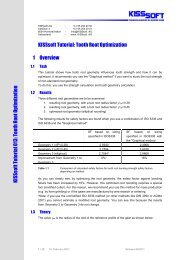
1 Overview<br />
1.1 Task<br />
This tutorial shows how tooth root geometry influences tooth root stress and how it can be optimized. It<br />
recommends you use the "graphical method", if you want to study the tooth root stress of non-standard root<br />
geometry.<br />
To do this, you use the strength calculation and tooth geometry calculation.<br />
1.2 Results<br />
Three different root geometries are to be examined:<br />
1. resulting root geometry, with a tool root radius factor * fP =0.38<br />
2. resulting root geometry, with a tool root radius factor * fP =0.45<br />
3. optimized root geometry (elliptical rounding)<br />
The following results for safety factors are found when you use a combination of ISO 6336 and ISO 6336<br />
and the "graphical method":<br />
SF based on sizing specified<br />
in ISO 6336<br />
Geometry 1 (* fP=0.38) 2.5937 2.4948<br />
Geometry 2 (* fP=0.45) 2.7585 2.6747<br />
Geometry 3 (elliptical) 2.7584* 2.9514<br />
Improvement from Geometry 1 to Geometry 3 6%* 18%<br />
SF based on sizing specified in ISO 6336<br />
with the graphical method<br />
Figure 1.<br />
Comparison of calculated safety factors for tooth root bending strength safety factors depending on method.<br />
As you can clearly see, by optimizing the root geometry, the safety factor against bending failure was<br />
increased by 16%. However, this optimized root rounding requires a special tool (modified cutter). For this<br />
reason, we recommend you use this method for mass production (e.g. by form grinding) or if the gears are<br />
manufactured by wire erosion or sintering.<br />
* Note: If you use the unmodified ISO 6336 method (or other methods like DIN3990 or <strong>AG</strong>MA2001) you<br />
cannot estimate a modified root geometry. You can see this because the results from Geometry 2 to<br />
Geometry 3 do not change.<br />
1.3 Theory<br />
The value fP is the root radius of the reference profile of the gear as shown below:<br />
Figure 2.<br />
Reference profile of the gear, fP<br />
05.03.2013 3 / 14
The strength rating specified in ISO 6336 uses only a single point in the root where factors YF and YS are<br />
calculated. This point is defined by the contact between a tangent to the root intersecting the symmetry line<br />
at a 30° angle and the root itself. YF and YS are then calculated as shown in formulas (2) and (3). The<br />
resulting tooth root stress is then calculated in accordance with formula (1).<br />
(1)<br />
(2)<br />
(3)<br />
Figure 3. Calculating the tooth root stress as specified in ISO 6336.<br />
The actual construction of the root rounding therefore implies a larger or smaller degree of error.<br />
By taking the actual root form into account, the <strong>KISSsoft</strong> system allows you to perform the calculation at<br />
each point in the tooth root area for tooth form YF and the stress correction factor YS. In this case, the point<br />
at which the product of YF*YS reaches the maximum is taken as the point where the strength rating is<br />
performed.<br />
This is the only method that allows you to evaluate the effect of optimized root roundings.<br />
1.4 Other contents of this tutorial<br />
In section 2, the root safety factor is calculated according to the unmodified ISO 6336 method (Method B).<br />
However, you cannot use this method to take into account the effect of root optimization. The root safety<br />
factor is therefore only calculated for Geometry 1 and 2.<br />
In section 3, the root safety is then calculated using the graphical method (an optional modification to ISO<br />
6336 by <strong>KISSsoft</strong>). Here you can clearly see the effect of optimized root rounding.<br />
The comparison between the calculated results is shown in Figure 1.<br />
Further explanations and comments are given in section 4.<br />
All calculations/changes are performed only for gear 1.<br />
05.03.2013 4 / 14
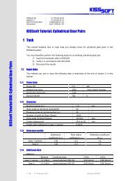
2 Strength calculation as specified in ISO 6336<br />
2.1 For Geometry 1 (* fP =0.38)<br />
To open the example used in this tutorial, click "File/Open" and select "CylGearPair 1 (spur gear)" or click<br />
the "Examples" tab.<br />
Figure 4.<br />
Opening example calculation "CylGearPair 1 (spur gear)".<br />
The selected calculation method is ISO 6336, Method B. Click on the "Reference profile" tab to see which<br />
reference profile is being used. This example used a standard reference profile (1.25/0.38/1.00) as<br />
specified in ISO 53.2 profile A.<br />
Figure 5.<br />
Selected calculation method<br />
Figure 6.<br />
Standard reference profile for the first calculation<br />
05.03.2013 5 / 14
Figure 7. Result of calculating the safety factor of the tooth root stress in Gear 1<br />
The resulting tooth form is displayed in a graphics window. Click the button (upper right marking) to make it<br />
into a floating window and enlarge it. You can save the tooth forms so they can be compared later on. To do<br />
this, follow the steps marked in Figure 8.<br />
1<br />
3<br />
2<br />
5<br />
4<br />
Figure 8. Resulting tooth form with * fP =0.38<br />
05.03.2013 6 / 14
2.2 For Geometry 2 (* fP =0.45)<br />
The first step is to determine the maximum possible value for * fP . To do this, go to the drop-down list for<br />
the reference profile and select "Own Input". Click the Sizing button to determine a value of 0.4710 for * fP .<br />
The maximum permitted value is for * fP =0.4710.<br />
Figure 9.<br />
Modification of * fP<br />
This changes the input value for * fP . Then input * fP =0.45. Now click<br />
calculation. No warning messages are issued here.<br />
or press "F5" to perform the<br />
05.03.2013 7 / 14
Figure 10. Result of root safety with changed * fP =0.45 for Gear 1<br />
The safety factor of the root has increased:<br />
In the 2D graphic you can see both the old and new tooth form (use the "+"/"-" buttons to change its size).<br />
The blue curve is the tooth form generated with * fP =0.45. The black curve is the old tooth form with<br />
* fP =0.38, which was saved previously.<br />
Figure 11.<br />
Comparison of tooth roundings (old/black with * fP=0.38, new/blue with * fP=0.45)<br />
05.03.2013 8 / 14
2.3 For Geometry 3 (elliptical root rounding)<br />
You cannot perform this calculation because the strength rating specified in ISO 6336 is only based on the<br />
reference profile. Therefore you cannot use ISO 6336 to calculate the effect of a modified root rounding that<br />
is not based on a normal rack profile. For this reason, you should use the "Graphical method" as shown in<br />
the next section.<br />
3 Strength calculation using the "Graphical method“<br />
3.1 For Geometry 1 (* fP =0.38)<br />
In the "Reference profile" tab, reset the value for * fP to * fP =0.38. Then go to the "Rating" tab.<br />
Figure 12.<br />
Resetting * fP to * fP=0.38<br />
Now activate the "using graphical method" option. Go to the "Rating" tab and click on "Details". This<br />
opens the "Define details of rating" window. There, select "using graphical method" from the drop-down<br />
list next to tooth form factors YF, YS. Click "OK" to confirm the entry and close the window.<br />
Figure 13.<br />
Activating the calculation method using the "graphical method"<br />
Then click<br />
somewhat lower.<br />
or press "F5" to repeat the strength calculation. Note that the safety factor is now<br />
05.03.2013 9 / 14
Figure 14.<br />
Calculation of resulting safety factor for Gear 1 with *fP =0.38 using the "graphical" method<br />
3.2 For Geometry 2 (* fP =0.45)<br />
In the "Reference profile" tab, now reset the value for * fP to * fP =0.45. Click "Σ" or press F5 to perform the<br />
strength calculation.<br />
<br />
Figure 15.<br />
Calculation of resulting safety factor for Gear 1 with *fP =0.45 using the "Graphical" method<br />
<br />
3.3 For Geometry 3 (elliptical root rounding)<br />
To add the elliptical root modification, start the tooth form calculation by clicking on the "<strong>Tooth</strong> form" tab.<br />
Figure 16.<br />
Opening the tooth form calculation<br />
In the next window you can see how to add the "Elliptic root modification" operation by clicking the righthand<br />
mouse button on "automatic".<br />
05.03.2013 10 / 14
Figure 17.<br />
Adding an elliptical root modification<br />
Then click to the right of the "Modification starting at diameter" field to define where the elliptical root<br />
modification is to start. Click the right-hand mouse button on the "Elliptic root modification" icon and<br />
select "Choose as result" to ensure that this tooth is modified.<br />
Figure 18.<br />
Starting the modification, enabling the calculation step.<br />
Back in the "Basic data" tab, you can now calculate the strength (after the tooth geometry has been<br />
calculated) by clicking<br />
or pressing "F5". The safety factor for gear 1 has changed:<br />
Figure 19.<br />
Result of the calculation with optimized tooth root rounding.<br />
05.03.2013 11 / 14
4 Notes and explanations<br />
4.1 Calculation step: "automatic"<br />
When you open the tooth form calculation the first manufacturing step is already visible and the default<br />
setting is "automatic".<br />
Figure 20.<br />
Default setting in the tooth form calculation<br />
This step is based on the reference profile defined in the "Reference profile" tab.<br />
Therefore, when you add the elliptical root modification, there is either no difference (or only a minor<br />
difference), depending on whether * fP =0.38 or * fP =0.45 has already been defined in the "Reference<br />
profile" tab. This is because the elliptical modification is only the second manufacturing step (the first one is<br />
a generating step that uses the "automatic" setting based on the reference profile defined in the "Reference<br />
profile" tab). This is why the newly calculated tooth form is so similar.<br />
However, if you change the "Coefficient for curvature" value, you can modify the shape of the elliptical<br />
curve. The "Arc length on the root diameter" value defines the length of a circular arc between two<br />
elliptical sections.<br />
Figure 21.<br />
Factor for elliptical root rounding<br />
Figure 22.<br />
Defining the factor for root rounding and arc length on the root radius<br />
05.03.2013 12 / 14
4.2 Calculating internal gears<br />
For internal gears, the calculation according to DIN 3990, ISO 6336 and <strong>AG</strong>MA 2001 is actually quite<br />
inaccurate (however, the situation will be better in the version of ISO 6336:2006). For this reason we<br />
recommend you use the "graphical method" if you want to calculate internal gears. You will need module<br />
ZA15 if you want to use the "graphical method".<br />
4.3 Calculating a tool profile to manufacture an elliptical root<br />
To calculate the geometry of a tool that will, in turn, generate all the calculation steps including the elliptical<br />
modification, you must:<br />
Click the right-hand mouse button after the "Elliptic root modification" operation to add the "Calculate<br />
reference profile" operation<br />
and then select this as the result.<br />
Figure 23.<br />
Add "Calculate reference profile" operation<br />
Figure 24. Select Manufacturing Gear 1.<br />
05.03.2013 13 / 14
Figure 25. Display Manufacturing Gear 1<br />
Finally, display the tool. In the graphics window, select "Cutter/Tool Gear 1" from the list to display the tool<br />
geometry. You can now export the tool geometry in order to create the tool.<br />
Figure 26. Displaying the selection Cutter/Tool Gear 1.<br />
Figure 27.<br />
Displaying the cutter/tool.<br />
You can now save the tool as DXF or IGES.<br />
05.03.2013 14 / 14