KISSsoft Tutorial: Sizing a Planetary Gear Set for ... - KISSsoft AG
KISSsoft Tutorial: Sizing a Planetary Gear Set for ... - KISSsoft AG
KISSsoft Tutorial: Sizing a Planetary Gear Set for ... - KISSsoft AG

You also want an ePaper? Increase the reach of your titles
YUMPU automatically turns print PDFs into web optimized ePapers that Google loves.
<strong>KISSsoft</strong> <strong>Tutorial</strong> 012: <strong>Sizing</strong> a Fine Pitch <strong>Planetary</strong> <strong>Gear</strong> <strong>Set</strong><br />
<strong>KISSsoft</strong> <strong>AG</strong> - +41 55 254 20 50<br />
Uetzikon 4 - +41 55 254 20 51<br />
8634 Hombrechtikon - info@<strong>KISSsoft</strong>. <strong>AG</strong><br />
Switzerland - www. <strong>KISSsoft</strong>. <strong>AG</strong><br />
<strong>KISSsoft</strong> <strong>Tutorial</strong>: <strong>Sizing</strong> a <strong>Planetary</strong> <strong>Gear</strong> <strong>Set</strong> <strong>for</strong> Precision<br />
Mechanics<br />
1 Task<br />
To size a planetary gear set with an input torque of 450 Nmm (0.45 Nm) at 10000 rpm. The<br />
nominal transmission ratio is 4.25. The required service life is 20,000 hours, with an application<br />
factor of K A =1.25.<br />
The package size (external diameter of the gear rim) is 35 mm, including 3 mm material<br />
between the root diameter and the external diameter. The gears are made of sintered<br />
powdered metal. The module must be greater than 0.5 mm (due to manufacturing<br />
requirements). The tooth <strong>for</strong>m must be optimized to make full use of the fact that the gears are<br />
not manufactured using the generation process. The calculation method used here is the one<br />
specified in <strong>AG</strong>MA: 2101-D04.<br />
2 Starting <strong>KISSsoft</strong><br />
2.1 Starting the software<br />
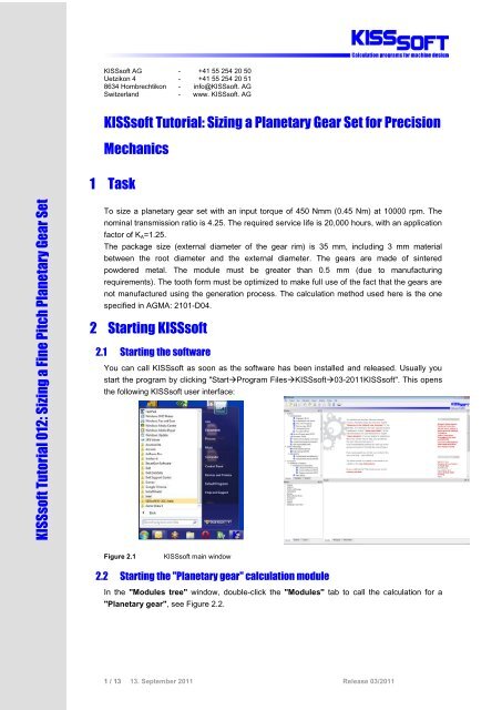
You can call <strong>KISSsoft</strong> as soon as the software has been installed and released. Usually you<br />
start the program by clicking "StartProgram Files<strong>KISSsoft</strong>03-2011<strong>KISSsoft</strong>". This opens<br />
the following <strong>KISSsoft</strong> user interface:<br />
Figure 2.1<br />
<strong>KISSsoft</strong> main window<br />
2.2 Starting the "<strong>Planetary</strong> gear" calculation module<br />
In the "Modules tree" window, double-click the "Modules" tab to call the calculation <strong>for</strong> a<br />
"<strong>Planetary</strong> gear", see Figure 2.2.<br />
1 / 13 13. September 2011 Release 03/2011
Figure 2.2<br />
Selecting the "<strong>Planetary</strong> gear" calculation module from the "Modules" window<br />
2.3 Basic settings<br />
If the <strong>AG</strong>MA 2101-method is used <strong>for</strong> a planetary gear set, it is a good idea to activate the<br />
graphical method <strong>for</strong> factor Y (as this influences the calculation of root stress). To do this, go to<br />
the "Strength" tab, select "Details" and click the "Pair data" group. Activate the graphical<br />
method and define where the <strong>for</strong>ce is to be applied. As some of the solutions found during the<br />
draft design phase will have geometric errors (which cause <strong>KISSsoft</strong> to cancel the calculation<br />
automatically), we recommend you go to the module specific settings and activate "Allow large<br />
profile shift" and "Don't abort when geometry errors occur". This allows the <strong>KISSsoft</strong> software<br />
to continue with a calculation even if an error has occurred. See Figure 2.3.<br />
2 / 13 13. September 2011 Release 03/2011
Figure 2.3 "Define details of strength" and "Module specific settings" <strong>for</strong> this example<br />
2.4 <strong>Set</strong>ting constraints<br />
Go to the "Geometry" tab and input the required number of planets (Figure 2.4). The load<br />
distribution coefficient K increases the load placed on an individual planet. In this case, set it to<br />
1.0.<br />
Figure 2.4<br />
Defining the number of planets<br />
Figure 2.5<br />
Defining the load distribution coefficient<br />
2.5 Rough sizing<br />
Click [OK] to return to the main dialog. Open Rough sizing and specify the required calculation<br />
method (1) and the material (2). Then input the application factor (3) and the service life (4).<br />
Click the radio button next to the Power field to define the load (5), see Figure 2.7.<br />
3 / 13 13. September 2011 Release 03/2011
Figure 2.6<br />
Call the Rough sizing function<br />
Figure 2.7<br />
<strong>Set</strong>ting the materials, calculation method, application factor and required service life<br />
Specifying the load<br />
To specify the unit used <strong>for</strong> torque, click the right-hand mouse button on the appropriate field<br />
(Figure 2.8).<br />
Figure 2.8<br />
Specifying the unit <strong>for</strong> torque<br />
Define the reference gear (1), the calculated value (2) (if the torque and number of rotations<br />
have been defined, the per<strong>for</strong>mance will be calculated) and input the data <strong>for</strong> the number of<br />
rotations and torque (3) (see Figure 2.9).<br />
Figure 2.9<br />
Specifying the load<br />
Then enter the nominal transmission ratio (6).<br />
4 / 13 13. September 2011 Release 03/2011
Figure 2.10<br />
Rough sizing settings<br />
If <strong>KISSsoft</strong> were to calculate a design with the basic settings, it would result in an extremely<br />
small module. For this reason, you should lower the value range <strong>for</strong> the number of teeth from 9<br />
to 12 (7), to <strong>for</strong>ce <strong>KISSsoft</strong> to select a larger module. It is not usually necessary to change the<br />
default value <strong>for</strong> the number of teeth. Then click "OK" to close the input window.<br />
Figure 2.11<br />
Rough sizing default settings "Limit geometry"<br />
Click [Calculate] (8). Look at the results.<br />
5 / 13 13. September 2011 Release 03/2011
Figure 2.12<br />
Calculating rough sizing<br />
If you are happy with this, return to the dialog by closing the editor and clicking on [Accept] (9),<br />
see Figure 2.13.<br />
Figure 2.13<br />
Rough sizing result<br />
The main dialog is now filled with data from the solution generated by the Rough sizing<br />
function. As the module is smaller than 1.0, we recommend you use a different standard <strong>for</strong> the<br />
tolerances. To do this, go to the "Tolerances" tab. In the Tolerances dialog, select the tooth<br />
thickness deviation "DIN 58405 10e" <strong>for</strong> each gear, Figure 2.14. Here, 10 indicates the quality<br />
(interval width), where 10 means "lower quality". The letter "e" represents the definition of the<br />
interval limit and there<strong>for</strong>e also the backlash.<br />
6 / 13 13. September 2011 Release 03/2011
Figure 2.14<br />
<strong>Set</strong>ting the tolerance<br />
After you have defined the tolerances, you may want to input a better value <strong>for</strong> the facewidth (in<br />
this example we are leaving the values unchanged (1), see Figure 2.15. Click [Calculate F5]<br />
(2). You now see the first results of the roughly sized planetary gear set in the "Results<br />
overview" (2a) (Figure 2.15).<br />
2.6 Fine <strong>Sizing</strong><br />
This completes the presizing step. This is used to provide the Fine sizing function with values<br />
that are approximately the correct size <strong>for</strong> the subsequent processing steps. Now, to generate<br />
an optimized solution, click the Fine sizing (3) button Figure 2.15.<br />
Figure 2.15<br />
Calculate, check the results and call the Fine sizing function<br />
Firstly, check the value <strong>for</strong> the nominal conversion (this may have changed slightly during<br />
Rough sizing) (1). Then input the required values range and the increments <strong>for</strong> the module<br />
(<strong>KISSsoft</strong> will automatically select very small values) (2). Define the target value <strong>for</strong> the gear<br />
rim reference circle (3). To define the correct diameter, deduct 3 mm of the material underneath<br />
the root diameter twice from the gear's external diameter (35 mm). This gives a measurement<br />
of 29 mm. Then reduce this again by a further 2*1 mm <strong>for</strong> the dedendum (this value does not<br />
need to be correct because the permissible deviation is set to 10%).<br />
Click the "<strong>Sizing</strong> button" <strong>for</strong> the center distance (4) to display the possible value range <strong>for</strong> this<br />
value. In order to <strong>for</strong>ce the gear's root diameter to be small enough to ensure sufficient material<br />
7 / 13 13. September 2011 Release 03/2011
emains below the tooth root, you must input a suitable value in the relevant field (here: 35-2*3<br />
mm = 29 mm) (5), see Figure 2.16.<br />
Figure 2.16<br />
<strong>Set</strong>tings <strong>for</strong> Fine sizing<br />
As you are using the graphical method to determine the root stress, you must calculate the<br />
tooth <strong>for</strong>m <strong>for</strong> every solution that is found. To do this, click [Conditions II] (6).<br />
Figure 2.17<br />
Calculating mesh stiffness<br />
Click [Calculate] to start Fine sizing. If a solution is found (if not, a message appears to tell you<br />
no solutions could be found), click on the "Graphics" tab.<br />
If you now only want to include the safety factors, Solution 18 looks very promising: the safety<br />
factor <strong>for</strong> the root is large enough and the flank safety is more than adequate. As you can<br />
usually improve tooth root safety by modifying the root geometry, flank safety is more important<br />
in this case.<br />
8 / 13 13. September 2011 Release 03/2011
Normally, you would also check the other criteria (such as transverse contact ratio, specific<br />
sliding, etc.). As this is closely connected with the particular problem you are dealing with, this<br />
issue is not discussed here, and the tutorial moves on to solution 18. Please refer to the<br />
tutorials list at the end of this document <strong>for</strong> more in<strong>for</strong>mation about the Fine <strong>Sizing</strong> function.<br />
Figure 2.18<br />
Graphical display of the results<br />
Go to the Fine <strong>Sizing</strong> "Results" tab and select a variant by double-clicking on variant 18 or<br />
clicking the [Accept] button (Figure 2.19).<br />
Figure 2.19<br />
Selecting a solution<br />
When you return to the main dialog (Figure 2.20) the "Results overview" window gives a brief<br />
overview, whereas the entire data record <strong>for</strong> the selected solution is displayed in the report.<br />
Click "F6" to display the report. At this point, you have finished sizing the planetary gear.<br />
9 / 13 13. September 2011 Release 03/2011
Figure 2.20<br />
Overview of calculation results<br />
2.7 Optimizing the tooth <strong>for</strong>m<br />
After the gear layout process is finished, the next step is to optimize the tooth <strong>for</strong>m. As the<br />
gears are not manufactured by the generation process (in this case sintered), you can make<br />
modifications at no additional cost. This section describes the most commonly used<br />
modifications to the tooth <strong>for</strong>m of sintered gears. For more details on this topic, please refer to<br />
the tutorials list at the end of this document.<br />
To input the tooth <strong>for</strong>m modification, click the "Calculation" -> "Modifications" menu option.<br />
See Figure 2.21.<br />
Figure 2.21<br />
Activating the "Modifications" tab page<br />
To improve initial tooth contact, and to take into account the shrinkage associated with the<br />
sintering manufacturing process, you must define tip rounding. To do this, select "Rounding"<br />
from the drop-down list <strong>for</strong> "Type of tip modification", and input a value (here: 0.08 mm,<br />
which is already fairly large) in the input field <strong>for</strong> <strong>Gear</strong>s 1 through 3 (see Figure 2.22).<br />
10 / 13 13. September 2011 Release 03/2011
Figure 2.22<br />
Tip modification "rounding" the tooth <strong>for</strong>m<br />
You can now input the tooth <strong>for</strong>m modification in the active "Modifications" tab. Click the<br />
"<strong>Sizing</strong> button" to open the "<strong>Sizing</strong> modifications" window (Figure 2.23).<br />
Figure 2.23<br />
Defining profile correction details<br />
The "Short profile correction, curved" is selected <strong>for</strong> the tip relief to keep the contact impact<br />
as small as possible. This should then be carried out on <strong>Gear</strong> 2. Select "Short profile<br />
correction, curved" and click the "Calculate" button. <strong>KISSsoft</strong> calculates a draft design <strong>for</strong><br />
the tip relief, which (automatically) starts halfway between the single tooth contact point, with a<br />
value based on the calculated tooth bending value.<br />
The best solution <strong>for</strong> the root is usually an ellipse with a larger radius at the end of the involute<br />
and a smaller radius in the middle of the root area between two teeth. To calculate this, click<br />
the "Tooth <strong>for</strong>m" tab and then click "Insert elliptical root modification". Next click the "<strong>Sizing</strong><br />
button" to display a suggested value <strong>for</strong> the elliptical <strong>for</strong>m.<br />
11 / 13 13. September 2011 Release 03/2011
Figure 2.24<br />
"Elliptical root modification" adds the alternative<br />
After this definition has been per<strong>for</strong>med <strong>for</strong> all the gears, either click the "" icon or press "F5".<br />
Figure 2.25<br />
Calculating and displaying the tooth <strong>for</strong>m<br />
In the next dialog, activate the collision check.<br />
12 / 13 13. September 2011 Release 03/2011
Figure 2.26 Activating collision check and displaying pair 1<br />
Click the button (2) and select "Apply flank (right)". Now you should see small black dots<br />
at the points where the two flanks contact each other. A black dot means "meshing or almost<br />
meshing", and a red dot means "collision".<br />
Figure 2.27<br />
Automatic connection of flanks, zoom and collision check<br />
Use the "+"/"-" button to zoom in or out, click the right-hand mouse button to open the menu<br />
and, finally, click the buttons to animate the graphic. Check whether any of the<br />
modifications cause a problem. See Figure 2.27.<br />
When you are satisfied with the result, go back to the main dialog. Click [Calculate F5] and use<br />
the root safety factor to check whether or not the modifications have improved the root<br />
strength.<br />
2.8 Current tutorials<br />
The tutorials listed below include additional details about particular topics that are mentioned in<br />
this document:<br />
- <strong>Tutorial</strong> 009, "Fine <strong>Sizing</strong> of Cylindrical <strong>Gear</strong>s"<br />
- <strong>Tutorial</strong> 011: "Tooth Form Optimizations, Tooth Form Modifications"<br />
13 / 13 13. September 2011 Release 03/2011