Gearing analysis for wind turbine, seen as a process - KISSsoft AG
Gearing analysis for wind turbine, seen as a process - KISSsoft AG
Gearing analysis for wind turbine, seen as a process - KISSsoft AG

Create successful ePaper yourself
Turn your PDF publications into a flip-book with our unique Google optimized e-Paper software.
Showing the teeth at the <strong>wind</strong>…<br />
H. Dinner, <strong>KISSsoft</strong> <strong>AG</strong>, hanspeter.dinner@<strong>KISSsoft</strong>.ch<br />
<strong>Gearing</strong> <strong>analysis</strong> <strong>for</strong> <strong>wind</strong> <strong>turbine</strong>, <strong>seen</strong> <strong>as</strong> a <strong>process</strong><br />
Wind <strong>turbine</strong>s are getting bigger, <strong>wind</strong> <strong>turbine</strong> gearboxes more<br />
complex, their number of gears incre<strong>as</strong>es and a gearbox failure –<br />
and, with it, the resulting operational stop– is more and more<br />
expensive.<br />
At the same time, the <strong>wind</strong> farm operator depends from the <strong>wind</strong><br />
<strong>turbine</strong> manufacturer and the latter is then again dependent from<br />
gearbox manufacturers. On the other hand, the gearbox<br />
manufacturer h<strong>as</strong> a knowledge head-start in comparison with <strong>wind</strong><br />
<strong>turbine</strong> manufacturer and he, in turn, knows more about the power<br />
trains in its equipment than the operator. This situation prompts<br />
disputes and opens the flood gates between the partners.<br />
The objective is to drive the partners towards an interchange of knowledge allowing at<br />
the same time a participating responsibility. An interchange of knowledge can only exist<br />
when all partners do have a sufficient amount of it.<br />
The objective of this article is, with the example of a toothing calculation, to delineate<br />
the necessary knowledge b<strong>as</strong>is <strong>for</strong> a fair and qualified dialog.<br />
1 Problem Definition<br />
In the <strong>wind</strong> <strong>turbine</strong> gearbox dimensioning and verification, there are some specific problems<br />
atypical of transmissions in the power generation field:<br />
- loading: fluctuating torques, excessive overloads due to vibration, torque change of<br />
sense, site-dependent loading, etc.<br />
- power: high torques at low speeds, high power density<br />
- operation: temperature fluctuations, cold starts, idling, loading at standstill<br />
- gearbox dimensions: lightweight design required, soft bearing, bending torque on the<br />
input shaft (especially <strong>for</strong> three-point bearing)<br />
- accessibility: the gearbox is of difficult access, tool transportation is difficult.<br />
Besides the technical side, some questions on the collaboration between the gearbox supplier<br />
and the buyer frequently pop up:<br />
- methodology safety in the calculation and its documentation<br />
- safer data flow within an between all the partners involved<br />
- understandability of <strong>as</strong>sumptions and calculation methodologies<br />
- consensus between the partners concerning <strong>as</strong>sumptions and characteristic values to<br />
be attained<br />
- quick verification of the manufacturer’s gearbox calculation by the buyer.<br />
Dem-Wind-die-Zähne-gezeigt-Format-<strong>KISSsoft</strong>-E.doc 1 of 18
A few economical <strong>as</strong>pects are also atypical:<br />
- <strong>wind</strong> <strong>turbine</strong> gearboxes have atypically long delivery times, the market is rarefied<br />
- the number of suppliers is comparatively small, a few renown ones are strongly<br />
<strong>as</strong>sociated with equipment manufacturers<br />
- equipment and gearboxes are certified by third parties<br />
- high number of damages connected to high costs<br />
It is thus most interesting to incorporate all partners in a dialog so that all of them could<br />
understand, <strong>as</strong>sume and share the risks. Prerequisite to this understanding is a think-tank of<br />
the peculiarities of <strong>wind</strong> <strong>turbine</strong> gearboxes and transmissions in general, <strong>as</strong> well <strong>as</strong> effective<br />
methodologies and tools, in order to permit relevant in<strong>for</strong>mation interchange on the gearboxes<br />
employed.<br />
2 Wind Turbine Gearboxes<br />
2.1 Systematic<br />
Most <strong>wind</strong> <strong>turbine</strong> installations are equipped with similar gearboxes; typical are three-stage<br />
spur wheel gearbox (lower capacity area), one-stage planetary gearbox with two spur wheel<br />
stages (middle capacity area) and two-stage planetary gearbox with one spur wheel stage<br />
(higher capacity area). In addition to that, there are at present some interesting variants, see<br />
Fig. 2.2-1.<br />
The majority of <strong>wind</strong> <strong>turbine</strong> installations h<strong>as</strong> one rotor only that generally is up<strong>wind</strong><br />
oriented. Likewise, most installations have one generator only, i. e., the gearbox h<strong>as</strong> exactly<br />
one input and one output.<br />
Conceivably and partially implemented, are the four combinations in Fig. 2.1-1. The<br />
execution with several generators or rotors is unusual; the author does not know of any<br />
installation with several rotors and several generators.<br />
Types Single output Multiple output<br />
Single Input<br />
One Rotor, one Generator<br />
Standard c<strong>as</strong>e<br />
One Rotor, multiple<br />
Generators; e. g. Clipper<br />
Multiple Inputs<br />
Multiple Rotors, one<br />
Generator; e. g. Kowintec<br />
Multiple Rotors, multiple<br />
Generators; unknown<br />
Figure 2.1-1 Possible Design Concepts in respect to Power Flow<br />
The <strong>wind</strong> <strong>turbine</strong> gearbox mission is that of trans<strong>for</strong>ming the low speeds and high torques at<br />
the gearbox input into higher speeds and lower torques at the output. Thus, according to their<br />
kinematics type, <strong>wind</strong> <strong>turbine</strong> gearboxes can be cl<strong>as</strong>sified <strong>as</strong> follows:<br />
- standard gearboxes that constantly trans<strong>for</strong>m input torque and speed values into those<br />
at the output<br />
- torque-limiting gearboxes can control or, at le<strong>as</strong>t, limit the output torque (and with it<br />
the input torque). The speed is thereby not controlled.<br />
- The most complex <strong>for</strong>ms of gearbox are the CVTs that permit the control of the<br />
gearbox output speed and torque –within a determined range.<br />
Dem-Wind-die-Zähne-gezeigt-Format-<strong>KISSsoft</strong>-E.doc 2 of 18
2.2 Concepts<br />
Following figures show an –incomplete– overview of realized or investigated gearbox<br />
concepts. The one- and two-stage planetary gearboxes (with two or one downstream spur<br />
wheel stages), in particular, constitute the standard today. With the time, and with the incre<strong>as</strong>e<br />
of power, the number of gearing meshes also incre<strong>as</strong>ed and the toothing calculation got more<br />
complex.<br />
Spur wheel stage, also with Power split<br />
Planetary gear stage with a Ring wheel stage.<br />
Test installation in Holland<br />
One Planetary gear stage, two Spur wheel<br />
stages<br />
Two Planetary gear stages, one Spur wheel<br />
stage<br />
Dem-Wind-die-Zähne-gezeigt-Format-<strong>KISSsoft</strong>-E.doc 3 of 18
Planetary gear stage, fixed Planet:<br />
Renk Aerogear<br />
Planetary gear stage, fixed Ring wheel<br />
Power Split, several Generators: Clipper<br />
Two inputs: Luv and Lee Rotor, Kowintec<br />
Planetary coupled gearbox: MA<strong>AG</strong><br />
Differential gearbox: Bosch Rexroth<br />
Dem-Wind-die-Zähne-gezeigt-Format-<strong>KISSsoft</strong>-E.doc 4 of 18
M<br />
G<br />
Hydraulic torque limiting: Henderson Gearbox<br />
Torque limiting: Electric motor (M).<br />
Test installation in Orkney Island<br />
Hydrodynamic differential??? gearbox:<br />
Voith WinDrive<br />
Figure 2.2-1 Several Gearbox Concepts<br />
Hydrostatic differential??? gearbox:<br />
Windtec/Wikov/Orbital2<br />
3 Toothing Calculation <strong>for</strong> Wind Turbine Gearboxes<br />
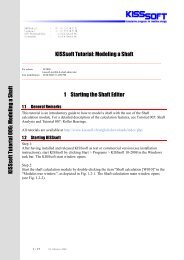
3.1 Toothing calculation methodology<br />
Toothing calculation should not be reduced to strength verification; this proof, is surely<br />
necessary and is explicitly <strong>as</strong>ked <strong>for</strong>, but only represents one of the steps in the “Toothing<br />
calculation” methodology.<br />
Toothing calculation must be considered <strong>as</strong> a <strong>process</strong> that, starting with load <strong>as</strong>sessment,<br />
looks <strong>for</strong> an optimal toothing solution, analyzes it and produces an extensive documentation<br />
<strong>for</strong> the production, quality control and certification.<br />
Dem-Wind-die-Zähne-gezeigt-Format-<strong>KISSsoft</strong>-E.doc 5 of 18
Nachrechnung<br />
Verification Optimization<br />
Optimierung Production Herstellung<br />
Dimensioning<br />
Auslegung<br />
Export→CAD<br />
Loading<br />
Bel<strong>as</strong>tung<br />
Certification<br />
Zertifizierung<br />
Documentation<br />
Dokumentation<br />
Figure 3.1-1 Toothing Calculation Methodology<br />
Fig. 3.1-1 above shows a minimum of steps to be carried out in a toothing calculation <strong>process</strong>.<br />
Not included in it are, particularly, the determination of the upstream load spectra and the<br />
resulting downstream hardware preparation and tests. The following sections illustrate the<br />
individual steps of this <strong>process</strong>. However, because of the complexity of this topic, a<br />
comprehensive description of these steps is not possible in the scope of this article.<br />
3.2 Kinematics <strong>analysis</strong><br />
Normally, determining the loads acting on the gearbox is not the responsibility of the gearbox<br />
manufacturer; however, he must investigate to what extent a change in the handed over load<br />
<strong>as</strong>sumptions would result in a change of the toothing dimensioning.<br />
A load spectra reduced damage equivalent (torque and speed at the gearbox input) will thus<br />
be used <strong>for</strong> determining the toothing dimensioning. For the gear dimensioning, specifically<br />
<strong>for</strong> epicyclic gears, this load must then be converted into the gear meshing power (<strong>as</strong> opposed<br />
to blind and coupling power). This kinematics <strong>analysis</strong> can already be rather costly in c<strong>as</strong>e of<br />
differential gearboxes, gearboxes with power splits or CVT gearboxes. The presentation of a<br />
few power flows in the following figures illustrates this in a more clear way.<br />
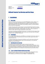
In KISSsys, it is possible to use complex kinematics analyses to calculate the effective mesh<br />
powers <strong>for</strong> the toothing dimensioning. This simulation software calculates the power flow in<br />
power trains and links this simulation to a strength calculation of the machine elements<br />
involved in the power train. It is thus possible to parameterize complete gearboxes /<br />
transmission power trains and analyze them <strong>for</strong> strength and service life. Among other things,<br />
KISSsys offers the user a quick and detailed parameter study of complete gearboxes /<br />
transmission power trains in order to be able to efficiently compare several design variants.<br />
KISSsys uses <strong>KISSsoft</strong> <strong>for</strong> the strength and service life calculation of the various machine<br />
elements.<br />
Dem-Wind-die-Zähne-gezeigt-Format-<strong>KISSsoft</strong>-E.doc 6 of 18
Figure 3.2-1 Above: Wind Turbine Gearbox Calculation Model in KISSsys.<br />
Bottom left: Power Flow Diagram of a one Stage Planetary Gearbox with two Spur Wheel<br />
Stages.<br />
Bottom right: Power Flow Diagram of a Bosch Rexroth Differential Gearbox (Three<br />
Planetary Gear Stages and one Spur Wheel Stage).<br />
3.3 Dimensioning<br />
Once the gear meshing power is known, the dimensioning of the relevant toothing parameters<br />
(number of teeth, module and pressure angle) can be carried out. With it, following<br />
parameters will be considered:<br />
- attainable toothing quality<br />
Dem-Wind-die-Zähne-gezeigt-Format-<strong>KISSsoft</strong>-E.doc 7 of 18
- material characteristics<br />
- reference transmission ratio and acceptable deviation<br />
- requested service life / safety<br />
- installation conditions / mountability<br />
It is especially important to consider here, the mountability conditions of the first planetary<br />
stage, because both the ring gear maximum possible diameter (manufacturing) and the<br />
necessary planet wheel diameter (space <strong>for</strong> the planet bearings) restrict the manufacturer’s<br />
liberty.<br />
3.4 Toothing optimization<br />
The toothing can afterwards be optimized, the variation of the following parameters being the<br />
most usual:<br />
- tooth depth (reaching an optimum transverse contact ratio)<br />
- helix angle (reaching an optimum overlap ratio)<br />
- addendum modification (influences specific slippage and strength)<br />
- fillet optimization (e. g. bigger radius by tool module different than gear module)<br />
- profile- and face modification (improving contact pattern, reducing meshing shock)<br />
- surface treatment (hardening, smoothing)<br />
Some selected points will be shortly described in the following sections.<br />
3.4.1 Tooth depth optimization<br />
The use of a standard reference profile, e. g., with a tooth depth of 2.25 mm, normally results<br />
in a transverse contact ratio between 1.00 and 2.00. This means that, during a certain time one<br />
tooth, and during a certain time two teeth are meshed. With it, the meshing stiffness value<br />
permanently changes from single to double. This change can create vibration. The goal is to<br />
reach a whole-number overlapping in order to guarantee that, at any time, the same number of<br />
teeth is meshed. This can be achieved by augmenting the tooth depth resulting in a reduced<br />
gearing vibration.<br />
Stiffness<br />
Single Meshing<br />
(N/mm/µm<br />
)<br />
Stiffness<br />
Single Meshing<br />
(N/mm/µm<br />
)<br />
Number of Meshing Points (-)<br />
Number of Meshing Points (-)<br />
Figure 3.4-1 Meshing Stiffness Progression Changes due to a higher Tooth Depth<br />
Dem-Wind-die-Zähne-gezeigt-Format-<strong>KISSsoft</strong>-E.doc 8 of 18
3.4.2 Profile modification<br />
Wind <strong>turbine</strong> gearboxes environments demand low noise levels. The vibrations provoked by<br />
the gears are undoubtedly a cause <strong>for</strong> the noise. Thus, the goal must be, on one hand, to<br />
maintain transmission errors <strong>as</strong> low <strong>as</strong> possible and, on the other hand, to reduce meshing<br />
shock. The tooth depth dimensioning and the tip relief (amount, type and height) are here of<br />
the utmost importance.<br />
Figure 3.4-2 Meshing Line under Load. Left: Premature Meshing with a non-modified Toothing (Meshing<br />
Line Inflection). Center: Toothing with a short, linear Tip Relief (6.2 µm and 5.0 µm).<br />
Right: Toothing with progressive Tip Relief (9.3 µm and 7.5 µm).<br />
End Stage of a 3.6 MW Installation.<br />
The premature meshing (meshing line prolongation) in the figure on the left, leads to a so<br />
called meshing shock. This can be reduced with tip relief, the meshing line showing no longer<br />
the characteristic prolongation. However, <strong>for</strong> a linear tip relief, the meshing line shows a<br />
discontinuity (center figure); this abrupt change in the rotation angle could create vibration.<br />
This will be avoided with a progressive tip relief (figure on the right).<br />
The profile modification also leads to a smaller pressure at the start of the meshing thus<br />
reducing the scuffing risk, see Fig. 3.5-4.<br />
3.4.3 Correction along the tooth width<br />
In non-modified toothings, due to shaft strain, bearing play, tooth deflection, <strong>as</strong> well <strong>as</strong> shaft<br />
bearing displacement (bearing and housing) an uneven load distribution appears along the<br />
tooth width. As a result of this, the whole toothing strength will be reduced in certain highly<br />
loaded are<strong>as</strong> (Fig. 3.4-3, below left). Correcting the tooth profile along its width (typically a<br />
combination of helix angle correction, end relief and crowning) it is possible to achieve that<br />
the gears under load neatly fit together and the load, <strong>as</strong> much <strong>as</strong> possible, be uni<strong>for</strong>mly<br />
distributed along the tooth width (Fig. 3.4-3, below right). The calculation of these corrections<br />
is one of the most demanding t<strong>as</strong>ks <strong>for</strong> which the gearbox manufacturer experience is<br />
indispensable.<br />
Dem-Wind-die-Zähne-gezeigt-Format-<strong>KISSsoft</strong>-E.doc 9 of 18
Line Load<br />
Load Distribution<br />
Line Load<br />
Load Distribution<br />
Longitudinal Axis Y<br />
Longitudinal Axis Y<br />
Figure 3.4-3 1.5MW Gearbox Output Shaft, Load Distribution along the Width. Left: without Corrections.<br />
Right: with Helix Angle Correction and corrected Toothing Crowning<br />
3.5 Stress <strong>analysis</strong><br />
Now, after having optimized the dimensioned toothing and reached a final dimensioning, it is<br />
necessary to check whether it complies with the required safety coefficients. Now, this stress<br />
<strong>analysis</strong> should not be carried out with the equivalent-damage individual loads <strong>as</strong> previously<br />
done <strong>for</strong> the dimensioning any more; the <strong>analysis</strong> must be executed using a damage<br />
calculation with a load spectrum. The toothing <strong>analysis</strong> is done according to the standards and<br />
guidelines valid at the moment. In the following, knowledge of these calculation<br />
methodologies is expected and it will be especially referred to calculations diverging from the<br />
standards that are meaningful <strong>for</strong> the <strong>wind</strong> <strong>turbine</strong> gearboxes toothing.<br />
3.5.1 Tooth root strength<br />
Normally, the standards underestimate the contact ratio effect, especially where a production<br />
precision is required –<strong>wind</strong> <strong>turbine</strong> gearboxes. Following figures show the effective stress<br />
situation (Flank: light blue; Root 1: violet; Root 2: red) in comparison with the meshing<br />
calculated values according to DIN 3990. The root stress is especially overestimated. The<br />
figures show the comparison between the root stress, according to the standard, and the same<br />
stress taking into consideration the load distribution. In addition, the comparison between<br />
both figures explicitly shows the influence of the pitch error on the stress situation.<br />
Hertz Stress and maximum Root Stress during Meshing<br />
L<strong>as</strong>t Calculation Situation (Z12), Date/Time:<br />
Hertz Stress and maximum Root Stress during Meshing<br />
Hertz Stress and maximum Root Stress during Meshing<br />
L<strong>as</strong>t Calculation Situation (Z12), Date/Time:<br />
Hertz Stress and maximum Root Stress during Meshing<br />
Figure 3.5-1 Load Distribution Influence over several Teeth at Stress Level.<br />
Left: <strong>for</strong> Quality 7.<br />
Right: <strong>for</strong> Quality 5. End Stage of a 3.6 MW Installation, ε α =1.73.<br />
Dem-Wind-die-Zähne-gezeigt-Format-<strong>KISSsoft</strong>-E.doc 10 of 18
Following modifications are recommended <strong>for</strong> the ring wheel root strength calculation:<br />
- calculation at 60° Tangent contact point, taking into consideration the actually root<br />
contour produced by shaping cutter such <strong>as</strong>, e. g., suggested in the present editions of<br />
the ISO 6336:2006 (or VD I 2737)<br />
- exact tooth profile calculation on the b<strong>as</strong>is of a meshing simulation with the tool <strong>for</strong><br />
the calculation of Y F and Y S along the entire fillet (“graphical method”, see influence<br />
on Fig. 3.5-2)<br />
- taking into consideration the influence of the ring wheel wall thickness in the tooth<br />
root stress according to VDI 2737.<br />
The comparison in Fig. 3.5-2 shows that the ring toothing strength calculations in the root<br />
area according to DIN 3990 and ISO 6336:1996 / ISO 6336:2006 give different results.<br />
3<br />
1.15<br />
2.5<br />
2<br />
1.5<br />
ISO6336 C<br />
ISO6336 B<br />
ISO6336 (extended) (erweitert) B<br />
Graphical Method<br />
1.1<br />
1.05<br />
1<br />
0.95<br />
ISO6336 (erweitert) (extended) B<br />
Grafische Graphical Methode<br />
1<br />
0.9<br />
0.5<br />
0.85<br />
0<br />
YF3 YS3 SF3<br />
0.8<br />
YF3 YFS3 SF3<br />
Figure 3.5-2 Calculation Methodology Influence upon the Ring Toothing calculated Root Safety.<br />
Left: Reference Profile = 1.25/0.38/1.00. Right: Reference Profile = 1.40/0.38/1.25.<br />
3.5.2 Tooth flank strength<br />
Due to the flank’s pressure load, a shear stress progression builds up in depth, with a<br />
maximum just under the surface. In c<strong>as</strong>e of overload, the excessive shear stress leads to<br />
cracks under the surface that can originate 0.5 to 1 mm material erosion (pitting). When<br />
tempering the tooth flank, the c<strong>as</strong>e hardening depth (EHT in German) must be higher than the<br />
maximum shear stress depth. On the other hand, out of cost considerations, the EHT must be<br />
kept <strong>as</strong> small <strong>as</strong> possible; the shear stress progression calculation (Fig. 3.5-3) being thus of<br />
utmost interest.<br />
C<strong>as</strong>e Hardening Depth Pair 1 (Wheel 1 Material me<strong>as</strong>ured Value)<br />
Name: Ex. 1 (Spur wheel), Date 15.01.2006/21:27:03<br />
Hardening Depth Pair 1 (Wheel 1 Material me<strong>as</strong>ured Value)<br />
Depth (my)<br />
Shear Stress Progression (determining the Hardening Depth)<br />
(σH=1020.8 N/mm 2 ; ro_r= 19.3 mm)<br />
Maximum Shear Stress Depth (mm) 0.274<br />
EHT Suggestion : 0548 mm<br />
(Suggestion acc. alternating Flexure Stress, Niemann : 0.922<br />
mm)<br />
(Suggestion acc. <strong>AG</strong>MA 2101. Fig. 13: Normal 0.879 mm,<br />
Heavy 1.326 mm)<br />
!! For production with grinding allowance, indicate the half on<br />
the drawing) !!<br />
Shear Stress Progression ( on the B<strong>as</strong>is of the Flank Pressure)<br />
Material me<strong>as</strong>ured Value (from Datab<strong>as</strong>e)<br />
Vickers Hardness (HV)<br />
Figure 3.5-3 Hertz Stress Progression from the Toot Surface → Interior.<br />
Dem-Wind-die-Zähne-gezeigt-Format-<strong>KISSsoft</strong>-E.doc 11 of 18
3.5.3 Scuffing<br />
ISO 6336 h<strong>as</strong> no proof of scuffing facility; in this c<strong>as</strong>e, it is usual to proceed according to<br />
DIN 3990, Part 4. Both <strong>AG</strong>MA6006 and the GL guidelines <strong>as</strong>k <strong>for</strong> a reduction of one unit in<br />
the calculation of the lubricant’s scuffing load level according to FZG (German Research<br />
Center <strong>for</strong> Gears and Gearboxes). Since modern oils with EP (Extreme Pressure) addictives<br />
have scuffing load levels >12, and the calculation methodologies only consider load levels up<br />
to 12, this limitation being practically less relevant. The calculation of the safety against<br />
scuffing is b<strong>as</strong>ed on the estimation of the temperature at the tooth contact, this temperature<br />
depending upon the pressure and the slippage speed. Scuffing preferably occurs in the tip and<br />
root are<strong>as</strong> where high relative speeds are present. In order to reduce the contact <strong>for</strong>ce in this<br />
meshing area, a tip relief (and/or a root relief) is introduced whose influence on the contact<br />
temperature is shown in Fig. 3.5-4.<br />
Temperature at Tooth Contact (θB)<br />
Temperature at Tooth Contact [θB ]<br />
Temperature at Tooth Contact (θB)<br />
Date/Time:<br />
Temperature at Tooth Contact [θB ]<br />
θB<br />
Help<br />
θB<br />
Help<br />
Maximum Contact Temperature 301.2<br />
Scuffing Probability 26.09 %<br />
XSi<br />
XSi<br />
Figure 3.5-4 Fl<strong>as</strong>h Temperature Reduction from 300 °C to 230 °C due to Tip Relief. 3.6 MW End Stage.<br />
Calculation according to <strong>AG</strong>MA 925-A03.<br />
3.5.4 Micropitting<br />
By insufficient lubrication due to high loading or unfavourable operation parameters, the<br />
friction coefficient between tooth flanks incre<strong>as</strong>es due to the tooth contact roughness<br />
(boundary friction, µ=0.2 to 0.4, in contr<strong>as</strong>t to viscous friction µ=0.05). Due to the higher<br />
friction <strong>for</strong>ce, a shear stress develops on the tooth surface that can already exceed a critical<br />
value even <strong>for</strong> an uncritical torque <strong>for</strong> the building of micropitting. This overstressing leads to<br />
material erosion (depth approx. 10 to 20 µm, over a zone of approx. 20 to 100 µm) showing <strong>as</strong><br />
a grayish discolouration on the tooth surface. The resulting profile irregularities lead to a<br />
higher tooth load (K Hα , K Fα , K ν , noise incre<strong>as</strong>es) and a higher risk of pitting. The specific<br />
lubrication film thickness λ –the quotient between the lubrication film thickness and the<br />
surface roughness– serves to me<strong>as</strong>ure the risk of micropitting. The calculation follows<br />
<strong>AG</strong>MA 925, or FVA (German Research Association <strong>for</strong> Propulsion Technology) worksheets<br />
54/259; an ISO Standard is in preparation.<br />
Dem-Wind-die-Zähne-gezeigt-Format-<strong>KISSsoft</strong>-E.doc 12 of 18
Help<br />
Help<br />
Help<br />
Figure 3.5-5 3.6 MW Wind Turbine Gearbox: λ Values <strong>for</strong> the 1 st and 2 nd Planet (Sun-Planet Mesh) and<br />
Spur Wheel Stages<br />
3.5.5 Static proof of strength<br />
It is also necessary to carry out a toothing static proof of strength <strong>for</strong> pl<strong>as</strong>tic strain or rupture.<br />
Since the standards do not cover the cl<strong>as</strong>sic static proof, this will frequently be done <strong>as</strong> a<br />
proof of fatigue with a number of cycles = 1. However, a proof against yield- and rupture<br />
limits would be more meaningful.<br />
3.6 Checking the manufacturing<br />
It is also necessary to check how the toothing is to be manufactured, if it is b<strong>as</strong>ed on the<br />
desired tooth profile, in order to calculate the geometry required <strong>for</strong> manufacturing the<br />
necessary tools. Once decided upon the various production steps, it is necessary to calculate<br />
the resulting tooth profile with the help of a final simulation of the manufacturing, see Fig.<br />
3.5-6, at left. This can now deviate from the desired tooth profile, see Fig. 3.5-6, at right, and<br />
it must be checked (concerning strength, meshing interference, etc.) whether these deviations<br />
are acceptable. It is not enough to specify a toothing and send it <strong>for</strong> production; also here, a<br />
dialog involving calculation, construction and production is indispensable.<br />
Figure 3.6-1 Left: Manufacturing Simulation with three Tools (Pre-machining, Protuberance Cutter,<br />
Grinding Wheel). Right: Difference between theorectical and manufactured Root Profile.<br />
3.7 Data transfer to CAD plat<strong>for</strong>ms<br />
Now, the calculated toothing data can be sent to the CAD plat<strong>for</strong>m that will produce the<br />
drawings; here, gear data and the 2-D and 3-D data are especially interesting. The goal is to<br />
display in the toothing production drawings all relevant details, exactly <strong>as</strong> previously<br />
Dem-Wind-die-Zähne-gezeigt-Format-<strong>KISSsoft</strong>-E.doc 13 of 18
dimensioned and optimized. This demands a smooth data transfer from the toothing software<br />
to the CAD plat<strong>for</strong>m.<br />
Figure 3.7-1 KISSsys 3D-Gearbox Geometry: Transfer to a CAD Plat<strong>for</strong>m (e. g. Pro-Engineer).<br />
Figure 3.7-2 <strong>KISSsoft</strong> 2D-Toothing and Die Stamp Data: Transfer from the Calculation to a CAD<br />
Plat<strong>for</strong>m (here, Inventor).<br />
3.8 Calculation <strong>for</strong> the certification<br />
For the gearbox certification it necessary to be sure that the previously mentioned proofs are<br />
sufficient <strong>for</strong> the guidelines and standards. The certifier’s guidelines prescribe, partially in<br />
detail, how the mentioned verifications have to be carried out. The relevant guidelines<br />
especially establish the so-called K factors. Also prescribed are the target safety factors<br />
where<strong>as</strong> these, once again, depend upon the characteristics of the employed material which<br />
are not prescribed.<br />
3.8.1 Application factor K A<br />
A load spectra <strong>for</strong> the toothing dimensioning can be e<strong>as</strong>ily replaced by a nominal load and an<br />
application factor K A . The calculation of K A can, e. g., be done according to DIN3990, Part 6,<br />
Method III or to <strong>AG</strong>MA6006 simplified <strong>as</strong> follows:<br />
Dem-Wind-die-Zähne-gezeigt-Format-<strong>KISSsoft</strong>-E.doc 14 of 18
T<br />
eq<br />
K<br />
A<br />
= ,<br />
Tn<br />
T<br />
eq<br />
⎛<br />
⎜<br />
= ⎜<br />
⎜<br />
⎝<br />
∑ i<br />
i<br />
∑<br />
n * T<br />
i<br />
n<br />
i<br />
p<br />
i<br />
⎞<br />
⎟<br />
⎟<br />
⎟<br />
⎠<br />
1/ p<br />
p = S-N Curve Slope<br />
n i = Stage i Load Change<br />
T i = Stage i Torque<br />
Because the equivalent torque calculation <strong>for</strong> the toothing dimensioning with the derived K A ,<br />
does not consider fatigue strength it is thus rather conservative.<br />
The S-N Curve slope p changing <strong>for</strong> different materials and treatments, <strong>as</strong> well <strong>as</strong>, <strong>for</strong> root<br />
and flank, several different K A values (one <strong>for</strong> each p) have to be determined that which is not<br />
very practical. There<strong>for</strong>e, the calculation should generally ignore the application factor and<br />
use instead a damage accumulation, e. g., <strong>as</strong> in DIN 3990 or ISO 6336:2006, Part 6.<br />
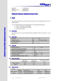
3.8.2 Load distribution factor Kγ<br />
Because of manufacturing tolerances and strains, the load distribution among the load paths<br />
(planets) is not balanced. There<strong>for</strong>e, <strong>for</strong> the calculation of planetary gear trains a load<br />
distribution factor K γ will be used. The suggested values <strong>for</strong> <strong>wind</strong> <strong>turbine</strong> gearboxes strongly<br />
vary according to the source, see Fig. 3.8-1. To improve the load distribution between the<br />
planets, it is possible to equip individual planet gear set components (sun, ring and planet)<br />
with el<strong>as</strong>tic or floating bearings, e. g., floating sun shafts, or el<strong>as</strong>tic ring bearings. Another<br />
solution would be the use of a flexible planet bearing <strong>as</strong> an el<strong>as</strong>tic element. The Flexpin<br />
allows planet radial or circumferential alignments. The effect of this flexible planet bearing<br />
can be <strong>seen</strong> on the chart of Fig. 3.8-1 <strong>as</strong> the difference between the lines “MA<strong>AG</strong> without and<br />
with Flexpin”, which are b<strong>as</strong>ed partly on me<strong>as</strong>urements and partly on experience values. The<br />
K γ values proposed by MA<strong>AG</strong> will surely be included in the new <strong>AG</strong>MA 6123 version<br />
1.6<br />
1.5<br />
K gamma<br />
1.4<br />
[-]<br />
GL<br />
DNV<br />
<strong>AG</strong>MA6123<br />
MA<strong>AG</strong> ohne w/o Flexpin / <strong>AG</strong>MA6123, Appl. Level 3<br />
MA<strong>AG</strong> mit w/ Flexpin / <strong>AG</strong>MA6123, Appl. Level 4<br />
IEC 61400<br />
1.3<br />
1.2<br />
1.1<br />
1<br />
3 4 5 6 7 8<br />
Anzahl Planeten [-]<br />
Figure 3.8-1 Load Distribution Factor <strong>as</strong> a Function of the Number of Planets<br />
Me<strong>as</strong>urements show that K γ values sink with incre<strong>as</strong>ing loads because manufacturing<br />
tolerances loose importance when compared with the load-dependent strains. However, they<br />
are expensive and only admit conclusions <strong>for</strong> the product K v *K γ . The previously given<br />
approximate values can only be taken <strong>as</strong> upper limits. With low K γ values being possible,<br />
solutions with more than three planets are <strong>for</strong> the first time economically fe<strong>as</strong>ible. For<br />
Dem-Wind-die-Zähne-gezeigt-Format-<strong>KISSsoft</strong>-E.doc 15 of 18
instance, with five planets and an actual me<strong>as</strong>ured K γ =1.12, it is possible to transmit 95% of<br />
the torque possible with seven equally wide planets and a K γ =1.50 (conservative <strong>as</strong>sumption /<br />
guidelines). This, again, permits higher stage ratios and provides more space <strong>for</strong> the design of<br />
the planet carrier.<br />
3.8.3 Face load factor K β<br />
The meshing <strong>for</strong>ce distribution over the toothing width and its effect upon the flank- (K Hβ )<br />
and root (K Fβ ) loads are described by the face load factor K β . Besides the simplified<br />
calculation described in the standards, the guidelines <strong>for</strong> <strong>wind</strong> <strong>turbine</strong> gearboxes demand a<br />
detailed load distribution numerical calculation when a required minimum value (K β ≥1.15)<br />
should be further reduced. For this purpose, there are several calculation programs available<br />
such <strong>as</strong> LVR, Rikor, Plankorr or LPD.<br />
It is possible to achieve a uni<strong>for</strong>m load on the tooth width with a toothing correction. In<br />
general, thin toothing face load factors are more favourable than those <strong>for</strong> wider ones. Once<br />
again is the Flexpin mentioned here since it keeps the planets from overturning under load<br />
(thus directly reducing K β ) and, by a more favourable K γ permits using five or seven thinner<br />
planets (with lower K β ). These self-centering systems also permit using still lower K β values<br />
(1.30 lead to unacceptable contact patterns that must also be detected in practice<br />
(test run-up). I. e., that already realized gearboxes have K β values between 1.10 and 1.30. . In<br />
practice, the face load factor K β (especially under load) is mostly lower than the values<br />
obtained in the calculation.<br />
3.8.4 Transverse load factor K α<br />
The transverse load factor takes into consideration the load incre<strong>as</strong>e in the flank (K Hα ) and in<br />
the root (K Fα ) because of pitch errors and irregular load distribution over several teeth being<br />
meshed. The calculation is done according to ISO 6336. The use of K α =1 is accepted <strong>for</strong> the<br />
toothing qualities required <strong>for</strong> <strong>wind</strong> <strong>turbine</strong> gearboxes (e. g., minimum quality 6 <strong>for</strong> external<br />
toothing, <strong>as</strong> per GL guidelines). The face load factor K β having a strong influence on the<br />
stress behaviour, <strong>for</strong> the exact calculation of the product K β *K α , a 3D contact <strong>analysis</strong> is<br />
required <strong>as</strong> an alternative and, thus, a combined factor K αβ will be used.<br />
3.8.5 Dynamic factor K v<br />
The dynamic factor K ν takes into consideration the load incre<strong>as</strong>e on the flank (K Hν ) and on<br />
the root (K Fv ) on account of toothing rigidity variations during the meshing. When the<br />
frequency of the toothing rigidity variations / speed is directly comparable to the meshing’s<br />
own frequency, additional dynamic <strong>for</strong>ces will occur. The calculation is done following ISO<br />
6336, Method B and distinguishes three speed are<strong>as</strong> (sub critical: N1) defined by the reference speed N (pinion speed n 1 compared with the<br />
resonance speed n E1 ) where N takes into consideration the reduced toothing m<strong>as</strong>s m Red and<br />
the toothing rigidity c γ .<br />
n1<br />
mred<br />
N = = 2πn1<br />
z1<br />
, K v<br />
= f (N)<br />
n<br />
c<br />
E1<br />
γ<br />
Dem-Wind-die-Zähne-gezeigt-Format-<strong>KISSsoft</strong>-E.doc 16 of 18
Because of the low speed, <strong>wind</strong> <strong>turbine</strong> gearboxes will be operated in the sub critical area and<br />
the K ν values will be accordingly set. The certification directives <strong>for</strong> <strong>wind</strong> <strong>turbine</strong> gearboxes,<br />
<strong>as</strong> well <strong>as</strong> the relevant standards estipulate a K ν ≥ 1.05 value. Should a lower value be used, a<br />
me<strong>as</strong>urement or more detailed calculation must be carried out.<br />
3.8.6 Required calculation safeties<br />
The required, calculation safeties are specified in guidelines. Determining the really required<br />
safeties is difficult and requires a comprehensive field experience. The know-how of these<br />
required safety factors represents <strong>for</strong> the gearbox manufacturer an enormous capital because it<br />
cannot be bought; only acquired.<br />
Guideline Proof according to S F (Fatigue / static) S H (Fatigue / static)<br />
<strong>AG</strong>MA6006 <strong>AG</strong>MA2101-C95 1.0 1.0<br />
<strong>AG</strong>MA6006 ISO6336 1.56 1.25<br />
GL Guidelines ISO6336 1.5 (1.4) 1.2 (1.0)<br />
Danish WT Cert. Doc. ISO6336 1.45 1.2<br />
IEC61400 ISO6336 1.56 1.25<br />
3.9 Documentation<br />
All calculations have to be documented so that they can be submitted to and checked by the<br />
certification. Documentation costs incre<strong>as</strong>e steadily and is necessary here that it could be<br />
automatically produced.<br />
4 Summary<br />
4.1 Is that all?<br />
No. Toothing calculation runs an important role in gearbox dimensioning influencing also the<br />
design of other components (shafts, bearings, unions, etc.), housing and lubrication. Their<br />
dimensioning and calculation is, once again an own procedure whose description is far<br />
beyond the scope of this article.<br />
Furthermore, it is clear that calculation on its own does not lead to a trouble-free gearbox<br />
operation. In this context, it is especially necessary to mention gearbox test, operation<br />
management and control. The calculation is just to be <strong>seen</strong> <strong>as</strong> an isolated, necessary but not<br />
sufficient step in a higher-ranking procedure.<br />
4.2 Calculation methodology safety<br />
Not only the gearbox manufacturer but also the suppliers, installation manufacturers and<br />
operators should know the calculation methodology. Only then could they be in an equalrights<br />
position to have a qualified dialog with the actual suppliers and customers. The risks<br />
inherent to the acceptance officer of a gearbox or installation will then be transparent and<br />
could be mutually shared.<br />
The calculation <strong>process</strong> should be <strong>as</strong> such implemented and controlled. Still, it is<br />
un<strong>for</strong>tunately that, also among gearbox manufacturers, it will not consistently be <strong>seen</strong> <strong>as</strong> a<br />
Dem-Wind-die-Zähne-gezeigt-Format-<strong>KISSsoft</strong>-E.doc 17 of 18
<strong>process</strong> which must work in all departments in a self-evident way. P<strong>as</strong>t are the days in which<br />
the calculation department calculates something, then the manufacturer builds something else<br />
and in the end, the production produces something different. To avoid this, we need tools that<br />
could be employed during the entire <strong>process</strong>. These tools must also be in a position to convey<br />
in<strong>for</strong>mation in a safe way from component suppliers (e. g., gear manufactures) to gearbox<br />
manufacturers and then, via equipment manufacturers, to the end customers (the operators).<br />
The latter would thus be able to take care of maintenance and repairs under their own<br />
responsibility because all the relevant in<strong>for</strong>mation will be available, even when the<br />
maintenance contract with the equipment manufacturer h<strong>as</strong> expired.<br />
4.3 What next?<br />
In gearbox manufacturing, the calculation must be conceived <strong>as</strong> a <strong>process</strong> which also involves<br />
manufacturing and production. By many gearbox manufacturers it is not yet introduced the<br />
need <strong>for</strong> all departments to intensively intercommunicate, being still strongly obstinate in<br />
pursuing the department-thinking mentality with the result of losing much in<strong>for</strong>mation and<br />
energy at the many interfaces. .<br />
In the <strong>wind</strong> energy area, the calculation conception must also include, in addition to the<br />
gearbox manufacturer, the load team, the equipment manufacturer, certification officers and<br />
the end customer. Besides this, it is necessary some ef<strong>for</strong>t on part of the equipment<br />
manufacturer and, especially, the operator, in order to be able to collaborate in this <strong>process</strong>.<br />
The dialog with the gearbox manufacturer requires a considerably amount of knowledge<br />
which the certification officers must possess, by the equipment manufacturers strongly<br />
disappears and, by the operator rarely exists.<br />
This ought to be changed!<br />
5 Bibliography<br />
U. Giger, G.P. Fox, Leistungsverzweigte Planetengetriebe in Windenergieanlagen mit<br />
flexibler Planetenlagerung, ATK03<br />
R. Grzybowski, B. Niederstucke, Betriebsfestigkeitsberechnung von Getrieben in<br />
Windenergieanlagen mit Verweildauerkollektiven, Allianz Report 2004<br />
R. Poore, T. Lettenmaier, Alternative Design Study Report: Wind PACT Advanced Wind<br />
Turbine Drive Train Designs Study, NREL/SR-500-33196<br />
H. Dinner, Gleichberechtigter Dialog als Erfolgsrezept, Verzahnungsberechnung für<br />
Windenergieanlagengetriebe, Antriebstechnik 5/2006<br />
F. D. Krull, T. Siegenbruck, Windenergieanlagen <strong>for</strong>dern hohe Leistungsdichten, Ermittlung<br />
der Breitenl<strong>as</strong>tverteilung in Planetengetrieben, Antriebstechnik 9/2004<br />
H. Dinner, Integrated Dimensioning, Optimization, Verification and producing Drawings <strong>for</strong><br />
Wind <strong>turbine</strong> gearboxes, Planet Trains, Haus der Technik, März 07<br />
Dem-Wind-die-Zähne-gezeigt-Format-<strong>KISSsoft</strong>-E.doc 18 of 18