Systematic Gearbox Sizing and Verification The task ... - KISSsoft AG
Systematic Gearbox Sizing and Verification The task ... - KISSsoft AG
Systematic Gearbox Sizing and Verification The task ... - KISSsoft AG

You also want an ePaper? Increase the reach of your titles
YUMPU automatically turns print PDFs into web optimized ePapers that Google loves.
<strong>Systematic</strong> <strong>Gearbox</strong> <strong>Sizing</strong> <strong>and</strong> <strong>Verification</strong><br />
<strong>Systematic</strong> <strong>Gearbox</strong> <strong>Sizing</strong> <strong>and</strong> <strong>Verification</strong><br />
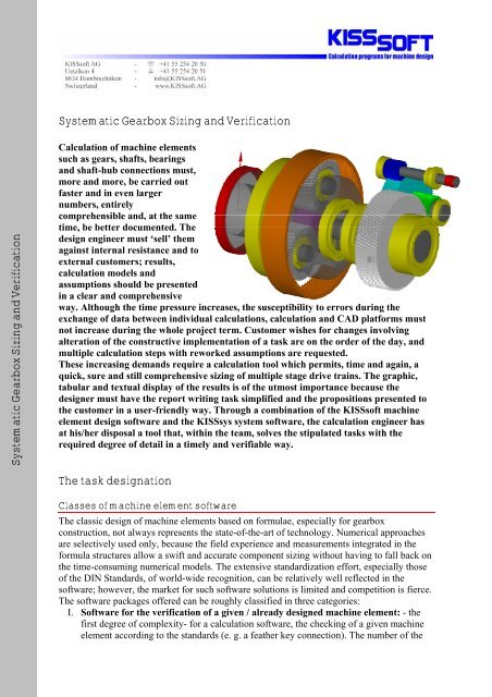
Calculation of machine elements<br />
such as gears, shafts, bearings<br />
<strong>and</strong> shaft-hub connections must,<br />
more <strong>and</strong> more, be carried out<br />
faster <strong>and</strong> in even larger<br />
numbers, entirely<br />
comprehensible <strong>and</strong>, at the same<br />
time, be better documented. <strong>The</strong><br />
design engineer must ‘sell’ them<br />
against internal resistance <strong>and</strong> to<br />
external customers; results,<br />
calculation models <strong>and</strong><br />
assumptions should be presented<br />
in a clear <strong>and</strong> comprehensive<br />
way. Although the time pressure increases, the susceptibility to errors during the<br />
exchange of data between individual calculations, calculation <strong>and</strong> CAD platforms must<br />
not increase during the whole project term. Customer wishes for changes involving<br />
alteration of the constructive implementation of a <strong>task</strong> are on the order of the day, <strong>and</strong><br />
multiple calculation steps with reworked assumptions are requested.<br />
<strong>The</strong>se increasing dem<strong>and</strong>s require a calculation tool which permits, time <strong>and</strong> again, a<br />
quick, sure <strong>and</strong> still comprehensive sizing of multiple stage drive trains. <strong>The</strong> graphic,<br />
tabular <strong>and</strong> textual display of the results is of the utmost importance because the<br />
designer must have the report writing <strong>task</strong> simplified <strong>and</strong> the propositions presented to<br />
the customer in a user-friendly way. Through a combination of the <strong>KISSsoft</strong> machine<br />
element design software <strong>and</strong> the KISSsys system software, the calculation engineer has<br />
at his/her disposal a tool that, within the team, solves the stipulated <strong>task</strong>s with the<br />
required degree of detail in a timely <strong>and</strong> verifiable way.<br />
<strong>The</strong> <strong>task</strong> designation<br />
Classes of machine element software<br />
<strong>The</strong> classic design of machine elements based on formulae, especially for gearbox<br />
construction, not always represents the state-of-the-art of technology. Numerical approaches<br />
are selectively used only, because the field experience <strong>and</strong> measurements integrated in the<br />
formula structures allow a swift <strong>and</strong> accurate component sizing without having to fall back on<br />
the time-consuming numerical models. <strong>The</strong> extensive st<strong>and</strong>ardization effort, especially those<br />
of the DIN St<strong>and</strong>ards, of world-wide recognition, can be relatively well reflected in the<br />
software; however, the market for such software solutions is limited <strong>and</strong> competition is fierce.<br />
<strong>The</strong> software packages offered can be roughly classified in three categories:<br />
I. Software for the verification of a given / already designed machine element: - the<br />
first degree of complexity- for a calculation software, the checking of a given machine<br />
element according to the st<strong>and</strong>ards (e. g. a feather key connection). <strong>The</strong> number of the
commercial solutions available is considerable <strong>and</strong> a good dozen products share this<br />
market.<br />
II. Expert system for the sizing <strong>and</strong> optimization of machine elements: - the second<br />
degree of complexity- since software is supposed to help the manufacturer already at the<br />
sizing stage, verification alone is mostly not of much help. Here is where expert systems<br />
with their most sought-after functionalities, offer the user solutions to a given problem –<br />
e. g. the design of a machine element. Only few products consistently cover this<br />
customers' need; however, only the fewest packages offer sizing <strong>and</strong> look-up functions.<br />
III. Systems approaches to the analysis of complete systems: - the third degree of<br />
complexity- software packages that deal with the whole system <strong>and</strong> power trains instead<br />
of resolving separate calculations only. <strong>The</strong> author only knows of three commercial<br />
solutions in the field of machine elements / gearboxes, world-wide. Following, one of<br />
these systems will be described.<br />
Interestingly, the number of solutions combining the advantages of all three classes is very<br />
small; one (the only one?) is described here.<br />
<strong>KISSsoft</strong>’s machine element design software is conceived to support the user in the sizing,<br />
optimization as well as in the verification stages. It covers the entire calculation process, from<br />
problem definition down to documentation <strong>and</strong>, therefore, can be considered as an expert<br />
system (category II, above).<br />
Especially the toothing calculation - the most extensive calculation in <strong>KISSsoft</strong>- cannot be<br />
reduced to a proof of strength (as it would have been according to the first degree of<br />
complexity); admittedly, this proof is surely necessary <strong>and</strong> is explicitly asked for, however, it<br />
only constitutes a single step in the entire toothing calculation process. <strong>The</strong> toothing<br />
calculation must be understood as a process that, starting at a load determination, looks for an<br />
optimum toothing solution, analyses it <strong>and</strong> produces extensive documentation for the<br />
production, quality control <strong>and</strong> certification.<br />
Nachrechnung<br />
<strong>Verification</strong> Optimization<br />
Optimierung Production Herstellung<br />
Dimensioni Auslegung <strong>Sizing</strong><br />
Export→CAD<br />
Loading<br />
Belastung<br />
Certification Zertifizierung<br />
Documentation<br />
Dokumentation<br />
Figure 1.1-1 Toothing Calculation Methodology<br />
This process is integrated in the individual <strong>KISSsoft</strong> calculations. However, <strong>KISSsoft</strong> looks at<br />
individual machine elements in every case without their interaction.<br />
From the expert system to the system approach<br />
<strong>The</strong>refore, the goal is to offer tools for the analysis of complete systems. However, the<br />
constraint that the tool be also suitable for the sizing <strong>and</strong> verification of individual machine<br />
elements should be included, which is not always the necessary or desired purpose of the<br />
whole system. <strong>The</strong>refore, the user asks for a system software (class III) without having to give<br />
up the advantages of the simple calculation software (class I) <strong>and</strong> of the expert tool (class II).<br />
<strong>Systematic</strong> <strong>Gearbox</strong> <strong>Sizing</strong> <strong>and</strong> <strong>Verification</strong>-Format-<strong>KISSsoft</strong>-E.doc 2 of 23
<strong>KISSsoft</strong> <strong>AG</strong> has solved this <strong>task</strong> definition in a unique way:<br />
- <strong>KISSsoft</strong>’s machine element design software covers not only the simple verification<br />
but also the sizing <strong>and</strong> optimization costly procedures<br />
- the user can determine the number of <strong>KISSsoft</strong> visible windows, thus configuring the<br />
software according to the particular needs<br />
- with it, <strong>KISSsoft</strong> can be configured <strong>and</strong> used as a class I or II software<br />
- KISSsys groups together in a system any number of <strong>KISSsoft</strong> calculations <strong>and</strong>,<br />
together with <strong>KISSsoft</strong>, constitutes a class III software solution<br />
- time <strong>and</strong> again, the user may go back to its trusted <strong>KISSsoft</strong> calculations, thus<br />
minimizing the effort of switching from an expert system to a system solution.<br />
Figure 1.2-1 <strong>KISSsoft</strong> simple Toothing Calculation Configuration, e. g., for Toothing <strong>Verification</strong>. It<br />
exactly requires three Data Entry Windows only (Tabs: Basis Data, Reference Profile <strong>and</strong><br />
Tolerances, marked in Red). With this, it corresponds to a Class I Software<br />
<strong>Systematic</strong> <strong>Gearbox</strong> <strong>Sizing</strong> <strong>and</strong> <strong>Verification</strong>-Format-<strong>KISSsoft</strong>-E.doc 3 of 23
Figure 1.2-2 <strong>KISSsoft</strong> Expert Configuration, for <strong>Sizing</strong> <strong>and</strong> Optimizing. Furthermore, other Calculations<br />
(additional Tabs marked in Red), several Graphics are displayed <strong>and</strong> additional <strong>Sizing</strong><br />
Functions as separate Windows are activated. With this, it corresponds to a Class II<br />
Software<br />
I.e., <strong>KISSsoft</strong>, as design software for individual machine elements can be used either as a<br />
st<strong>and</strong>-alone solution OR in connection with the KISSsys system add-on. This basic approach,<br />
although it combines the advantages of all approaches <strong>and</strong> offers the user a maximum of<br />
flexibility, was hardly ever implemented in the design of machine elements. This<br />
circumstance explains the success of the “<strong>KISSsoft</strong> + KISSsys” t<strong>and</strong>em.<br />
<strong>KISSsoft</strong> Files<br />
with Gear Wheel<br />
Pairs, Stage1<br />
<strong>KISSsoft</strong> Files<br />
with Gear Wheel<br />
Pairs, Stage 2<br />
<strong>KISSsoft</strong> Files<br />
with Shaft<br />
Geometries, Input<br />
Shaft<br />
<strong>KISSsoft</strong> Files<br />
with Shaft<br />
Geometries,<br />
Intermediate<br />
Shaft<br />
<strong>KISSsoft</strong> Files<br />
with Shaft<br />
Geometries,<br />
Output Shaft<br />
<strong>KISSsoft</strong> Files for<br />
Rolling Bearing<br />
Pair, Input Shaft<br />
<strong>KISSsoft</strong> Files for<br />
Rolling Bearing<br />
Pair, Intermediate<br />
Shaft<br />
<strong>KISSsoft</strong> Files for<br />
Rolling Bearing<br />
Pair, Output Shaft<br />
Figure 1.2-3 <strong>KISSsoft</strong> <strong>and</strong> KISSsys Interaction illustrating a System of separate Calculations.<br />
<strong>Systematic</strong> <strong>Gearbox</strong> <strong>Sizing</strong> <strong>and</strong> <strong>Verification</strong>-Format-<strong>KISSsoft</strong>-E.doc 4 of 23
<strong>The</strong> additional cost of modelling<br />
Characteristically, the operating effort increases from software class I to software class III. Of<br />
course, the power flow modelling in KISSsys also takes time <strong>and</strong> a learning effort. Should or<br />
could this not be afforded, there are application libraries offering solutions for st<strong>and</strong>ard<br />
gearboxes. I. e., not only the modelling software has to be bought but then also the readymade<br />
calculation models must be fed with data for the toothing, shafts <strong>and</strong> bearings. <strong>The</strong>se<br />
instant models were produced on direct feedback from customers <strong>and</strong> are offered or made<br />
available together with the proposed software.<br />
<strong>The</strong> report therefore deals not only with any desirable power drive modelling in KISSsys but<br />
also with the application of ready-made calculation models for st<strong>and</strong>ard cases.<br />
KISSsys basic Approach<br />
Machine element design in <strong>KISSsoft</strong><br />
<strong>The</strong> <strong>KISSsoft</strong> design program was specifically developed for engineers <strong>and</strong> designers. It<br />
simplifies <strong>and</strong> accelerates the sizing <strong>and</strong> verification of machine elements under the<br />
application of valid st<strong>and</strong>ards like ISO, DIN, <strong>AG</strong>MA, etc.. <strong>The</strong> construction process becomes<br />
essentially more efficient, particularly by considering most different design variants.<br />
<strong>KISSsoft</strong>’s versatility is used in the most different areas, such as, industry transmission<br />
mechanisms, energy production, car manufacturing, printing <strong>and</strong> textile machinery, precision<br />
mechanics, etc.<br />
St<strong>and</strong>ard packages for various areas form the basis of the extensive software. Expert add-ons<br />
to the st<strong>and</strong>ard packages exp<strong>and</strong> the system there where you need it. Refined sizing <strong>and</strong><br />
optimization algorithms <strong>and</strong> most different interfaces to CAD platforms simplify the entire<br />
manufacturing process <strong>and</strong> guarantee obtaining the required component safety.<br />
<strong>The</strong> entire design program is modularly built, i. e., a customer can really acquire exactly as<br />
many <strong>KISSsoft</strong> modules as needed.<br />
<strong>Systematic</strong> <strong>Gearbox</strong> <strong>Sizing</strong> <strong>and</strong> <strong>Verification</strong>-Format-<strong>KISSsoft</strong>-E.doc 5 of 23
Figure 2.1-1 In <strong>KISSsoft</strong>, the conventional Machine Elements can be sized, optimized <strong>and</strong> verified<br />
accordance with St<strong>and</strong>ards.<br />
<strong>KISSsoft</strong> performs the analysis of the following machine elements:<br />
• spur gears: outer <strong>and</strong> inner toothings, herringbone toothings, planetary sets, gear<br />
trains, pinion / rack sets, individual gears,<br />
• bevel gears, worms <strong>and</strong> worm gears, bevel face gears,<br />
• shafts, axles, beams,<br />
• rolling bearings, hydrodynamic axial <strong>and</strong> radial journal bearings,<br />
• screws, bolts, pins, glued, soldered <strong>and</strong> welded joints,<br />
• feather keys, splines, serrations, polygonal shafts, cylindrical <strong>and</strong> taper interference<br />
fits<br />
• springs: Belleville, extension <strong>and</strong> compression springs, torsion rods <strong>and</strong> springs,<br />
• Tolerance analysis, hardness conversion, local tension evaluation, Hertzian stress,<br />
<strong>The</strong> calculations follow conventional St<strong>and</strong>ards (DIN, ISO, <strong>AG</strong>MA,…), Guidelines (VDI,<br />
FKM,…), literature (Niemann, Winter, Haibach,…) as well as own methods. Approximately<br />
1100 installations world-wide confirm the practical suitability of <strong>KISSsoft</strong>.<br />
Concatenation of several <strong>KISSsoft</strong> calculations in KISSsys<br />
With KISSsys, a software commercially available since three years, the power flow in the<br />
power trains can be calculated <strong>and</strong> linked to a strength calculation of the power train’s<br />
machine elements. It is thus possible to parameterize entire gearboxes / power trains <strong>and</strong><br />
analyse them concerning strength <strong>and</strong> life time. Among other things, KISSsys allows the user<br />
to quickly carry out elaborate parameter studies of entire gearboxes / power trains <strong>and</strong><br />
efficiently compare different design variants. KISSsys uses <strong>KISSsoft</strong> for the strength <strong>and</strong><br />
lifetime calculation of the various machine elements. <strong>KISSsoft</strong> is a CAE software for a fast<br />
<strong>and</strong> secure sizing, optimization <strong>and</strong> verification of machine elements such as gear wheels,<br />
shafts, bearings, screws, shaft-hub connections <strong>and</strong> springs. <strong>KISSsoft</strong> is aimed at the user in<br />
the transmission construction area <strong>and</strong> is well known for its varied optimization possibilities.<br />
<strong>The</strong> use of <strong>KISSsoft</strong> in the wind energy area, for instance, is described in [6]. KISSsys, as<br />
system add-on to <strong>KISSsoft</strong> offers following features:<br />
Kinematics Calculation:<br />
• power flow / speed with spur, bevel, worms <strong>and</strong> face gear stages,<br />
• modelling of rotational mechanisms (planetary, Ravigneaux, Wolfrom,…),<br />
• differentials, (with bevel or spur gears), chain <strong>and</strong> belt transmissions,<br />
• couplings can be activated <strong>and</strong> deactivated, slippage taken into account,<br />
<strong>Systematic</strong> <strong>Gearbox</strong> <strong>Sizing</strong> <strong>and</strong> <strong>Verification</strong>-Format-<strong>KISSsoft</strong>-E.doc 6 of 23
• outer loads applied to the system taken into account.<br />
Integrated strength <strong>and</strong> lifetime calculation:<br />
• to do this, KISSsys accesses <strong>KISSsoft</strong>,<br />
• bearing stiffness, transmission error, profile modification, efficiencies.<br />
3D-models:<br />
• automatic 3D-display (based upon the data defined in <strong>KISSsoft</strong>),<br />
• 3D-model export to CAD platforms, mechanism housing import, (-step / -iges),<br />
• checking for collisions.<br />
Special features:<br />
• calculations with load spectra for all machine elements in the model,<br />
• different mechanisms variants in the same model,<br />
• automatic documentation (proof of strength) for the entire mechanism,<br />
• integrated programming language for implementation of special functions.<br />
•<br />
Kinematics Calc.<br />
Strength Calc.<br />
Lifetime Calc.<br />
Figure 2.2-1 KISSsys Environment with Tree-structure, Kinematics, 3D Display Menus, Tables <strong>and</strong><br />
Dialogs.<br />
<strong>The</strong> calculation procedure sequence in KISSsys<br />
<strong>The</strong> KISSsys strength calculation procedure is displayed in Fig. 2.3-1.<br />
<strong>Systematic</strong> <strong>Gearbox</strong> <strong>Sizing</strong> <strong>and</strong> <strong>Verification</strong>-Format-<strong>KISSsoft</strong>-E.doc 7 of 23
LOAD SPECTRA WITH N STEPS AND<br />
INFORMATION ON LOADS (SPEED,<br />
POWER AND TORQUE, STATUS OF<br />
COUPLINGS<br />
YES<br />
GEARBOX WITH k GEARPAIRS /<br />
PLANETARY GEAR SETS<br />
CALCULATION<br />
WITH LOAD<br />
SPECTRA<br />
NO<br />
READ STEP n<br />
READ SINGLE<br />
LOAD-STEP<br />
FROM SPECTRA<br />
READ SINGLE<br />
LOAD STEP<br />
FROM SPECTRA<br />
ENTER NOMINAL AND<br />
SHIFT SETTINGS<br />
THROUGH USER<br />
INTERFACE<br />
SET SHIFT<br />
AND INPUT<br />
SET<br />
SHIFTS<br />
CALCULATE KINEMATICS<br />
FROM SPECTRA,<br />
FOR LOAD STEP n<br />
CALCULATE<br />
BEARING<br />
YES<br />
NO<br />
LOAD<br />
SPECTRA FOR<br />
GEAR PAIR 1<br />
LOAD<br />
SPECTRA FOR<br />
GEAR PAIR 2<br />
LOAD<br />
SPECTRA FOR<br />
GEAR PAIR k<br />
CALCULATE<br />
KINEMATICS<br />
CALCULATE<br />
BEARING<br />
LIFETIME<br />
SAFETY FACTORS<br />
FOR SHAFTS AND<br />
GEARS, BEARING<br />
LIFE TIMES<br />
n=n+1<br />
DO UNTIL n=N<br />
SAFETY<br />
FACTORS FOR<br />
GEAR PAIR<br />
SAFETY<br />
FACTORS FOR<br />
GEAR PAIR<br />
SAFETY FACTORS<br />
FOR GEARS,<br />
SHAFTS AND<br />
BEARING LIFE<br />
TIMES FOR A<br />
NOMINAL LOAD<br />
Ltoth<br />
D<br />
i<br />
=<br />
L<br />
n<br />
n<br />
SAFETY FACTORS FOR<br />
GEARS AND BEARING<br />
LIFE TIMES FOR THE<br />
INDIVIDUAL GEAR PAIRS<br />
CALCULATED WITH A<br />
LOAD SPECTRA<br />
LIFE TIMES FOR BEARINGS<br />
CALCULATED FROM LOAD<br />
SPECTRA<br />
DISPLAY IN KISSsys EXPORT <strong>KISSsoft</strong> REPORTS EXPORT TO OTHER FILES<br />
(.csv, .txt)<br />
Figure 2.3-1 KISSsys Calculation Schematic.<br />
<strong>The</strong> calculation model allows the calculation<br />
- with a nominal load,<br />
- with a load spectra<br />
- with a single load from the load spectra<br />
<strong>Systematic</strong> <strong>Gearbox</strong> <strong>Sizing</strong> <strong>and</strong> <strong>Verification</strong>-Format-<strong>KISSsoft</strong>-E.doc 8 of 23
Results are either directly displayed in KISSsys in tabular form or can, for instance, be<br />
exported to Excel as text. Safeties, lifetimes, as well as individual damages will be identified.<br />
<strong>The</strong> essential basic functionality is that KISSsys calculates all forces, torques <strong>and</strong> meshing<br />
powers from the kinematics <strong>and</strong> passes over these loading data as input to <strong>KISSsoft</strong>.<br />
Afterwards, the individual <strong>KISSsoft</strong> calculations are carried out <strong>and</strong> the obtained results<br />
exported back to KISSsys for the purpose of being clearly presented.<br />
Global variables, i.e. settings valid for all <strong>KISSsoft</strong> calculations, for example, lubricant<br />
temperature (used in all gear <strong>and</strong> bearing calculations) can be centrally input from a table, see<br />
Fig. 2.3-2 Settings.<br />
Figure 2.3-2 Calculation Parameter Entries.<br />
Creating your own KISSsys Models<br />
Model creation procedure<br />
Creating a calculation model in KISSsys involves following steps:<br />
1) Planning the model, defining system boundaries<br />
2) Defining machine elements such as shafts, bearings, gear wheels <strong>and</strong> connections to<br />
be considered in the model<br />
3) Interconnecting machine elements to show the power flow<br />
4) Linking machine elements to the corresponding <strong>KISSsoft</strong> calculations<br />
5) Summarizing display of results <strong>and</strong> input data into tables<br />
6) Programming user-specific functions by means of the integrated programming<br />
language<br />
7) Testing the calculation model<br />
Establishing your own models implies an introductory training, especially when more<br />
complex drive trains are to be modelled. Time taken for modelling depends upon the user's<br />
experience; practice shows that the time effort will drop with the experience.<br />
All machine elements, their connections, the appropriate <strong>KISSsoft</strong> calculations as well as<br />
tables for displaying the data, will be shown in the form of a tree-structured architecture. <strong>The</strong><br />
elements used, are copied / input from / to a library.<br />
<strong>Systematic</strong> <strong>Gearbox</strong> <strong>Sizing</strong> <strong>and</strong> <strong>Verification</strong>-Format-<strong>KISSsoft</strong>-E.doc 9 of 23
Toothing, shaft geometry or bearing data, are defined as usual in <strong>KISSsoft</strong>. <strong>The</strong> schematic<br />
display results from the machine element disposition <strong>and</strong> the interconnections within the treestructured<br />
architecture <strong>and</strong> shows also the power flow.<br />
Figure 3.1-1 Left: Element Library. Center: tree-structured Shift-gearbox Architecture.<br />
Right: resultant Schematic Representation<br />
Experienced users can either create their own libraries or exp<strong>and</strong> existing ones. This permits<br />
accelerating the modelling procedure.<br />
Example: tractor gearboxes<br />
Imagine a tractor gearbox with approximately 300 possible kinematic conditions <strong>and</strong> ten load<br />
cases. <strong>The</strong>n, for about 50 components, approximately 3000 calculations must be carried out<br />
<strong>and</strong> dealt with. In a calculation, how can it be guaranteed that the loads are correctly h<strong>and</strong>ed<br />
over from a component to the next? When modifying single components, how can it be<br />
guaranteed that, all other affected elements will also be recalculated? How could such a <strong>task</strong><br />
be managed in case of using individual calculations?<br />
In KISSsys, these many load cases <strong>and</strong> calculations are h<strong>and</strong>led for single components so that<br />
all calculations can be simultaneously controlled. Naturally, a calculation of a tractor gearbox<br />
especially with the application of load spectrum, needs time; the calculation time of such a<br />
<strong>Systematic</strong> <strong>Gearbox</strong> <strong>Sizing</strong> <strong>and</strong> <strong>Verification</strong>-Format-<strong>KISSsoft</strong>-E.doc 10 of 23
project can definitely amount to an hour. However, the advantage is that it can clearly<br />
summarize in tables all lifetimes <strong>and</strong> safety factors.<br />
<strong>The</strong> results can also be exported to Excel where they could be graphically displayed <strong>and</strong><br />
evaluated in detail.<br />
Any desired load spectrum can be calculated, should they be based upon measurements,<br />
synthetically or as test st<strong>and</strong> spectra values. Under application of these spectra, the user can<br />
run virtual tests <strong>and</strong> compare the calculation results with his/her experience.<br />
Figure 3.2-1 KISSsys Models of a Tractor <strong>Gearbox</strong>. Above right: the complex Kinematics<br />
<strong>Systematic</strong> <strong>Gearbox</strong> <strong>Sizing</strong> <strong>and</strong> <strong>Verification</strong>-Format-<strong>KISSsoft</strong>-E.doc 11 of 23
Figure 3.2-2 Left: in Korea, the Author tests a finished Tractor.<br />
Right: KISSsys <strong>Gearbox</strong> 3D-representation.<br />
Example: crane gearboxes<br />
A German gearbox manufacturer, with development <strong>and</strong> production located in China, uses the<br />
services of <strong>KISSsoft</strong> Inc toothing sizing in the development of a crane gearbox. Upon<br />
consultations <strong>and</strong>, following the customer requirements, the gearbox is modelled in KISSsys<br />
<strong>and</strong>, once this <strong>task</strong> is finished, the user can take the data directly from <strong>KISSsoft</strong> Inc. (sending<br />
a KISSsys model per e-mail presents no problem due to the data file small size,
Figure 3.3-1 KISSsys <strong>Gearbox</strong> <strong>Sizing</strong> Model.<br />
Figure 3.3-2 Left: <strong>The</strong> Crane <strong>Gearbox</strong> is manufactured in China by a German <strong>Gearbox</strong> Manufacturer for<br />
the local Market. Right: KISSsys 3D <strong>Gearbox</strong> Representation.<br />
KISSsys Model Libraries<br />
Advantages<br />
<strong>The</strong> creation of calculation models in KISSsys requires a certain time <strong>and</strong> dem<strong>and</strong>s a<br />
systematic learning of the software. Users who cannot, or do not wish to invest this time, have<br />
the possibility of working with ready-made models. <strong>The</strong> number of stages, shafts <strong>and</strong> bearings<br />
as well as the gearbox kinematics are then pre-determined. <strong>The</strong> user can then quickly input<br />
toothing data <strong>and</strong> shaft geometries as well as the matching bearing types. <strong>The</strong> completion of<br />
the calculation model is then quickly finished <strong>and</strong> the gearbox, in its entirety, available for the<br />
calculation.<br />
<strong>Systematic</strong> <strong>Gearbox</strong> <strong>Sizing</strong> <strong>and</strong> <strong>Verification</strong>-Format-<strong>KISSsoft</strong>-E.doc 13 of 23
Industrial gearbox library<br />
With the new GPK product based on KISSsys, the designer has a tool at its disposal<br />
permitting the calculation of complete industrial gearboxes. Instead of working with several<br />
separate calculations, the entire gearbox is considered as a unit <strong>and</strong> the calculation takes place<br />
simultaneously for all gears, shafts <strong>and</strong> bearings. With it, calculation <strong>and</strong> manufacturing will<br />
be more narrowly brought together, thus minimizing the time-consuming <strong>and</strong> error-prone<br />
exchange of data. <strong>The</strong> integrated estimate of costs allows the calculation engineer to keep an<br />
eye on the costs <strong>and</strong> the extensive reporting functions ensure that the work can be quickly<br />
documented according to the established quality guidelines.<br />
<strong>The</strong> GPK gearbox calculation package also constitutes a valuable help for sales support: in<br />
case of customer especial requirements, existing gearboxes can be recalculated <strong>and</strong> reports<br />
produced within minutes. With it, the sales force is in a position to answer customer inquiries<br />
of technical nature in real time <strong>and</strong> precisely documented. All calculations are based on the<br />
acknowledged <strong>and</strong> well widespread <strong>KISSsoft</strong> software <strong>and</strong> in accordance with the current<br />
DIN/ISO/<strong>AG</strong>MA St<strong>and</strong>ards. This guarantees that the calculations produced with the GPK<br />
gearbox calculation package will be immediately accepted by both internal <strong>and</strong> external<br />
customers. At the moment, with the GPK gearbox calculation package, you can calculate<br />
multi-stage spur <strong>and</strong> bevel-spur gearboxes; further types will follow.<br />
Figure 4.2-1 Left: Five stage helical gearbox. Right: Bevel-helical gearbox.<br />
<strong>The</strong> advantages of using the GPK gearbox library are in particular:<br />
• Cost-efficient manufacturing: in GPK, the cost of the gearbox (without casing) is<br />
estimated simultaneously with the sizing calculation. It is also possible to store in<br />
GPK manufacturing empirically established values / information to kilo prices for<br />
toothings, shafts <strong>and</strong> pinion shafts.<br />
Figure 4.2-2 Left: Costs Factors Input. Right: Global Settings<br />
<strong>Systematic</strong> <strong>Gearbox</strong> <strong>Sizing</strong> <strong>and</strong> <strong>Verification</strong>-Format-<strong>KISSsoft</strong>-E.doc 14 of 23
• Complete gearbox calculation within minutes: verification of an existing gearbox<br />
with modified parameters or new load values, takes only a couple of minutes - start<br />
KISSsys, load gearbox file, modify toothing or load data, carry out the calculation <strong>and</strong><br />
documentation printout.<br />
• Prompt <strong>and</strong> accurate reaction to offer enquiries: on the everyday business,<br />
customers expect that the gearbox manufacturer would be able to quickly give<br />
information about the approximate size <strong>and</strong> weight of a gearbox. With GPK it is also<br />
possible the quick sizing of entire gearboxes <strong>and</strong> estimate the resultant weight <strong>and</strong><br />
main dimensions (without casing).<br />
• Automatic documentation generation: KISSsys takes on the production of the<br />
calculation reports. <strong>The</strong> user can choose, whether to have a summary of the calculation<br />
(e. g., for their customers or as cover sheet to the project document), or whether a<br />
complete report should be produced. <strong>The</strong> latter documents all calculations in a more<br />
detailed way <strong>and</strong> thus guarantees that the work will be quickly, precisely <strong>and</strong><br />
comprehensively documented.<br />
Figure 4.2-3 Left: Summary Report. Right: More comprehensive <strong>and</strong> detailed Calculation Report.<br />
• Intuitive graphics <strong>and</strong> a clear presentation of results: GPK permits an impressive<br />
presentation of the calculations; already in the sizing stage, all participants can have an<br />
idea of the design. As a result, the calculation engineer’s work gains in credibility <strong>and</strong><br />
will be more comprehensible also for non-experts.<br />
Figure 4.2-4 Clear Graphics on the Collision Checking <strong>and</strong> Documentation<br />
<strong>Systematic</strong> <strong>Gearbox</strong> <strong>Sizing</strong> <strong>and</strong> <strong>Verification</strong>-Format-<strong>KISSsoft</strong>-E.doc 15 of 23
• Simplified data management: instead of having, like until now, to manage e. g., a<br />
four-stage gearbox with five shafts <strong>and</strong> bearings, as well as four toothing calculations<br />
(resulting in some 20 separate calculation files), with GPK there is only one single<br />
file. This is much more clear <strong>and</strong> the designer must not anymore lose time on which<br />
file belongs to which development condition of the design.<br />
• Work as in <strong>KISSsoft</strong>: GPK falls back on <strong>KISSsoft</strong> for the calculations <strong>and</strong> data input.<br />
Consequently, it is secured that the user quickly finds the way around in GPK.<br />
Existing <strong>KISSsoft</strong> files can be directly called so that, for example, entire gearboxes<br />
can be assembled in GPK from existing single part <strong>KISSsoft</strong> files. GPK data can also<br />
be stored as <strong>KISSsoft</strong> files.<br />
• Direct transfer of the data to your CAD platform: after gearbox sizing or<br />
verification, the user exports the 3D data as a -step file <strong>and</strong> can directly read it again in<br />
the CAD system.<br />
Wind turbine gearbox library<br />
<strong>The</strong> current guidelines issued by the German Lloyd or the Det Norske Veritas are to be<br />
observed when sizing <strong>and</strong> verifying wind turbine gearboxes. On the other h<strong>and</strong>, these refer to<br />
valid St<strong>and</strong>ards such as <strong>AG</strong>MA 6006, DIN 743, DIN ISO 281 or <strong>AG</strong>MA 6123, covering the<br />
calculation of toothing, shafts, bearings <strong>and</strong> coupling elements. Knowledge of these directives<br />
<strong>and</strong> st<strong>and</strong>ards, experience in implementing the calculations as well as underst<strong>and</strong>ing of the<br />
physical processes in a wind turbine, are prerequisites for the sizing <strong>and</strong> verification of<br />
gearboxes according to the state-of-the-art technology. This must be observed by all involved<br />
parties such as gearbox suppliers, installation manufacturers <strong>and</strong> certification experts. With it,<br />
there is the dem<strong>and</strong> for a praxis-oriented <strong>and</strong> up-to-date software tool, with which the<br />
necessary calculations could be surely executed <strong>and</strong> permitting the data exchange between the<br />
companies involved.<br />
Within the framework of several engineering projects <strong>and</strong> many-sided customer wishes, a<br />
library was created with the most frequently used wind turbine gearbox types. It allows the<br />
users to quickly find their way in the complex calculation world of wind turbine gearboxes.<br />
<strong>The</strong> models can be adapted by the users to their specific manufacturing data <strong>and</strong> are usable by<br />
both gearbox users (wind turbine manufacturers), as well as by builder (gearbox designers). In<br />
addition, they facilitate the gearbox-specific data exchange among component suppliers,<br />
gearbox- <strong>and</strong> installation manufacturers <strong>and</strong> certification experts.<br />
<strong>The</strong> models were produced in cooperation with installation manufacturers; this <strong>and</strong> the useroriented<br />
documentation, guarantee their practical suitability.<br />
<strong>Systematic</strong> <strong>Gearbox</strong> <strong>Sizing</strong> <strong>and</strong> <strong>Verification</strong>-Format-<strong>KISSsoft</strong>-E.doc 16 of 23
Figure 4.3-1 Wind Turbine <strong>Gearbox</strong> Library: Above left, one Planet Stage, two Spur Gear Stages.<br />
Above right: two Planet Stages, one Spur Gear Stage.<br />
Below left: Differential <strong>Gearbox</strong> with three Planet Stages, one Spur Gear Stage.<br />
Below right: Planet Stage with one fixed Planet, one Spur Gear Stage.<br />
Export to CAD<br />
<strong>KISSsoft</strong> export to CAD<br />
<strong>The</strong> <strong>KISSsoft</strong> modules for the calculation of toothed wheels have built-in interfaces to the<br />
most common CAD platforms, (such as SolidWorks, SolidEdge, ProE, UG NX3/4, Catia<br />
SolidDesigner <strong>and</strong> Inventor). Thus, at the pressing of a button, the calculated gear wheels<br />
done in <strong>KISSsoft</strong> from the gear tooth profile can be generated <strong>and</strong> displayed in the CAD<br />
platform. With this, the costly manual parameter input or transfer is eliminated. Following<br />
gear geometries are supported:<br />
• Inner <strong>and</strong> outer spur gears.<br />
• Inner <strong>and</strong> outer helical gears.<br />
• Worm gear sets.<br />
• Worms<br />
• Bevel spur gears.<br />
<strong>The</strong> manufacturing of toothed wheels can take place in several ways. A gear can be generated<br />
for an existing construction or, simply, as a new part. Toothed wheels are generated by<br />
Polylines or by arc of circle approximation. <strong>KISSsoft</strong> interfaces are available in German,<br />
English, French, Italian <strong>and</strong> Spanish. <strong>The</strong> exact tooth profile is generated by manufacturing<br />
simulation. On this basis, spur, helical as well as inner toothings are generated in the CAD<br />
platform. In addition, it is possible to place several toothings on already existing shafts. <strong>The</strong><br />
admissible form deviation is implemented in the <strong>KISSsoft</strong> calculation <strong>and</strong> is also taken into<br />
account in the 3D display. <strong>The</strong> production <strong>and</strong> the calculation data are directly attached to the<br />
<strong>Systematic</strong> <strong>Gearbox</strong> <strong>Sizing</strong> <strong>and</strong> <strong>Verification</strong>-Format-<strong>KISSsoft</strong>-E.doc 17 of 23
tooth profile. With it, the user can also immediately pass all relevant production data onto the<br />
drawing.<br />
Through selecting of a tooth in the CAD, one can comfortably go back into the calculation,<br />
where the required alterations can be performed. This function guarantees that, from the<br />
wheel sizing down to the production, one can fall back on all necessary information without<br />
any loss of data.<br />
Neutral interfaces in 2D <strong>and</strong> 3D formats complete the CAD-specific export functions.<br />
Stamping Die<br />
Figure 5.1-1 Gear geometry direct Export to various CAD Platforms, as 3D-model or for the 2D-drawing<br />
including gearing data.<br />
KISSsys export to CAD<br />
For required space evaluation, collision tests <strong>and</strong> a quick CAD model preparation, for<br />
instance, at the offer stage as well as for the presentation of the constructive solution to the<br />
customer, a KISSsys model may be directly exported to a CAD platform by means of a<br />
neutral interface. Although, the model shows a simplified geometry, the main measurements<br />
however, are exact.<br />
Figure 5.2-1 KISSsys exports a Model to a CAD Platform through a neutral Interface.<br />
<strong>Systematic</strong> <strong>Gearbox</strong> <strong>Sizing</strong> <strong>and</strong> <strong>Verification</strong>-Format-<strong>KISSsoft</strong>-E.doc 18 of 23
Outlook<br />
<strong>KISSsoft</strong>’s further developments<br />
New user interface<br />
At present, <strong>KISSsoft</strong>’s user interface is being massively improved:<br />
- Help function integrated in a browser.<br />
- Project <strong>and</strong> file administration.<br />
- Export possibilities for graphics <strong>and</strong> reports.<br />
- Consistent use of symbols <strong>and</strong> formula symbols.<br />
- Possibility of having several graphics simultaneously open.<br />
- Possibility of blocking graphics for variant studies.<br />
- Improvements in the toothing sizing.<br />
Figure 6.1-1 <strong>KISSsoft</strong>’s new graphical User Interface.<br />
<strong>Systematic</strong> <strong>Gearbox</strong> <strong>Sizing</strong> <strong>and</strong> <strong>Verification</strong>-Format-<strong>KISSsoft</strong>-E.doc 19 of 23
Planet set calculation according to VDI 2737<br />
Since some time, the VDI 2737 guidelines for a more economical sizing of planet sets are<br />
available to the industry. Following customers' requests, this calculation method is now being<br />
integrated in <strong>KISSsoft</strong> <strong>and</strong> will be available in the late summer.<br />
Step 1:<br />
<strong>The</strong> tooth root stress will be determined with the help of the new calculated <strong>and</strong><br />
specified stress concentration coefficients for the inner toothing without the influence<br />
of the gear rim<br />
Safety<br />
Insufficient<br />
Sufficient<br />
Resize<br />
Step 2<br />
Step 2:<br />
<strong>The</strong> calculation is carried out taking into consideration the influence of the gear rim,<br />
disregarding the effect of the connected elements <strong>and</strong> the mounting of the gear.<br />
Particularities:<br />
o Minimum safety mainly for the pressure face of the stressed tooth.<br />
o Considerable tensile/bending stress outside of the meshing zone.<br />
o <strong>The</strong>re is mostly a compressive mean stress<br />
Safety<br />
Insufficient<br />
Requires a precise analysis<br />
(e. g., FEM analysis) taking into<br />
consideration the elements<br />
connected to the gear rim<br />
Sufficient<br />
Gear rim load-bearing<br />
capacity guaranteed for the<br />
tooth root <strong>and</strong> crown stress<br />
Step 3:<br />
(Not considered in VDI 2737)<br />
Figure 6.1-2 Calculation Steps according to VDI 2737 (Linke, Baumann, Trempler Analysis of Planet<br />
Toothing Stress, DMK05).<br />
Load distribution calculation for spur wheel toothings<br />
<strong>The</strong> load distribution calculation for the synthesis of appropriate corrections is at<br />
present being developed in <strong>KISSsoft</strong>. Taken into account are bearing deformations /<br />
displacements, shaft deformations, meshing stiffness <strong>and</strong> tooth profile variations along<br />
the toothing width. <strong>The</strong> update is taking place step-by-step, four of the five steps are<br />
ready <strong>and</strong> the fifth is under completion.<br />
<strong>Systematic</strong> <strong>Gearbox</strong> <strong>Sizing</strong> <strong>and</strong> <strong>Verification</strong>-Format-<strong>KISSsoft</strong>-E.doc 20 of 23
Figure 6.1-3 Left: Load Distribution <strong>Verification</strong> with FEM.<br />
Right: Corrections’ Input Masks.<br />
Bearing calculation according to ISO 281-4<br />
Particularly, our wind energy customers ask for a bearing lifetime calculation according to<br />
ISO 281, supplement 4. This calculation, takes into consideration the bearing inner structure<br />
<strong>and</strong> calculates how the load on the bearing is in itself distributed upon the individual rolling<br />
elements. That also implies the stress distribution along the rolling elements. Comparisons<br />
with a reference software showed that the already programmed <strong>KISSsoft</strong> calculation virtually<br />
delivers identical results.<br />
Figure 6.1-4 Bearing Calculation according to ISO 281-4; Load Distribution along the rolling Elements.<br />
Shaft calculation for statically overdetermined shafts<br />
Contact pattern <strong>and</strong> bearing force calculations in statically overdetermined systems, require<br />
the possibility of calculating shaft systems. Especially, pilot bearings, idler wheels <strong>and</strong><br />
differential casings must be taken into account. At the moment, we integrate an FEM solver<br />
for the calculation of coax shaft systems (up to ten overlaid shafts can be calculated). With it,<br />
translational <strong>and</strong> rotational bearing stiffnesses, as well as clearances, will be taken into<br />
account.<br />
<strong>Systematic</strong> <strong>Gearbox</strong> <strong>Sizing</strong> <strong>and</strong> <strong>Verification</strong>-Format-<strong>KISSsoft</strong>-E.doc 21 of 23
KISSsys’ further developments<br />
In the first place, KISSsys profits from all <strong>KISSsoft</strong> developments. Specifically, KISSsys<br />
should be extended in the following areas.<br />
2D graphics<br />
<strong>The</strong> user normally avoids Excel for displaying the large quantity of results produced by<br />
KISSsys. This step should become superfluous, because the required easy generation of 2D<br />
graphics (bar charts <strong>and</strong> other) are, at present, being extensively developed in KISSsys.<br />
3D graphics<br />
Particularly for planet gear sets, the animation of the movement progress deserves special<br />
attention. Firstly, the animation stimulates attention <strong>and</strong>, secondly, it is also used to display<br />
the mechanism’s functionality. Further, it serves for checking rotation directions.<br />
Calculation with load spectra<br />
Shortly before concluding, the <strong>task</strong>s are for an easy-to-use load collective calculation with<br />
KISSsys. This new production element allows the calculation of not only safety coefficients<br />
but also service lives. It does not restrict the included load collective scope. <strong>The</strong> function<br />
applies to both shiftable <strong>and</strong> non-shiftable driving stages.<br />
Improved user guidance<br />
Especially in practice, some basic points in establishing models showed room for<br />
improvement:<br />
- Insertion of elements per “Drag of <strong>and</strong> Drop”.<br />
- Insertion of comments to individual variables.<br />
- Automatic copying <strong>and</strong> insertion of variable names <strong>and</strong> paths.<br />
- User guidance for “Saving / Closing”, etc..<br />
Summary<br />
When building gearboxes, the engineer must simultaneously keep in mind the mechanism<br />
construction points of view as well as the mechanical strength of all components. Neither<br />
CAD systems, nor most of the software packages available in the area of designing machine<br />
elements, can approach this double role satisfactorily.<br />
With KISSsys, the system add-on to <strong>KISSsoft</strong>, the individual machine elements are no more<br />
independently sized, but a whole system (gearbox, transmission), free of individual elements<br />
(shafts, bearings, toothings) is established <strong>and</strong> calculated. <strong>The</strong> primary sizing functions, like<br />
those already existing in <strong>KISSsoft</strong>, become thereby considerably more powerful: after<br />
optimizing an element (for instance, helix angle in a stage), all repercussions on the lifetime<br />
or strength of other machine elements (such as bearings, shaft-hub connections) affected by it,<br />
will immediately be shown.<br />
Additionally, the checking of space requirements simultaneously with sizing calculations will<br />
be possible by importing casing 3D-data as –sat, -step or –iges files. This eliminates the costly<br />
<strong>and</strong> time-consuming CAD system checking of space requirements after every sizing<br />
calculation. CAD interfaces for the automatic preparation of drawings for the production of<br />
gears, including stamping dies, round up the cooperation with the currently available CAD<br />
systems.<br />
Through this combination of sizing calculation <strong>and</strong> cooperation with the CAD system, the<br />
designer is given a CAE system that comes very close to the established requirements.<br />
<strong>Systematic</strong> <strong>Gearbox</strong> <strong>Sizing</strong> <strong>and</strong> <strong>Verification</strong>-Format-<strong>KISSsoft</strong>-E.doc 22 of 23
This system-based approach, besides the interconnection between sizing calculation <strong>and</strong> CAD<br />
system, offers further advantages such as, for example:<br />
Due to the parametric construction of the whole gearbox model, changes can be easily<br />
introduced <strong>and</strong> compared, for example, regarding costs, dimensions, space requirements or<br />
efficiencies. Through an integrated programming language, it is possible to automatically<br />
carry out sensitivity analyses that permit to clarify whether a construction with the established<br />
assumptions will be prone to calculation errors.<br />
Since KISSsys already includes, not only the kinematics, strength <strong>and</strong> space requirement<br />
calculations but also a freely programmable preparation of the results <strong>and</strong> reports, the use of<br />
further calculation <strong>and</strong> display tools (Excel, MathCAD, …) is, to a great extent unnecessary.<br />
<strong>The</strong> error-susceptible, unproductive costly <strong>and</strong> time-consuming exchange of data between the<br />
various calculation tools previously used by the gearbox designer originally is thus<br />
eliminated.<br />
Since all concerned gearbox calculations are contained <strong>and</strong> managed in a unique file, it is thus<br />
guaranteed that all calculations will always be at the same status level. This also simplifies the<br />
exchange of data among the different project partners.<br />
Ready-modelled <strong>and</strong> sized gearboxes can be stored on a server constituting a product data<br />
base. <strong>The</strong> administrator mode permits the data to be protected by setting the files as read-only.<br />
This allows, for instance, sales <strong>and</strong> marketing access to the data to be able to swiftly answer<br />
customer-specific questions on the gearbox strength <strong>and</strong> lifespan.<br />
With this system software, the work of the gearbox designer will be accelerated, simplified<br />
<strong>and</strong> less error-prone <strong>and</strong>, in the end, more interesting <strong>and</strong> satisfactory. This statement is<br />
confirmed by its success in the practice at the leading industry gearbox manufacturers. It<br />
turned out in several projects that, especially by executing variants <strong>and</strong> serial manufacturing,<br />
valuable time was saved by using a calculation model for the entire gearbox with the clear<br />
advantage of examining more variants in the same time.<br />
……………………..<br />
<strong>Systematic</strong> <strong>Gearbox</strong> <strong>Sizing</strong> <strong>and</strong> <strong>Verification</strong>-Format-<strong>KISSsoft</strong>-E.doc 23 of 23