KISSsoft: -Wind Turbine Gearbox Calculation - KISSsoft AG
KISSsoft: -Wind Turbine Gearbox Calculation - KISSsoft AG
KISSsoft: -Wind Turbine Gearbox Calculation - KISSsoft AG

Create successful ePaper yourself
Turn your PDF publications into a flip-book with our unique Google optimized e-Paper software.
<strong>KISSsoft</strong>: -<strong>Wind</strong> <strong>Turbine</strong> <strong>Gearbox</strong> <strong>Calculation</strong><br />
<strong>Wind</strong> <strong>Turbine</strong> <strong>Gearbox</strong> Toothing <strong>Calculation</strong><br />
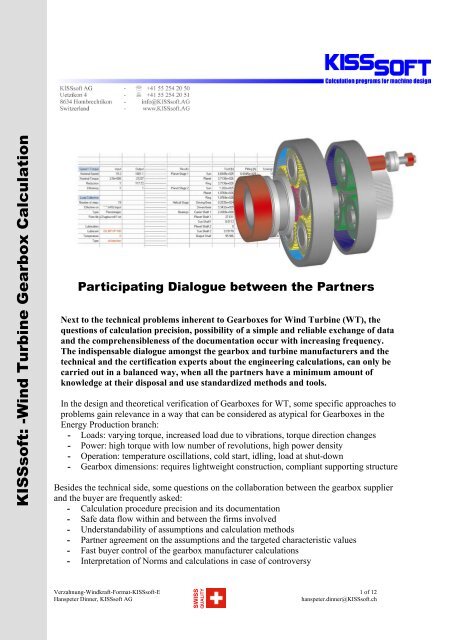
Participating Dialogue between the Partners<br />
Next to the technical problems inherent to <strong>Gearbox</strong>es for <strong>Wind</strong> <strong>Turbine</strong> (WT), the<br />
questions of calculation precision, possibility of a simple and reliable exchange of data<br />
and the comprehensibleness of the documentation occur with increasing frequency.<br />
The indispensable dialogue amongst the gearbox and turbine manufacturers and the<br />
technical and the certification experts about the engineering calculations, can only be<br />
carried out in a balanced way, when all the partners have a minimum amount of<br />
knowledge at their disposal and use standardized methods and tools.<br />
In the design and theoretical verification of <strong>Gearbox</strong>es for WT, some specific approaches to<br />
problems gain relevance in a way that can be considered as atypical for <strong>Gearbox</strong>es in the<br />
Energy Production branch:<br />
- Loads: varying torque, increased load due to vibrations, torque direction changes<br />
- Power: high torque with low number of revolutions, high power density<br />
- Operation: temperature oscillations, cold start, idling, load at shut-down<br />
- <strong>Gearbox</strong> dimensions: requires lightweight construction, compliant supporting structure<br />
Besides the technical side, some questions on the collaboration between the gearbox supplier<br />
and the buyer are frequently asked:<br />
- <strong>Calculation</strong> procedure precision and its documentation<br />
- Safe data flow within and between the firms involved<br />
- Understandability of assumptions and calculation methods<br />
- Partner agreement on the assumptions and the targeted characteristic values<br />
- Fast buyer control of the gearbox manufacturer calculations<br />
- Interpretation of Norms and calculations in case of controversy<br />
Verzahnung-<strong>Wind</strong>kraft-Format-<strong>KISSsoft</strong>-E 1 of 12<br />
Hanspeter Dinner, <strong>KISSsoft</strong> <strong>AG</strong><br />
hanspeter.dinner@<strong>KISSsoft</strong>.ch<br />
SWISS<br />
QUALITY
A gearbox calculation methodology that is manageable for both supplier and customer,<br />
presupposes, in the first place, a minimum of understanding, knowledge and experience on<br />
toothing theory, calculation and behaviour of WT in operation. The methodology must be<br />
applicable in a fast and secure way presupposing thus standardized tools, i.e., Software.<br />
Because of this, the calculation is now relatively less depending upon the inside know-how of<br />
the gearbox manufacturer and has to fulfill the gearbox customer demands for transparency.<br />
Furthermore, the Software must be usable for the whole procedure of layout, optimization,<br />
verification, documentation and study as, for instance, during revisions and/or training. Since<br />
this procedure spreads itself over several firms, the standardized Software may be used as a<br />
means of achieving a safe exchange of data.<br />
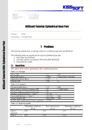
Qualified participating dialogueueue between<br />
Manufacturer / Customer / Certification expert<br />
Comprehensive calculation<br />
according to the Norms<br />
Comparison with several<br />
similar gearboxes<br />
Comparison of several<br />
different gearbox concepts;<br />
first sizing draft<br />
Quick and reliable<br />
layout /verification in<br />
view of getting a second<br />
opinion<br />
Know-how transfer,<br />
local content<br />
Standardized / comprehensible methodology, efficient tools, exchange of data<br />
Fig. 0-1 Use of a standardized <strong>Calculation</strong> Procedure<br />
Not all partners can afford the high costs involved with detailed analyses such as FEM (Finite<br />
Element Analysis) or vibration simulation. The idea behind this article is to describe, by<br />
means of an example of toothing calculation, how it is possible to get a qualified assessment<br />
about the toothing using user-friendly tools at a justifiable cost.<br />
1- <strong>Gearbox</strong> Concepts<br />
1.1 Current <strong>Gearbox</strong> Concepts<br />
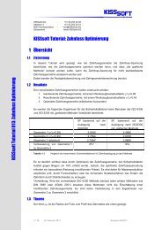
The following picture shows an overall view of the current gearbox concepts. At present, the<br />
standard is specially the one- and two-stage planetary gears (connected afterwards with two or<br />
one helical gear stages). An increase in power implying a larger number of gear-meshes<br />
results in a cost increase of the toothing calculation and further underlines it’s importance.<br />
Verzahnung-<strong>Wind</strong>kraft-Format-<strong>KISSsoft</strong>-E 2 of 12<br />
Hanspeter Dinner, <strong>KISSsoft</strong> <strong>AG</strong><br />
hanspeter.dinner@<strong>KISSsoft</strong>.ch<br />
SWISS<br />
QUALITY
Helical gear gearbox, also<br />
power-split<br />
One / two Planet stages<br />
Two / one Helical gear stages<br />
Planet stages<br />
With or without Helical gear<br />
stages<br />
(i. e. left: <strong>Wind</strong> <strong>Turbine</strong>/Renk,<br />
right: Multibrid/Renk)<br />
Also for power-split<br />
solutions with several<br />
generators<br />
Drive by the planet<br />
carrier<br />
PTO by the sun<br />
The ring is mostly in<br />
direct connection with<br />
the housing<br />
Helical helical gear<br />
stages<br />
Ring gear not part of<br />
the housing<br />
Favourable concerning<br />
bearing lubrication<br />
Internal load<br />
distribution to the<br />
stages<br />
Planet coupled gearbox<br />
(e.g. Left DPPV/MA<strong>AG</strong>)<br />
Ring gear not part of<br />
the housing<br />
Third stage as<br />
overlapped stage<br />
Planet differential gearbox<br />
(e. g. Bosch Rexroth,)<br />
Costly Construction<br />
Costly bearing<br />
Fig. 1-1 WTI <strong>Gearbox</strong> Concepts<br />
Verzahnung-<strong>Wind</strong>kraft-Format-<strong>KISSsoft</strong>-E 3 of 12<br />
Hanspeter Dinner, <strong>KISSsoft</strong> <strong>AG</strong><br />
hanspeter.dinner@<strong>KISSsoft</strong>.ch<br />
SWISS<br />
QUALITY
1.2 Trends<br />
Occasional peak loads will be decisive for determining the size of the <strong>Wind</strong> <strong>Turbine</strong> <strong>Gearbox</strong>.<br />
We will consider some concepts that limit the acting torques in the gearbox. We can consider<br />
here a planetary set as a differential gearbox superimposed to the fast running stage and with<br />
the support moment at the ring hydrostatically limited (Henderson <strong>Gearbox</strong>). More complex<br />
are some concepts that, through a CVT gearbox, also maintain a constant output speed as<br />
much as possible. These can be designed either as hydrodynamic (Voith Win Drive) or<br />
electrical additional drives.<br />
Other concepts go by that helical gear gearboxes must be used with multiple generators. The<br />
gearbox takes place through a central wheel, which meshes with the various pinions. The<br />
generators are either directly connected to the pinion shafts (e. g. Clipper Concept) or the<br />
power of several pinions is split over two generators using helical gear stages (e. g. Multi-<br />
Duored Concept).<br />
2 Gearing Verification of WTI <strong>Gearbox</strong>es<br />
2.1 Leading Verification Methods<br />
The gear verification is carried out according to the valid Norms and Directives currently in<br />
force. Following, we will assume that these calculation methods are known and will point out<br />
specific methods that deviate from the Norm and are meaningful for WT gearing.<br />
Tooth Root Strength<br />
As a rule, Norms underestimate the contact ratio influence, especially where it is typical to<br />
require a high precision manufacturing –WT <strong>Gearbox</strong>es. The following figures show the<br />
actual stress conditions (Flank – light blue; Root 1 – Violet; Root 2 – red) as compared to the<br />
results using the gear-mesh calculation according to DIN 3390. The tooth root stress is<br />
especially overestimated. Following figures show the comparison between the tooth root<br />
stress according to the Norm and the same stress taking into consideration the load<br />
distribution. Furthermore, this comparison clearly shows the influence of the pitch error on<br />
the stress conditions.<br />
Fig. 2-1 Influence of the Load Distribution over several Teeth on the Stress Levels. Left for Quality 7;<br />
Right for Quality 5. Final Stage of a 3.6 MW WTI ε α =1.73.<br />
Verzahnung-<strong>Wind</strong>kraft-Format-<strong>KISSsoft</strong>-E 4 of 12<br />
Hanspeter Dinner, <strong>KISSsoft</strong> <strong>AG</strong><br />
hanspeter.dinner@<strong>KISSsoft</strong>.ch<br />
SWISS<br />
QUALITY
Following modifications for the calculation of the ring gear strength are recommended:<br />
- <strong>Calculation</strong> at the 60º Tangent contact point taking into consideration the root contour<br />
actually produced by the tool as, for instance, suggested in the present revision (FDI)<br />
of the ISO 6336 (or the VDI 2737) (left figure below)<br />
- <strong>Calculation</strong> of the exact tooth profile based upon the generation simulation with the<br />
tool to calculate the YF and YS along the entire fillet (“graphical method”, right figure<br />
below)<br />
- Taking into consideration the ring gear’s wall thickness<br />
Comparing both figures shows that the calculation in accordance with the at the time valid<br />
DIN or ISO Norm versions strongly underestimates the ring gear strength.<br />
3<br />
2.5<br />
2<br />
1.5<br />
ISO6336 C<br />
ISO6336 B<br />
ISO6336 (erweitert) B<br />
Grafische Methode<br />
1.15<br />
1.1<br />
1.05<br />
1<br />
0.95<br />
ISO6336 (erweitert) B<br />
Grafische Methode<br />
1<br />
0.9<br />
0.5<br />
0.85<br />
0<br />
YF3 YS3 SF3<br />
0.8<br />
YF3 YFS3 SF3<br />
Fig. 2-2 Influence of the <strong>Calculation</strong> Methodology on the Ring Gear calculated Tooth Root Safety.<br />
Left: Reference Tooth Profile 1.25/0.38/1.00;<br />
Right: Reference Tooth Profile 1.40/0.38/1.25<br />
Tooth Flank Strength<br />
Because of the flank’s pressure charge, a shear stress distribution builds up in depth with a<br />
maximum under the surface. In case of overload, the increased shear stress results in cracks<br />
under the surface that lead to 0.5 to 1 mm material deterioration (pitting). During the case<br />
hardening of the flank, the hardening depth must exceed the one of the maximum shear stress<br />
peak depth. On the other hand, out of cost reasons, the case hardening depth must be as small<br />
as possible and that is where the shear stress distribution calculation that follows becomes<br />
interesting.<br />
Scuffing<br />
Fig. 2-3 Hertzian Stress Distribution inside the Toothing<br />
Verzahnung-<strong>Wind</strong>kraft-Format-<strong>KISSsoft</strong>-E 5 of 12<br />
Hanspeter Dinner, <strong>KISSsoft</strong> <strong>AG</strong><br />
hanspeter.dinner@<strong>KISSsoft</strong>.ch<br />
SWISS<br />
QUALITY
The ISO 6336 offers no solution for scuffing; it is usual here to use DIN 3990 Part 4. The<br />
<strong>AG</strong>MA 6006 as well as the GL guideline demand that the FZG lubricant scuffing load level<br />
for the calculation be reduced one unit. Nevertheless, because modern oils with EP (extreme<br />
pressure) additives have a scuffing load > 12 and the calculation methodology considers only<br />
maximum values of 12, this limitation is in practice less relevant. The calculation of the safety<br />
against scuffing is based upon an estimated temperature at the tooth line of contact, which<br />
depends upon the pressure and the sliding speed. Scuffing appears mainly on the tip and root<br />
areas where high relative speeds exist. In order to reduce the contact stress in these gear mesh<br />
areas, it is necessary to carry out tip- and/or root reliefs; the following figure shows their<br />
influence in the contact temperature.<br />
Fig. 2-4 Flash Temperature Reduction from 300 to 230 ºC because of Tip Relief. End Stage of a<br />
3.6 MW WTI. <strong>Calculation</strong> according to <strong>AG</strong>MA 925-A03.<br />
Micro pitting<br />
The friction between the tooth flanks due to insufficient lubrication, high load or unfavourable<br />
operational parameters, will also increase the friction due to tooth contact roughness (mixed<br />
friction µ=0.2-0.4 as opposed to viscose friction µ=0.05). Because of the higher friction<br />
stress, a shear stress develops at the tooth surface that can go beyond a critical value even at a<br />
still uncritical torque for creating pitting. This overstraining leads to material erosion at the<br />
surface (failure depth circa 10-20 µm over an area of about 20x100 µm) and to a grayish<br />
couloring of the tooth surface. The resulting profile error leads to a higher tooth stress (KHα,<br />
KFα, Kv, noise increases) and the risk of pitting also increases. A measure against the micro<br />
pitting risk is the specific lubricating film thickness λ, the quotient between the lubricating<br />
film thickness and the roughness of the toothing surface. The calculation is carried out in<br />
accordance with <strong>AG</strong>MA 925 or the FVA Work Sheets 54 / 259; there is also an ISO Norm in<br />
preparation.<br />
Fig. 2-5 λ-Values for the 1 st and 2 nd Planet Stages (Sun Planet Meshing Gear) and Helical Gear Stage for a<br />
3.6 MW WT <strong>Gearbox</strong><br />
Verzahnung-<strong>Wind</strong>kraft-Format-<strong>KISSsoft</strong>-E 6 of 12<br />
Hanspeter Dinner, <strong>KISSsoft</strong> <strong>AG</strong><br />
hanspeter.dinner@<strong>KISSsoft</strong>.ch<br />
SWISS<br />
QUALITY
Static Verification<br />
We must also carry out the static strength verification for toot plastic deformation or fracture.<br />
Since the classical static verification is not covered in the Norms, it is frequently considered<br />
as fatigue verification with a cycle factor = 1.<br />
However, verification for yield- and fracture limits is more meaningful.<br />
Required safety factors<br />
The required calculation safety factors are specified in the Norms. Determining the really<br />
required safety factors is extremely difficult and asks for a comprehensive field experience.<br />
The knowledge of these required safety factors constitute an enormous capital for the gearbox<br />
manufacturer because they can only be acquired not bought.<br />
Norm<br />
Verification in<br />
accordance to<br />
SF: (Fatigue /<br />
Static)<br />
SH: (Fatigue /<br />
Static)<br />
<strong>AG</strong>MA6006 <strong>AG</strong>MA2101-C95 1.0 1.0<br />
<strong>AG</strong>MA6006 ISO6336 1.56 1.25<br />
GL Norms ISO6336 1.5 (1.4) 1.2 (1.0)<br />
Danish WT Cert. Sch. ISO6336 1.45 1.2<br />
IEC61400 ISO6336 1.56 1.25<br />
2.2 Transmission Error, Meshing Shock<br />
The environment demands that WT have a low noise profile. The vibrations generated by the<br />
gearing are a considerable source of noise. Thus, the target must be, on one hand, to maintain<br />
the transmission error as low as possible and, on the other hand to reduce the meshing shock.<br />
This is why the layout of the tooth height and the tip relief (amount, type and height) is of<br />
utmost importance.<br />
Fig. 2-6 Line of Contact under Load. End Stage of a 3.6 MW WTI:<br />
Left: Premature Meshing in an uncorrected Toothing (Inflection in the Line of Contact).<br />
Center: Toothing with a shorter linear Tip Relief (6.2 µm and 0.5 µm).<br />
Right: Toothing with progressive Tip Relief (9.3 µm and 7.5 µm).<br />
On the left figure, the premature meshing (prolongation of the line of contact) leads to a socalled<br />
meshing shock that can be reduced by means of a tip relief and, afterwards, the line of<br />
contact will not show the characteristic prolongation anymore. However, for a linear relief,<br />
one can see this unstability in the line of contact (center figure) but this abrupt change in the<br />
angle of rotation can lead to vibrations. We can avoid this with a progressive relief (right<br />
figure).<br />
Verzahnung-<strong>Wind</strong>kraft-Format-<strong>KISSsoft</strong>-E 7 of 12<br />
Hanspeter Dinner, <strong>KISSsoft</strong> <strong>AG</strong><br />
hanspeter.dinner@<strong>KISSsoft</strong>.ch<br />
SWISS<br />
QUALITY
2.3 K Factors<br />
Application Factor K A<br />
For the gearing layout, a load spectrum can be easily replaced by a nominal load and an<br />
application factor K A . The calculation of K A can be done, e. g. in accordance to DIN 3990,<br />
Part 6, Method III or to <strong>AG</strong>MA 6006 as follows:<br />
T<br />
eq<br />
K<br />
A<br />
= ,<br />
Tn<br />
T<br />
eq<br />
⎛<br />
⎜<br />
= ⎜<br />
⎜<br />
⎝<br />
1/ p<br />
p<br />
∑ni<br />
* T ⎞<br />
i<br />
⎟<br />
p: Wöhler Line Slope, n<br />
i<br />
i : Load Change Stage i,<br />
∑<br />
i<br />
n<br />
i<br />
⎟<br />
⎟<br />
⎠<br />
T i : Torque in Stage i<br />
For a gear layout, the equivalent torque calculation with the derived K A , does not consider any<br />
horizontal part of the Wöhler line, being thus conservative. A finer procedure is for instance<br />
described in [2].<br />
Since the Wöhler line slope p changes for different materials, type of treatment as well as for<br />
root and flank, separate K A values (one for each p) must be determined. This is not very<br />
practical. That is why one should not use an application factor for the verification but a<br />
damage accumulation method (i. e. in accordance with DIN 3990, Part 6) for fatigue analysis.<br />
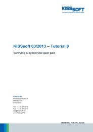
Load Distribution Factor<br />
Due to manufacturing tolerances and deformations, the load distribution between the load<br />
paths (Planets) is not equally balanced. Therefore, for the calculation of planetary sets the<br />
load has to be multiplied by a K γ factor. The data values for WT strongly differ according to<br />
each source, see Fig. 2-7, bellow. In order to improve the load distribution between the planet<br />
gears it is possible to equip independent planetary set elements (sun, ring, and planet) with<br />
elastic or floating bearings, for instance, floating sun shaft or elastic ring bearing. Another<br />
possibility is to use a flexible planet bearing (Flexpin, see [1]) as an elastic element. The<br />
Flexpin allows a planet radial or peripheral alignment. The effect of this flexible planet<br />
bearing can be seen in the chart bellow as a difference between the lines “MA<strong>AG</strong> without<br />
Flexpin” and MA<strong>AG</strong> with Flexpin” which are based partly on measurements, partly on<br />
experience. The Kγ values proposed by MA<strong>AG</strong> will be included in the new <strong>AG</strong>MA 6123.<br />
1.6<br />
1.5<br />
1.4<br />
GL<br />
DNV<br />
<strong>AG</strong>MA6123<br />
MA<strong>AG</strong> ohne Flexpin / <strong>AG</strong>MA6123, Appl. Level 3<br />
MA<strong>AG</strong> mit Flexpin / <strong>AG</strong>MA6123, Appl. Level 4<br />
IEC 61400<br />
K gamma [-]<br />
1.3<br />
1.2<br />
1.1<br />
1<br />
3 4 5 6 7 8<br />
Anzahl Planeten [-]<br />
Fig. 2-7 Load Distribution Factor in Function of the Number of Planets<br />
Verzahnung-<strong>Wind</strong>kraft-Format-<strong>KISSsoft</strong>-E 8 of 12<br />
Hanspeter Dinner, <strong>KISSsoft</strong> <strong>AG</strong><br />
hanspeter.dinner@<strong>KISSsoft</strong>.ch<br />
SWISS<br />
QUALITY
Measurements show that Kγ values sink with increasing loads because the manufacturing<br />
tolerances in comparison with the load-dependent deformations loose importance. However,<br />
they are costly and only allow conclusions for the product Kv*Kγ. The approximate values<br />
given above should only be taken as top limits. Because of this, since one can reach low Kγ<br />
values, solutions with more than three planets are anyway economical. For instance, with five<br />
planets and a measured Kγ=1.12, 95 % of the torque can be transmitted as well as for seven<br />
equally wide planets and a Kγ=1.50 (conservative assumption / regulations). This, again,<br />
allows higher stage ratios or offers more room for the layout of the planet carrier.<br />
Face Load Factor<br />
Face Load Factor K β describes the distribution of the peripheral load over the tooth width and<br />
its effect upon the flank- (K Hβ ) and root load (K Fβ ). Further to the simplified calculations as<br />
described in the Norms, the directives for WT <strong>Gearbox</strong>es ask for a detailed numerical<br />
calculation of the load distribution when a required minimal value (K β ≥1.15) should be<br />
reduced for the rating. For that, there are several calculation programs such as LVR, Rikor,<br />
Planlorr or LDP available.<br />
There is a way of achieving a uniform load on the tooth width with a toothing correction.<br />
Generally, the face load factor for thinner toothing is better than for a wider one. We mention<br />
here again the Flexpin because it prevents planet tilting under load (through K β directly<br />
reduced) and, by means of a favourable Kγ value, allows the use of five or seven thinner<br />
planets (with a lower K β ). These self-centering systems also allow using a still lower K β >1, critical:<br />
N∼1, overcritical: N>>1) that are defined by the reference speed N (pinion speed n 1 compared<br />
to the resonance speed n E1 ) where N considers the reduced toothing mass m red and the<br />
toothing rigidity c γ .<br />
Verzahnung-<strong>Wind</strong>kraft-Format-<strong>KISSsoft</strong>-E 9 of 12<br />
Hanspeter Dinner, <strong>KISSsoft</strong> <strong>AG</strong><br />
hanspeter.dinner@<strong>KISSsoft</strong>.ch<br />
SWISS<br />
QUALITY
N<br />
n1<br />
mred<br />
= = 2πn1<br />
z1<br />
, K v<br />
= f (N)<br />
n<br />
c<br />
E1<br />
γ<br />
Due to the low speed, WT will be operated in the sub critical zone and the Kv values will be<br />
correspondingly set. In the WT Certification Directives, as well as in the appropriate Norms, a<br />
value of Kv =1.05 or higher is requested. Should a lower value be used, measurements or a<br />
detailled calculation is required.<br />
2.4 <strong>Calculation</strong> with Load Spectra<br />
The toothing verification calculation is carried out with Load Spectra. These will be<br />
calculated determined from the wind speed charts for several wind mean speeds by means of<br />
dynamic simulation or from measurement time charts for torques and speeds at the rotor shaft.<br />
These time charts will then be classified by speed and torque in a load duration distribution<br />
spectra. We have to stress that, the speed practically does not vary and that it enters the<br />
service life calculation in a linear way. The classification should thus orient itself in direction<br />
of the torque chart.<br />
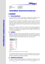
There is a question whether K factors, especially K β , should remain fixed for every load stage<br />
(for instance as requested in [2] / [3]) or be separately calculated for each load stage<br />
(according to [8]). The following comparison (see also [11]) shows that, however, the<br />
calculated toothing safety factors only slightly differ from each other when instead of a<br />
constant K Hβ =1.26 (calculated for the nominal load) they are separately calculated for each<br />
load stage.<br />
1.8<br />
1.27<br />
1.7<br />
1.6<br />
1.5<br />
1.681<br />
1.644<br />
1.651<br />
1.618<br />
Rad 1, Khb variabel<br />
Rad 1, Khb konstant<br />
Rad 2, Khb variabel<br />
Rad 2, Khb konstant<br />
Khbeta [-]<br />
1.26<br />
1.25<br />
1.24<br />
1.23<br />
1.4<br />
1.384<br />
1.363<br />
1.22<br />
Khb variabel<br />
Khb konstant<br />
1.3<br />
1.2<br />
SF<br />
1.269<br />
1.251<br />
SH<br />
Fig. 2-8 Comparison between <strong>Calculation</strong>s with variable and constant K β .<br />
End Stage of a 3.6 MW WTI, L=20.000 h, ISO 6336, B.<br />
1.21<br />
1.2<br />
1 3 5 7 9 11 13 15 17<br />
Lastschritt [-]<br />
Frequently, it can be observed that only a few steps in the load spectra generate the majority<br />
of partial damage. It is then meaningful to further subdivide and identify these relevant<br />
damaging load levels. Often, it is here the question of the influence of load levels with very<br />
high loads (close to the static strength) but with a low cycle numbers (low cycle fatigue).<br />
DIN and ISO also likely underestimate the influence of load bins with high cycle umbers but<br />
lower loads (high cycle fatigue). While using DIN 3990 and ISO 6336, it is thus meaningful,<br />
to modify the Wöhler line with the Haibach modification (no fatigue limit zone, see Line b) in<br />
the left part of the figure bellow) and recalculate in order to determine a lower conservative<br />
limit.<br />
Verzahnung-<strong>Wind</strong>kraft-Format-<strong>KISSsoft</strong>-E 10 of 12<br />
Hanspeter Dinner, <strong>KISSsoft</strong> <strong>AG</strong><br />
hanspeter.dinner@<strong>KISSsoft</strong>.ch<br />
SWISS<br />
QUALITY
3<br />
2.5<br />
2<br />
2.39<br />
2.306<br />
1.996 2.01<br />
Nicht mofiziert<br />
Haibach modifiziert<br />
1.5<br />
1.353 1.393<br />
1.274 1.338<br />
1<br />
0.5<br />
0<br />
SF1 SF2 SH1 SH2<br />
Fig. 2-9 Haibach Modification Influence in the calculated Safety Factors; not “modified”<br />
according to Line a); “Haibach modified” according to Line b)<br />
3 Summary<br />
3.1 Investment in Fundamentals<br />
In view of the background of the often-occurring damages in WT <strong>Gearbox</strong>es, it is of vital<br />
interest for all participants to maintain a qualified and balanced dialogue. An aspect of this<br />
dialogue is the calculation of the verification of the toothing strength that was shown in this<br />
article. Here, it is necessary to invest in education and training, tools and procedures in order<br />
to balance the information gradient between gearbox manufacturers and customers.<br />
3.2 <strong>Calculation</strong> Procedure Safety<br />
The administration of many individual calculations, the use of different tools und the<br />
necessity to use identical data in the engineering analysis, drawing an fabrication leads to a<br />
highly tiresome task in the management of data. The target should thus be to manage with the<br />
appropriate tools all WT necessary gearbox calculations (toothing, bearings, shafts, joints)<br />
integrating them in a comprehensive model. This will also allow for the fast verification of the<br />
complete gearbox for changed input data, e. g. customer-specific load spectra as well as back<br />
tracing of field experience according to the spirit of Know-how management. The integration<br />
of all engineering analysis data into a single dataset can also be achieved with respective<br />
software.<br />
3.3 Questions on the appropriate <strong>Gearbox</strong> Concept<br />
At present, there is no comparison of the gearbox concepts mentioned above concerning<br />
calculation verification, construction details, production, costs and operational behaviour<br />
available and they must be internally prepared inside the Firm. They will constitute the basis<br />
for a Risk Estimation before Investment Decisions. For the buyer of gearboxs, it must be<br />
rather interesting to have a supplier-independent standardized methodology, with the<br />
corresponding tools, allowing him to compare in a fast and safe way different gearbox<br />
concepts or gearboxs from different suppliers.<br />
Verzahnung-<strong>Wind</strong>kraft-Format-<strong>KISSsoft</strong>-E 11 of 12<br />
Hanspeter Dinner, <strong>KISSsoft</strong> <strong>AG</strong><br />
hanspeter.dinner@<strong>KISSsoft</strong>.ch<br />
SWISS<br />
QUALITY
1 Bibliography<br />
[1] U. Giger, G.P. Fox, Leistungsverzweigte Planetengetriebe in <strong>Wind</strong>energieanlagen mit<br />
flexibler Planetenlagerung, ATK03<br />
[2] <strong>AG</strong>MA6006-A03, Standard for Design and Specification of <strong>Gearbox</strong>es for <strong>Wind</strong><br />
<strong>Turbine</strong>s, 2003<br />
[3] ISO81400-4, <strong>Wind</strong> turbines, Design and Specification of gearboxes, 2005<br />
[4] <strong>AG</strong>MA6123-A88, Design Manual for Enclosed Epicyclic Metric Module Gear Drives,<br />
1988<br />
[5] <strong>AG</strong>MA6123-BXX, Design Manual for Enclosed Epicyclic Gear Drives, Draft, 2004<br />
[6] Germanischer Lloyd, Richtlinie für die Zertifizierung von <strong>Wind</strong>energieanlagen,<br />
2003/2004<br />
[7] Det Norske Veritas, Guidelines for Design of <strong>Wind</strong> <strong>Turbine</strong>s<br />
[8] The Danish Energy Authority, Recommendation to Comply with the Technical<br />
Criteria of the Danish <strong>Wind</strong> <strong>Turbine</strong> Certification Scheme, 2005<br />
[9] IEC 61400, Design Requirements for <strong>Wind</strong> <strong>Turbine</strong> <strong>Gearbox</strong>es, Draft, 2005<br />
[10] VDI2737, Berechnung der Zahnfusstragfähigkeit von Innenverzahnungen mit<br />
Zahnkranzeinfluss, 2003<br />
[11] R. Grzybowski, B. Niederstucke, Betriebsfestigkeitsberechnung von Getrieben<br />
in <strong>Wind</strong>energieanlagen mit Veweildauerkollektiven, AZT Expertentage 2004<br />
Verzahnung-<strong>Wind</strong>kraft-Format-<strong>KISSsoft</strong>-E 12 of 12<br />
Hanspeter Dinner, <strong>KISSsoft</strong> <strong>AG</strong><br />
hanspeter.dinner@<strong>KISSsoft</strong>.ch<br />
SWISS<br />
QUALITY