

Intel PXA250 and PXA210 Applications Processors
Intel PXA250 and PXA210 Applications Processors
Intel PXA250 and PXA210 Applications Processors

Create successful ePaper yourself
Turn your PDF publications into a flip-book with our unique Google optimized e-Paper software.
Introduction<br />
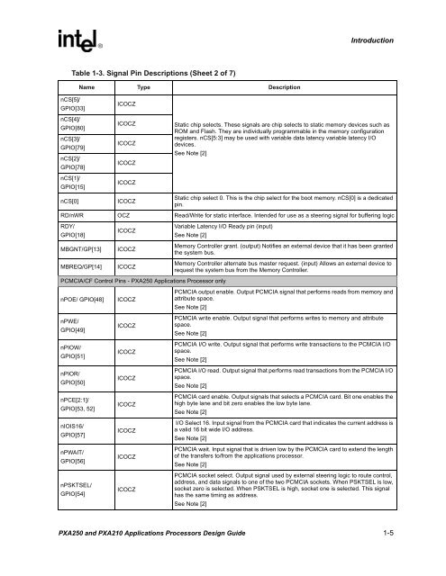
Table 1-3. Signal Pin Descriptions (Sheet 2 of 7)<br />
Name Type Description<br />
nCS[5]/<br />
GPIO[33]<br />
nCS[4]/<br />
GPIO[80]<br />
nCS[3]/<br />
GPIO[79]<br />
nCS[2]/<br />
GPIO[78]<br />
nCS[1]/<br />
GPIO[15]<br />
nCS[0]<br />
ICOCZ<br />
ICOCZ<br />
ICOCZ<br />
ICOCZ<br />
ICOCZ<br />
ICOCZ<br />
Static chip selects. These signals are chip selects to static memory devices such as<br />
ROM <strong>and</strong> Flash. They are individually programmable in the memory configuration<br />
registers. nCS[5:3] may be used with variable data latency variable latency I/O<br />
devices.<br />
See Note [2]<br />
Static chip select 0. This is the chip select for the boot memory. nCS[0] is a dedicated<br />
pin.<br />
RD/nWR OCZ Read/Write for static interface. Intended for use as a steering signal for buffering logic<br />
RDY/<br />
GPIO[18]<br />
MBGNT/GP[13]<br />
MBREQ/GP[14]<br />
ICOCZ<br />
ICOCZ<br />
ICOCZ<br />
Variable Latency I/O Ready pin (input)<br />
See Note [2]<br />
Memory Controller grant. (output) Notifies an external device that it has been granted<br />
the system bus.<br />
Memory Controller alternate bus master request. (input) Allows an external device to<br />
request the system bus from the Memory Controller.<br />
PCMCIA/CF Control Pins - <strong>PXA250</strong> <strong>Applications</strong> Processor only<br />
nPOE/ GPIO[48]<br />
nPWE/<br />
GPIO[49]<br />
nPIOW/<br />
GPIO[51]<br />
nPIOR/<br />
GPIO[50]<br />
nPCE[2:1]/<br />
GPIO[53, 52]<br />
nIOIS16/<br />
GPIO[57]<br />
nPWAIT/<br />
GPIO[56]<br />
nPSKTSEL/<br />
GPIO[54]<br />
ICOCZ<br />
ICOCZ<br />
ICOCZ<br />
ICOCZ<br />
ICOCZ<br />
ICOCZ<br />
ICOCZ<br />
ICOCZ<br />
PCMCIA output enable. Output PCMCIA signal that performs reads from memory <strong>and</strong><br />
attribute space.<br />
See Note [2]<br />
PCMCIA write enable. Output signal that performs writes to memory <strong>and</strong> attribute<br />
space.<br />
See Note [2]<br />
PCMCIA I/O write. Output signal that performs write transactions to the PCMCIA I/O<br />
space.<br />
See Note [2]<br />
PCMCIA I/O read. Output signal that performs read transactions from the PCMCIA I/O<br />
space.<br />
See Note [2]<br />
PCMCIA card enable. Output signals that selects a PCMCIA card. Bit one enables the<br />
high byte lane <strong>and</strong> bit zero enables the low byte lane.<br />
See Note [2]<br />
I/O Select 16. Input signal from the PCMCIA card that indicates the current address is<br />
a valid 16 bit wide I/O address.<br />
See Note [2]<br />
PCMCIA wait. Input signal that is driven low by the PCMCIA card to extend the length<br />
of the transfers to/from the applications processor.<br />
See Note [2]<br />
PCMCIA socket select. Output signal used by external steering logic to route control,<br />
address, <strong>and</strong> data signals to one of the two PCMCIA sockets. When PSKTSEL is low,<br />
socket zero is selected. When PSKTSEL is high, socket one is selected. This signal<br />
has the same timing as address.<br />
See Note [2]<br />
<strong>PXA250</strong> <strong>and</strong> <strong>PXA210</strong> <strong>Applications</strong> <strong>Processors</strong> Design Guide 1-5


