


You also want an ePaper? Increase the reach of your titles
YUMPU automatically turns print PDFs into web optimized ePapers that Google loves.
19-1572; Rev 0; 12/99<br />
Low-Cost, +5V, <strong>Serial</strong>-Input,<br />
Voltage-Output, <strong>16</strong>-Bit <strong>DAC</strong><br />
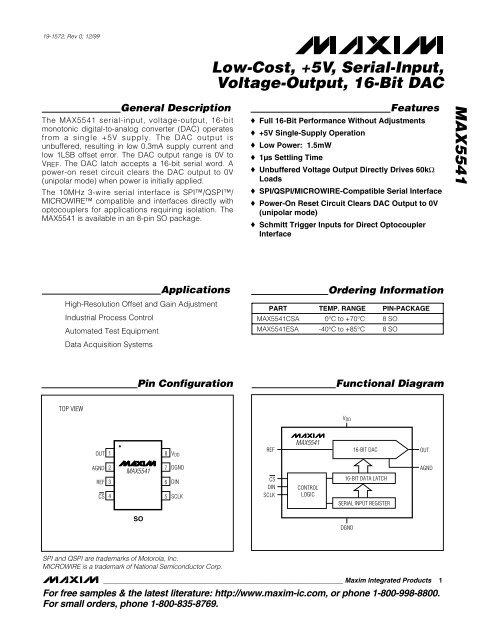
General Description<br />
The MAX5541 serial-input, voltage-output, <strong>16</strong>-<strong>bit</strong><br />
monotonic digital-to-analog converter (<strong>DAC</strong>) operates<br />
from a single +5V supply. The <strong>DAC</strong> output is<br />
unbuffered, resulting in low 0.3mA supply current and<br />
low 1LSB offset error. The <strong>DAC</strong> output range is 0V to<br />
V REF . The <strong>DAC</strong> latch accepts a <strong>16</strong>-<strong>bit</strong> serial word. A<br />
power-on reset circuit clears the <strong>DAC</strong> output to 0V<br />
(unipolar mode) when power is initially applied.<br />
The 10MHz 3-wire serial interface is SPI/QSPI/<br />
MICROWIRE compatible and interfaces directly with<br />
optocouplers for applications requiring isolation. The<br />
MAX5541 is available in an 8-pin SO package.<br />
Features<br />
♦ Full <strong>16</strong>-Bit Performance Without Adjustments<br />
♦ +5V Single-Supply Operation<br />
♦ Low Power: 1.5mW<br />
♦ 1µs Settling Time<br />
♦ Unbuffered Voltage Output Directly Drives 60kΩ<br />
Loads<br />
♦ SPI/QSPI/MICROWIRE-Compatible <strong>Serial</strong> Interface<br />
♦ Power-On Reset Circuit Clears <strong>DAC</strong> Output to 0V<br />
(unipolar mode)<br />
♦ Schmitt Trigger Inputs for Direct Optocoupler<br />
Interface<br />
MAX5541<br />
Applications<br />
High-Resolution Offset and Gain Adjustment<br />
Industrial Process Control<br />
Automated Test Equipment<br />
Data Acquisition Systems<br />
PART<br />
MAX5541CSA<br />
MAX5541ESA<br />
Ordering Information<br />
TEMP. RANGE PIN-PACKAGE<br />
0°C to +70°C 8 SO<br />
-40°C to +85°C 8 SO<br />
Pin Configuration<br />
Functional Diagram<br />
TOP VIEW<br />
V DD<br />
OUT<br />
1<br />
8<br />
V DD<br />
REF<br />
MAX5541<br />
<strong>16</strong>-BIT <strong>DAC</strong><br />
OUT<br />
AGND<br />
REF<br />
CS<br />
2<br />
3<br />
4<br />
MAX5541<br />
7<br />
6<br />
5<br />
DGND<br />
DIN<br />
SCLK<br />
CS<br />
DIN<br />
SCLK<br />
CONTROL<br />
LOGIC<br />
<strong>16</strong>-BIT DATA LATCH<br />
SERIAL INPUT REGISTER<br />
AGND<br />
SO<br />
DGND<br />
SPI and QSPI are trademarks of Motorola, Inc.<br />
MICROWIRE is a trademark of National Semiconductor Corp.<br />
________________________________________________________________ Maxim Integrated Products 1<br />
For free samples & the latest literature: http://www.maxim-ic.com, or phone 1-800-998-8800.<br />
For small orders, phone 1-800-835-8769.
Low-Cost, +5V, <strong>Serial</strong>-Input,<br />
Voltage-Output, <strong>16</strong>-Bit <strong>DAC</strong><br />
MAX5541<br />
ABSOLUTE MAXIMUM RATINGS<br />
V DD to DGND............................................................-0.3V to +6V<br />
CS, SCLK, DIN to DGND..........................................-0.3V to +6V<br />
REF to AGND, DGND..................................-0.3V to (V DD +0.3V)<br />
AGND to DGND.....................................................-0.3V to +0.3V<br />
OUT to AGND, DGND.................................. ............-0.3V to V DD<br />
Maximum Current into Any Pin............................................50mA<br />
Continuous Power Dissipation (T A = +70°C)<br />
8-Pin SO (derate 5.88mW/°C above +70°C)................471mW<br />
Operating Temperature Ranges<br />
MAX5541CSA .....................................................0°C to +70°C<br />
MAX5541ESA ..................................................-40°C to +85°C<br />
Junction Temperature......................................................+150°C<br />
Storage Temperature Range .............................-65°C to +150°C<br />
Lead Temperature (soldering, 10sec) ............................ +300°C<br />
Stresses beyond those listed under “Absolute Maximum Ratings” may cause permanent damage to the device. These are stress ratings only, and functional<br />
operation of the device at these or any other conditions beyond those indicated in the operational sections of the specifications is not implied. Exposure to<br />
absolute maximum rating conditions for extended periods may affect device reliability.<br />
ELECTRICAL CHARACTERISTICS<br />
(V DD = +5V ±5%, V REF = +2.5V, V AGND = V DGND = 0, T A = T MIN to T MAX , unless otherwise noted. Typical values are at T A = +25°C.)<br />
Resolution<br />
PARAMETER<br />
Gain-Error Tempco<br />
<strong>DAC</strong> Output Resistance<br />
Power-Supply Rejection<br />
REFERENCE INPUT<br />
Reference Input Range<br />
Reference Input Resistance<br />
(Note 4)<br />
N<br />
R OUT<br />
PSR<br />
V REF<br />
R REF<br />
T A = +25°C<br />
T A = T MIN to T MAX<br />
T A = T MIN to T MAX<br />
T A = +25°C<br />
T A = T MIN to T MAX<br />
(Note 2)<br />
4.75V ≤ V DD ≤ 5.25V<br />
(Note 3)<br />
CONDITIONS<br />
Integral Nonlinearity INL V DD = 5V<br />
±4 ±<strong>16</strong><br />
Zero-Code Offset Error<br />
Zero-Code Tempco<br />
Gain Error (Note 1)<br />
SYMBOL<br />
STATIC PERFORMANCE—ANALOG SECTION (R L = ∞)<br />
Differential Nonlinearity<br />
Output Settling Time<br />
DNL<br />
ZSE<br />
ZS TC<br />
Guaranteed monotonic<br />
DYNAMIC PERFORMANCE—ANALOG SECTION (R L = ∞)<br />
Voltage-Output Slew Rate<br />
SR<br />
MIN TYP MAX<br />
<strong>16</strong><br />
2.0 3.0<br />
11.5<br />
±0.5 ±1.0<br />
±0.05<br />
±0.1<br />
6.25<br />
±1<br />
±2<br />
±5<br />
±10<br />
±1.0<br />
UNITS<br />
Bits<br />
LSB<br />
LSB<br />
ppm/°C<br />
LSB<br />
ppm/°C<br />
kΩ<br />
LSB<br />
C L = 10pF (Note 5) 25 V/µs<br />
To ± 1 /2LSB of FS, C L = 10pF 1 µs<br />
Bits<br />
V<br />
kΩ<br />
2 _______________________________________________________________________________________
Low-Cost, +5V, <strong>Serial</strong>-Input,<br />
Voltage-Output, <strong>16</strong>-Bit <strong>DAC</strong><br />
ELECTRICAL CHARACTERISTICS (continued)<br />
(V DD = +5V ±5%, V REF = +2.5V, V AGND = V DGND = 0, T A = T MIN to T MAX , unless otherwise noted. Typical values are at T A = +25°C.)<br />
PARAMETER<br />
<strong>DAC</strong> Glitch Impulse<br />
SYMBOL<br />
CONDITIONS<br />
Major-carry transition<br />
Digital Feedthrough<br />
Code = 0000 hex, CS = V DD ,<br />
SCLK = V DIN = 0 to V DD levels<br />
DYNAMIC PERFORMANCE—REFERENCE SECTION<br />
Reference -3dB Bandwidth BW Code = FFFF hex<br />
Reference Feedthrough<br />
Code = 0000 hex, V REF = 1Vp-p at 100kHz<br />
Signal-to-Noise Ratio<br />
SNR<br />
Reference Input Capacitance C IN<br />
Code = 0000 hex<br />
Code = FFFF hex<br />
STATIC PERFORMANCE—DIGITAL INPUTS<br />
Input High Voltage<br />
V IH<br />
Input Low Voltage<br />
V IL<br />
Input Current<br />
I IN V IN = 0<br />
Input Capacitance<br />
C IN (Note 6)<br />
Hysteresis Voltage<br />
V H<br />
POWER SUPPLY<br />
Positive Supply Range<br />
V DD<br />
Positive Supply Current<br />
I DD<br />
Power Dissipation<br />
PD<br />
MIN TYP MAX<br />
10<br />
2.4<br />
10<br />
1<br />
1<br />
92<br />
75<br />
120<br />
0.40<br />
0.8<br />
±1<br />
10<br />
4.75 5.25<br />
0.3 1.1<br />
1.5<br />
UNITS<br />
nVs<br />
nVs<br />
MHz<br />
mVp-p<br />
dB<br />
pF<br />
V<br />
V<br />
µA<br />
pF<br />
V<br />
V<br />
mA<br />
mW<br />
MAX5541<br />
TIMING CHARACTERISTICS<br />
(V DD = +5V ±5%, V REF = +2.5V, V AGND = V DGND = 0, CMOS inputs, T A = T MIN to T MAX , unless otherwise noted.)<br />
PARAMETER<br />
SYMBOL<br />
CONDITIONS<br />
MIN TYP MAX<br />
UNITS<br />
SCLK Frequency<br />
f CLK<br />
10<br />
MHz<br />
SCLK Pulse Width High<br />
t CH<br />
45<br />
ns<br />
SCLK Pulse Width Low<br />
t CL<br />
45<br />
ns<br />
CS Low to SCLK High Setup<br />
t CSS0<br />
45<br />
ns<br />
CS High to SCLK High Setup<br />
t CSS1<br />
45<br />
ns<br />
SCLK High to CS Low Hold<br />
t CSH0<br />
(Note 6)<br />
30<br />
ns<br />
SCLK High to CS High Hold<br />
t CSH1<br />
45<br />
ns<br />
DIN to SCLK High Setup<br />
t DS<br />
40<br />
ns<br />
DIN to SCLK High Hold<br />
t DH<br />
0<br />
ns<br />
V DD High to CS Low<br />
(power-up delay)<br />
20<br />
µs<br />
Note 1: Gain Error tested at V REF = +2.0V, +2.5V, and +3.0V.<br />
Note 2: R OUT tolerance is typically ±20%.<br />
Note 3: Min/Max ranges guaranteed by gain-error test. Operation outside min/max limits will result in degraded performance.<br />
Note 4: Reference input resistance is code dependent, minimum at 8555 hex.<br />
Note 5: Slew-rate value is measured from 0% to 63%.<br />
Note 6: Guaranteed by design. Not production tested.<br />
_______________________________________________________________________________________ 3
Low-Cost, +5V, <strong>Serial</strong>-Input,<br />
Voltage-Output, <strong>16</strong>-Bit <strong>DAC</strong><br />
MAX5541<br />
(V DD = +5V, V REF = +2.5V, T A = +25°C, unless otherwise noted.)<br />
SUPPLY CURRENT (mA)<br />
0.50<br />
0.45<br />
0.40<br />
0.35<br />
0.30<br />
0.25<br />
SUPPLY CURRENT<br />
vs. TEMPERATURE<br />
0.20<br />
-40 -20 0 20 40 60 80 100<br />
TEMPERATURE (°C)<br />
MAX5541-01<br />
SUPPLY CURRENT (mA)<br />
0.35<br />
0.34<br />
0.33<br />
0.32<br />
0.31<br />
0.30<br />
0.29<br />
SUPPLY CURRENT<br />
vs. REFERENCE VOLTAGE<br />
0.28<br />
0 1 2 3 4 5 6<br />
REFERENCE VOLTAGE (V)<br />
Typical Operating Characteristics<br />
MAX5541-02<br />
ZERO-CODE OFFSET ERROR (LSB)<br />
1.0<br />
0.8<br />
0.6<br />
0.4<br />
0.2<br />
0<br />
-0.2<br />
-0.4<br />
-0.6<br />
ZERO-CODE OFFSET ERROR<br />
vs. TEMPERATURE<br />
-0.8<br />
-1.0<br />
-60 -20 20 60 100 140<br />
TEMPERATURE (°C)<br />
MAX5541-03<br />
1.0<br />
0.8<br />
INTEGRAL NONLINEARITY<br />
vs. TEMPERATURE<br />
MAX5541-04<br />
1.0<br />
0.8<br />
DIFFERENTIAL NONLINEARITY<br />
vs. TEMPERATURE<br />
MAX5541-05<br />
1.0<br />
0.8<br />
GAIN ERROR<br />
vs. TEMPERATURE<br />
MAX5541-06<br />
0.6<br />
0.6<br />
0.6<br />
INL (LSB)<br />
0.4<br />
0.2<br />
0<br />
-0.2<br />
-0.4<br />
-0.6<br />
-INL<br />
+INL<br />
DNL (LSB)<br />
0.4<br />
0.2<br />
0<br />
-0.2<br />
-0.4<br />
-0.6<br />
-DNL<br />
+DNL<br />
GAIN ERROR (LSB)<br />
0.4<br />
0.2<br />
0<br />
-0.2<br />
-0.4<br />
-0.6<br />
-0.8<br />
-0.8<br />
-0.8<br />
-1.0<br />
-60 -20 20 60 100 140<br />
-1.0<br />
-60 -20 20 60 100 140<br />
-1.0<br />
-60 -20 20 60 100 140<br />
TEMPERATURE (°C)<br />
TEMPERATURE (°C)<br />
TEMPERATURE (°C)<br />
INL (LSB)<br />
1.00<br />
0.75<br />
0.50<br />
0.25<br />
0<br />
-0.25<br />
-0.50<br />
-0.75<br />
INTEGRAL NONLINEARITY<br />
vs. CODE<br />
MAX5541-07<br />
DNL (LSB)<br />
1.00<br />
0.75<br />
0.50<br />
0.25<br />
0<br />
-0.25<br />
-0.50<br />
-0.75<br />
DIFFERENTIAL NONLINEARITY<br />
vs. CODE<br />
MAX5541-08<br />
REFERENCE CURRENT (µA)<br />
200<br />
<strong>16</strong>0<br />
120<br />
80<br />
40<br />
REFERENCE CURRENT<br />
vs. CODE<br />
MAX5541-09<br />
-1.00<br />
0 10k 20k 30k 40k 50k 60k 70k<br />
-1.00<br />
0 10k 20k 30k 40k 50k 60k 70k<br />
0<br />
0 10k 20k 30k 40k 50k 60k 70k<br />
<strong>DAC</strong> CODE<br />
<strong>DAC</strong> CODE<br />
<strong>DAC</strong> CODE<br />
4 _______________________________________________________________________________________
Low-Cost, +5V, <strong>Serial</strong>-Input,<br />
Voltage-Output, <strong>16</strong>-Bit <strong>DAC</strong><br />
Typical Operating Characteristics (continued)<br />
(V DD = +5V, V REF = +2.5V, T A = +25°C, unless otherwise noted.)<br />
FULL-SCALE STEP RESPONSE<br />
(f SCLK = 10MHz)<br />
MAX5541-10<br />
FULL-SCALE STEP RESPONSE<br />
(f SCLK = 20MHz)<br />
MAX5541-11<br />
MAX5541<br />
OUT<br />
500mV/div<br />
OUT<br />
500mV/div<br />
C L = 13pF, R L = ∞<br />
1µs/div<br />
C L = 13pF, R L = ∞<br />
400ns/div<br />
MAJOR-CARRY OUTPUT GLITCH<br />
DIGITAL FEEDTHROUGH<br />
MAX5541-12<br />
MAX5541-13<br />
CS<br />
5V/div<br />
SCLK<br />
5V/div<br />
OUT<br />
AC-COUPLED<br />
100mV/div<br />
OUT<br />
AC-COUPLED<br />
50mV/div<br />
2µs/div<br />
CODE = 0000 hex<br />
2µs/div<br />
______________________________________________________________Pin Description<br />
PIN<br />
1<br />
2<br />
3<br />
4<br />
5<br />
6<br />
7<br />
8<br />
NAME<br />
OUT<br />
AGND<br />
REF<br />
CS<br />
SCLK<br />
DIN<br />
DGND<br />
V DD<br />
FUNCTION<br />
<strong>DAC</strong> Output Voltage<br />
Analog Ground<br />
Voltage Reference Input. Connect to external +2.5V reference.<br />
Chip-Select Input<br />
<strong>Serial</strong>-Clock Input. Duty cycle must be between 40% and 60%.<br />
<strong>Serial</strong>-Data Input<br />
Digital Ground<br />
+5V Supply Voltage<br />
_______________________________________________________________________________________ 5
Low-Cost, +5V, <strong>Serial</strong>-Input,<br />
Voltage-Output, <strong>16</strong>-Bit <strong>DAC</strong><br />
MAX5541<br />
Detailed Description<br />
The MAX5541 voltage-output, <strong>16</strong>-<strong>bit</strong> digital-to-analog<br />
converter (<strong>DAC</strong>) offers <strong>16</strong>-<strong>bit</strong> monotonicity with less<br />
than 1LSB differential linearity error. <strong>Serial</strong>-data transfer<br />
minimizes the number of package pins required.<br />
The MAX5541 is composed of two matched <strong>DAC</strong> sections,<br />
with a 12-<strong>bit</strong> inverted R-2R <strong>DAC</strong> forming the 12<br />
LSBs and the 4 MSBs derived from 15 identically<br />
matched resistors. This architecture allows the lowest<br />
glitch energy to be transferred to the <strong>DAC</strong> output on<br />
major-carry transitions. It also decreases the <strong>DAC</strong> output<br />
impedance by a factor of eight compared to a standard<br />
R-2R ladder, allowing unbuffered operation in<br />
medium-load applications. Figure 1 is the Timing<br />
Diagram.<br />
Digital Interface<br />
The MAX5541 digital interface is a standard 3-wire connection<br />
compatible with SPI/QSPI/MICROWIRE interfaces.<br />
The chip-select input (CS) frames the serial data<br />
loading at the data input pin (DIN). Immediately following<br />
CS’s high-to-low transition, the data is shifted<br />
synchronously and latched into the input register on the<br />
rising edge of the serial-clock input (SCLK). After <strong>16</strong><br />
data <strong>bit</strong>s have been loaded into the serial input register,<br />
it transfers its contents to the <strong>DAC</strong> latch on CS’s<br />
low-to-high transition (Figure 2). Note that if CS does<br />
not remain low during the entire <strong>16</strong> SCLK cycles, data<br />
will be corrupted. In this case, reload the <strong>DAC</strong> latch<br />
with a new <strong>16</strong>-<strong>bit</strong> word.<br />
External Reference<br />
The MAX5541 operates with external voltage references<br />
from 2V to 3V. The reference voltage determines<br />
the <strong>DAC</strong>’s full-scale output voltage.<br />
Power-On Reset<br />
The MAX5541 has a power-on reset circuit to set the<br />
<strong>DAC</strong>’s output to 0V in unipolar mode when V DD is first<br />
applied. This ensures that unwanted <strong>DAC</strong> output voltages<br />
will not occur immediately following a system<br />
power-up, such as after power loss. In bipolar mode,<br />
the <strong>DAC</strong> output is set to -V REF .<br />
CS<br />
t CSH1<br />
t CSS1<br />
t CSHO<br />
t CSSO<br />
t CH<br />
t CL<br />
SCLK<br />
;;;;;;;;;<br />
t DS<br />
t DH<br />
DIN D15 D14 D0<br />
Figure 1. Timing Diagram<br />
CS<br />
SCLK<br />
<strong>DAC</strong><br />
UPDATED<br />
; ; ;;<br />
DIN<br />
D15 D14 D13 D12 D11 D10 D9 D8 D7 D6 D5 D4 D3 D2 D1 D0<br />
MSB<br />
Figure 2. 3-Wire Interface Timing Diagram<br />
LSB<br />
6 _______________________________________________________________________________________
Low-Cost, +5V, <strong>Serial</strong>-Input,<br />
Voltage-Output, <strong>16</strong>-Bit <strong>DAC</strong><br />
Applications Information<br />
Reference and Analog Ground Inputs<br />
The MAX5541 operates with external voltage references<br />
from 2V to 3V, and maintains <strong>16</strong>-<strong>bit</strong> performance with<br />
proper reference selection and application. Ideally, the<br />
reference’s temperature coefficient should be less than<br />
0.4ppm/°C to maintain <strong>16</strong>-<strong>bit</strong> accuracy to within 1LSB<br />
over the commercial (0°C to +70°C) temperature range.<br />
Since this converter is designed as an inverted R-2R<br />
voltage-mode <strong>DAC</strong>, the input resistance seen by the<br />
voltage reference is code dependent. The worst-case<br />
input-resistance variation is from 11.5kΩ (at code 8555<br />
hex) to 200kΩ (at code 0000 hex). The maximum<br />
change in load current for a 2.5V reference is 2.5V/<br />
11.5kΩ = 217µA; therefore, the required load regulation<br />
is 7ppm/mA for a maximum error of 0.1LSB. This implies<br />
a reference output impedance of 60kΩ) without degradation of INL or DNL; only<br />
the gain error is increased by externally loading the<br />
<strong>DAC</strong> output.<br />
External Output Buffer Amplifier<br />
In unipolar mode, the output amplifier is used in a voltage-follower<br />
connection. The <strong>DAC</strong>’s output resistance<br />
is constant and is independent of input code; however,<br />
the output amplifier’s input impedance should still be as<br />
high as possible to minimize gain errors. The <strong>DAC</strong>’s<br />
output capacitance is also independent of input code,<br />
thus simplifying stability requirements on the external<br />
amplifier.<br />
In single-supply applications, precision amplifiers with<br />
input common-mode ranges including AGND are available;<br />
however, their output swings do not normally<br />
include the negative rail (AGND) without significant performance<br />
degradation. A single-supply op amp, such<br />
as the MAX495, is suitable if the application does not<br />
use codes near zero.<br />
Since the LSBs for a <strong>16</strong>-<strong>bit</strong> <strong>DAC</strong> are extremely small<br />
(38.15µV for V REF = 2.5V), pay close attention to the<br />
external amplifier’s input specification. The input offset<br />
voltage can degrade the zero-scale error and might<br />
require an output offset trim to maintain full accuracy if<br />
the offset voltage is greater than 1/2LSB. Similarly, the<br />
input bias current multiplied by the <strong>DAC</strong> output resistance<br />
(typically 6.25kΩ) contributes to the zero-scale<br />
error. Temperature effects also must be taken into consideration.<br />
Over the commercial temperature range, the<br />
offset voltage temperature coefficient (referenced to<br />
+25°C) must be less than 0.42µV/°C to add less than<br />
1/2LSB of zero-scale error. The external amplifier’s<br />
input resistance forms a resistive divider with the <strong>DAC</strong><br />
output resistance, which results in a gain error. To contribute<br />
less than 1/2LSB of gain error, the input resistance<br />
typically must be greater than:<br />
1 ⎡ 1 ⎤<br />
6.25kΩ<br />
/ ⎢ ⎥ 205MΩ<br />
2 14<br />
⎣⎢<br />
2 ⎦⎥ =<br />
The settling time is affected by the buffer input capacitance,<br />
the <strong>DAC</strong>’s output capacitance, and PC board<br />
capacitance. The typical <strong>DAC</strong> output voltage settling<br />
time is 1µs for a full-scale step. Settling time can be significantly<br />
less for smaller step changes. Assuming a<br />
single time-constant exponential settling response, a<br />
full-scale step takes 12 time constants to settle to within<br />
1/2LSB of the final output voltage. The time constant is<br />
equal to the <strong>DAC</strong> output resistance multiplied by the<br />
total output capacitance. The <strong>DAC</strong> output capacitance<br />
is typically 10pF. Any additional output capacitance will<br />
increase the settling time.<br />
MAX5541<br />
_______________________________________________________________________________________ 7
Low-Cost, +5V, <strong>Serial</strong>-Input,<br />
Voltage-Output, <strong>16</strong>-Bit <strong>DAC</strong><br />
MAX5541<br />
The external buffer amplifier’s gain-bandwidth product<br />
is important because it increases the settling time by<br />
adding another time constant to the output response.<br />
The effective time constant of two cascaded systems,<br />
each with a single time-constant response, is approximately<br />
the root square sum of the two time constants.<br />
The <strong>DAC</strong> output’s time constant is 1µs / 12 = 83ns,<br />
ignoring the effect of additional capacitance. If the time<br />
constant of an external amplifier with 1MHz bandwidth<br />
is 1 / 2π (1MHz) = 159ns, then the effective time constant<br />
of the combined system is:<br />
( ) + ( )<br />
⎡ 2 2⎤<br />
⎢ 96ns 159ns ⎥ 186ns<br />
⎣<br />
⎢<br />
⎦<br />
⎥ =<br />
This suggests that the settling time to within 1/2LSB of<br />
the final output voltage, including the external buffer<br />
amplifier, will be approximately 12 • 180ns = 2.15µs.<br />
Digital Inputs and Interface Logic<br />
The digital interface for the <strong>16</strong>-<strong>bit</strong> <strong>DAC</strong> is based on a 3-<br />
wire standard that is SPI/QSPI/MICROWIRE compatible.<br />
The three digital inputs (CS, DIN, and SCLK) load<br />
the digital input data serially into the <strong>DAC</strong>.<br />
All of the digital inputs include Schmitt-trigger buffers to<br />
accept slow-transition interfaces. This means that optocouplers<br />
can interface directly to the MAX5541 without<br />
additional external logic. The digital inputs are TTL/<br />
CMOS-logic compatible.<br />
Unipolar Configuration<br />
Figure 3 shows the MAX5541 configured for unipolar<br />
operation with an external op amp. The op amp is set for<br />
unity gain, and Table 1 shows the codes for this circuit.<br />
Table 1. Unipolar Code Table<br />
<strong>DAC</strong> LATCH CONTENTS<br />
MSB<br />
LSB<br />
1111 1111 1111 1111<br />
1000 0000 0000 0000<br />
0000 0000 0000 0001<br />
0000 0000 0000 0000<br />
V REF • (65,535 / 65,536)<br />
V REF • (32,768 / 65,536) = 1/ 2 V REF<br />
V REF • (1 / 65,536)<br />
0V<br />
ANALOG OUTPUT, V OUT<br />
Power-Supply Bypassing and<br />
Ground Management<br />
For optimum system performance, use PC boards with<br />
separate analog and digital ground planes. Wire-wrap<br />
boards are not recommended. Connect the two ground<br />
planes together at the low-impedance power-supply<br />
source. Connect DGND and AGND together at the IC.<br />
The best ground connection can be achieved by connecting<br />
the <strong>DAC</strong>’s DGND and AGND pins together and<br />
connecting that point to the system analog ground<br />
plane. If the <strong>DAC</strong>’s DGND is connected to the system<br />
digital ground, digital noise may get through to the<br />
<strong>DAC</strong>’s analog portion.<br />
Bypass V DD with a 0.1µF ceramic capacitor connected<br />
between V DD and AGND. Mount it with short leads<br />
close to the device. Ferrite beads can also be used to<br />
further isolate the analog and digital power supplies.<br />
TRANSISTOR COUNT: 2209<br />
SUBSTRATE CONNECTED TO DGND<br />
Chip Information<br />
+5V<br />
+2.5V<br />
10µF<br />
0.1µF<br />
0.1µF<br />
MC68XXXX<br />
V DD<br />
REF<br />
(REFS)<br />
PCS0<br />
MOSI<br />
SCLK<br />
CS<br />
DIN<br />
SCLK<br />
MAX5541<br />
OUT<br />
MAX495<br />
EXTERNAL OP AMP<br />
UNIPOLAR<br />
OUT<br />
DGND<br />
AGND_<br />
Figure 3. Typical Operating Circuit<br />
Maxim cannot assume responsibility for use of any circuitry other than circuitry entirely embodied in a Maxim product. No circuit patent licenses are<br />
implied. Maxim reserves the right to change the circuitry and specifications without notice at any time.<br />
8 _____________________Maxim Integrated Products, 120 San Gabriel Drive, Sunnyvale, CA 94086 408-737-7600<br />
© 1999 Maxim Integrated Products Printed USA is a registered trademark of Maxim Integrated Products.


