
Create successful ePaper yourself
Turn your PDF publications into a flip-book with our unique Google optimized e-Paper software.
<strong>KD</strong>-<strong>HD8x8XC</strong><br />
8 Inputs to 8 Outputs HDMI/DVI via Dual CAT5e/6<br />
Matrix Switcher<br />
Setup Guide<br />
The Experts in <strong>Digital</strong> Video Technology and Solutions
4<br />
Table of Contents<br />
About <strong>KD</strong>-<strong>HD8x8XC</strong> ......................................................... 1<br />
Connections, Buttons and LEDs ................................................ 2<br />
<strong>KD</strong>-CATHD150Rx Baluns ..................................................... 4<br />
Application Example ......................................................... 5<br />
Quick Setup Guide .......................................................... 6<br />
Remote Control ............................................................. 6<br />
RS-232 Commands: ......................................................... 7<br />
EDID Control .............................................................. 10<br />
Control Routing via <strong>Digital</strong> IQ ................................................. 12<br />
<strong>Digital</strong> IQ Control Routing with Compass Control ® System. .......................... 16<br />
Audio Return Channel ....................................................... 20<br />
Specifications ............................................................. 22<br />
Important Product Warnings & Safety Instructions: ................................. 23<br />
How to Contact <strong>Key</strong> <strong>Digital</strong> ® .................................................. 24<br />
Warranty Information ........................................................ 25<br />
© 2012 <strong>Key</strong> <strong>Digital</strong>, Inc. All rights reserved.
1<br />
About <strong>KD</strong>-<strong>HD8x8XC</strong><br />
Description<br />
››<br />
<strong>Key</strong> <strong>Digital</strong>’s <strong>Digital</strong> IQ Series <strong>KD</strong>-<strong>HD8x8XC</strong> is an HDMI Matrix switcher capable of switching<br />
8 independent Inputs/Sources to 8 independent Outputs/Zones via HDMI and 2 CAT5e/6. There<br />
are both HDMI and CAT5e/6 Outputs (over 2 CAT5e/6 cables) available simultaneously. Built-in<br />
IR/RS-232 extension is also available to remotely control your displays.<br />
<strong>Key</strong> Features<br />
››<br />
Simultaneous availability of HDMI and CAT5e/6 outputs<br />
››<br />
Full switching of 2 independent matrixes: HDMI Audio/Video, one-directional IR/RS-232 Tx to Rx<br />
››<br />
Supports all SD, HD, and VESA (VGA, SVGA, XGA, WXGA, SXGA, UXGA) resolutions up to<br />
1080p (60Hz & 50Hz)<br />
»»<br />
SD & HD: 480i, 480p, 720p, 1080i, 1080p; VESA: From 640x480p up to 1920x1200p<br />
››<br />
Supports lossless compressed digital audio:<br />
»»<br />
Dolby ® TrueHD, Dolby ® <strong>Digital</strong> Plus and DTS -HD Master Audio<br />
››<br />
Internal EDID Library features 12 default EDID configurations, in addition to Native EDID data for<br />
any Output/Display<br />
››<br />
Full Buffer Technology (FBT ) dynamic signal re-clocking<br />
››<br />
Advanced HDMI ® Features: 3D Ready, 4K Resolution Support, Audo Return Channel (ARC)<br />
››<br />
A power saving feature that can shutdown unused outputs<br />
<strong>Key</strong> Benefits<br />
››<br />
Transmits HDMI/DVI 1080p/60 signals up to 250 feet and HDMI/DVI 1080p/24, 1080i, 720p<br />
signals up to 300 feet when used with <strong>KD</strong>-CATHD150Rx Baluns and <strong>KD</strong>-CAT6STP1X cabling.<br />
Lesser performance with third-party CAT cabling.<br />
››<br />
2 active outputs per zone provide 16 total outputs (8 HDMI and 8 CAT5e/6) in a 8X8 configuration<br />
enabling flexible integration options<br />
››<br />
Control Routing feature over CAT5e/6 for unidirectional IR/RS-232 adds up to 8 Control ports to<br />
the control system<br />
››<br />
Supports major control systems such as Compass Control ® , AMX ® , Control4 ® , Crestron ® ,<br />
RTI ® , Universal ®<br />
››<br />
Serial IR, Optical IR, Front Panel, RS-232, USB &<br />
TCP/IP control<br />
››<br />
IQ Connect Setup & Diagnosis terminal via USB<br />
Accessories<br />
››<br />
IR Remote Control; UL Certified Power Supply<br />
6V/7.5A; 16 HDMI Cable Clips; Rack Ears;<br />
USB A to A Type Data Cable<br />
Mounting:<br />
› › Rack mount: Secure the rack ears to each side of<br />
the <strong>KD</strong>-<strong>HD8x8XC</strong> with the supplied hardware then<br />
fasten the unit to the rack rails with the included<br />
machine screws.
2<br />
Connections, Buttons and LEDs<br />
Rear Panel Connections:<br />
All connections to the <strong>KD</strong>-<strong>HD8x8XC</strong> are found on the rear panel of the unit. Refer to the<br />
illustrations below for port assignments while making connections<br />
HDMI Inputs<br />
HDMI / CAT5e/6 Outputs<br />
Expansion I/O Ports<br />
RS-232 Port<br />
Power<br />
RJ45<br />
HDMI HDMI CAT5e/6<br />
Operation Mode Switch<br />
USB<br />
IR Eye<br />
Serial IR<br />
Connections<br />
››<br />
HDMI Inputs: The 8 HDMI Inputs are located on the left side of the back panel. The Inputs have<br />
a blue LED that will illuminate when a source is connected and synced.<br />
››<br />
HDMI and CAT5e/6 Outputs: There are 8 sets of HDMI Outputs and their associated CAT5e/6<br />
Outputs located at the center of the back panel. Both HDMI and CAT5e/6 Outputs have a blue<br />
LED that will illuminate when a display/Balun is connected and synced.<br />
››<br />
The HDMI and CAT5e/6 Outputs are both active simultaneously.
3<br />
››<br />
There are 8 Expansion I/O Ports located on the right side of the back panel. These are standard<br />
3.5mm stereo jacks. Connect these to any control system for routing IR/RS-232 over the<br />
CAT5e/6 outputs. They may also be used for ARC support. Please see the ARC section later in<br />
this manual for ARC use instructions.<br />
››<br />
The RS-232, Serial IR, USB, TCP/IP, Optical IR Sensor, Operation Mode Switch and Power<br />
connections are located on the right side of the back panel. The Operation Mode switch is only<br />
used to update the unit’s firmware via the DB9/RS-232, USB or TCPIP. The firmware version, as<br />
well as all RS-232 commands, is available through the RS-232 command ‘H’. A detailed list of<br />
RS-232 commands is available later in this guide.<br />
››<br />
If newer firmware is available, complete updating instructions will be included with it. Check the<br />
<strong>Key</strong> <strong>Digital</strong> website for any firmware updates.<br />
Front Panel Buttons and LEDs:<br />
Output Select Buttons Input LEDs IR Eye<br />
››<br />
There are 8 Output buttons along the front panel.<br />
››<br />
Pressing an Output button cycles through each of the 8 Inputs.<br />
››<br />
A blue LED will indicate which Input has been selected for each Output button.<br />
››<br />
There is also an Optical IR window located on the right side of the front panel for<br />
remote control signals.<br />
››<br />
Video Mute Mode for an output is represented by the illumination of Input LEDs 1,2,7,8.<br />
››<br />
Output Off is represented by the illumination of Input LEDs 3,4,5,6.
4<br />
<strong>KD</strong>-CATHD150Rx Baluns<br />
These baluns are not included. This product is to be used with <strong>KD</strong>-CATHD150Rx<br />
baluns on the RJ45 outputs ONLY.<br />
If you will be utilizing the <strong>KD</strong>-CATHD150Rx Baluns (not included), please follow this procedure.<br />
››<br />
2 CAT5e/6 UTP or STP cables need to be used.<br />
››<br />
Be careful to connect the “Video/Audio” jacks to each other and the “Data” jacks to each other.<br />
Do not cross these connections.<br />
››<br />
Use the shortest possible HDMI cable when connecting the Balun to the Display. <strong>Key</strong> <strong>Digital</strong><br />
recommends cables 6 ft. or shorter for optimum performance.<br />
››<br />
Ensure that the 2 cables are run directly from the switcher to the Baluns.<br />
››<br />
Do not use patch panels, punch downs or wall plates.<br />
››<br />
Each Balun comes with a wall mount power supply and USB power supply, which may be<br />
connected to an available USB input on a television or other display/source device.<br />
››<br />
<strong>Key</strong> <strong>Digital</strong> recommends the use of CAT5e/6 STP cable with shielded RJ45 connectors<br />
for optimum performance and distances from your Balun.<br />
Transmitting control signals with <strong>KD</strong>-CATHD150Rx Baluns<br />
››<br />
Transmits HDMI/DVI 1080p/60 signals up to 150 feet and HDMI/DVI 1080p/24, 1080i, 720p<br />
signals up to 300 feet over two CAT5e/6 when used with <strong>KD</strong>-CATHD150Rx Baluns<br />
››<br />
<strong>KD</strong>-<strong>HD8x8XC</strong> can consolidate incoming IR/RS-232 signals to control display/output devices<br />
when integrated with <strong>KD</strong>-CATHD150Rx.<br />
››<br />
The IR Signal flows only in one direction – from Input (Matrix) to Output (Balun). It cannot be used<br />
to route IR signals from Output (Balun) to Input (Matrix).<br />
››<br />
The default signal path for Expansion I/O Port 1 is RJ45 output 1 of the <strong>KD</strong>-<strong>HD8x8XC</strong> and<br />
continues respectively through Input 8 with Output 8. However, the Input/Output relationship can<br />
be manipulated in full matrix functionality via RS-232 or the Device Manager.<br />
››<br />
When connecting the IR Emitter to the device you wish to control, make sure to find the IR<br />
receiver area on your particular device first. Experiment with locations and test the functionality<br />
before permanently fixing it.
5<br />
Application Example<br />
Blu-Ray<br />
Cable Boxes 1-3<br />
Satellite STB DVD-HD PS3 AppleTV<br />
HDMI/DVI*<br />
HDMI/DVI*<br />
HDMI/DVI*<br />
HDMI/DVI*<br />
HDMI/DVI*<br />
HDMI/DVI*<br />
HDMI/DVI*<br />
HDMI/DVI*<br />
<strong>KD</strong>-<strong>HD8x8XC</strong><br />
RS232 Control<br />
Serial IR<br />
Optical IR<br />
TCP/IP<br />
USB<br />
IR<br />
Dual CAT5e/6<br />
HDMI/DVI<br />
Audio<br />
IR<br />
Master Controller<br />
<strong>KD</strong>-MC2500<br />
HDMI<br />
HDMI<br />
HDMI<br />
HDMI<br />
Dual CAT5e/6<br />
150 ft.<br />
Dual CAT5e/6<br />
Display 1 Display 2 Display 3 Display 4<br />
150 ft.<br />
<strong>KD</strong>-CATHD150<br />
<strong>KD</strong>-CATHD150<br />
<strong>KD</strong>-CATHD150<br />
<strong>KD</strong>-CATHD150<br />
Dual CAT5e/6<br />
150 ft.<br />
Dual CAT5e/6<br />
150 ft.<br />
HDMI<br />
IR<br />
HDMI<br />
IR<br />
HDMI<br />
IR<br />
HDMI<br />
IR<br />
Display 5<br />
Display 6<br />
Display 7<br />
Display 8
6<br />
Quick Setup Guide:<br />
Connections<br />
1. Begin with the <strong>KD</strong>-<strong>HD8x8XC</strong> and all input/output devices turned off and<br />
power cables removed.<br />
2. Connect HDMI sources to the appropriate input ports on the <strong>KD</strong>-<strong>HD8x8XC</strong>.<br />
3. Connect either or both HDMI and CAT5e/6 outputs. You will need (2x) CAT5e/6 UTP<br />
or STP cables for each Balun connected.<br />
4. Connect power to the <strong>KD</strong>-<strong>HD8x8XC</strong> as well as to all other input and output devices<br />
and turn them on.<br />
5. Operate the <strong>KD</strong>-<strong>HD8x8XC</strong> switcher via front panel buttons, IR Remote, IP, Serial IR<br />
or RS-232 control.<br />
Operation:<br />
After performing the setup above, the unit is ready for operation.<br />
There are several options for controlling the unit. Commands can be issued via IR remote control,<br />
RS-232, USB, TCP/IP, or by using the front panel buttons. Note: the advanced commands are<br />
available only via the RS-232, TCP/IP & USB protocols.<br />
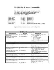
Remote Control<br />
You may control the <strong>KD</strong>-<strong>HD8x8XC</strong> switching commands by using the supplied IR Remote control.<br />
There are 8 groups of controls, one group for each Output. Each Input can be selected by<br />
pressing the Input numbers 1-8. The IR remote can also be used to change EDID settings and<br />
restore the unit to a factory default state. See the full list of IR remote control commands below.<br />
IR/Remote Control Command List<br />
No Command Description<br />
1 Power On Power On<br />
2 Power Off Power Off<br />
Video Output Setup Commands XX = [01-99], YY = [01-99]<br />
3 R1 ➔ XX Video Mode Mute Set Output XX to Video Mute ON<br />
4 R1 Video Mode All Mute Set All Output to Video Mute ON<br />
5 R1 XX Video Mode Restore Set Output XX to Video Mute OFF<br />
6 R1 Video Mode All Restore Set All Output to Video Mute OFF<br />
7 R1 XX Video Mode YY Set Output XX to Video Input YY<br />
8 R1 Video Mode YY Set All Output to Video Input YY<br />
System Control Setup Commands<br />
EDID Setup, XX = [01-08], YY = [01-08], ZZ = [01-12]<br />
9 R2 XX Bass YY Copy EDID from Output YY to Input XX<br />
10 R2 Bass YY Copy EDID from Output YY to All Inputs<br />
11 R2 XX Treble ZZ Copy EDID from Default EDID ZZ to Input XX
7<br />
Default Library EDID Control Table:<br />
01 1080i Video, 2ch PCM Audio 07 3D/1080p Video, 2ch PCM<br />
02 1080i Video, DTS/DOLBY Audio 08 3D/1080p Video, DTS/DOLBY Audio<br />
03 1080i Video, DTS/DOLBY/HD Audio 09 3D/1080p Video, DTS/DOLBY/HD<br />
Audio<br />
04 1080p Video, 2ch PCM 10 DVI 1280x1024 Video, No Audio<br />
05 1080p Video, DTS/DOLBY Audio 11 DVI 1920x1080 Video, No Audio<br />
06 1080p Video, DTS/DOLBY/HD Audio 12 DVI 1920x1200 Video, No Audio<br />
EDID Setup, XX = [01-08], YY = [01-08], ZZ = [01-12]<br />
12 R3 XX Middle YY Set Output (CEC) XX to Expansion Input YY<br />
13 R3 Middle YY Set All Output (CEC) to Expansion Input YY<br />
14 R4 R3 R2 0 0 Set Factory Default without changing EDID<br />
15 R4 R3 R2 ZZ Set Factory Default with update EDID ZZ=[01-12]<br />
(DEFAULT EDID 01-12)<br />
IR Extender:<br />
You may want to use an IR extender, such as the <strong>KD</strong>-IRKIT300. Front and Rear panel sensors are<br />
available for use with the IR extender. A wired IR serial connector is also provided at the rear of the<br />
unit.<br />
The wired IR Extender, <strong>KD</strong>-IRB3099, included in the <strong>KD</strong>-IRKIT300 uses a 3.5mm male-to-male<br />
mono cable.<br />
<strong>KD</strong>-IRB3099<br />
Wired IR Extender<br />
Back of the Unit<br />
3.5mm male-to-male<br />
mono cable<br />
<strong>KD</strong>-IRCB204<br />
Connecting Block<br />
RS-232 Commands:<br />
The <strong>KD</strong>-<strong>HD8x8XC</strong> provides access to all functions when used with an RS-232 control system.<br />
<strong>Key</strong> <strong>Digital</strong> provides a resource database for downloadable control modules at:<br />
www.keydigital.com/controlmain.aspx<br />
Connection protocol is as follows:<br />
»»<br />
Baud rate: 57,600<br />
»»<br />
Data Bits: 8<br />
»»<br />
Parity: None<br />
»»<br />
Stop Bits: 1<br />
»»<br />
Flow Control: None<br />
»»<br />
Carriage Return: Required<br />
»»<br />
Line Feed: Required<br />
RS-232 straight-through<br />
cable pin out<br />
Pin 5 – Ground<br />
Pin 3 – Receive<br />
Pin 2 – Transmit
8<br />
For a complete list of all available RS-232 commands please see the “Downloads” section on the<br />
<strong>KD</strong>-<strong>HD8x8XC</strong> product page at www.keydigital.com or use the “H” command from a terminal<br />
emulator program.<br />
NOTE: Commands are NOT case-sensitive. Spaces are shown for clarity; commands should not<br />
have any spaces. Every command below requires a carriage return at the end of the string for the<br />
command to be executed. If a new line character is received, a prompt should be sent back.<br />
Values for Commands:<br />
››<br />
H: Help - Help command. List of all RS-232 commands and Firmware version.<br />
››<br />
STA: Status Command - Displays unit status for all internal variables such as Video Input,<br />
IR Input selected for each Output, and EDID selected for each Input.<br />
››<br />
PN: Power ON - Power ON command<br />
››<br />
PF: Power Off - Power Off command<br />
<strong>KD</strong>-<strong>HD8x8XC</strong> Status Message<br />
The status response provided by the “sta” command.
9<br />
The status response provides the following information:<br />
››<br />
Firmware version<br />
››<br />
Hardware settings<br />
››<br />
Network settings<br />
››<br />
Expansion port status<br />
››<br />
Video input status (EDID, Link, HDCP, Video signal) information<br />
››<br />
Video output status (Input selection, Display, Mode, Output enabled/disabled, HPD, Link, HDCP,<br />
DDC, Video mute) information<br />
System Commands:<br />
Video Switch:<br />
»»<br />
‘SP O xx SI yy’ To switch the desired Video Input to the desired Output:<br />
»»<br />
xx = the Output number [01-08] –OR- [A] for ‘All’<br />
»»<br />
yy = the Input number [01-08] –OR- [U, D] for ‘Up’,’ Down’ respectively.<br />
‘U/D’ will increase/decrease the input number from its current position.<br />
»»<br />
This command will switch Inputs to your desired Output.<br />
»»<br />
Example: To switch Input 3 to Output 1, issue the command: ‘SPO01SI03’<br />
»»<br />
Example: To incrementally switch the Input Up from its present number for Output 1, issue<br />
the command: ‘SPO01SIU’<br />
»»<br />
Example: To switch All Outputs to Input 3, issue the command: ‘SPOASI03’<br />
IR Routing:<br />
»»<br />
‘SP C IR xx yy’ To route Serial IR signals<br />
»»<br />
xx = Output numbers [01-08] –OR- [A] for ‘All’ Outputs<br />
»»<br />
yy = Serial IR Input numbers [01-08] or [U, D] for ‘Up’,’ Down’ respectively. ‘U/D’ will<br />
increase or decrease the IR input number from its current position.<br />
»»<br />
This command will rout the selected Serial IR Input number [1-8] to the desired Output<br />
number over the CAT5e/6 connection.<br />
»»<br />
Example: ‘SPOASR02’: Will carry IR from IR Input port 2 to ‘All’ Outputs.<br />
‘SPO02SR01’: Will carry IR from IR Input port 1 to Output 2.<br />
EDID Copy and Default EDID Library:<br />
»»<br />
‘SP C EDID xx H/C/D yy’: To Copy EDID information to an Input from Output via HDMI or<br />
CAT5e/6, or from a Default Library<br />
»»<br />
xx = Input numbers [01=04] –OR- [A] for ‘All’ Inputs<br />
»»<br />
H = EDID Copy from a HDMI Output<br />
»»<br />
C = EDID Copy from a CAT5e/6 Output<br />
»»<br />
D = Default EDID Library selection (see list below)<br />
»»<br />
yy = Output numbers [01-08] when ‘H or ‘C’ variables are selected<br />
–OR-<br />
Default EDID library settings [01-08] when ‘D’ variable is selected.<br />
»»<br />
This command will either copy the EDID information from a selected Output to a specific<br />
Input (or all Inputs) or, select EDID information from an internal library of default EDID<br />
settings to a specific Input (or All Inputs).
10<br />
»»<br />
Example: To copy the EDID information from HDMI Output 2 to Input 4, issue the<br />
command: ‘SPCEDID04H02’<br />
»»<br />
Example: To copy the EDID information from CAT5e/6 Output 2 to all Inputs, issue the<br />
command: ‘SPCEDIDAC02’<br />
»»<br />
Example: To write the EDID information from the built-in default EDID library using default<br />
EDID 1 to Input 2, issue the command: ‘SPCEDID02D01’<br />
»»<br />
Default Library EDID Control Table:<br />
01 1080i Video, 2ch PCM Audio 07 3D/1080p Video, 2ch PCM<br />
02 1080i Video, DTS/DOLBY Audio 08 3D/1080p Video, DTS/DOLBY Audio<br />
03 1080i Video, DTS/DOLBY/HD Audio 09 3D/1080p Video, DTS/DOLBY/HD Audio<br />
04 1080p Video, 2ch PCM 10 DVI 1280x1024 Video, No Audio<br />
05 1080p Video, DTS/DOLBY Audio 11 DVI 1920x1080 Video, No Audio<br />
06 1080p Video, DTS/DOLBY/HD Audio 12 DVI 1920x1200 Video, No Audio<br />
Front Panel Buttons Enabled/Disabled:<br />
»»<br />
‘SP C FB E/D’<br />
»»<br />
Where ‘E’ will Enable the front panel buttons and ‘D’ will Disable the front panel buttons.<br />
»»<br />
Example: To Disable the front panel buttons, issue the command: ‘SPCFBD’<br />
Reset to Factory Defaults:<br />
»»<br />
‘SP C DF’<br />
»»<br />
restores to factory defaults without changing EDID settings.<br />
»»<br />
‘SP C DF xx’<br />
»»<br />
‘xx’ = [01-12] and is the default EDID library<br />
»»<br />
This command will return the unit to its factory default settings, including a user chosen<br />
default EDID setting. (See above for a list of possible default EDID library settings available)<br />
»»<br />
Example: To reset the unit to factory default with an EDID setting of 1080i 2CH PCM, issue<br />
the command: ‘SPCDF01’<br />
»»<br />
Example: To reset the unit to factory default with an EDID setting of 3D 1080p 2CH PCM,<br />
issue the command: ‘SPCDF07’<br />
EDID Control<br />
EDID Control HDMI Handshaking<br />
EDID (Extended Display Identification Data) is a data structure provided by a digital display to<br />
describe its capabilities to a video source. This data is also known as a “handshake” and typically<br />
includes manufacturer, serial number, product type, resolutions supported by the display, display<br />
size, pixel mapping data, etc.<br />
In a one-to-one source-display system, the EDID process is relatively simple. However, HDMI<br />
matrix systems enabled by the <strong>Digital</strong> IQ Series products are far more sophisticated as a source<br />
may be selected by multiple displays–with a variety of EDID information provided–at any given time.<br />
<strong>Key</strong> <strong>Digital</strong> EDID Control allows the integrator to choose the handshake that will be provided to<br />
each source device of the system. The EDID handshake is relayed to the source from the <strong>Digital</strong>
11<br />
IQ matrix, not from any of the displays/output devices of the system. This handshake will always<br />
be the EDID information that the source device receives.<br />
EDID Control handshaking can be provided to each source independently, or to all sources<br />
simultaneously.<br />
The EDID information is provided to a source by one of three methods:<br />
››<br />
From the internal Default Library of EDID files located within the <strong>Digital</strong> IQ software<br />
››<br />
By copying the EDID provided by any display/output device connected via the HDMI output<br />
connection<br />
››<br />
By copying the EDID provided by any display/output device connected via the CAT5e/6 output<br />
connection<br />
››<br />
Providing an EDID Handshake from the Default Library<br />
The Default Library features generic EDID handshakes that are compatible with the majority<br />
of source equipment and meet a wide-spectrum of demands in a variety of application<br />
types.<br />
››<br />
The Default Library is subject to change as new standards and desired application updates are<br />
requested.<br />
››<br />
The EDID Control library can be revised on your <strong>Digital</strong> IQ matrix via a firmware update. To verify<br />
the Default Library of your unit’s firmware, use the RS-232 Help command (“H”). See the RS-232<br />
Control Codes sections for more information.<br />
Default Library EDID Control Table:<br />
01 1080i Video, 2ch PCM Audio 07 3D/1080p Video, 2ch PCM<br />
02 1080i Video, DTS/DOLBY Audio 08 3D/1080p Video, DTS/DOLBY Audio<br />
03 1080i Video, DTS/DOLBY/HD Audio 09 3D/1080p Video, DTS/DOLBY/HD Audio<br />
04 1080p Video, 2ch PCM 10 DVI 1280x1024 Video, No Audio<br />
05 1080p Video, DTS/DOLBY Audio 11 DVI 1920x1080 Video, No Audio<br />
06 1080p Video, DTS/DOLBY/HD Audio 12 DVI 1920x1200 Video, No Audio<br />
››<br />
After executing EDID Control handshaking for your system, it is recommended to observe video<br />
and audio performance in all zones.<br />
Providing a Default Library EDID handshake to a specified source:<br />
››<br />
Via Device Manager (recommended):<br />
»»<br />
Please see the device manager manual for instructions<br />
››<br />
Via RS-232:<br />
»»<br />
“SPCEDIDxxDyy”<br />
»»<br />
xx = input Port number or “A” (all)<br />
»»<br />
yy = default library selection (01-12)<br />
»»<br />
After giving the source device a few moments to adjust its output, you may verify the<br />
handshake has been properly received and the source has complied with the handshake by<br />
using the RS-232 Input status command “STPIxx”.<br />
››<br />
Via the Remote Control:<br />
»»<br />
See the IR Remote Control section
12<br />
How to copy the EDID of any connected (HDMI or CAT5e/6) display/output device<br />
››<br />
<strong>Digital</strong> IQ products are able to poll any connected output device for its EDID information and<br />
provide that EDID to the specified source.<br />
››<br />
It is possible to poll any output device connected via the HDMI or CAT5e/6 RJ45 output<br />
connections<br />
››<br />
An exact copy of the EDID file provided by the specified output device is relayed to the specified<br />
source.<br />
››<br />
This EDID file is not stored in the <strong>Digital</strong> IQ unit’s software. Therefore, it is not possible to relay the<br />
copied EDID of an output device unless it is connected at the time of prompting the handshake.<br />
››<br />
Bear in mind that relaying an exact EDID handshake from one of the connected output devices<br />
may result in optimum performance in that respective output zone, but may also result in<br />
incompatibilities in other zones viewing that source with different display equipment.<br />
››<br />
After executing EDID Control handshaking for your system, it is recommended to observe video<br />
and audio performance in all system zones.<br />
How to provide a copy EDID of any connected display/output device<br />
››<br />
Via Device Manager (recommended):<br />
»»<br />
Please see the device manager manual for instructions<br />
››<br />
Via RS-232:<br />
»»<br />
“SPCEDIDxxH/Cyy”<br />
»»<br />
xx = input Port number or “A” (all)<br />
»»<br />
yy = Output Port number (01-08)<br />
»»<br />
H or C = output device connected via HDMI (H) or CAT6/STP (C) output connection<br />
»»<br />
After giving the source device a few moments to adjust its output, you may verify the<br />
handshake has been properly received and the source has complied with the handshake by<br />
using the RS-232 Input status command “STPIxx”.<br />
››<br />
Via the Remote Control:<br />
»»<br />
See the IR Remote Control section<br />
Control Routing via <strong>Digital</strong> IQ <br />
In addition to HDMI matrix switching, <strong>Digital</strong> IQ products are able to route IR and RS-232<br />
commands to peripheral devices. Control routing via the the <strong>KD</strong>-<strong>HD8x8XC</strong> utilizes the 3.5mm<br />
expansion ports as the control signal’s input/source and routes these control signals to desired<br />
RJ45 output(s)/destination(s). The 3.5mm stereo expansion connections and IQ Control port are<br />
engineered to carry signals in specific directions. As a result, control routing with the <strong>KD</strong>-<strong>HD8x8XC</strong><br />
is limited to one direction—from the switch to the RJ45 outputs. Control signals cannot be sent to<br />
the HDMI outputs.<br />
Utilizing <strong>Digital</strong> IQ’s Control Routing feature significantly extends the reach of your control system<br />
– adding up to 8 control ports to your control system without requiring additional master control<br />
units.<br />
There are two methods of Control Routing: Port to Port and Masking. It is possible to utilize<br />
both control routing methods within your <strong>Digital</strong> IQ matrix, but keep in mind that settings may<br />
interfere with each other and result in undesired control source - control destination connections.
13<br />
For seamless integration that fully-utilizes the <strong>Digital</strong> IQ control routing features, <strong>Key</strong> <strong>Digital</strong>’s<br />
Compass Control ® system is recommended. The Compass Control ® RS-232 and TCP-IP<br />
Manager Databases feature individual drivers for independent IR and RS-232 matrix switching.<br />
A look at the 3.5mm, RJ45, and Main ports and their respective number assignments utilized in<br />
control routing.<br />
01 02 03 04<br />
01 02<br />
03 04<br />
05 06<br />
05 06 07 08<br />
07 08<br />
Theory: Port to Port Control Routing, and Masking<br />
Port to Port Control Routing works much like a traditional matrix switch. A control signal<br />
“SPCIR0101” “SPCIR0302” “SPCIR0804”<br />
is transmitted into one 3.5mm expansion port and is routed to a specified RJ45 output. The<br />
3.5mm expansion ports are sources (inputs) for a control signal and the RJ45 ports are outputs<br />
IR<br />
CAT5e/6<br />
IR<br />
(destinations) for the control IRsignal. <strong>KD</strong>-<strong>HD8x8XC</strong> control routing <strong>KD</strong>-CATHD150Rx<br />
is unidirectional. The control<br />
signal <strong>KD</strong>-MC2500 travels from the switch (source) to the display (destination). The control sources (inputs) can<br />
CAT5e/6<br />
be connected to any 3.5mm expansion control port. A control signal is able to be sent to one or<br />
<strong>KD</strong>-CATHD150Rx<br />
many control destinations.<br />
Port to Port Control Routing in Brief:<br />
CAT5e/6<br />
››<br />
IR/RS-232 signals from a Control System to expansion ports are routed to a specified RJ45<br />
<strong>KD</strong>-CATHD150Rx<br />
destination.<br />
››<br />
Benefit: Control signals are consolidated onto the CAT cabling with video and audio signals,<br />
negating the need for additional cabling to carry control signals.<br />
››<br />
Con: Any Port to Port combination is possible, but may require many commands to establish.<br />
Output Masking Control Routing enables a highly-customizable, large-configuration IR or<br />
RS-232 distribution block. A control signal is fed into a 3.5mm expansion port and is distributed<br />
to any number of RJ45 destinations by issuing, in conjunction, the proper routing and masking<br />
<strong>KD</strong>-CATHD150Rx<br />
<strong>KD</strong>-CATHD150Rx<br />
<strong>KD</strong>-CATHD150Rx<br />
<strong>KD</strong>-CATHD150Rx<br />
commands. If commands are issued incorrectly or control connections are changed, the control<br />
signal may be disrupted.<br />
To maintain a Port to Port control routing system simultaneously with a Control Masking system,<br />
each port is able to be included or excluded in the control mask with the Mask Enable commands.<br />
“SPCIRM0F”<br />
Output Control Masking enables any combination of 3.5mm expansion ports to be routed to<br />
<strong>KD</strong>-MC2500<br />
any combination of RJ45 ports.<br />
Control Masking Routing in Brief:<br />
IR<br />
››<br />
Signals from a Control System to the main control ports are routed from specified 3.5 mm ports to<br />
any combination of RJ45 ports<br />
››<br />
Benefit: Any specified combinations of destinations are granted connection to the source control<br />
ports via a minimal amount of commands.<br />
››<br />
Con: Programming can be complex, as commands featuring Hex values may need to <strong>KD</strong>-MC2500 be issued<br />
frequently depending on how dynamic the system is.<br />
IR<br />
IR<br />
1<br />
IR<br />
IR<br />
IR<br />
RS-232<br />
IR<br />
RS-232<br />
1
14<br />
Implementing the Control Routing Features:<br />
How to Set Port to Port Control Routing (IR & RS-232)<br />
1. Determine source and destination for control signal(s):<br />
»»<br />
For Control Routing Systems: “SPCIRxxyy”<br />
»»<br />
xx = Destination (01-08 = CAT01-CAT08)<br />
»»<br />
yy = Source (01-08 = 3.5mm 01-08)<br />
2. Send IR/RS-232 command to be routed<br />
01 02 03 04<br />
05 06 07 08<br />
01 02<br />
03 04<br />
05 06<br />
07 08<br />
A Point to Point Control Routing example with IR and RS-232 Control Routing taking place<br />
“SPCIR0101” “SPCIR0302” “SPCIR0804”<br />
<strong>KD</strong>-MC2500<br />
IR<br />
IR<br />
IR<br />
CAT5e/6<br />
<strong>KD</strong>-CATHD150Rx<br />
CAT5e/6<br />
<strong>KD</strong>-CATHD150Rx<br />
CAT5e/6<br />
<strong>KD</strong>-CATHD150Rx<br />
How to Set Masking Control Routing:<br />
1. Route a 3.5mm expansion port to RJ45 output/destination ports:<br />
»»<br />
a. To route a 3.5mm expansion port to all RJ45 output/destination ports:<br />
<strong>KD</strong>-CATHD150Rx<br />
»»<br />
IR/RS-232: SPCIRAyy<br />
IR<br />
<strong>KD</strong>-CATHD150Rx<br />
IR<br />
»»<br />
xx = Destination (01-08 = CAT01-CAT08)<br />
“SPCIRM0F”<br />
»»<br />
yy = Control signal source (01-08=3.5mm expansion port 01-08)<br />
2<br />
IR<br />
RS-232<br />
3<br />
<strong>KD</strong>-CATHD150Rx<br />
IR<br />
IR<br />
2<br />
IR<br />
RS-232<br />
<strong>KD</strong>-CATHD150Rx<br />
»»<br />
Note: this command may interrupt existing Port to Port routes in place<br />
»»<br />
b. To avoid interruption of existing Port to Port routes, route individually:<br />
»»<br />
IR/RS-232: SPCIRxxyy<br />
2. Choose the RJ45 ports to which mask applies:<br />
»»<br />
IR/RS-232 Mask Enable command:<br />
»»<br />
SPCIRMh1h2<br />
»»<br />
c. Hex values for the above commands:<br />
»»<br />
h1 is a hex value for RJ45 control destinations on RJ45 8-5<br />
»»<br />
h2 is a hex value for RJ45 control destinations on RJ45 4-1<br />
3. Establish Output Mask:<br />
1<br />
»»<br />
a. Hex <strong>Key</strong>: 0 = Connection Disabled 1 = Connection Enabled<br />
3<br />
IR<br />
<strong>KD</strong>-MC2500<br />
<strong>KD</strong>-MC2500<br />
1
15<br />
01 02 03 04<br />
Hex Binary Hex Binary Hex Binary Hex Bin<br />
0 0000 4 0100 8 1000 C 1100<br />
1 0001 505 0101 06 07 9 1001 08<br />
D 1101<br />
2 0010 6 0110 A 1010 E 1110<br />
3 0011 7 0111 B 1011 F 1111<br />
“SPCIR0101” “SPCIR0302” “SPCIR0804”<br />
»»<br />
b. Hex values for the IRbelow Output Masking commands:<br />
IR<br />
»»<br />
h1 is a hex value IRfor RJ45 control destinations on RJ45 <strong>KD</strong>-CATHD150Rx 8-5<br />
<strong>KD</strong>-MC2500<br />
»»<br />
h2 is a hex value for RJ45 control destinations on RJ45 4-1<br />
CAT5e/6<br />
»»<br />
c. IR/RS-232 Output Masking Command:<br />
<strong>KD</strong>-CATHD150Rx<br />
»»<br />
i. SPCIRMh1h2h<br />
4. Send IR/RS-232 command to be distributed from main control CAT5e/6 ports (output masking),<br />
or routed to main control ports (input masking)<br />
<strong>KD</strong>-CATHD150Rx<br />
5. (Optional) Disconnect all destinations:<br />
»»<br />
a. IR/RS-232 Output Masking: SPCIRM00<br />
A Main to Port Control Routing example in which a command is distributed to RJ45 outputs<br />
CAT5e/6<br />
01 02<br />
03 04<br />
05 06<br />
07 08<br />
<strong>KD</strong>-CATHD150Rx<br />
IR<br />
<strong>KD</strong>-CATHD150Rx<br />
IR<br />
<strong>KD</strong>-CATHD150Rx<br />
IR<br />
<strong>KD</strong>-CATHD150Rx<br />
IR<br />
“SPCIRM0F”<br />
<strong>KD</strong>-MC2500<br />
IR<br />
<strong>KD</strong>-MC2500<br />
1<br />
IR<br />
RS-232<br />
RS-232<br />
IR<br />
1<br />
2<br />
3<br />
2<br />
3<br />
No Connection
16<br />
“SPCIR0101” “SPCIR0302” “SPCIR0804”<br />
IR<br />
IR<br />
IR<br />
<strong>KD</strong>-CATHD150Rx<br />
<strong>Digital</strong> <strong>KD</strong>-MC2500 IQ Control Routing with Compass Control ® System<br />
<strong>Key</strong> <strong>Digital</strong>’s Compass Control ® System features drivers to maximize the capability and ease<br />
<strong>KD</strong>-CATHD150Rx<br />
of use for control routing with <strong>Digital</strong> IQ products. Each control routing matrix (IR, RS-232 and<br />
IP) features an independent driver in the <strong>Key</strong> <strong>Digital</strong> (IR, RS-232 and CAT5e/6 IP) Manager database,<br />
essentially treating each independent routing matrix as its own independent device. The drivers<br />
<strong>KD</strong>-CATHD150Rx<br />
are named <strong>KD</strong>-<strong>HD8x8XC</strong>_IR and <strong>KD</strong>-<strong>HD8x8XC</strong>_RS.<br />
Integrating <strong>Digital</strong> IQ with Compass Control utilizes a method of Control Routing that is a hybrid<br />
of the Port to Port and masking methods because it takes advantage of the <strong>KD</strong>-MC2500’s<br />
(Compass Control Master Controller) flexible port configuring, which does not limit each port’s<br />
protocol to the protocol of the assigned device. Instead, the protocol of each <strong>KD</strong>-MC2500 port<br />
is determined by the device that the control signal is intended for, allowing multiple devices to be<br />
assigned to any port. For example, a single port can issue an RS-232 command at 9600 bits per<br />
<strong>KD</strong>-CATHD150Rx<br />
<strong>KD</strong>-CATHD150Rx<br />
<strong>KD</strong>-CATHD150Rx<br />
<strong>KD</strong>-CATHD150Rx<br />
second, and then issue the next command at 57,600. It is important to ensure that proper delays<br />
have been added to the sequence.<br />
The flexibility of the <strong>KD</strong>-MC2500 ports enables a minimal amount of connections from the master<br />
controller to the <strong>Digital</strong> IQ. Providing three ports from the master controller to the <strong>Digital</strong> IQ is<br />
“SPCIRM0F”<br />
recommended, and will provide connections to control the <strong>Digital</strong> IQ’s independent matrix layers<br />
(Video, Audio, IR, IP, RS-232), external IR devices (via control routing), and external RS-232<br />
<strong>KD</strong>-MC2500<br />
devices (via control routing).<br />
IR<br />
Recommended connectivity between <strong>Digital</strong> IQ and <strong>KD</strong>-MC2500:<br />
1) DB-9 to DB-9 Straight cable, providing control over the <strong>Digital</strong> IQ<br />
2) 3.5mm Mono which will be the IR source for control routing to external IR devices<br />
3) 3.5mm Stereo which will be the RS-232 source for control routing to external RS-232 devices<br />
IR<br />
IR<br />
1<br />
IR<br />
CAT5e/6<br />
CAT5e/6<br />
IR<br />
<strong>KD</strong>-MC2500<br />
IR<br />
RS-232<br />
RS-232<br />
IR<br />
1<br />
2<br />
3<br />
2<br />
3<br />
Adding the <strong>KD</strong>-<strong>HD8x8XC</strong>_IR and <strong>KD</strong>-<strong>HD8x8XC</strong>_RS to No your Connection Compass Navigator System<br />
Configuration Device Library will add two device icons:<br />
»»<br />
Adding <strong>KD</strong>-<strong>HD8x8XC</strong>_IR inserts “<strong>KD</strong>-<strong>HD8x8XC</strong>_IR ” and “<strong>KD</strong>-<strong>HD8x8XC</strong>_IR ”.<br />
»»<br />
“<strong>KD</strong>-<strong>HD8x8XC</strong>_IR ” carries the RS-232 command determining IR destination<br />
and IR source matrix switching and is depicted with connection number 1 in the<br />
above diagram. In the Compass Navigator Controlling ARC Input Flow of Display Connectivity Tree, the<br />
“<strong>KD</strong>-<strong>HD8x8XC</strong>_IR ” device should be connected to the Main RS-232 port<br />
Male-to-Male 3.5mm cable<br />
of the <strong>KD</strong>-MC2500.<br />
To ARC Output of AV Receiver<br />
PCM <strong>Digital</strong> Audio<br />
Carried on One RCA
17<br />
»»<br />
“<strong>KD</strong>-<strong>HD8x8XC</strong>_IR ” is the connection that carries the IR signals intended to<br />
be routed to IR destinations. In the Compass Navigator Control Connectivity Tree, the<br />
“<strong>KD</strong>-<strong>HD8x8XC</strong>_IR ” device can be connected to the or any of the eight 3.5mm<br />
multifunction ports of the <strong>KD</strong>-MC2500 (as long as the ports are pre-configured to IR)<br />
and doing so will create a tree expansion for 8 IR destinations<br />
Brand: <strong>Key</strong> <strong>Digital</strong> → Device Type: IR Router → <strong>KD</strong>-<strong>HD8x8XC</strong>_IR<br />
Adding “<strong>KD</strong>-<strong>HD8x8XC</strong>_IR ” to the Main IR Port<br />
(“IRout-60”) provides 8 additional IR connectivity points.<br />
Ports 5 and 6 (RJ45 ports on Outputs 5 and 6, respectively)<br />
are routing control to the “Lab” and “Lobby” displays.
18<br />
»»<br />
Adding <strong>KD</strong>-<strong>HD8x8XC</strong>_RS inserts “<strong>KD</strong>-<strong>HD8x8XC</strong>_RS ” and “<strong>KD</strong>-<strong>HD8x8XC</strong>_RS ”.<br />
»»<br />
“<strong>KD</strong>-<strong>HD8x8XC</strong>_RS ” carries the RS-232 command determining RS-232<br />
destination and RS-232 source matrix switching and is depicted with connection<br />
number 1 in the above diagram. In the Compass Navigator Controlling Flow<br />
Connectivity Tree, the “<strong>KD</strong>-<strong>HD8x8XC</strong>_RS ” device should be connected to the<br />
Main RS-232 port of the <strong>KD</strong>-MC2500.<br />
»»<br />
“<strong>KD</strong>-<strong>HD8x8XC</strong>_RS ” is the connection that carries the RS-232 signals intended<br />
to be routed to RS-232 destinations. In the Compass Navigator Control Connectivity<br />
Tree, the “<strong>KD</strong>-<strong>HD8x8XC</strong>_RS ” device can be connected to the any of the eight<br />
3.5mm multifunction ports of the <strong>KD</strong>-MC2500 (as long as the ports are pre-configured<br />
to RS-232) and doing so will create a tree expansion for 8 RS-232 destinations.<br />
Brand: <strong>Key</strong> <strong>Digital</strong> → Device Type: RS232 Router → <strong>KD</strong>-<strong>HD8x8XC</strong>_RS
Adding “<strong>KD</strong>-<strong>HD8x8XC</strong>_RS ” to the Main IR Port (“RS-1”) provides 8 additional RS-232<br />
connectivity points. <strong>KD</strong>-MC2500 ports 5, 6, 7, and 8 (RJ45 ports on Outputs 1, 2, 3, and 4,<br />
respectively) are routing control to the “Board Room” and “Conference Room”, “Cafeteria”, and<br />
“Training” displays.<br />
19
20<br />
IR<br />
Audio Return Channel<br />
Audio Return Channel features rely on CEC to work effectively. CEC 1 is not enabled through the<br />
<strong>KD</strong>-<strong>HD8x8XC</strong> matrix; therefore a CEC connection must be made elsewhere. This connection can<br />
be enabled by connecting two HiFi Pro HDMI cables together with a male to male 3.5mm stereo<br />
cable from an ARC supported TV and an ARC supported AV Receiver. The audio return channel<br />
is not output via HDMI, but instead it is sent to the corresponding 3.5mm expansion port of the<br />
output to which the ARC audio is connected to. A common 3.5mm stereo to L/R 2 RCA 3 Y-cable<br />
2 3<br />
may be used to connect to your AVR, however, the audio output signal will be PCM digital and will<br />
only be carried on one of the RCA leads.<br />
Example: An ARC compatible display is connected to output 8. The audio will be sent to 3.5mm<br />
expansion port number 8.<br />
IR<br />
RS-232<br />
No Connection<br />
IR<br />
RS-232<br />
<strong>KD</strong>-MC2500<br />
1<br />
ARC Input of Display<br />
Male-to-Male 3.5mm cable<br />
To ARC Output of AV Receiver<br />
PCM <strong>Digital</strong> Audio<br />
Carried on One RCA<br />
ARC Requirements:<br />
»»<br />
Display that supports ARC<br />
»»<br />
AV Receiver that supports ARC<br />
»»<br />
Champion Series HiFi Commercial PRO HDMI Cables<br />
»»<br />
Male to Male Stereo Cable<br />
»»<br />
3.5mm to RCA cable
21<br />
Specifications<br />
Technical:<br />
»»<br />
Input (Each): 8 HDMI; 8 wired IR on 3.5 mm stereo jack connector per slot<br />
»»<br />
Output (Each): 8 HDMI; 8 dual- CAT5e/6 on RJ45 connectors;<br />
»»<br />
Bandwidth: TMDS bandwidth 3.4 Gb/s<br />
»»<br />
Control: IR sensor front/rear; IR remote control, RS-232 Tx/Rx lines<br />
»»<br />
Video/Audio Matrix Switching: Full matrix switching for HDMI Video matrix<br />
»»<br />
Deep Color Support: Supports 12 Bit Deep Color<br />
»»<br />
HDMI ® and HDCP Licensing: Fully licensed and compatible with all HDMI<br />
and HDCP technologies<br />
»»<br />
EDID Control:An internal EDID library featuring 12 handshakes. The ability to copy EDID<br />
information from a connected display to any number of inputs.<br />
»»<br />
DDC Signal (Data):Input DDC Signal: 5 Volts p-p (TTL)<br />
»»<br />
HDMI Video/Audio Signal:Input Video Signal: 1.2 Volts p-p<br />
»»<br />
DDC Communication:EDID and HDCP Bi-directional Transparency from Display to Source<br />
»»<br />
Wired IR: modulated IR signal input, 0-5V TTL or -10to +10V.<br />
»»<br />
Power: External Power Supply. 6V/7.5A<br />
General:<br />
»»<br />
Regulation: CE, RoHS, WEEE<br />
»»<br />
Rack Mount: 2U, Full Rack Width (rack ears included)<br />
»»<br />
Enclosure: Black Metal<br />
»»<br />
<strong>KD</strong>-<strong>HD8x8XC</strong> Product Dimensions: 17.3” W x 6.6” D x 3.46” H<br />
»»<br />
<strong>KD</strong>-<strong>HD8x8XC</strong> Product Weight: 6 lb.<br />
»»<br />
Shipping Weight: 9 lb
22<br />
Important Product Warnings:<br />
1. Connect all cables before providing power to the unit.<br />
2. Test for proper operation before securing unit behind walls or in hard to access spaces.<br />
3. If installing the unit into wall or mounting bracket into sheet-rock, provide proper screw support<br />
with bolts or sheet-rock anchors.<br />
Safety Instructions:<br />
Please be sure to follow these instructions for safe operation of your unit.<br />
1. Read and follow all instructions.<br />
2. Heed all warnings.<br />
3. Do not use this device near water.<br />
4. Clean only with dry cloth.<br />
5. Install in accordance with the manufacturer’s instructions.<br />
6. Do not install near any heat sources such as radiators, heat registers, stoves, or other<br />
apparatus (including amplifiers) that produce heat.<br />
7. Only use attachments/accessories specified by the manufacturer.<br />
8. Refer all servicing to qualified service personnel. Servicing is required when the device has<br />
been damaged in any way including:<br />
»»<br />
Damage to the power supply or power plug<br />
»»<br />
Exposure to rain or moisture<br />
Power Supply Use:<br />
You MUST use the Power Supply provided with your unit or you VOID the<br />
<strong>Key</strong> <strong>Digital</strong> ® Warranty and risk damage to your unit and associated equipment.
23<br />
How to Contact <strong>Key</strong> <strong>Digital</strong> ®<br />
System Design Group (SDG)<br />
For system design questions please contact us at:<br />
››<br />
Phone: 914-667-9700<br />
››<br />
E-mail: sdg@keydigital.com<br />
<strong>Key</strong> <strong>Digital</strong> Trainings<br />
For questions about <strong>Key</strong> <strong>Digital</strong> ® Trainings please contact us at:<br />
››<br />
Phone: 914-667-9700<br />
››<br />
E-mail: training@keydigital.com<br />
Customer Support<br />
For customer support questions please contact us at:<br />
››<br />
Phone: 914-667-9700<br />
››<br />
E-mail: customersupport@keydigital.com<br />
Technical Support<br />
For technical questions about using <strong>Key</strong> <strong>Digital</strong> ® products, please contact us at:<br />
››<br />
Phone: 914-667-9700<br />
››<br />
E-mail: tech@keydigital.com<br />
Marketing and Public Relations:<br />
For marketing and public relations information, please contact us at:<br />
››<br />
Phone: 914-667-9700<br />
››<br />
E-mail: marketing@keydigital.com<br />
Repairs and Warranty Service<br />
Should your product require warranty service or repair, please obtain a <strong>Key</strong> <strong>Digital</strong> ® Return Material<br />
Authorization (RMA) number by contacting us at:<br />
››<br />
Phone: 914-667-9700<br />
››<br />
E-mail: rma@keydigital.com<br />
Feedback<br />
Please email any comments/questions about the manual to:<br />
››<br />
E-mail: customersupport@keydigital.com
24<br />
Warranty Information<br />
All <strong>Key</strong> <strong>Digital</strong> ® products are built to high manufacturing standards and should provide years of<br />
trouble-free operation. They are backed by a limited two-year parts and labor warranty.
Rev 0 – 11.15.2012<br />
<strong>Key</strong> <strong>Digital</strong> ® , led by digital video pioneer Mike Tsinberg,<br />
develops and manufactures high quality, cutting-edge<br />
technology solutions for virtually all applications where<br />
high quality video imaging is important. <strong>Key</strong> <strong>Digital</strong> ®<br />
is at the forefront of the video industry for Home Theater<br />
Retailers, Custom Installers, System Integrators,<br />
Broadcasters, Manufacturers, and Consumers.<br />
<strong>Key</strong> <strong>Digital</strong> ® Systems :: 521 East 3rd Street :: Mount Vernon, NY 10553<br />
Phone : 914.667.9700 Fax : 914.668.8666 Web : www.keydigital.com