Chapter 22 Materials Selection and Design Considerations
Chapter 22 Materials Selection and Design Considerations
Chapter 22 Materials Selection and Design Considerations

Create successful ePaper yourself
Turn your PDF publications into a flip-book with our unique Google optimized e-Paper software.
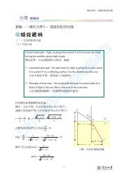
Figure <strong>22</strong>.29<br />
Photograph of a<br />
leadframe on which<br />
the central plate <strong>and</strong><br />
contact leads are<br />
labeled. 2�.<br />
(Leadframe supplied<br />
by National<br />
Semiconductor<br />
Corporation.<br />
Photograph by<br />
Dennis Haynes.)<br />
<strong>22</strong>.17 Die Bonding • W121<br />
<strong>and</strong> die-bonding adhesive must also be thermally conductive to facilitate the dissipation<br />
of heat generated by the IC. (3) A coefficient of thermal expansion comparable<br />
to that of Si is highly desirable; a thermal expansion mismatch could destroy<br />
the integrity of the bond between the IC <strong>and</strong> the central plate as a result of thermal<br />
cycling during normal operation. (4) The leadframe material <strong>and</strong> substrate must<br />
also adhere to the die-bonding adhesive, <strong>and</strong> the adhesive <strong>and</strong> substrate must also<br />
be electrically conductive. (5) A secure <strong>and</strong> electrically conductive joint between<br />
the leadframe <strong>and</strong> the connecting wires must be possible. (6) The leadframe must<br />
be resistant to oxidation <strong>and</strong> retain its mechanical strength during any thermal cycling<br />
that may accompany the die-bonding <strong>and</strong> encapsulation procedures. (7) The<br />
leadframe must also withst<strong>and</strong> corrosive environments at high temperatures <strong>and</strong><br />
high humidities. (8) It must be possible to mass produce the leadframes economically.<br />
Normally, they are stamped from thin metal sheets.<br />
Several alloys have been used for the leadframe with varying degrees of success.<br />
The most commonly used materials are copper-based alloys; the compositions,<br />
electrical <strong>and</strong> thermal conductivities, <strong>and</strong> coefficients of thermal expansion for two<br />
of the most popular ones (C19400 <strong>and</strong> C19500) are listed in Table <strong>22</strong>.6. For the most<br />
part, they satisfy the criteria listed in the preceding paragraph. Also listed in the<br />
table are the compositions of two other alloys (Kovar <strong>and</strong> Alloy 42) that have been<br />
used extensively in leadframes.The desirability of these latter two alloys lies in their<br />
relatively low coefficients of thermal expansion, which are closely matched to that<br />
of Si [i.e., 2.5 � 10 ]. However, from Table <strong>22</strong>.6 it may also be noted that<br />
�6 (�C) �1<br />
both electrical <strong>and</strong> thermal conductivities for Kovar <strong>and</strong> Alloy 42 are inferior to<br />
the conductivity values for the C19400 <strong>and</strong> C19500 alloys.<br />
<strong>22</strong>.17 DIE BONDING<br />
The die-bonding operation consists of attaching the IC chip to the central supporting<br />
leadframe plate. For the copper alloys noted in Table <strong>22</strong>.6, attachment may be made<br />
using a gold–silicon eutectic solder; however, melting of the solder requires heating<br />
the assembly to 500�C (900�F).<br />
Another adhesive possibility is an epoxy bonding agent, which is normally<br />
filled with metal particles (frequently Ag) so as to provide both a thermally <strong>and</strong>